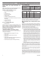
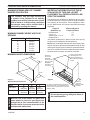
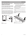
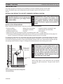
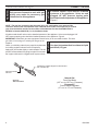
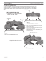
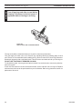
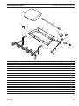
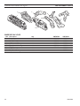
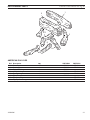
1
Vented Outdoor Gas
Log Set
Installation And Operating
Instructions
Models:
VWFOD24, VWFOD30
Natural Gas or Propane/LPG
Control Type: Manual Match Light
WARNING
For Outdoor Use ONLY
WARNINGS
If the information in this manual is not followed
exactly, a fire or explosion may result causing
property damage, personal injury or loss of
life.
– Do not store or use gasoline or other
flammable vapors and liquids in the vicinity
of this or any other appliance.
– WHAT TO DO IF YOU SMELL GAS
• Do not try to light any appliance.
• Do not touch any electrical switch; do not
use any phone in your building.
• Immediately call your gas supplier from
a neighbor's phone. Follow the gas
supplier's instructions.
• If you cannot reach your gas supplier,
call the fire department.
– Installation and service must be performed
by a qualified installer, service agency or
the gas supplier.
This gas log set is to be installed only in a
solid-fuel burning fireplace with a working flue
constructed of noncombustible material.
WARNING: Improper installation, adjustment,
alteration,
0546 service or maintenance can cause
injury
or property
VWFOD
cover damage. Read the installation, operating and maintenance instructions
thoroughly before installing or servicing this
equipment.
Approved for outdoor use
Approved to:
CSA-4.96
CSA-CR97-003 (NG Only)
INSTALLER: Leave this manual with the appliance.
CONSUMER: Retain this manual for future reference.
20300546 1/10 Rev. 1
CONTENTS
VWFOD Vented Outdoor Gas Log Set
Thank you and congratulations on your purchase of an
MHSC Gas Log Set
PLEASE READ THE INSTALLATION AND OPERATION INSTRUCTIONS BEFORE USING THE APPLIANCE!
IMPORTANT: Read all instructions and warnings carefully before starting installation.
Failure to follow these instructions may result in a possible fire hazard and will void the warranty.
Product Features & Specifications ........................... 4
Fireplace & Hearth Dimensions................................. 5
Installation in a Fireplace with Restrictive Barrier.... 5
Installation.................................................................... 6
WARNING
Important Safety Information .................................... 3
Never connect unit to private (non-utility)
gas wells. This gas is commonly known
as wellhead gas.
Damper Stop Installation......................................... 6
Check Gas Type...................................................... 7
Install Gas Line........................................................ 8
Log Placement ............................................................ 9
VWF24 Massive Oak Log ...................................... 9
VWF30 Massive Oak Log .....................................11
VWF24 American Oak Log . ................................. 12
VWF30 American Oak Log . ................................. 13
VWF30/24 Split River Oak Log ............................ 15
VWF36/30 Split River Oak Log ............................ 17
VWF24 Split Pine ................................................. 18
VWF30 Split Pine ................................................. 20
VWF30/24WP Weathered Pine Log ..................... 22
WF36/30WP Weathered Pine Log........................ 24
VWFOD
Certified To
CSA-4.96
CSA - CR97-003 (NG Only)
Operating Instructions.............................................. 25
Manual Match Control Lighting ............................ 25
Flame Appearance................................................ 26
Fireplace Draft Test................................................... 27
WARNING
Replacement Parts Lists . ........................................ 29
Assembly............................................................... 29
Massive Oak Logs................................................. 30
American Oak Logs............................................... 31
Split River Oak Logs.............................................. 32
Split Pine Logs...................................................... 33
Weathered Pine Logs............................................ 34
This appliance is for installation only in
a solid fuel burning fireplace (masonry
fireplace or manufactured fireplace).
WARNING
Cleaning and Servicing . .......................................... 28
FOR MASSACHUSETTS RESIDENTS ONLY:
Massachussetts Residents Only............................. 35
Warranty..................................................................... 36
This product must be installed by a licensed
plumber of gas fitter when installed within
the Commonwealth of Massachusetts.
20300546
IMPORTANT SAFETY INFORMATION
VWFOD Vented Outdoor Gas Log Set
OWNER
INSTALLER
Please leave these instructions with the appliance.
Please retain these instructions for future reference.
IMPORTANT
WARNING
Read these instructions carefully before installing or trying to operate this vent-free gas heater.
• Any change to this heater or its controls can be dangerous.
• Improper installation or use of the heater can cause serious injury or
death from fire, burns, explosion or carbon monoxide poisoning.
• Do not allow fans to blow directly into the fireplace. Avoid any drafts
that alter burner flame patterns.
• Do not use a blower insert, heat exchanger insert or other accessory,
not approved for use with this heater where applicable.
1. The installation, combustion and ventilation air must
conform with local codes or, in the absence of local
codes, with the National Fuel Gas Code, ANSI Z223.1,
or the CSA-B149 Installation code (series). This unit
complies with CSA-4.96 US and CR97-003, Outdoor
Fireplaces for installation in solid-fuel burning fireplace.
2. Installation and repair should be done by a qualified
service person. MHSC Vented Gas Logs must be
installed only in a masonry or a UL-127 solid-fuel
fireplace with minimum venting requirements, see
installation section.
3. To prevent malfunction, gas log set and flue should
be cleaned at least annually by a professional service
person. More frequent cleaning may be required due
to excessive lint from carpeting, etc. It is imperative
that control compartments, burners and circulating air
passageways be kept clean.
4. A damper clamp must be installed to provide the
minimum permanent vent opening to vent flue
products, Refer to installation instructions.
5. Never burn solid fuels in a fireplace where a gas log
set is installed.
6. This appliance must not be used with glass doors
in the closed position. A fireplace screen must be
in place when the log set is burning. Provisions for
adequate combustion air must be provided. Adequate
combustion air usually results in all flames curling into
the fireplace away from the screen and up the flue.
8. Keep room area clear and free from combustible
materials, gasoline and other flammable vapors and
liquids.
9. Children and adults should be alerted to the hazard
of high surface temperature and should stay away to
avoid burns or clothing ignition.
10. Young children should be carefully supervised when
they are in the same room with the gas log set in operation.
20300546
11. Do not place clothing or other flammable material near
the fireplace when the gas logs are in use.
12. Do not use this gas log set if any part has been underwater. Immediately call a qualified service technician
to inspect the gas logs and replace any part of the
control system and any gas control which has been
under water.
13. The gas log set must be isolated from the gas supply
piping system by closing its individual manual shutoff
valve during any pressure testing of the gas supply
piping system at test pressures equal to or less than
1/2 psig (3.5kPa).
14. Secure gas log set to fireplace.
15. This log set will burn off the paint on the front grate
bar. Note: See cleaning section for refurbishing.
16. Inspect the burner before each use of the appliance.
The burner must be replaced prior to operation if there
is evidence the burner is damaged. Use only burner
specified by manufacturer.
LP-cylinder enclosures, if provided by the consumer must
conform to the design parameters as detailed on Page 4.
Installation of this vented gas log in the Commonwealth of Massachusetts requires the damper be
permanently removed or welded in the full open
position. In addition, a naturally vented gas log may
not be installed in a bedroom or bathroom in the Commonwealth of Massachusetts. Flex line installation
must not exceed 36".
VWFOD Vented Outdoor Gas Log Set
GETTING STARTED - Features and SPECIFICATIONS
Make sure you have received all
parts:
Check your packing list to verify that all listed parts have
been received. You should have the following:
BURNER - GRATE ASSEMBLY 24" & 30"
• Burner and Valve Assembly
• Grate
• Lava Rocks (x 4)
• Extenders with Knob
• Damper Clamp
• Installation /Operating Instructions
• 3/8" Aluminum tube with 3/8" 90° elbow, 1/2" to 3/8"
tube fitting
4, Mounting Screws
•
• Regulator (LP Only)
24" or 30" Refractory logs
• Individual Logs
Carefully inspect the contents for shipping damage. If any
parts are missing or damaged, immediately inform the
dealer from whom you purchased the appliance. Do not
attempt to install any part of the appliance unless you
have all parts in good condition.
ITEMS REQUIRED FOR INSTALLATION
Ensure that the following items are available before proceeding with installation:
• External regulator (for propane/L.P.G. only)
• Shutoff valve
• Piping which complies with local codes
• Pipe wrench
• Pipe sealant approved for use with propane/L.P.G.
(Resistant to sulfur compounds)
• Drill with masonry bit (for mounting to the floor)
GAS pressures
Inlet Minimum
Inlet Maximum
Natural Propane (LP)
4.0” w.c.
10.0” w.c.
10.0” w.c.
13.0” w.c.
Gas Specifications
Model
Fuel
Control
VWF24N
Nat.
Manual
VWF24P
LP
Manual
VWF30N
Nat.
Manual
VWF30P
LP
Manual
Nominal
Btu/hr
90,000
60,000
90,000
60,000
NOTE: Actual performance, flame height, Btu/hr will vary
with specific installation, gas pressure, shutoff valve position
(fully open), valve type, and firebox draft conditions.
ENCLOSURES FOR LP-GAS SUPPLY SYSTEMS
Enclosures for LP-gas supply cylinders shall be ventilated by
openings at the level of the cylinder valve and at floor level. The
effectiveness of the opening(s) for purposes of ventilation shall
be determined with the LP-gas supply cylinder(s) in place. This
shall be accomplished by one of the following:
a. One side of the enclosure shall be completely open; or
b. For an enclosure having four sides, a top and a bottom:
1. At least two ventilation openings at cylinder valve level shall
be provided in the side wall, equally sized, spaced at 180
degrees (3.14rad), and unobstructed. Each opening shall
have a total free area of not less than 1/2 square inch per
pound (3.2 sq. cm/kg) of stored fuel capacity and not less
than a total free area of 10 square inches (64.5 sq. cm).
2. Ventilation opening(s) shall be provided at floor level and
shall have a total free area of not less than 1/2 square inch
per pound (3.2 sq. cm/kg) of stored fuel capacity and not
less than a total free area of 10 square inches (64.5 sq. cm).
If ventilation openings at floor level are in a side all, there
shall be at least two openings. The bottom of the openings
shall be at floor level and the upper edge no more than 5
inches (127 mm) above the floor. The openings shall be
equally sized, spaced at 180 degrees (3.14 rad) and unobstructed.
3. Every opening shall have minimum dimensions so as to
permit the entrance of a 1/8 inch (3.2 mm) diameter rod.
Cylinder valves shall be readily accessible for hand operation.
A door on the enclosure to gain access to the cylinder valves is
acceptable, provided it is non-locking and can be opened without
the use of tools.
There shall be a minimum clearance of 2 inches (51 mm) between
the lower surface of the floor of the LP-gas supply cylinder enclosure and the ground.
The design of the appliance shall be such that (1) the LP-gas
supply cylinder(s) can be connected, disconnected and the connections inspected and tested outside the cylinder enclosure; and
(2) those connections which could be disturbed when installing
the cylinder(s) in the enclosure can be leak tested inside the
enclosure.
20300546
FIREPLACE and HEARTH DIMENSIONS
VWFOD Vented Outdoor Gas Log Set
WARNING
Minimum Opening Area of Chimney
Damper for Venting
IMPORTANT INFORMATION FOR THE INSTALLATION OF THIS GAS LOG SET
PLACEMENT IN A FIREPLACE WITH A RESTRICTIVE BARRIER
The fireplace and gas logs function as
a system. If the fireplace is not drafting
properly and spilling into the room (check
with a match or a smoke stick), reposition
the damper clamp until a positive draft is
obtained by opening the damper.
The following are guidelines for placing a gas log set in
a fireplace that has a restrictive barrier along the bottom
front opening of the fireplace. Some examples of barriers are glass/screen door frames and sunken/recessed
fireplaces.
Height of
Minimum Depth of
Restriction (x)
Fireplace/Firebox
No Restriction
13”
1/2” to 1Z\x”
15”
Greater than 1Z\x” to 3”
15”
Greater than 3”
*
*Any barrier greater than 3” placed in front of the gas log
set is not recommended by the manufacturer.
MINIMUM CHIMNEY HEIGHT and flue
opening
Chimney Height
6'
8'
10'
15'
20'
30'
Flue Opening
64 sq in
64 sq in
64 sq in
51 sq in
51 sq in
51 sq in
NOTE: Non combustible material such as refractory brick
may be used to line the floor of the fireplace in order to raise
the height of the gas log set in relation to a restrictive barrier.
If the unit is raised, the minimum height dimension listed in
the homeowner’s manual must not be exceeded.
MINIMUM HEARTH DIMENSIONS
A
FP2641
B
Figure 1 Minimum Hearth Dimensions
WARNING
Model
VWFOD24
VWF0D30
A
B
C
27"
13Z\x"
30"
FP2641
(686 mm) (343 mm) (762 mm)
min hearth dims
33"
13Z\x"
36"
(838 mm) (343 mm) (314 mm)
Barriers such as the bottom of a glass door
frame placed in front of a gas log set can
change the air flow characteristics of the
fireplace which in turn can cause the unit to
overheat and malfunction.
20300546
X
Figure 2
X = Height of restrictive barrier caused by
glass door frames, recessed fireplaces, etc.
from the base or bottom surface of the unit.
(Refer to Table).
CAUTION
C
The log set should be
placed against or as
near as possible to the
rear wall of the fireplace/
firebox.
Glass door
frames with
adjustable
louvers should
have the lovers
fully open
while the unit is
in operation
Depth of
fireplace/
firebox. (Refer
toTable).
FP2642
Do not operatefireplace
gas log w
with
glass doors in
barrier
the closed position.
INSTALLATION
VWFOD Vented Outdoor Gas Log Set
Install and operate the appliance
as directed in this manual.
Damper stop installation
A damper stop must be provided with the unit. The damper
stop must be installed as shown in Figure 3 to prevent
full closure of the fireplace damper blade and provide a
minimum flue opening, per table on page 5.
Should the clamp not fit, or provide the required permanent
opening from the table, have the damper cut to provide
a minimum permanent opening or install a permanent
stop.
FOR MASSACHUSETTS RESIDENTS ONLY
Installation of this vented gas log set in the Commonwealth
of Massachusetts requires the damper be permanently
removed or welded in the fully open position. In addition, a
naturally vented gas log may not be installed in a bedroom
or bathroom in the Commonwealth of Massachusetts.
Before installing the appliance:
• Turn off gas supply to fireplace or firebox.
• Clean the fireplace floor and chimney before installing the log set. Seal any ash clean-out doors to
protect the unit from down drafts.
Assembly procedure
1. Place grate/burner assembly into firebox with the
front pan facing forward.
2. Drill two (2) 5/32" diameter holes approximately 1Z\x"
deep.
3. Anchor the front pan to the floor using the screws provided.
Proper installation of the grate is essential to prevent
any movement of the gas logs and controls during
operation.
Damper Stop
Damper
FP2370
Screws
Figure 3 Damper Stop Installation
FP2370
FP2643
Figure 4 Secure Grate/Burner Assembly into Firebox
damper
FP2643
secure grate
20300546
CONNECT THE GAS
VWFOD Vented Outdoor Gas Log Set
check gas type
Use proper gas type for the log set you are installing. If you have conflicting gas type, do not install
log set. See dealer where you purchased the log set for proper log set for your gas type or conversion kit.
A qualified installer or service person must
connect appliance to gas supply. Follow
all local codes.
CAUTION
WARNING
Install gas piping to log set / burner system location
For propane/LP units, never connect burner
directly to the propane/LP supply. This
burner system requires an external regulator
(not supplied). Install the external regulator
between the burner system and propane/LP
supply.
installation items needed
Before installing the burner system, make sure you have the items listed below.
• External regulator • Piping (check local codes)
• Sealant (resistant to propane/LP gas)
(supplied by installer)
• Test gauge connection*
• Sediment trap (recommended)
• Equipment shutoff valve*
• Tee joint
• Pipe wrench
• approved flexible gas line with gas connector (if allowed by local codes — not provided)
* A CSA design-certified equipment shutoff valve with 1/8" NPT tap is an acceptable alternative to test gauge connection. Purchase the CSA design-certified equipment shutoff valve from your dealer.
External
Regulator
100 lb. (min)
Propane/LP
Supply Tank
CAUTION
For propane/LP connections only, the installer must supply an external regulator. The external regulator will reduce
incoming gas pressure. You must reduce incoming gas pressure to between 11 and 13 inches of water. If you do
not reduce incoming gas pressure, burner system regulator damage could occur. Install external regulator with the
vent pointing down as shown in Figure 7. Pointing the vent down protects it from freezing rain or sleet.
Use only new black iron or steel pipe. Internally
tinned copper or copper tubing can be used
per National Fuel Code, Section 2.6.3, providing
gas meets hydrogen sulfide limits, and where
permitted by local codes. Gas piping system
must be sized to provide minimum inlet
pressure (listed on data plate) at the maximum
flow rate (BTU/hr). Undue pressure loss will
occur if the pipe is too small.
Vent Pointing
Down
When using copper or flex connectors use only fittings
approved for gas connections. The gas control inlet is
3/8" NPT.
FP1977
Figure 7 External Regulator with Vent Pointing Down
(Propane/LP Only)
FP1977
external regulator
20300546
CONNECT THE GAS
Only persons licensed to work with gas
piping may make the necessary gas
connections to this appliance.
CAUTION
WARNING
VWFOD Vented Outdoor Gas Log Set
A manual shutoff valve must be installed
upstream of the appliance. Union tee and
plugged 1/8” NPT pressure tapping point
should be installed upstream of the appliance.
Figure 6
NOTE : The gas line connection may be made using 1/2" rigid tubing or an approved flex
connector. Since some municipalities have additional local codes it is always best to consult
your local authorities and the current edition of the National Fuel Gas Code ANSI.Z223.1,
NFPA54. In Canada CSA-B149 (1 or 2) Installation Code.
A listed manual shutoff valve must be installed upstream of the appliance. Union tee and plugged 1/8"
NPT pressure tapping point should be installed upstream of the appliance. Figure 6
CAUTION
IMPORTANT: Install main gas valve (equipment shutoff valve) in an accessible location. The main
gas valve is for turning on or shutting off the gas to the
fireplace.
Check your building codes for any special requirements
for locating equipment shutoff valve to fireplaces.
Apply pipe joint sealant lightly to male threads. This will
prevent excess sealant from going into pipe. Excess sealant in pipe could result in clogged burner system valves.
Use pipe joint sealant that is resistant to liquid
petroleum (LP) gas.
CSA Design-Certified Equipment Shutoff Valve
with 1/8" NPT Tap*
Approved Flexible
Gas Line
Natural Gas
From Gas Meter
(4.5" w.c. to 10.5" w.c. Pressure)
Propane/LP
From External Regulator
(11" w.c. to 13" w.c. Pressure)
Figure 6 Gas Connection
3"
M
ini
mu
m
FP1978
gas connection
20300546
log placement
VWFOD Vented Outdoor Gas Log Set
filling THE burner pan
Fill the burner pan with lava rock to the bottom of the grate bars and sloped to the front edge of the
burner pan. Excess lava rock can spill forward or to the side of the burner pan. Do not overfill the
propane model. The lava rock may also be used to cover the front and side areas of the fireplace
floor.
Rear Log #1
VWF24 massive oak logs
1. Center rear log #1 on grate bars and flush
with rear of the grate. Figure 7
Front Right Log
#3
Front Left Log
#2
LG777
Figure 7 Center Rear Log (#1) on Grate Bars
2. Place frontLG777
left log #2 on the front of the grate
and to the VWF24
left. Figure
rear8 log
3. Place front right log #3 on the front of the grate
and to the right. Figure 8
NOTE: Allow 2" between the back log and
the two front logs.
LG778
Left Side Middle Log #4
Figure 8 Place Front Left Log #2 and Right Log #3
LG778
VWF24 right left log
4. Install left side middle log #4.
Figure 9
LG828
Figure 9 Place Left Middle Log #4
LG828
VWF24MO log 4
20300546
log placement
VWFOD Vented Outdoor Gas Log Set
Left Top Log
#7
Right Side Middle Log
#5
5. Install right side middle log #5. Figure 10
6. Install left top log #7 as shown. Figure 10
LG779
Figure 10 Place Right Side Middle Log #5 and Left Top Log #7
Right Top Log #6
LG779
VWF24 top left right logs
7. Install right top log #6 as shown. Figure
11
LG781
Figure 11 Place Right Top Log #6
10
LG780
VWF24 right top log
20300546
log placement
VWFOD Vented Outdoor Gas Log Set
VWF30 massive oak logs
Rear Log #1
1. Center rear log #1 on grate bars and flush with rear of
the grate. Figure 12
Front Right Log #3
Front Left Log #2
LG781
Figure 12 Center Rear Log #1 on Grate Bars
2. PlaceLG781
front left log #2 on the front of the grate and to
the left.
Figurerear
13 log
VWF30
3. Place front right log #3 on the front of the grate and to
the right. Figure 13
NOTE: Allow 2" between the back log and the two front
logs.
LG782
Right Middle Log #5
Figure 13 Place Front Left Log #2 and Right Log #3
Left Middle Log #4
4. Install left middle log #4 as shown.
LG782
Figure 14
right front logs
5. Install right middleVWF30
log #5 left
as shown.
Figure 14
Top Crossover Log #8
Left Top
Log #7
LG783
Right Top Log #6
Figure 14 Place Right Middle Log (#5)
6. Install right top log #6 as shown. Figure 15
LG783
7. Install left top log #7 as shown. Figure 15
VWF30
right
logFigure 15
8. Install top
crossover
log left
#8 asmid
shown.
Figure 15 Place Right Top Log #6, Left Top Log #7
and Top Crossover Log (#8)
LG783
11
20300546
LG784
vWF30 top logs
log placement
VWFOD Vented Outdoor Gas Log Set
VWF24 American oak logs
Back Log #2
NOTE: Each log has an identifying number
embossed on bottom surface.
1. Place Back Log #2 on
grate bars on back of
grate. Figure 16
Front Log #1
LG785
Figure 16 Place Back Log #2 on Grate Bars at Back of Grate
2. Place Front Log #1 on front of grate. Figure 17
NOTE: Allow
2" between back and front logs.
LG785
VWF24AO back log
Right Log #3
Right/Left
Log #4
LG786
Figure 17 Place Front Log #1 on Front of Grate
LG786
3. Place Right Log #3 on top right of Log
front log
#1 and Log VWF24AO
#2. Figure 18
4. Place Right/Left Log #4 on top left of
Log #1 and Log #2. Figure 18
Top Left Log
#6
Right/Left Log #4
LG787
Figure 18 Place Right Log #3 and Right/Left Log #4
LG787
5. Rest Right/Left Log #4 on Log # 3 and
VWF24AO
Log #1.
Figure 19 right left log
6. Rest Top Left Log #6 on Log #4 and Log
#1. Figure 19
LG788
Figure 19 Place Right/Left Log #4 and Top Left Log #6
20300546
12
LG788
log placement
VWFOD Vented Outdoor Gas Log Set
VWF30 American oak logs
NOTE: Each log has an identifying number
embossed on bottom surface.
Back Log #2
1. Place Back Log #2 on grate
bars on back of grate. Figure
20
LG789
Figure 20 Place Back Log #2 on Grate Bars at Back of Grate.
LG789
VWF30AO back log
Front Log #1
2. Place Front Log #1 on front of grate. Figure 21
NOTE: Allow 2" between back and front logs.
LG790
Figure 21 Place Front Log #2 on Front Grate
LG790
VWF30AO front log
Right/Left
Middle Log #4
Right/Left Middle
Log #4
3. Place Right/Left Middle Log #4 on top
right of Log #1 and Log #2. Figure 22
4. Place Right/Left Middle Log #4 on top left
of Log #1 and Log #2. Figure 22
Figure 22 Place Two (2) Right/Left Middle Logs #4
20300546
LG791
VWF30AO middle logs
LG791
13
log placement
VWFOD Vented Outdoor Gas Log Set
VWF30 American oak logS (continued)
Top Right/Left
Log #5
Top Right/Left
Log #5
5. Place Top Right/Left Log #5 on Log # 4
and Log #1. Figure 23
6. Place Top Right/Left Log #5 on Log 4
and Log #1. Figure 23
Figure 23 Place Two (2) Top Right/Left Logs #5
LG792
Left Crossover
Log #7
LG792
VWF30AO top left right logs
7. Place Left Crossover Log #7 on Log #2
and Log #5. Figure 24
LG793
Figure 24 Place Left Crossover Log #7
LG793
VWF30AO left cross log
Right Crossover
Log #8
8. Place Right Crossover Log #8 on Log
#5 and Log #7. Figure 25
Figure 25 Place Right Crossover Log #8
14
LG794
VWF30AO right cross log
LG794
20300546
log placement
VWFOD Vented Outdoor Gas Log Set
models VWF30/24 split river oak
Back Log #1
1. Place Back Log #1 on back of
grate. Figure 26
LG795
Figure 26 Place Rear Log #1 on Back of Grate
Bottom Right
Log #3
LG795
VWFSRO rear log
2. Place Bottom Left Log #2 in front
of back log on left arm of grate.
Rest end of bottom left log between
second and third prong of grate.
Figure 27
3. Place end of Bottom Right Log #3 on
cutout of back log #1. Rest other end
of right bottom log to the outside of
right grate prong on floor. Figure 27
Bottom Left
Log #2
Left Arm
of Grate
LG796
Second Prong
Third Prong
Control Knob
will be here
Figure 27 Place Bottom Left Log #2 and Bottom Right (#3) Log on Grate
Top Right Log #4
LG796
VWFSRO bottom logs
4. Place right end of Top Right Log #4 on the second
and third grate prong. Figure 28
LG797
Figure 28 Place Top Right Log #4 on Bottom Left Log
20300546
Lg797
VWFSRO top right log
15
log placement
VWFOD Vented Outdoor Gas Log Set
models VWF30/24 split river oak (continued)
Bottom Front Left Log #5
5. Place Bottom Left Log #5 on back log #1 and to the
outside of the left grate prong on floor. Figure 29
LG798
Figure 29 Place Bottom Front Left Log #5
LG798
VWFSRO front left log
Top Center Log #7
6. Place end of Top Left Log #6 on bottom left
log. Rest the other end between the first and
second grate prongs. Figure 30
7. Place Top Center Log #7 on bottom left log
#2 and top right log #4. Figure 30
LG799
Top Left Log #6
Figure 30 Place Bottom Left Log #6 and Center Top Log #7
LG799
VWFSRO top center log
16
20300546
log placement
VWFOD Vented Outdoor Gas Log Set
models VWF36/30 split river oak
Rear Log #1
1. Place Back Log #1 on back of grate.
Figure 31
Bottom Right Log #3
Bottom Left Log #2
Figure 31 Place Rear Log #1 on Back of Grate
2. Place Bottom Left Log #2 in front of back log
on left arm of grate. Place end of bottom left
logLG800
between third and fourth prong of grate.
Figure
32 30 rear log
VWF36
3. Place end of Bottom Right Log #3 on cutout
of back log #1. Place other end of right bottom
log to the outside of right grate prong on floor.
Figure 32
LG801
Left Arm of
Grate
Third Prong
LG800
Control Knob
will be here
Bottom Front Left Log #5
Second Prong
Figure 32 Place Bottom Left Log #2 and Bottom Right #3 Log on Grate
4. Place right end of LG801
Top Right Log #4 on the
VWF36
30 Figure 33
logs 2 & 3
second and third grate
prongs.
5. Place Bottom Left Log #5 on back log #1
and to the outside of the left grate prong.
Figure 33
LG802
Top Center
Log #7
Top Right Log #4
Figure 33 Place Top Right Log and Bottom Front Left Log #5
6. Place end of Top Left Log #6 on bottom
left log. Place the other end between
LG802
the first and second grate prongs.
VWF36
30 front logs
Figure 34
LG803
Right Front Log #8
Top Left Log #6
7. Place Top Center Log #7 on bottom left
log #2 and top right log #4. Figure 34
8. Place Right Front Log #8 on top right log
#4 and front of burner pan. Figure 34
Figure 34 - Place Top Left Log #6, Top Center Log #7
and Front Right Log #8
20300546
LG803
VWF36 30 front logs
17
log placement
VWFOD Vented Outdoor Gas Log Set
MODELS VWF24 split Pine
Left Front
Log #1a
Right Front
Log #1b
1. Place Left Front Log #1a on front left of
grate. Figure 35
2. Place Right Front Log #1b on front right
of the grate. Figure 35
Side Support Log #2
LG804
Figure 35 Place Left Front Log #1a and Right Front Log #1b
LG804
VWF24SPA front logs
3. Place front end of Side Support Log #2
on top left of Log #1a. Rest other end of
Log #2 on rear grate bar. Figure 36
LG805
Rear Log #3
Figure 36 Place Side Support Log #2 on Top Left of Log #1a
LG805
VWF24SPA side support log
4. Fit cutout in the bottom left of Rear Log #3
over the back end of Log #2. Rest right end
of Log #3 on rear grate bar. Figure 37
Right Log #4
LG806
Figure 37 Place Rear Log #3
LG806
5.VWF24SPA
Place front end
of Right
rear
log Log #4 on right
top of Log #1b. The back end of Log #4
rests to right hump on Log #3. Figure
38
Figure 38 Place Right Log (#4)
18
LG807
VWF24SPA right log
LG807
20300546
log placement
VWFOD Vented Outdoor Gas Log Set
Right Middle
Log #5
Left Log #6
6. Place front of Right Middle Log #5 on top
right of Log #1ab. Rest back end of Log #5
on top right of Log #4. Figure 39
7. Place front of Left Log #6 just left of the
middle of Log #1a and back end of Log #6
just left of middle of Log #3. Figure 39
LG808
Figure 39 Place Right Middle Log #5 and Left Log #6
Top Center Log #7
LG808
VWF24SPA left rt mid log
8. Lay Top Center Log #7 across log #3
with front end resting on Log #5. Figure
40
LG809
Figure 40 Place Top Left Log #8
Top Left Log #8
LG809
VWF24SPA top center log
9. Place front end of Top Left Log #8 on
Log #7. Let back end of Log #8 rest
on Log #6. Figure 41
LG810
Figure 41 Place Top Center Log #7
20300546
LG810
VWS24SPA top left log
19
log placement
VWFOD Vented Outdoor Gas Log Set
MODELS VWF30 split Pine
Right Front Log #1b
Left Front
Log #1a
1. Place Left Front Log #1a on front
left of grate. Figure 42
2. Place Right Front Log #1b on front
right of the grate. Figure 42
Side Support
Log #2
LG811
Figure 42 Place Right Front Log #1b on Grate
LG811
VWF30SPA front logs
3. Place front end of Side Support Log
#2 on top left of Log #1a. Place other
end of Log #2 on rear grate bar. Figure
43
LG812
Figure 43 PlaceSide Support Log #2 on Top Left of Log #1a
Rear Log #3
LG812
support log
4. Fit cutout in VWF30SPA
the bottom leftside
of Rear
Log #3 over the back end of log #2.
Place right end of Log #3 on rear
grate bar. Figure 44
LG813
Figure 44 Place Rear Log #3
Left Log #6
Right Log #4
LG813
VWF30SPA rear log
5. Place front end of Right Log #4 on
right top of Log #1a. The back end of
Log #4 rests to right hump on Log #3.
Figure 45
6. Place front of Left Log #6 just left of
the middle of Log #1a and back end
of Log #6 just left of middle of Log #3.
Figure 45
Figure 45 Place Right Log #4 and Left Log #6
20
LG814
VWF30SPA left right logs
LG814
20300546
log placement
VWFOD Vented Outdoor Gas Log Set
Right Middle
Log #7
7. Place front of Right Middle Log #7 on top
right of Log #1b. Place back end of Log #5
on top right of Log #4. Figure 46
LG815
Figure 46 Place Right Middle Log #7
Top Left
Log #8
Top Center Log #5
LG815
VWF30SPA Right mid log
8. Place Top Center Log #5 across log #7
with front end on Log #1b. Figure 47
9. Place front end of Top Left Log #8 on
Log #6. Let back end of Log #8 rest on
Log #3. Figure 47
LG816
Top, Top Left Log #9
Figure 47 Place Top Center Log #5 and Top Left Log #8
LG816
VWF30SPA top logs
10.Place front of Top Top Left Log #9 on Log
#8 and back of Log #9 on left end of Log
#3. Figure 48
Figure 48 Place Top, Top Left Log #9
20300546
LG817
VWF30SPA top top left log
LG817
21
log placement
VWFOD Vented Outdoor Gas Log Set
Model VWF30/24WP Weathered PINE LOG
Rear Log #1
1. Place Rear Log #1 on back of grate. Left
side should fit on grate in front of rear
stand. Right side goes on the rear stand
of grate. Figure 49
Rear Stand
of Grate
Center Grate Bar
LG818
Middle Left Grate Bar
Figure 49 Place Rear Log #1 on Back Grate
Bottom Right Log #2
LG818
30 24WP rear log
2. Place Bottom Right Log #2 along
outside of grate. Rest end on Rear
Log #1. Control knob will stick through
bottom notch of log. Figure 50
LG819
Figure 50 Place Bottom Right Log #2
Control Knob
will be Here
LG819
30 24WP Bottom right log
22
20300546
log placement
VWFOD Vented Outdoor Gas Log Set
Bottom Left Log #3
Top Right
Log #4
3. Place Top Right Log #4 on Bottom
Right Log #2 resting on grate. Figure
51
4. Place Bottom Left Log #3 on grate.
The “V” of the log should straddle the
end grate bar. Figure 51
LG820
Top Left Log #5
Figure 51 Place Bottom Left Log #3 and Top Right Log #4
LG820
30 24WP front logs
5. Place Top Left Log #5 behind Rear Log
#1 on the notch on rear left of grate
stand. Figure 52
6. Place Mid Front Log #6 on grate between center and middle left grate bars.
Fit notch on back of log on the cross
grate bar. Figure 52
LG821
Top Center Log #7
Mid Front Log #6
Figure 52 Place Top Left Log #5 and Mid Front Log #6
LG821
30 24wp top mid logs
7. Place wide end of Top Center Log
#7 on Rear Log #1. Rest narrow end
of Top Center Log #7 to the left of
center grate bar barely touching the
Mid Log #6. Figure 53
LG822
Figure 53 Place Top Center Log #7
20300546
23
LG822
30 24wp log 7
log placement
VWFOD Vented Outdoor Gas Log Set
Model VWF36/30WP Weathered PINE LOG
Back Log #1
1. Place Rear Log #1 on back of grate. Left
side should fit on grate in front of rear stand.
Right side goes on the rear stand of grate.
Figure 54
Bottom Left
Log #3
Bottom Right
Log #2
LG823
Figure 54 Place Rear Log #1 on Back Grate
LG823
2. Place Bottom Right Log #2 along outside of grate.
36 30wp back log
Rest end on Rear Log #1. Control knob will stick
through bottom notch of log. Figure 55
3. Place Bottom Left Log #3 on grate. The “V” of the
log should straddle the end grate bar. Figure 55
LG824
Figure 55 Place Bottom Right Log #2 and Bottom Left Log #3
4. Place Top RightLG824
Log #4 on Bottom Right Log
#2 resting on grate.
Figure logs
56
36 30wp
2&3
5. Place Top Left Log #5 behind Rear Log #1 on
the notch on rear left of grate stand. Figure
56
Top Left Log #5
Top Right
Log #4
LG825
Top Center
Log #7
Figure 56 Place Top Right Log #4 and Top Left Log #5
LG825
36 30wp top left log
LG826
6. Place Mid Front Log #6 on grate between center
and middle left grate bars. Fit notch on back of
log on the cross grate bar. Figure 57
7. Place wide end of Top Center Log #7 on Rear
Log #1. Rest narrow end of Top Center Log #7
to the left of center grate bar barely touching
the Mid Log #6. Figure 57
Mid Front Log #6
Figure 57 Place Mid Front Log #6 and Top Center Log #7
24
LG826
36 30wp center logs
20300546
OPERATING INSTRUCTIONS
VWFOD Vented Outdoor Gas Log Set
SAFeTY INSTRUCTION FOR MATCH LIGHT MANUAL CONTROL
A. BEFORE OPERATING smell all around the appliance area for gas. Be sure to smell next to the
floor because some gas is heavier than air and
will settle on the floor.
WARNING
FOR YOUR SAFETY READ BEFORE LIGHTING
If you do not follow these instructions
exactly, a fire or explosion may result
causing property damage, personal injury
or loss of life.
WHAT TO DO IF YOU SMELL GAS:
• Do not attempt to light any appliance.
• Do not touch any electric switch; do not use any phone in your building.
• Immediately call your gas supplier from a neighbor's phone. Follow the gas supplier's instructions.
• If you cannot reach your gas supplier, call the fire department.
B. Use only your hand to turn the gas control knob. Never use tools. If the knob will not turn by hand, don't
try to repair it. Call a qualified service technician. Force or attempted repair may result in a fire or explosion.
C. Do not use this appliance if any part of it has been under water. Immediately call a qualified service technician to inspect the appliance and to replace any part of the control system and any gas control that has
been under water.
MANUAL MATCH LIGHT CONTROL LIGHTING INSTRUCTIONS
1. STOP! Read the safety information label.
2. Make sure the manual shutoff valve is fully open.
3. Turn gas control knob slightly clockwise
to “OFF.”
4. Wait five (5) minutes to clear out any gas. Then smell for gas, including near the floor. If
you smell gas, STOP! Follow “B” in the safety information label. If you don’t smell gas,
go to next step.
5. Light a match and lay it on top of the burner pan lava rock about 3" from end of supply Figure 58 Control Knob
side of burner.
FP2644
6. From “OFF” position, turn gas control knob slightly counterclockwise
to “ON” until
the burner ignites. If the burner does not ignite within 10 seconds with the match burn- pilot knob
ing, turn the gas control knob to "OFF" and wait 5 minutes. Repeat Steps 5 and 6.
7. If the burner will not stay lit after several tries, turn the gas control knob to off and call
your service technician or gas supplier.
TO TURN OFF GAS TO HEATER
1. Turn gas control knob slightly clockwise
20300546
to OFF position. Do not force.
25
flame appearance
VWFOD Vented Outdoor Gas Log Set
Checking Burner flames
Flame should be yellow and extend vertically (not curling toward fireplace screen).
Ember bed should have small
flames through lava rock.
LG827
Figure 59 Flame Appearance
LG827
VWFOD log flames
pilot flame appearance
The pilot flame must always be present when appliance is operating. It should just touch
the top of the thermocouple/thermopile tip.
During manufacturing, fabricating, and shipping, various components of this appliance are treated with
certain oils, films, or bonding agents. These chemicals are not harmful, but may produce annoying
smoke and smells as they burn off the first time the appliance is used. Operate the appliance 2 to
3 hours at the highest setting to burn off all the oils, films, etc. Never use this appliance with glass
doors closed. This could cause severe sooting outside the fireplace. Always operate this appliance
with the fireplace screens in place.
26
20300546
fireplace draft test
VWFOD Vented Outdoor Gas Log Set
IMPORTANT: Fireplace Draft Test During Initial Installation
It is critical to verify that your chimney is drafting properly because the fireplace and gas logs function
as a system.
WARNING
Although MHSC. goes to great lengths to design vented gas log sets that minimize sooting,
all vented log sets will soot over time. Sooting normally appears as areas of black powder-like
substance on the logs. It is important to periodically clean and inspect the logs per the cleaning
and servicing.
Fireplace systems that do not draft properly can increase the amount of soot
produced by normal operation of the log set and, in extreme cases, can cause soot
to be deposited within the room. This effect can be a sign of a blocked chimney, a
faulty vent system or the result of negative pressure within the home. The dealer
should be able to diagnose if a problem exists and be able to provide a solution
to improve the venting of the fireplace.
FIREPLACE DRAFT TEST METHOD
To determine if your fireplace is drafting properly, turn the log set on. After log set has been burning for
about 10 minutes, place a match or smoke stick along the top and sides of the fireplace opening. If the
flame or smoke is not pulled into the fireplace, then the fireplace is not venting properly. At this point,
the damper stop should be adjusted so that the damper opening is increased. If the problem remains after
the open area of the damper is increased, then the fireplace system should be professionally inspected
to determine if your firebox/chimney is venting properly.
20300546
27
CLEANING and SERVICING
WARNING
VWFOD Vented Outdoor Gas Log Set
Turn off gas logs and allow to cool before
cleaning. Disconnect electrical power if
applicable before cleaning or servicing.
Figure 60 Remove Soot with a Soft Bristle Brush
FP2645
FP2645
clean log
The log set should be cleaned at least once a year for maximum performance.
Turn gas supply off. Allow unit to cool. Remove logs, handling carefully by holding gently at each
end. Gloves are recommended when handling the log. Refer to manual for correct log placement.
Brush each log gently with a soft bristle brush. This will remove soot that has built up on the log set.
DO NOT USE LIQUID SOOT REMOVER ON LOGS!
To refurbish the grate, remove grate and take it outside. Use a wire brush to remove any discoloration to the grate.
If lava rock has turned a rust color and become brittle, remove old lava rock from log set. Replace
with new lava rock that can be purchased from your local dealer. Refer to log placement section for
placement of lava rock.
28
20300546
replacement Parts
VWFOD Vented Outdoor Gas Log Set
1
11
2
3
15
13
4
5
7
12
6
14
8
9
10
Ref.
1.
2.
3.
3a.
4.
4a.
5.
6.
7.
8.
9.
10.
11.
12.
13.
14.
15.
Description
Lava Rock
0546
Damper Clamp
VWFOD assy parts
Burner SS VWFOD24
Burner SS VWFOD30
Grate SS VWFOD24
Grate SS VWFOD30
Natural Gas Injector - Natural gas only
Propane Injector - LP only
Ball Reducer 1/2" x 3/8" - Natural gas only
Coupling - LP only
Shaft Extender
Control Knob
SS Flex Line w/ 3/8" x 3/8" Flare Connector & 1/2" x 3/8" Flare Connector
3/8" x 3/8" Brass Street 45 deg - LP Only
1/2" FPT to 3/8" Flare 90 Connector
Manual Valve Control
LP Regulator - LP Only
20300546
VWFOD
00F5040
00F0545
20300357
20300531
20300514
20300356
27D7022
27D0406
20300536
20300700
27D0410
27D0602
20H0022
27D0307
27D5134
27D0303
24D0306
29
replacement Parts
VWFOD Vented Outdoor Gas Log Set
2
4
6
1
8
5
7
3
MASSIVE OAK LOGS
Ref. Description
1. Back Log
2. Left Front Log
3. Right Front Log
4. Left Side Middle Log
5. Right Side Middle Log
6. Right Top Log
7. Left Top Log 8. Top Crossover Log
30
Qty.
1
10546
1VWFOD massive oak logs
1
1
1
1
1
VWFOD24
27D7506
27D7507
27D7508
27D7503
27D7504
27D8826
--
--
VWFOD30
27D7510
27D7511
27D7512
27D7503
27D7504
27D8826
27D7509
27D7513
20300546
VWFOD Vented Outdoor Gas Log Set
replacement Parts
1
2
6
4
3
8
7
5
AMERICAN OAK LOGS
Ref. Description
1. Front Log
2. Back Log 3. Right Middle Log
4. Left Middle Log
5. Top Right Log
6. Top Left Log
7. Top Center Log
8. Top, Top Center Log
20300546
Qty.
1
0546
1
VWFOD
american oak logs
1
2
2
1
1
1
VWFOD24
27D8584
27D8585
27D8588
27D8580
--
27D8587
--
--
VWFOD30
27D8592
27D8593
-27D8580
27D8594
-27D8578
27D8600
31
replacement Parts
VWFOD Vented Outdoor Gas Log Set
2
3
6 1
7 5
8 4 SPLIT RIVER OAK LOGS
Ref. Description
1. Front Log
2. Bottom Left Log
3. Bottom Right Log
4. Top Right Log
5. Bottom Front Left Log
6. Top Left Log
7. Center Top Log
8. Front Right Log
32
Qty.
10546
1VWFOD Split river oak logs
1
1
1
1
1
1
VWFOD24
27D8807
27D8808
27D8809
27D8810
27D8811
27D8812
27D8813
--
VWFOD30
27D8814
27D8815
27D8816
27D8817
27D8818
27D8812
27D8820
27D8821
20300546
replacement Parts
VWFOD Vented Outdoor Gas Log Set
8
8
7
9
7
6
6
5
5
4
4
2
2
3
1a
3
1a
VWFOD24SPA
1b
VWFOD30SPA
SPLIT PINE LOGS
Ref. Description
1a. Front Left Log
1b. Right Front Log
2. Side Support Log
3. Rear Log
4. Right Log
5. Right Middle Log
6. Left Log
7. Top Center Log
8. Top Left Log
9. Top, Top Left Log
20300546
Qty.
1
1
1
1
1
1
1
1
1
1
0546
Split pine logs
1b
VWFOD24
27D8702
27D8703
27D8551
27D8560
27D8561
27D8562
27D8555
27D8556
27D8565
--
VWFOD30
27D8704
27D8705
27D8567
27D8568
27D8569
27D8570
27D8571
27D8561
27D8573
27D8555
33
replacement Parts
VWFOD Vented Outdoor Gas Log Set
2
1
1
2
3
4
4
3
7
7
5
5
6
6
WEATHERED PINE LOGS
Ref. Description
1. Rear Log
2. Bottom Right Log
3. Bottom Left Log
4. Top Right Log
5. Top Left Log
6. Mid Front Log
7. Top Center Log
34
0546
Qty.VWFOD weathered pine logs
1
1
1
1
1
1
1
VWFOD24
27D5146
27D5147
27D5148
27D5149
27D5150
27D5145
27D5151
VWFOD30
27D5152
27D5153
27D5154
27D5155
27D5156
27D5145
27D5157
20300546
Requirements for the Commonwealth of
Massachusetts
This product must be installed by a licensed plumber or
gas fitter when installed within the Commonwealth of
Massachusetts.
Note Regarding Vented Products
Flex line installation must not exceed 36 inches and must
have a T shutoff valve.
Any residence with a direct vent product must have a CO
detector installed in the residence.
Installation of the fireplace or vented gas log in the State
of Massachusetts requires the damper to be permanently
removed or welded in the fully open position.
In addition, neither a naturally vented gas log nor a ventfree product may be installed in a bedroom or bathroom in
the State of Massachusetts.
All gas fitting and installation of this heater shall only be
done by a licensed gas fitter or licensed plumber.
For all side wall horizontally vented gas fueled equipment
installed in every dwelling, building or structure used in
whole or in part for residential purposes, including those
owned or operated by the Commonwealth and where the
side wall exhaust vent termination is less than seven (7) feet
above finished grade in the area of the venting, including but
not limited to decks and porches, the following requirements
shall be satisfied:
Installation of Carbon Monoxide Detectors
At the time of installation of the side wall horizontal vented
gas fueled equipment, the installing plumber or gas fitter
shall observe that a hard wired carbon monoxide detector
with an alarm is installed on each additional level of the
dwelling, building or structure served by the side wall
horizontal vented gas fueled equipment. It shall be the
responsibility of the property owner to secure the services
of qualified licensed professionals for the installation of hard
wired carbon monoxide detectors.
In the event that the side wall horizontally vented gas fueled
equipment is installed in a crawl space or an attic, the hard
wired carbon monoxide detector with alarm and battery
back-up may be installed on the next adjacent floor level.
In the event that the requirements of this subdivision can not
be met at the time of completion of installation, the owner
shall have a period of thirty (30) days to comply with the
above requirements; provided, however, that during said
thirty (30) day period, a battery operated carbon monoxide
detector with an alarm shall be installed.
Approved Carbon Monoxide Detectors
Each carbon monoxide detector as required in accordance
with the above provisions shall comply with NFPA 720 and
ANSI/UL 2034 listed and IAS certified.
Signage
A metal or plastic identification plate shall be permanently
mounted to the exterior of the building at a minimum height
20300546
of eight (8) feet above grade directly in line with the exhaust
Vented
Outdoor
Gas heating
Log Set
vent terminal for theVWFOD
horizontally
vented
gas fueled
appliance or equipment. The sign shall read, in print size no
less than one-half (1/2) inch in size, “GAS VENT DIRECTLY
BELOW, KEEP CLEAR OF ALL OBSTRUCTIONS”.
Inspection
The state or local gas inspector of the side wall horizontally
vented gas fueled equipment shall not approve the
installation unless, upon inspection, the inspector observes
carbon monoxide detectors and signage installed in
accordance with the provisions of 248 CMR 5.08(2)(a)1
through 4.
Exemptions
The following equipment is exempt from 248 CMR
5.08(2)(a)1 through 4:
• The equipment listed in Chapter 10 entitled “Equipment
•
Not Required To Be Vented” in the most current edition
of NFPA 54 as adopted by the Board; and
Product Approved side wall horizontally vented gas
fueled equipment installed in a room or structure
separate from the dwelling, building or structure used
in whole or in part for residential purposes.
MANUFACTURER REQUIREMENTS
Gas Equipment Venting System Provided
When the manufacturer of Product Approved side wall
horizontally vented gas equipment provides a venting
system design or venting system components with the
equipment, the instructions provided by the manufacturer
for installation of the equipment and the venting system
shall include:
• Detailed instructions for the installation of the venting
system design or the venting system components; and
• A complete parts list for the venting system design or
venting system.
Gas Equipment Venting System NOT Provided
When the manufacturer of a Product Approved side wall
horizontally vented gas fueled equipment does not provide
the parts for venting the flue gases, but identifies “special
venting systems”, the following requirements shall be
satisfied by the manufacturer:
• The referenced “special venting system” instructions
shall be included with the appliance or equipment
installation instructions; and
• The “special venting systems” shall be Product
Approved by the Board, and the instructions for that
system shall include a parts list and detailed installation
instructions.
A copy of all installation instructions for all Product Approved
side wall horizontally vented gas fueled equipment, all
venting instructions, all parts lists for venting instructions,
and/or all venting design instructions shall remain with
the appliance or equipment at the completion of the
installation.
35
Limited lifetime warranty policy
Lifetime Warranty
The following components are warranted for life to the original owner, subject to proof of purchase: Firebox,
Combustion Chamber, Heat Exchanger, Grate, Stainless Steel Burners and Refractory Logs.
Five Year Warranty
The following components are warranted five (5) years to the original owner, subject of proof of purchase:
Ceramic Fiber Logs, Catalytic Filter and Aluminized Burners.
Basic Warranty
MHSC warrants the components and materials in your gas appliance to be free from manufacturing and
material defects for a period of two years from date of installation. After installation, if any of the components
manufactured by MHSC in the appliance are found to be defective in materials or workmanship, MHSC will,
at its option, replace or repair the defective components at no charge to the original owner. MHSC will also
pay for reasonable labor costs incurred in replacing or repairing such components for a period of two years
from date of installation. Any products presented for warranty repair must be accompanied by a dated proof
of purchase.
This Limited Lifetime Warranty will be void if the appliance in not installed by a qualified installer in accordance with the installation instructions. The Limited Lifetime Warranty will also be void if the appliance is not
operated and maintained according to the operating instructions supplied with the appliance, and does not
extend to (1) firebox/burner assembly damage by accident, neglect, misuse, abuse, alterations, negligence
of others, including the installation thereof by unqualified installers, (2) the costs of removal, reinstallation or
transportation of defective parts on the appliance, or (3) incidental or consequential damage. All service work
must be performed by an authorized service representative.
This warranty is expressly in lieu of other warranties, express or implied, including the warranty of merchantability of fitness for purpose and of all other obligations or liabilities. MHSC does not assume for it any other
obligations or liabilities in connection with sale or use of the appliance. It states that do not allow limitations on
how long an implied warranty lasts, or do not allow exclusion of indirect damage, those limitations of exclusions
may not apply to you. You may also have additional rights not covered in the Limited Lifetime Warranty.
MHSC reserves the right to investigate any and all the claims against the Limited Lifetime Warranty and decide
upon method of settlement.
IF WARRANTY SERVICE IS NEEDED...
1. Contact your supplier. Make sure you have your warranty, your sales receipt and the model/
serial number of your MHSC product.
2. DO NOT ATTEMPT TO DO ANY SERVICE WORK YOURSELF.
MHSC
149 Cleveland Drive • Paris, Kentucky 40361
www.mhsc.com