1
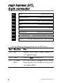
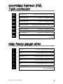
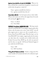
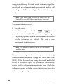
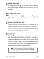
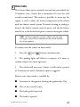
24923
➤Owner’s/Installation
Guide
limited lifetime consumer warranty
Directed Electronics, Inc. (hereinafter "Directed") promises to the original purchaser to
repair or replace with a comparable reconditioned Directed DIY remote start unit if this
Directed DIY remote start unit (hereinafter "Unit"), excluding without limitation, any
remote transmitters or associated accessories, proves defective in materials or workmanship under normal use for the life of the vehicle which the Unit is originally installed.
During this period, so long as the Unit remained installed in the original vehicle, Directed
will at its option, repair or replace this Unit if it is proved defective in workmanship or
material PROVIDED the Unit is returned to Directed's warranty department at One
Viper Way, Vista, CA 92081, along with $20 postage and handling fee, a bill of sale or
other dated proof of purchase bearing the following information: Date of purchase, name
and location of the merchant who sold the Unit, and product description. This warranty
does not cover labor costs for the removal or reinstallation of the Unit. This warranty is
non-transferable and does not apply to any Unit that has been modified or used in a manner contrary to its intended purpose, and this warranty does not cover damage to any Unit
caused by installation or removal of the Unit. This warranty is void if the Unit has been
damaged by accident or unreasonable use, neglect, improper service or other causes not
arising out of defects in materials or workmanship. Directed makes no warranty against
theft of a vehicle or its contents.
THE FOREGOING WARRANTY IS THE EXCLUSIVE PRODUCT WARRANTY,
OTHERWISE, ALL WARRANTIES INCLUDING BUT NOT LIMITED TO
EXPRESS WARRANTY, IMPLIED WARRANTY, WARRANTY OF MERCHANTABILITY, OR FITNESS FOR A PARTICULAR PURPOSE ARE EXPRESSLY
EXCLUDED AND DISCLAIMED TO THE MAXIMUM EXTENT ALLOWED BY
LAW, AND DIRECTED NEITHER ASSUMES NOR AUTHORIZES ANY PERSON
TO ASSUME FOR IT ANY LIABILITY IN CONNECTION WITH THE SALE OF
THE PRODUCT. DIRECTED HAS ABSOLUTELY NO LIABILITY FOR ANY
AND ALL ACTS OF THIRD PARTIES INCLUDING ITS AUTHORIZED DEALERS OR INSTALLERS. SOME STATES DO NOT ALLOW THE LIMITATION ON
HOW LONG AN IMPLIED WARRANTY LASTS, SO THE ABOVE LIMITATION
MAY NOT APPLY TO YOU.
LIMITATION OF DAMAGES AND LIABILITY. CONSUMER'S REMEDY IS LIMITED TO REPAIR OR REPLACEMENT OF THE UNIT, AND IN NO EVENT
SHALL DIRECTED'S LIABILITY EXCEED THE PURCHASE PRICE OF THE
UNIT. IN ANY EVENT, DIRECTED SHALL NOT BE LIABLE FOR ANY DAMAGES INCLUDING, BUT NOT LIMITED TO, ANY DIRECT, INDIRECT, INCIDENTAL, SPECIAL, PUNITIVE OR CONSEQUENTIAL DAMAGES, LOST
PROFITS, LOST SAVINGS, OR, TO THE EXTENT ALLOWED BY APPLICABLE
LAW, DAMAGES RESULTING FROM DEATH OR INJURY ARISING OUT OF
© 2006 Directed Electronics
i
OR IN CONNECTION WITH THE INSTALLATION, USE, IMPROPER USE, OR
INABILITY TO USE, THE PRODUCT, EVEN IF THE PARTY HAS BEEN
ADVISED OF THE POSSIBILITY OF SUCH DAMAGES. SOME STATES DO
NOT ALLOW THE EXCLUSION OF LIMITATION OF INCIDENTAL OR CONSEQUENTIAL DAMAGES, SO THE ABOVE LIMITATIONS OR EXCLUSION
MAY NOT APPLY TO YOU. THE CONSUMER AGREES AND CONSENTS THAT
ALL DISPUTES BETWEEN THE CONSUMER AND DIRECTED SHALL BE
RESOLVED IN ACCORDANCE WITH CALIFORNIA LAWS IN SAN DIEGO
COUNTY, CALIFORNIA.
IMPORTANT NOTE:
This product warranty is automatically void if its date code or serial number is defaced,
missing, or altered.
Make sure you have all of the following information from your dealer:
A clear copy of the sales receipt, showing the following:
➤
➤
➤
ii
Date of purchase
Authorized dealer's company name and address
Item number
© 2006 Directed Electronics
table of contents
limited lifetime consumer warranty . . . . . . . . . . . . . . . . . . . . . . . . . . . . . . . . . . . . . . . . i
what is included . . . . . . . . . . . . . . . . . . . . . . . . . . . . . . . . . . . . . . . . . . . . . . . . . . . . . . 3
installation tools . . . . . . . . . . . . . . . . . . . . . . . . . . . . . . . . . . . . . . . . . . . . . . . . . . . . . . 3
important information . . . . . . . . . . . . . . . . . . . . . . . . . . . . . . . . . . . . . . . . . . . . . . . . . 4
system maintenance . . . . . . . . . . . . . . . . . . . . . . . . . . . . . . . . . . . . . . . . . . . . . . 4
fcc/id notice . . . . . . . . . . . . . . . . . . . . . . . . . . . . . . . . . . . . . . . . . . . . . . . . . . . . 5
warning! safety first . . . . . . . . . . . . . . . . . . . . . . . . . . . . . . . . . . . . . . . . . . . . . . . . . . . 5
main harness (H1), 8-pin connector . . . . . . . . . . . . . . . . . . . . . . . . . . . . . . . . . . . . . . 8
secondary harness (H2), 7-pin connector . . . . . . . . . . . . . . . . . . . . . . . . . . . . . . . . . . . 9
relay heavy gauge wires . . . . . . . . . . . . . . . . . . . . . . . . . . . . . . . . . . . . . . . . . . . . . . . . 9
using LED test probe . . . . . . . . . . . . . . . . . . . . . . . . . . . . . . . . . . . . . . . . . . . . . . . . . 10
installation . . . . . . . . . . . . . . . . . . . . . . . . . . . . . . . . . . . . . . . . . . . . . . . . . . . . . . . . . 11
wiring quick reference guide . . . . . . . . . . . . . . . . . . . . . . . . . . . . . . . . . . . . . . . . . . . 12
step 1 . . . . . . . . . . . . . . . . . . . . . . . . . . . . . . . . . . . . . . . . . . . . . . . . . . . . . . . . 13
step 2 . . . . . . . . . . . . . . . . . . . . . . . . . . . . . . . . . . . . . . . . . . . . . . . . . . . . . . . . 14
step 3 . . . . . . . . . . . . . . . . . . . . . . . . . . . . . . . . . . . . . . . . . . . . . . . . . . . . . . . . 17
step 4 . . . . . . . . . . . . . . . . . . . . . . . . . . . . . . . . . . . . . . . . . . . . . . . . . . . . . . . . 20
step 5 . . . . . . . . . . . . . . . . . . . . . . . . . . . . . . . . . . . . . . . . . . . . . . . . . . . . . . . . 23
step 6 . . . . . . . . . . . . . . . . . . . . . . . . . . . . . . . . . . . . . . . . . . . . . . . . . . . . . . . . 26
step 7 . . . . . . . . . . . . . . . . . . . . . . . . . . . . . . . . . . . . . . . . . . . . . . . . . . . . . . . . 40
step 8 . . . . . . . . . . . . . . . . . . . . . . . . . . . . . . . . . . . . . . . . . . . . . . . . . . . . . . . . 42
step 9 . . . . . . . . . . . . . . . . . . . . . . . . . . . . . . . . . . . . . . . . . . . . . . . . . . . . . . . . 44
step 10 . . . . . . . . . . . . . . . . . . . . . . . . . . . . . . . . . . . . . . . . . . . . . . . . . . . . . . . 45
remote functions . . . . . . . . . . . . . . . . . . . . . . . . . . . . . . . . . . . . . . . . . . . . . . . . . . . . 48
standard configuration . . . . . . . . . . . . . . . . . . . . . . . . . . . . . . . . . . . . . . . . . . . 48
control module programming . . . . . . . . . . . . . . . . . . . . . . . . . . . . . . . . . . . . . . . . . . 50
using your system . . . . . . . . . . . . . . . . . . . . . . . . . . . . . . . . . . . . . . . . . . . . . . . . . . . 53
warning! safety first . . . . . . . . . . . . . . . . . . . . . . . . . . . . . . . . . . . . . . . . . . . . . . 53
locking with remote . . . . . . . . . . . . . . . . . . . . . . . . . . . . . . . . . . . . . . . . . . . . . 55
unlocking with remote . . . . . . . . . . . . . . . . . . . . . . . . . . . . . . . . . . . . . . . . . . . 55
ignition-controlled door locks . . . . . . . . . . . . . . . . . . . . . . . . . . . . . . . . . . . . . . 55
remote start. . . . . . . . . . . . . . . . . . . . . . . . . . . . . . . . . . . . . . . . . . . . . . . . . . . . 55
timer mode . . . . . . . . . . . . . . . . . . . . . . . . . . . . . . . . . . . . . . . . . . . . . . . . . . . . 57
pit stop mode . . . . . . . . . . . . . . . . . . . . . . . . . . . . . . . . . . . . . . . . . . . . . . . . . . . . . . . 58
trunk/auxiliary . . . . . . . . . . . . . . . . . . . . . . . . . . . . . . . . . . . . . . . . . . . . . . . . . . . . . . 59
code hopping ® re-synchronize . . . . . . . . . . . . . . . . . . . . . . . . . . . . . . . . . . . . . . . . . 59
troubleshooting . . . . . . . . . . . . . . . . . . . . . . . . . . . . . . . . . . . . . . . . . . . . . . . . . . . . . 60
glossary of terms . . . . . . . . . . . . . . . . . . . . . . . . . . . . . . . . . . . . . . . . . . . . . . . . . . . . 62
notes . . . . . . . . . . . . . . . . . . . . . . . . . . . . . . . . . . . . . . . . . . . . . . . . . . . . . . . . . . . . . 63
quick reference guide: . . . . . . . . . . . . . . . . . . . . . . . . . . . . . . . . . . . . . . . . . . . . . . . . 65
© 2006 Directed Electronics
1
2
© 2006 Directed Electronics
what is included
➤
Control Module
➤
One 4-Button Remote
➤
8-Pin Main H1 Harness
➤
7-Pin H2 Secondary Harness
➤
6-Pin Relay Heavy Gauge Wires
➤
Shutdown Toggle Safety Switch
➤
Hood Pin Switch
➤
Installation Kit
➤ Razor Knife
➤ CDROM—Do-It-Yourself Installation Video
Additional parts may be required (such as relays or bypass).
installation tools
➤
Digital Multi-Meter
➤
Drill
➤
1
/4 Drill Bit (for hood
pin switch)
➤
Screwdrivers
(Phillips and Flathead)
➤
Wire Stripper
➤
Solder Iron
➤
Electrical Tape
➤
Pliers
➤
Crimping Tool
note: The installation tools listed above may be optional
and those required will vary depending on your vehicle.
© 2006 Directed Electronics
3
important information
Congratulations on the purchase of your remote start keyless
entry system. This system will allow convenient access to your
vehicle with the push of a button, as well as remote start and
other optional features. Properly installed, this system will
provide years of trouble-free operation.
Please take the time to carefully read this User’s Guide in its
entirety and watch the Do-It-Yourself Installation Video
(CDROM) prior to installing your system.
You can print additional or replacement copies of this manual by
accessing the Directed web site at www.designtech-intl.com.
important! If you are not comfortable working with electronics or unfamiliar with the tools required, please contact your local dealer for advice or ask to have the remote
start professionally installed to avoid costly damages.
Failure to properly install the remote starter may result in
property damage, personal injury, or both.
➜ system maintenance
The system requires no specific maintenance. Your transmitter is
powered by a miniature 3-volt battery (type CR2032) that will
last approximately one year under normal use. When the battery
begins to weaken, the operating range will be reduced.
4
© 2006 Directed Electronics
➜ fcc/id notice
This device complies with Part 15 of FCC rules. Operation is
subject to the following conditions: (1) This device may not
cause harmful interference, and (2) This device must accept any
interference received, including interference that may cause
undesirable operation.
Changes or modifications not expressly approved by the party
responsible for compliance could void the user's authority to
operate this device.
warning! safety first
The following safety warnings must be observed at all times:
➤
When properly installed, this system can start the vehicle via
a command signal from the remote control transmitter.
Therefore, never operate the system in an area that does not
have adequate ventilation. The following precautions are the
sole responsibility of the user; however, the following recommendations should be made to all users of this system:
1. Never operate the system in an enclosed or partially
enclosed area without ventilation (such as a garage).
2. When parking in an enclosed or partially enclosed area
or when having the vehicle serviced, the remote start
system must be disabled using the toggle switch.
3. It is the user's sole responsibility to properly handle and
keep out of reach from children all remote control units
© 2006 Directed Electronics
5
to assure that the system does not unintentionally
remote start the vehicle.
4. THE
USER
MUST
INSTALL
A
CARBON
MONOXIDE DETECTOR IN OR ABOUT THE
LIVING AREA ADJACENT TO THE VEHICLE.
ALL DOORS LEADING FROM ADJACENT
LIVING AREAS TO THE ENCLOSED OR
PARTIALLY ENCLOSED VEHICLE STORAGE
AREA MUST AT ALL TIMES REMAIN CLOSED.
➤
Use of this product in a manner contrary to its intended mode
of operation may result in property damage, personal injury,
or death. Except when performing the Safety Check outlined
in this user’s guide, (1) Never remotely start the vehicle with
the vehicle in gear, and (2) Never remotely start the vehicle
with the keys in the ignition. The user will be responsible for
having the neutral safety feature of the vehicle periodically
checked, wherein the vehicle must not remotely start while
the car is in gear. This testing should be performed by an
authorized Directed dealer in accordance with the Safety
Check outlined in this product installation guide. If the
vehicle starts in gear, cease remote start operation immediately
and consult with the Dealer to fix the problem immediately.
➤
After the remote start module has been installed, test the
remote start module in accordance with the Safety Check
outlined in this installation guide. If the vehicle starts when
performing the Neutral Safety Shutdown Circuit test, the
6
© 2006 Directed Electronics
remote start unit has not been properly installed. The remote
start module must be removed or properly reinstalled so that
the vehicle does not start in gear. OPERATION OF THE
REMOTE START MODULE IF THE VEHICLE STARTS
IN GEAR IS CONTRARY TO ITS INTENDED MODE
OF OPERATION. OPERATING THE REMOTE START
SYSTEM
UNDER THESE
CONDITIONS
MAY
RESULT IN PROPERTY DAMAGE OR PERSONAL
INJURY. IMMEDIATELY CEASE THE USE OF THE
UNIT AND REPAIR OR DISCONNECT THE
INSTALLED REMOTE START MODULE. DIRECTED
WILL NOT BE HELD RESPONSIBLE OR PAY FOR
INSTALLATION OR REINSTALLATION COSTS.
© 2006 Directed Electronics
7
main harness (H1),
8-pin connector
H1/1
___ BLUE
H1/2
___ VIOLET/WHITE
H1/3
___ BROWN
H1/4
___ GRAY
H1/5
___ BLACK
H1/6
___ WHITE/BLUE
H1/7
___ LT. GREEN/BLACK
H1/8
___ WHITE
(-) 200mA Status Output
Tachometer Input (optional)
(+) Brake Switch Shutdown Input
(-) Hood Pin Shutdown Input
Ground
(-) Remote Start Activation Input
Factory Alarm Disarm/RAP Cancellation
(+/- selectable) Parking Light Flash Output (optional)
Use the following wiring guidelines for the H1 harness.
Pin # Wire Color
Note
H1/1 Blue
Required when using a bypass module or a
(-) 3rd ignition output.
This wire must be connected.
Use if the vehicle is equipped with a factory
alarm disarm or for retained accessory power
cancellation (RAP).
H1/3 Brown
H1/7 Lt. Green/
Black
8
© 2006 Directed Electronics
secondary harness (H2),
7-pin connector
H2/1
___ RED/WHITE
H2/2
___ WHITE/BLACK
Lock #87A Normally Closed
H2/3
___ GREEN/BLACK
Lock #30 Common Output
H2/4
___ VIOLET/BLACK
Lock #87A Normally Open (Input) 15 A
H2/5
___ BROWN/BLACK
UnLock #87 Normally Closed
H2/6
___ BLUE/BLACK
Unlock #30 Common Output
H2/7
___ VIOLET
(-) Channel 2 (auxiliary channel ie: trunk)
Unlock #87A Normally Open (Input) looped back
to H2/4
relay heavy gauge wires
1
___ VIOLET
(+) (30A) Output to Starter Circuit
2
___ RED
(+) (30A) High Current 12V Input
3
___ ORANGE
4
___ PINK
5
___ RED
6
___ PINK/WHITE
© 2006 Directed Electronics
(+) (30A) Output to Accessory Circuit
(+) (30A) Output to Ignition Circuit
(+) (30A) High Current 12V Input
(+) Output for 2nd Ignition
(not programmable)
9
using LED test probe
note: Do not use this test probe on computerized equipment or on the tachometer wiring as damage can result.
To use the LED test probe:
1. Remove the protective cover off the probe tip. Save the
protective cover for reinstallation on the probe tip when
the LED tester is not being used.
2. Connect the Black clip to a good chassis ground.
3. Connect the Red clip to a good +12V source. Both the
Red and Green LEDs should be illuminated dimly.
4. If a positive voltage source is probed, the Red LED will
illuminate brightly, and the Green LED will extinguish.
5. If a negative source is probed the Green LED will illuminate brightly and the Red LED will extinguish.
Alternate procedure to use the LED test probe (only for use on
probing positive voltage wires):
1. Remove the protective cover off the probe tip. Save the
protective cover for reinstallation on the probe tip when
the LED tester is not being used.
2. Connect the Black clip to a good chassis ground.
3. If a positive voltage source is probed, the Red LED will
illuminate brightly.
10
© 2006 Directed Electronics
installation
Be sure to read this section thoroughly and view the Do-ItYourself Installation CDROM video in its entirety before
starting the installation. Pay special attention to all warnings to
prevent personal injury or damage to your vehicle.
www.designtech-intl.com)
Visit our 24-hour technical Web site (w
to get a vehicle-specific wiring guide prior to starting this installation. Have on hand your crash code number when contacting
tech support or visiting the web site. During the installation if
you are unable to answer your questions on the Web site, call 1800-477-1382 (to get hours of phone operation) for live technical assistance.
warning! This system is intended for automatic, fuel-injected vehicles only. Installation
in any other vehicle is contrary to its intended use.
warning! On vehicles with air bags or supplemental restraint systems (SRS) you may
notice a bright yellow tube with small wires
in it marked SRS underneath the steering
column near the key cylinder. DO NOT
tamper or unplug these for any reason to
prevent costly damages to your vehicle or
personal injury. Tampering may cause
unintended deployment of airbags.
warning! Verify that the vehicle is set to
park and that the parking brake is set
before beginning installation.
© 2006 Directed Electronics
11
12
WHITE - DOOR LOCK
GREEN - DOOR UNLOCK
RED - IGNITION CONTROL
RED/WHITE - (-) Channel 2
WHITE/BLACK - Lock #87 Normally Closed
GREEN/BLACK - Lock #30 Common (Output)
VIOLET/BLACK - Lock #87 Normally Open Input 15A Fused
BROWN/BLACK - Lock #87A Normally Closed
BLUE/BLACK - Unlock #30 Common (Output)
VIOLET - Lock #87 Normally Open Input (looped to VIOLET/BLACK)
H2
Heavy Gauge
Wires
H1
wiring quick reference guide
© 2006 Directed Electronics
➜ step 1
Ground Wire
The BLACK (H1/5) wire on the main 8-pin harness is ground.
First strip back a ¾-inch section of the insulation off the BLACK
wire and crimp a ring terminal (not provided) to that wire.
Locate a clean, paint-free metal surface in the drivers kick panel.
Using a self-tapping screw, drill the screw with the ring terminal
to the metal area. Once screwed down, pull on the wire to ensure
a good connection.
note: More problems are attributed to poor ground connections than any other cause. Take extra care to ensure
the ground is a clean metal-to-metal contact and secure.
SELF-TAPPING
BOLT OR SCREW
GROUND
WIRE
DIA-591
NOTE: REMOVE ANY PAINT
BELOW RING CONNECTOR
© 2006 Directed Electronics
RING
TERMINAL
13
➜ step 2
Constant Power and Ignition wires
Almost all power and ignition wires can be found behind the key
cylinder under the lower drivers side dash panel. Using the
appropriate hand tools, remove the lower dash panel using care
not to break any parts. If the panel does not come off easily
check for any additional screws you may have missed.
warning! On vehicles with air bags or supplemental restraint systems (SRS) you may
notice a bright yellow tube with small wires
in it marked SRS underneath the steering
column near the key cylinder. DO NOT
tamper or unplug these for any reason to
prevent costly damages to your vehicle or
personal injury. Tampering may cause
unintended deployment of airbags.
Once the lower dash panel has been removed, locate the ignition
harness at the back of the key cylinder. This is usually a group of
thicker wires. With the ignition harness exposed, use your LED
tester to find your power and ignition wires.
Place the black lead of the test probe to a clean metal surface in
14
© 2006 Directed Electronics
the kick panel area and secure it. Probe one of the thicker gauge
wires. The color and identity of your specific vehicle wiring can
be obtained at www.designtech-intl.com. With the key in the off
position, test the suspect wire. The constant power wire will illuminate the Red LED on the test probe.
warning! Before making any connection
to constant battery power make sure that
the two green 30 amp fuses are removed
from the fuse holders on the two thick red
wires (heavy gauge wires). Failure to do so
may cause fire or shorting of sensitive electrical components.
30 A
fuses
Control
Module
RED heavy
gauge wires
Once the constant power wire has been identified, solder the two
heavy gauge RED wires from the control module (relay heavy
gauge) to it and wrap the connection with electrical tape.
note: If the vehicle has two constant power wires, utilize
both constant power wires. Connect one of the heavy
gauge RED wires to one of the constant power wires and
the other heavy gauge RED wire to the other constant
power wire.
With the test probe black lead still in the kick panel, locate the
ignition wire in the same location. It will test differently than
© 2006 Directed Electronics
15
constant (+)12 volts. Locate the suspected wire using the
www.designtech-intl.com Web site and place the red lead of the
test probe on the suspected wire. With the key in the off position
the probes LED will be off. Turn the key to the on position and
the LED tester will illuminate Red. Now watching your probe,
turn the key to the crank position. If the LED extinguishes this
is not an ignition wire but an accessory wire. If the wire tests
correctly, solder the thick PINK (4) wire of the heavy gauge wires
to it and wrap the connection with electrical tape.
If the vehicle requires more than one ignition as per the Web site
information follow the same test procedure and solder the thick
PINK/WHITE (6) wire of the heavy gauge wires to it and wrap
the connection with electrical tape. If your vehicle has only 1
ignition source, secure the PINK/WHITE out of the way.
If your vehicle requires more than two ignitions, an additional
relay (not provided) is required. Refer to the diagram below.
16
© 2006 Directed Electronics
+12 VDC CONSTANT (FUSED 20A)
2nd IGNITION RELAY
(NOT PROVIDED)
TO 2nd IGNITION
87
86
GROUND
87A
30
85
TO 2nd IGNITION
+12 VDC CONSTANT (FUSED 20A)
3rd IGNITION RELAY
(NOT PROVIDED)
PINK/WHITE (+) OUTPUT
TO 2nd IGNITION
87
86
87A
30
GROUND
85
TO 3rd IGNITION
➜ step 3
Accessory and Starter wires
The starter and accessory wires will be located in the same harness
as the ignition and constant power.
To find the accessory wire leave the LED tester black lead
connected to the metal ground, take the red lead and probe the
wire suspected to be the accessory. With the key off, your test
probe’s LED should be off. Turn the key to the on position and
the LED tester should be illuminated Red. Now turn the key to
the crank position. If you have the correct accessory wire the LED
will extinguish while the starter is cranking and return once the
key returns to the on position. If the wire tests correctly, strip the
© 2006 Directed Electronics
17
insulation off a small portion and solder the thick ORANGE (3)
wire of the heavy gauge wire and wrap it with electrical tape.
If your vehicle requires more than one accessory, an additional
relay (not provided) is required. Refer to the diagram below.
+12 VDC CONSTANT (FUSED 20A)
ACCESSORY RELAY
(NOT PROVIDED)
87
TO ACCESSORY
86
GROUND
87A
30
85
TO ACCESSORY
+12 VDC CONSTANT (FUSED 20A)
2nd ACCESSORY RELAY
(NOT PROVIDED)
ORANGE (+) 30A OUTPUT TO
ACCESSORY CIRCUIT
87
86
GROUND
87A
30
85
TO 2nd ACCESSORY
Now that the accessories have been located, find the wire
suspected to be the starter wire according to the web information
on your vehicle. Place the red lead of your LED tester on the
18
© 2006 Directed Electronics
wire. With the key in the off position the LED tester should be
extinguished in all key positions except the crank position. In
the crank position your LED tester should illuminate Red, and
will extinguish when the starter disengages.
note: Always check the Web site information on your
vehicle for warnings regarding the starter wire and check
engine lights. Some vehicles will trip a check engine light
if the starter wire is cut.
Once you locate the starter wire, cut the wire in half (ccheck the
web information before cutting) and try to start the vehicle. If
the vehicle does not start, the correct wire has been identified.
Reconnect both ends the starter wire while soldering the thick
VIOLET (1) wire of the heavy gauge wires to it and wrap the
connection with electrical tape.
Many Nissan vehicles have two starter wires. A relay (not provided)
is required to hook up the additional starter wire. Refer to the
diagram below.
© 2006 Directed Electronics
19
+12 VDC CONSTANT (FUSED 20A)
STARTER RELAY
(NOT PROVIDED)
87
TO STARTER
86
GROUND
87A
30
85
TO STARTER
+12 VDC CONSTANT (FUSED 20A)
2nd STARTER RELAY
(NOT PROVIDED)
VIOLET (+) OUTPUT
TO STARTER
87
86
GROUND
87A
30
85
TO 2nd STARTER
➜ step 4
Safety Shutdown Wires
warning! These wires are meant to protect
the vehicle and anyone near the vehicle.
They must be connected appropriately to
prevent damage to the vehicle and possible
bodily injury. Failure to properly install
these wires may cause the vehicle to lunge if
remote started while in gear.
With all ignition wires properly connected, find the appropriate
safety shutdown wires. These are the brake wire and hood pin wires.
First locate the factory brake wire using your test probe. Find the
switch at the top of the metal arm coming off the brake pedal.
There are usually two wires connected to that switch. Locate the
20
© 2006 Directed Electronics
wire color according to the web information. With your black
test probe lead still in the kick panel, probe the suspected wire
with the red lead of your test probe. With the brake pedal at rest
the LED tester should be extinguished. While watching the test
probe, depress the brake pedal. The LED tester should illuminate Red. Once you have located the correct brake wire, solder
the small BROWN (H1/3) wire of the main harness to it and
wrap the connection with electrical tape.
warning! Do not use the vehicle until you
confirm the operation of the brake shutdown.
Installing the hood pin switch requires drilling a ¼-inch hole in the
metal lip under the hood. Choose a location that will allow the pin
switch to be depressed when the hood is closed. The pin switch has
a spade connector on the bottom for the wire connection.
© 2006 Directed Electronics
21
Place the wire with the spade connector onto the pin switch and
run the wire into the vehicle’s passenger compartment through a
factory rubber grommet. Using a sharp, pointed object poke a
hole into the grommet and attach the wire to the object with
electrical tape. Pull the wire through the grommet taking extra
care to keep the wire away from any moving parts or anything
that will generate extreme heat. Once the wire is run into the
vehicle and secured from any moving parts, solder the wire to
the GRAY (H1/4) wire of the main harness and wrap the
connection with electrical tape.
warning! This wire MUST be connected. Do
not use the vehicle until you confirm the operation of the hood pin shutdown. Improper
operation could result injury or death.
The bypass toggle switch is designed to bypass the remote start
in an emergency or to disable the remote start functions
temporarily (i.e., for service on the vehicle or when parking in an
enclosed area). This switch is to be mounted in an easily accessible location in the passenger compartment.
Connect the toggle switch as shown below. The Gray (H1/4)
wire to the hood pin switch, and the Black wire from the switch
to ground. The toggle switch must be in the Off position for
normal operation.
22
© 2006 Directed Electronics
HOOD PIN SWITCH OPEN WHEN HOOD IS CLOSED
TO GRAY (H1/5) WIRE
ON
CONTROL MODULE
HOOD PIN SWITCH CONNECTOR
GRAY WIRE
BYPASS
TOGGLE
SWITCH
BLACK WIRE
BYPASSED WHEN CLOSED
➜ step 5
Parking light flash
There are several different types of parking light circuits. The
following description is for a standard positive-triggered parking
light circuit, only. If the web vehicle information suggests a (-)
parking light circuit, the fusible jumper (under the sliding door
on the control module) must be moved to the opposite position.
The default position for this jumper is for a positive parking
light. Refer to the LED test probe procedures if you have a negative
parking light circuit.
note: When parking lights are connected, they will flash
for the whole time that remote start is active.
© 2006 Directed Electronics
23
important! If the WEB vehicle information requires
using resistors for parking lights, contact Directed
Technical Support.
Using the web information on the vehicle, locate the suspected
wire and place the red lead of the test probe to a constant (+)12
volt source and secure it. Leave the black test probe lead in the
kick panel,. Probe the suspected wire with the test probe. With
the switch in the off position the test probe should have both
LEDs illuminated dimly. While watching the test probe LEDs,
turn the switch to the parking light position. The test probe’s
green LED should illuminate and the red LED should extinguish. While testing the suspected wire, run the dash dimmer
light control up and down—the voltage should NOT vary (the
green LED should stay illuminated and the red LED should stay
off ). If the voltage does vary, continue probing to find the
correct wire.
Once you have identified the correct wire, solder the WHITE
(H1/8) wire of the main harness to it and wrap the connection
with electrical tape.
24
© 2006 Directed Electronics
© 2006 Directed Electronics
25
➜ step 6
Door Locks
The system comes with a built in relay pack for door lock operation. When attempting to interface the power door locks with
your system it is important to understand that there are multiple
types of door locking systems in today's vehicles. To determine
your vehicle’s power door lock system, check the web information
on your vehicle.
If your door lock system is a different type than described in this
guide, go to www.designtech-intl.com (On-Line Tech Support,
Tech Tips) to download the door lock systems guide. This guide
identifies the type of system for your vehicle. With the built in door
lock relays you can properly interface the power locks with your
keyless entry/remote start system. If you are unable to identify your
door lock system with the web information please contact Directed
Technical Support.
Although there are numerous types of door lock circuits, the
most common is the negative triggered door lock system (Type
B). If your vehicle has a negative triggered door lock system,
follow the steps below. If your vehicle has any other type of door
lock system then, the easiest way to determine which type of
door lock system you are working with is to remove the master
locking switch itself, which is usually on the driver’s door or on
the center console. Once you have determined which type of
factory door lock circuit you are working with, and the color
codes of the switch wires to be used, you can usually simplify the
26
© 2006 Directed Electronics
installation by locating the same wires in the vehicle’s kick panel.
If no central locking switch is found, the installation may require
a door lock actuator.
note: Always retest the wires in the kick panel to be sure
they function the same way as the wires on the switch.
There are eight common types of door lock circuits (some vehicles use more unusual systems):
■ Type A: Three-wire (+) pulse controlling factory lock relays.
Most GM, some Ford and Chrysler, 1995 Saturn, some new
VW, newer BMW.
■ Type B: Three-wire (-) pulse controlling factory lock relays.
Most Asian vehicles, early Saturn, some BMW and Porsche.
■ Type C: Direct-wired reversing-polarity switches. The switches are wired directly to the motors. This type of system has no
factory relays. Most Fords, many GM two-door cars and trucks,
many Chryslers.
■ Type D: Adding one or more aftermarket actuators. These
include slave systems without an actuator in the driver’s door,
but with factory actuators in all the other doors. Type D also
includes cars without power locks, which will have actuators
added. All Saabs before 1994, all Volvo except 850i, all pre-1997
Subarus, most Isuzus, and many Mazdas. Some mid-eighties
Nissans, pre-1985 Mercedes-Benz and Audi.
■ Type E: Electrically-activated vacuum systems. The vehicle
© 2006 Directed Electronics
27
must have a vacuum actuator in each door. Make sure that locking the doors from the driver's or passenger side using the key
activates all the actuators in the vehicle. This requires a slight
modification to the door lock harness. Mercedes-Benz and Audi
1985 and newer.
■ Type F: One-wire system - cut to lock, ground to unlock. This
system is found in late-model Nissan Sentras, some Nissan
240SX, and Nissan 300ZX 1992 and later. It is also found in
older Mitsubishis, and some early Mazda MPV’s.
■ Type G: Positive (+) multiplex. This system is most commonly found in Ford, Mazda, Chrysler and GM vehicles. The door
lock switch or door key cylinder may contain either one or two
resistors.
■ Type H: Negative (-) multiplex. The system is most commonly found in Ford, Mazda, Chrysler and GM vehicles. The door
lock switch or door key cylinder may contain either one or two
resistors.
at the door lock switch
■ Three-wire switches will have either a constant ground input or
a constant (+)12V input, along with the pulsed lock and unlock
outputs to the factory relays.
■ Many BMW’s and VW’s have no external switch. The switches are inside the actuator, and instead of pulsing, the proper
wires will flip-flop from (+)12V to (-) ground as the door locks
are operated.
■ Direct-wired switches will have a (+)12V constant input and one
or two (-) ground inputs, along with two output leads going
28
© 2006 Directed Electronics
directly to the lock motors.
type A: positive-triggered, relay-driven system
FACTORY LOCK
SWITCH
UNLOCK
LOCK
H2/2
LOCK
RELAY
#87
#30A
WHITE/BLACK
NOT USED
H2/3
GREEN/BLACK
LOCK #30 COMMON (OUTPUT)
H2/4
VIOLET/BLACK
LOCK #87 NORMALLY OPEN (INPUT)
H2/5
BROWN/BLACK
NOT USED
VEHICLE (+)
LOCK TRIGGER
CIRCUIT
#87A
15A
#87
UNLOCK
RELAY
#30A
H2/6
BLUE/BLACK
UNLOCK #30 COMMON (OUTPUT)
#87A
H2/7
VIOLET
© 2006 Directed Electronics
VEHICLE FUSED
+12 VOLT
CONSTANT
VEHICLE (+)
UNLOCK TRIGGER
CIRCUIT
TO FACTORY
RELAYS
UNLOCK #87 NORMALLY OPEN (INPUT)
29
type B: negative-triggered, relay-driven system
This system is common in many Toyota, Nissan, Honda, and
Saturn models, as well as Fords with the keyless-entry system
(some other Fords also use Type B).
The switch will have three wires on it, and one wire will test
ground all the time. One wire will pulse (-) when the switch
locks the doors, and the other wire will pulse (-) when the switch
unlocks the doors. This type of system is difficult to mistake for
any other type.
FACTORY LOCK
SWITCH
LOCK
LOCK
RELAY
#87
WHITE/BLACK
NOT USED
H2/3
GREEN/BLACK
LOCK #30 COMMON (OUTPUT)
H2/4
VIOLET/BLACK
LOCK #87A NORMALLY OPEN (INPUT)
H2/5
BROWN/BLACK
NOT USED
TO CHASSIS
GROUND
15A
#30A
H2/6
BLUE/BLACK
UNLOCK #30 COMMON (OUTPUT)
#87A
H2/7
30
VEHICLE (-)
LOCK TRIGGER
CIRCUIT
#87A
#87
UNLOCK
RELAY
#30A
H2/2
UNLOCK
VIOLET
VEHICLE (-)
UNLOCK TRIGGER
CIRCUIT
TO FACTORY
RELAYS
UNLOCK #87 NORMALLY OPEN (INPUT)
© 2006 Directed Electronics
type C: direct-wired, reversing-polarity system
DOOR LOCK SWITCH
(+) 12V
LOCK
UNLOCK
X CUT X
X CUT X
LOCK
RELAY
#87
#30A
H2/2
WHITE/BLACK
LOCK #87A NORMALLY CLOSED
H2/3
GREEN/BLACK
LOCK #30 COMMON (OUTPUT)
H2/4
VIOLET/BLACK
LOCK #87 NORMALLY OPEN (INPUT)
H2/5
BROWN/BLACK
UNLOCK #87A NORMALLY CLOSED
MOTOR
LOCK WIRES
#87A
15A
#87
UNLOCK
RELAY
MOTOR
UNLOCK WIRES
#30A
H2/6
BLUE/BLACK
UNLOCK #30 COMMON (OUTPUT)
H2/7
VIOLET
UNLOCK #87 NORMALLY OPEN (INPUT)
+12V CONSTANT
(15A CAPABLE)
#87A
testing reversing polarity systems
Use these instructions if the power door lock switch has four or
five heavy-gauge wires. This type of switch has two outputs that
rest at (-) ground.
important: To interface with these systems, you must cut
two switch leads. The relays must duplicate the factory
door lock switches’ operation. The master switch will
have one or two ground inputs, one (+)12V input, and
two switch outputs going directly to the slave switch and
through to the motors. These outputs rest at (-) ground.
The lock or unlock wire is switched to (+)12V, while the
other wire is still grounded, thus completing the circuit
and powering the motor. This will disconnect the switch
from the motor before supplying the motor with (+)12V,
avoiding sending (+)12V directly to (-) ground.
© 2006 Directed Electronics
31
It is critical to identify the proper wires and locate the master
switch to interface properly. Locate wires that show voltage when
the switch is moved to the lock or unlock position. Cut one of
the suspect wires and check operation of the locks from both
switches. If one switch loses all operation in both directions then
you have cut one of the correct wires and the switch that is
entirely dead is the master switch. If both switches still operate
in any way and one or more door motors have stopped
responding entirely, you have cut a motor lead. Reconnect it and
continue to test for another wire. Once both wires have been
located and the master switch identified, cut both wires and
interface as described in the following paragraphs.
caution: If these wires are not connected properly, you
will send (+)12V directly to (-) ground, possibly damaging the alarm or the factory switch.
■ H2/2 WHITE/BLACK: Once both door lock wires are
located and cut, connect the white/black wire to the master
switch side of the lock wire. The master switch side will show
(+)12V when the master switch is operated to the lock position
and (-) ground when the master switch is in the middle position.
■ H2/3 GREEN/BLACK: Connect the green/black wire to
the other side of the lock wire. This is the motor side of the lock
wire and it goes to the lock motor through the slave switch.
32
© 2006 Directed Electronics
■ H2/4 VIOLET/BLACK: This wire must be connected to
a constant (+)12 volts. The best connection point for this wire is
the constant (+)12V supply for the door lock switch*, or directly to the positive (+) battery post with a fuse at the battery post.
*note: Except in GM cars with retained accessory power
(RAP). In these vehicles, the (+)12V feed to the door lock
switches is turned off if the doors are closed for any length
of time.
note: Most direct-wired power lock systems require 20-30
amps of current to operate. Connecting the violet/black
wire to a poor source of voltage will keep the door locks
from operating properly.
■ H2/5 BROWN/BLACK: Connect the brown/black wire to
the master switch side of the unlock wire. The master switch side
will show (+)12V when the master switch is in the unlock position
and (-) ground when the master switch is in the middle position.
■ H2/6 BLUE/BLACK: Connect the blue/black wire to the
other side of the unlock wire.
■ H2/7 VIOLET: This wire must be connected to a constant
(+)12 volts. The best connection point for this wire is the constant (+)12V supply for the door lock switch*, or directly to the
positive (+) battery post with a fuse at the battery post. (See both
notes above.)
© 2006 Directed Electronics
33
type D: adding one or more after-market actuators
Vehicles without factory power door locks require the installation of one actuator per door. This requires mounting the door
lock actuator inside the door. Other vehicles may only require
one actuator installed in the driver's door if all door locks are
operated when the driver's lock is used.
LOCK
RELAY
#87
#30A
H2/2
WHITE/BLACK
LOCK #87A NORMALLY CLOSED
CHASSIS
GROUND
H2/3
GREEN/BLACK
LOCK #30 COMMON (OUTPUT)
GREEN
H2/4
VIOLET/BLACK
LOCK #87 NORMALLY OPEN (INPUT)
H2/5
BROWN/BLACK
UNLOCK #87A NORMALLY CLOSED
#87A
CHASSIS
GROUND
15A
#87 #30A
UNLOCK
RELAY
BLUE
H2/6
BLUE/BLACK
UNLOCK #30 COMMON (OUTPUT)
H2/7
VIOLET
UNLOCK #87 NORMALLY OPEN (INPUT)
+ 12V FUSED
7.5A /MOTOR
#87A
note: Adding door lock actuators can be complicated.
Please contact Directed technical support prior to
attempting the addition of actuators.
34
© 2006 Directed Electronics
type E: electrically-activated vacuum
This system is found in Mercedes-Benz and Audi 1985 and
newer. The door locks are controlled by an electrically activated
vacuum pump. The control wire will show (+)12V when doors
are unlocked and (-) ground when locked.
note: The system must be programmed for 3.5-second
door lock pulses, and the violet jumper between the #87
lock terminal and the #87 unlock terminal must be cut.
Contact Directed technical support. See Programming section.
LOCK
#87
#30
H2/2
WHITE/BLACK
LOCK #87A NORMALLY CLOSED
H2/3
GREEN/BLACK
LOCK #30 COMMON (OUTPUT)
TRIGGER WIRE IN CAR
#87a
X
H2/4
VIOLET/BLACK
CHASSIS
GROUND
LOCK #87 NORMALLY OPEN (INPUT)
X
H2/5
CUT
X
CUT
BROWN/BLACK
UNLOCK #87A NORMALLY CLOSED
X
UNLOCK
#87
#30
#87a
H2/6
BLUE/BLACK
UNLOCK #30 COMMON (OUTPUT)
H2/7
VIOLET
UNLOCK #87 NORMALLY OPEN (INPUT)
TO ELECTRIC
VACUUM PUMP
15A
© 2006 Directed Electronics
TO 12 VOLTS
35
type F: one-wire system (cut to lock, ground to unlock)
This type of door lock system usually requires a negative pulse
to unlock, and cutting the wire to lock the door. (With some
vehicles, these are reversed.) It is found in the late-model Nissan
Sentras, some Nissan 240SX, Nissan 300ZX 1992 and later. It is
also found in some Mazda MPV's.
note: The violet jumper between the #87 lock terminal
and the #87 unlock terminal must be cut.
FACTORY SWITCH
CONNECTION
WHEN DOORS
ARE LOCKED
LOCK
RELAY
#87
H2/2
WHITE/BLACK
LOCK #87A NORMALLY CLOSED
H2/3
GREEN/BLACK
LOCK #30 COMMON (OUTPUT)
CONNECTION
WHEN DOORS
ARE UNLOCKED
X
#30A
CUT
#87A
X
H2/4
VIOLET/BLACK
NOT USED
H2/5
BROWN/BLACK
UNLOCK #87A NORMALLY CLOSED
H2/6
BLUE/BLACK
UNLOCK #30 COMMON (OUTPUT)
H2/7
VIOLET
UNLOCK #87 NORMALLY OPEN (INPUT)
X
UNLOCK
RELAY
#87 #30A
#87A
CUT
X
FACTORY LOCK
MODULE
15A
36
CHASSIS
GROUND
© 2006 Directed Electronics
type G: positive (+) multiplex
This system is most commonly found in Ford, Mazda, Chrysler
and GM vehicles. The door lock switch or door key cylinder
may contain either one or two resistors.
SINGLE-RESISTOR TYPE: If one resistor is used in the door
lock switch/key cylinder, the wire will pulse (+)12V in one direction and less than (+)12V when operated in the opposite direction.
TWO-RESISTOR TYPE: If two resistors are used in the factory
door lock switch/key cylinder, the switch/key cylinder will read
less than (+)12V in both directions.
DETERMINING THE PROPER RESISTOR VALUES: To
determine the resistor values, the door lock switch/key cylinder
must be isolated from the factory door lock system. For testing, use
a calibrated digital multimeter that is set to ohms.
note: To ensure an accurate resistance reading, do not
touch the resistor or leads during testing.
note: Please refer to the Door Locking Systems document
on www.designtech-intl.com (On-Line Tech Support,
Tech Tips) for complete resistor test procedure and additional information for multiplexed door locks.
1.
Cut the output wire from the door lock switch/key cylinder in half.
2.
Test with the meter from the switch side of the cut door lock
switch/key cylinder wire to a reliable constant (+)12V source.
Some good constant (+)12V references are the power input
source to the door lock switch/key cylinder, the ignition switch
© 2006 Directed Electronics
37
power wire, or the (+) terminal of the battery.
3.
Operate the door lock switch/key cylinder in both directions to
determine the resistor values. If the multimeter displays zero resistance in one direction, no resistor is needed for that direction.
4.
Once the resistor value(s) is determined, refer to the wiring diagram for proper wiring.
(+)12V
CONSTANT FUSED
LOCK
RELAY
UNLOCK
RELAY
#87
#30
H2/2
WHITE/BLACK
NOT USED
H2/3
GREEN/BLACK
LOCK #30 COMMON (OUTPUT)
H2/4
VIOLET/BLACK
LOCK #87A NORMALLY OPEN (INPUT)
H2/5
BROWN/BLACK
NOT USED
LOCK RESISTOR
(IF REQUIRED)
15A
#30
H2/6
BLUE/BLACK
UNLOCK #30 COMMON (OUTPUT)
#87A
H2/7
UNLOCK
LOCK
#87A
#87
DOOR LOCK SWITCH/
KEY CYLINDER
VEHICLE FUSED
+12 VOLT CONSTANT
UNLOCK RESISTOR
(IF REQUIRED)
BCM
VIOLET
UNLOCK #87 NORMALLY OPEN (INPUT)
VIOLET & VIOLET/BLACK ARE COMMON AT FUSE HOLDER
type H: negative (-) multiplex
The system is most commonly found in Ford, Mazda, Chrysler
and GM vehicles. The door lock switch or door key cylinder
may contain either one or two resistors.
SINGLE-RESISTOR TYPE: If one resistor is used in the door lock
switch/key cylinder, the wire will pulse ground in one direction and
resistance to ground when operated in the opposite direction.
38
© 2006 Directed Electronics
TWO-RESISTOR TYPE: If two resistors are used in the factory
door lock switch/key cylinder, the door lock switch/key cylinder
will read resistance to ground in both directions.
DETERMINING THE PROPER RESISTOR VALUES: To
determine the resistor values, the door lock switch/key cylinder
must be isolated from the factory door lock system. For testing, use
a calibrated digital multimeter that is set to ohms.
note: To ensure an accurate resistance reading, do not
touch the resistor or leads during testing.
note: Please refer to the Door Locking Systems document
on www.designtech-intl.com (On-Line Tech Support,
Tech Tips) for complete resistor test procedure and additional information for multiplexed door locks.
1.
Cut the output wire from the door lock switch/key cylinder in half.
2.
Test with the meter from the switch side of the cut door lock
switch/key cylinder wire to a reliable ground source. Some good
ground references are the ground input source to the door lock
switch/key cylinder or the battery ground.
3.
Operate the door lock switch/key cylinder in both directions to
determine the resistor values. If the multimeter displays zero resistance in one direction, no resistor is needed for that direction.
4.
Once the resistor value(s) is determined, refer to the wiring diagram for proper wiring.
© 2006 Directed Electronics
39
CHASSIS
GROUND
LOCK
RELAY
#87 #30
H2/2
WHITE/BLACK
NOT USED
H2/3
GREEN/BLACK
LOCK #30 COMMON (OUTPUT)
H2/4
VIOLET/BLACK
LOCK #87A NORMALLY OPEN (INPUT)
H2/5
BROWN/BLACK
NOT USED
#87A
LOCK
UNLOCK
RELAY
#30
#87A
H2/6
BLUE/BLACK
H2/7
VIOLET
UNLOCK #87 NORMALLY OPEN (INPUT)
VIOLET & VIOLET/BLACK ARE COMMON AT FUSE HOLDER
UNLOCK #30 COMMON (OUTPUT)
UNLOCK
LOCK RESISTOR
(IF REQUIRED)
15A
#87
DOOR LOCK SWITCH/
KEY CYLINDER
TO CHASSIS
GROUND
UNLOCK RESISTOR
(IF REQUIRED)
BCM
➜ step 7
Engine monitoring (voltage—default setting)—optional
During remote start the system will need to know if the engine
is running. The module does this by monitoring the voltage of
the vehicle’s electrical system (or the tachometer-see next topic).
When the vehicle is not running the electrical system is approximately 12 volts. The system detects the engine running when
the voltage increases by 1 volt above the resting battery voltage.
The remote start system monitors the increase to prevent the
starter from cranking when the vehicle is already running.
If the remote start system sees the voltage drop by 1/2V the
system assumes the engine is not running and will shut down the
Ignition/Accessory circuit.
40
© 2006 Directed Electronics
On some vehicles the electrical system has too low of a voltage
variance for the remote start module to see. In this case the
engine will start but will only run for about ten seconds. If this
is the case, it will be necessary to use the tachometer.
Engine monitoring (tachometer)
warning! In the following procedure do
not wear loose clothing that could get
entangled in rotating engine components.
Ensure that your hands and arms are well
clear of these rotating components when
working in the engine compartment.
Lastly, ensure that all wires and tools are
clear of falling into or entanglement with
these rotating components.
note! In the following procedure do NOT use a test light.
Use of this type of tester can cause grounding of sensitive
electrical components causing damage, including damage
to the power train control module. A digital multi-meter
is required to test for this wire.
Identify the suspect wire according to the web information.
© 2006 Directed Electronics
41
Place the black lead of the multi-meter on the negative battery
post and secure it. Put the multi-meter in the AC position and
connect the probe to the suspect wire with the red lead of the
multi-meter. Then start the vehicle with the key. With the
engine at idle the multi-meter should read between .65 volts to
1.5 volts.
Have a second person press the gas pedal to increase the RPMs
and watch the meter display. When the RPMs increase the
voltage should rise slightly. (Not all tachometer outputs will rise
when the engine RPMs increase). Once the correct tachometer
wire has been identified, turn the vehicle off.
Run the Violet/White (H1/2) wire from the main connector
through the firewall into the engine compartment along side the
hood pin wire. Use the same procedure as with the hood pin
wire and pull the wire through the grommet taking extra care to
keep it away from any moving parts or anything that will
generate extreme heat. Once the wire is run into the engine
compartment, strip a small portion of insulation off the
tachometer wire and solder it to the Violet/White wire and wrap
the connection with electrical tape. Pull on the wire to ensure a
good connection.
note! For the programming of the tachometer, refer to
the Control Module Programming discussion.
➜ step 8
Factory Alarm Arm or Disarm
42
© 2006 Directed Electronics
Since most newer vehicles come equipped with a factory alarm
system, it is sometimes necessary for the factory alarm to be
armed/disarmed when unlocking the doors and disarmed while
remote starting the vehicle.
note: Some vehicles use a + trigger system. Use the
www.designtech-intl.com website to determine if your
vehicle has a + trigger system. If this vehicle has this system call 1-800-477-1382 for live technical assistance as
special wiring and an additional relay is required.
note: On some vehicles the Factory Alarm Disarm wire is
connected to a Body Control Module or a Door Module.
If you find this configuration, please call Directed
Technical Support at 1-800-477-1382.
Locate the factory alarm arm/disarm wires using the web site
vehicle information. Once the suspect wires are located, place
the multi-meter’s red lead to a (+)12 volt constant source and
secure it. Put the multi-meter in the DC position then probe the
suspect wire with the black lead of your meter. While probing
the wire, place the key in the drivers door cylinder. Turn it to the
unlock position and hold it when testing for the disarm wire.
The LED tester should illuminate Green and will extinguish
when the key is released.
When the correct wire has been found, solder the LIGHT
Green/Black (H1/7) wire of the main harness to the wire which
activates in the unlock position when the key is turned. After this
wire has been connected wrap the connection with electrical
tape.
© 2006 Directed Electronics
43
➜ step 9
Immobilizer Bypass Modules
note: Any vehicle equipped with a factory immobilizer
must use an immobilizer bypass module to remote start.
If not used, the vehicle ignition or fuel supply circuits
could lock up and require a costly trip to the dealer to
reset the computer system.
Most newer vehicles have a factory engine immobilizer system
designed to prevent any unauthorized use of the vehicle. These
immobilizers will cut off power to the starter and the fuel supply
preventing a thief from starting the vehicle.
There are several types of immobilizers, with the most common
being the resistance based passlock/passlock 2 systems found on
most newer GM vehicles. This system can be bypassed using the
555L immobilizer bypass module available at your local retail
dealer. The majority of transponder-based immobilizer systems
can be bypassed using the 555U or 556U immobilizer bypass
module available at your local retail dealer.
note: This unit requires you to use one of your factory keys.
You may want to acquire another key from the dealer.
The BLUE wire (H1/1) of the primary harness supplies a
200mA output as soon as the control module begins the remote
start process. This wire can be used to activate an immobilizer
bypass unit.
44
© 2006 Directed Electronics
To determine what bypass module your vehicle requires, use the
www.designtech-intl.com web-site in the Interface Module LookUp section.
➜ step 10
Learning the remote
The system comes with one programmed transmitter. The
receiver can store up to 4 different transmitter codes in memory.
Additional transmitters (part no. 26131) can be ordered by
contacting your local dealer at 1-800-274-0200. Use the
following to add a transmitter to the system.
The following is the basic sequence of steps to remember whenever
programming this unit:
warning! In the following procedure do
not activate the remote start feature with
the remote. This feature will be tested in
the next step.
1. Fuses. Be sure to place the two 30-amp fuses into the relay
harness RED wire fuse holders
2. Key. Turn the ignition to the ON position.
The parking lights will immediately turn on to
indicate transmitter learn mode. After 5seconds the parking lights will turn off and
then turn back on to indicate ready to learn
mode.
© 2006 Directed Electronics
45
note: The system can only learn, after being connected and
with the FIRST IGNITION ON. If not learned with the
first ignition on the main power fuses will have to be disconnected from the READY REMOTE unit and then
reconnected and the procedure repeated.
3. Program. Within 10-seconds, press and hold the
PROG
ARM
button on the transmitter, until the parking lights turn
off
and then back on. Now release the
PROG
DISARM
button. Repeat
ARM
this step within 10-seconds of programming
a transmitter to
DISARM
program additional transmitters to your system.
note: A second remote can only be added to the system
immediately after programming the first remote.
important: When programming a remote ensure to hold the
remote about 4-feet away from the Directed unit. If the
remote is too close to the unit, the remote may not program.
4. Exit Learn Mode. After programming the transmitter, wait
10-seconds, the parking lights will turn off. Programming
transmitter(s) is now complete.
46
© 2006 Directed Electronics
➜ step 11
Testing the system
Once steps 1-10 have been completed, the operation of the
system can be tested.
note: If power has been removed or the fuses removed,
the remote(s) will have to again be learned to the system.
Ensure that the two 30-amp fuses are in the relay harness RED
wire fuse holders. Make sure that the vehicle is in park with the
emergency brake on and the hood closed. Press
once on the
PROG
remote to initiate the remote start function. The
parking lights
ARM
should flash to confirm the remote start command has been
DISARM
received, The accessories and ignition should turn on followed
by the starter cranking and the vehicle engine running (this may
take a moment to initiate). Pressing
remote will shut the engine off.
once again on the
PROG
ARM
This completes the testing, if all functions
do not work correctly
DISARM
check your wiring against the manual and verify all connections.
If you still experience problems contact Directed Technical
Support at 1-800-477-1382.
© 2006 Directed Electronics
47
remote functions
The receiver uses a computer-based learn routine to learn the
remote buttons.
➜ standard configuration
Button
Press the
button to lock the vehicle.
PROG
ARM
PROG
DISARM
ARM
DISARM
48
© 2006 Directed Electronics
Button
Press the
button to unlock the vehicle.
Button
PROG button twice to remote start the vehicle.
Press the
PROG
ARM
PROG
ARM
PROG
DISARM
Button
ARM
DISARM
ARM
PROG
Press the
button
DISARM
ARM
DISARM
PROG
DISARM
Buttons
ARMand
twice to remote stop the vehicle.
PROG
These DISARM
buttons PROG
engage timer mode. Press the
and
ARM
PROG
PROG
buttons simultaneously once to start the engine every 3 hours
DISARM
ARM
(12-minute run time for 6 start cycles).
DISARM
PROG
Buttons ARM and
PROG
PROG
TheseDISARM
buttons activates the auxiliary output when
ARMsimultaneously pressed.
ARM
DISARM
DISARM
Button PROG
ARM
This button
is used to program the system.
PROG
DISARM
ARM
DISARM
© 2006 Directed Electronics
49
control module programming
Dependent on the vehicle, use the following data with the
instructions to program your system. These wire loops are found
at the side of the control module.
Door Lock Pulse Duration (WHITE) - Some European vehicles,
such as Mercedes-Benz and Audi, require longer lock and unlock
pulses to operate the vacuum pump. Programming the system to
provide 3.5 second pulses will accommodate door lock interface
in these vehicles. The default setting is 0.8 second door lock
pulses. See Mercedes-Benz and Audi - 1985 and Newer (Type E
Door Locks section) diagram.
Uncut – 0.8 seconds
Cut – 3.5 seconds
Double Pulse Unlock Single Pulse/Double Pulse (GREEN) Some vehicles require two pulses on a single wire to unlock the
doors. When the double pulse unlock feature is turned on, the
H2/6 BLUE/BLACK wire will supply two pulses instead of a
single pulse. This makes it possible to directly interface with
double pulse vehicles without any extra parts.
Uncut – single pulse
Cut – double pulse
50
© 2006 Directed Electronics
Ignition Controlled Door Locks On/Off (RED) - When on, the
doors will lock three seconds after the ignition is turned on and
unlock when the ignition is turned off.
Uncut – ignition controlled door locks on
Cut – ignition controlled door locks off
Diesel Mode (BLUE) - Cut this loop if you have a diesel vehicle.
When cut the remote start will start the engine about 30 seconds
after pressing the
button once.
PROG
Uncut – GasARM
Mode
Cut – Diesel
Mode
DISARM
FAD/RAP Cancellation (GREEN/BLACK) - This loop controls
when the Green/Black (H1/7) wire outputs a negative pulse either
before or after the remote start is active. Uncut the H1/7 wire will
pulse negative prior to remote start, this is normally used as a
Factory Alarm Disarm (FAD) output. When this loop is cut, the
Green/Black (H1/7) wire outputs a negative pulse after the remote
start shuts down, this is normally used to disable vehicles with
Retained Accessory Power (RAP) (e.g. the radio stays powered
until the doors are opened). Call Directed Technical Support if
your vehicle has the RAP feature.
Uncut – FAD
Cut – RAP Cancellation
Voltage Mode/Tachometer Mode - Default is voltage mode. The
control module will automatically look at the tachometer input
© 2006 Directed Electronics
51
during normal driving. If it finds a valid tachometer signal the
module will use tachometer mode, otherwise the module will
use voltage mode (battery voltage will rise after the engine
starts).
note: If only voltage mode is desired for remote start, the
Violet/White wire (H1/2) does not need to be connected.
To program tachometer mode:
1. Start the engine.
2. Simultaneously press and hold the
PROG
and
buttons
ARM
PROG
on the transmitter within 25 seconds
of starting
the engine.
DISARM
ARM
3. The parking lights will turn on and stay on until the buttons
DISARM
on the transmitter are released. The unit is now
programmed with tachometer.
note: If the parking lights never turn on, the unit remains
in voltage mode.
The system is programmed to attempt two starts using
tachometer mode (monitored through the Violet/White wire
[H1/2]). If after the second start attempt the control module did
not see a tachometer input the system will automatically
program itself to voltage engine monitoring mode. Check the
tachometer wiring and then repeat the previous steps for
tachometer programming.
52
© 2006 Directed Electronics
using your system
➜ warning! safety first
The following safety warnings must be observed at all times:
■
When properly installed, this system can start the vehicle
via a command signal from the remote. Therefore, never operate
the system in an enclosed area or partially enclosed area without
ventilation (such as a garage). When parking in an enclosed or
partially enclosed area or when having the vehicle serviced, the
remote start system must be disabled using the installed toggle
switch. It is the user's sole responsibility to properly handle and
keep out of reach from children all remotes to assure that the
system does not unintentionally remote start the vehicle. THE
USER MUST INSTALL A CARBON MONOXIDE
DETECTOR IN OR ABOUT THE LIVING AREA ADJA CENT TO THE VEHICLE. ALL DOORS LEADING FROM
ADJACENT LIVING AREAS TO THE ENCLOSED OR
PARTIALLY ENCLOSED VEHICLE STORAGE AREA
MUST AT ALL TIMES REMAIN CLOSED. These precautions are the sole responsibility of the user.
■ Use of this product in a manner contrary to its intended
mode of operation may result in property damage, personal
injury, or death. (1) Never remotely start the vehicle with the
vehicle in gear, and (2) Never remotely start the vehicle with the
keys in the ignition. The user must also have the neutral safety
feature of the vehicle periodically checked, wherein the vehicle
© 2006 Directed Electronics
53
must not remotely start while the car is in gear. This testing
should be performed by an authorized Directed Electronics, Inc.
dealer in accordance with the Safety Check outlined in the
product installation guide. If the vehicle starts in gear, cease
remote start operation immediately and consult with the authorized Directed Electronics, Inc.dealer to fix the problem.
■ After the remote start module has been installed, contact
your authorized dealer to have him or her test the remote start
module by performing the Safety Check outlined in the product
installation guide. If the vehicle starts when performing the
Neutral Safety Shutdown Circuit test, the remote start unit has
not been properly installed. The remote start module must be
removed or the installer must properly reinstall the remote start
system so that the vehicle does not start in gear. All installations
must be performed by an authorized Directed Electronics dealer.
OPERATION OF THE REMOTE START MODULE IF
THE VEHICLE STARTS IN GEAR IS CONTRARY TO ITS
INTENDED MODE OF OPERATION. OPERATING THE
REMOTE START SYSTEM UNDER THESE CONDI TIONS MAY RESULT IN PROPERTY DAMAGE OR
PERSONAL INJURY. YOU MUST IMMEDIATELY CEASE
THE USE OF THE UNIT AND SEEK THE ASSISTANCE
OF AN AUTHORIZED DIRECTED ELECTRONICS, INC.
DEALER TO REPAIR OR DISCONNECT THE
INSTALLED REMOTE START MODULE. DIRECTED
ELECTRONICS, INC.WILL NOT BE HELD RESPON SIBLE OR PAY FOR INSTALLATION OR REINSTALLA TION COSTS.
54
© 2006 Directed Electronics
➜ locking with remote
To lock the doors press
for one second. The doors will lock
and the parking lights will flash once to confirm that the doors
are locked.
PROG
➜ unlocking with remote
ARM
To unlock the doors press
DISARM
for one second. The parking
lights will flash twice to confirm that the doors are unlocked.
locks
➜ ignition-controlled door PROG
If power door locks have beenARM
connected to your system and the
DISARM
ignition-controlled door locks are programmed on, the vehicle's
door will lock three seconds after the ignition has been turned on
and unlock when the ignition is turned off.
➜ remote start
Pressing
PROG
twice allows you to remotely start your vehicle.
This makes it possible to warm up the engine, as well as adjust
ARM
the interior
temperature of the vehicle with the climate control
DISARM
system. If interior heating or cooling is desired, the climate
controls must be preset, and the fan blower must be set to the
desired level prior to remote starting the vehicle.
note: (1) Never remotely start the vehicle with the vehicle in gear, and (2) Never remotely start the vehicle with the
key in the ignition.
© 2006 Directed Electronics
55
When you are ready to drive the vehicle:
1.
Insert the ignition key and turn it to the
ON (not the START) position.
2.
Press the brake pedal.
note: If the brake pedal is pressed
before the key is in the ON position, the engine will shut down.
While the vehicle is running during remote start operation, the
system will monitor the vehicle and will automatically shut
down the engine if the system receives any of the following shutdown inputs:
56
■
The brake pedal is pressed.
■
The hood is opened.
■
The shutdown toggle switch is put into the ON position.
■
The pre-programmed run time has elapsed (12-minutes).
■
The
■
The ARM
tachometer is either too high or low.
■
The battery voltage is too low.
button is pressed twice.
PROG
DISARM
© 2006 Directed Electronics
➜ timer mode
This feature allows you to remotely start and run your vehicle for
12-minutes every 3 hours (for a maximum of 6 starts for cold
weather conditions). This makes it possible to warm up the
engine, as well as adjust the interior temperature of the vehicle
with the climate control system. If interior heating or cooling is
desired, the climate controls must be preset, and the fan blower
must be set to the desired level prior to remote starting the vehicle.
note: (1) Never remotely start the vehicle with the vehicle in gear, and (2) Never remotely start the vehicle with the
key in the ignition.
To remote start the vehicle in timer mode:
1.
Press the
and
buttons simultaneously.
PROG
2.
The parking lightsARM
will flash in a sequence of 4 times to
DISARM
confirm remote start timer
operation.
3.
PROG
The vehicle
will start every 3 hours, it will run for a period
of 12-minutes ARM
or until a shutdown input is triggered.
DISARM
Remote start timer mode is cancelled by:
■
Activation of the ignition (turning the ignition key On)
■
The car has started 6 times.
■
The brake pedal is pressed.
■
The hood is opened.
© 2006 Directed Electronics
57
■
The shutdown toggle switch is put into the ON position.
■
Note: The
button on the remote can be pressed twice
at any time to PROG
stop the engine during the 12-minute timer
ARM
engine run interval. The
button does not affect the 3-hour
DISARM
PROGstarts. If the engine fails to start on
time interval between engine
ARM
3 attempts it is counted as one start in timer mode. The system
DISARM
will attempt to start again 3-hours later (if this wasn’t its 6th
start attempt).
pit stop mode
This feature allows you to exit the car and leave the engine
running. Use the following procedure to enter Pit Stop Mode:
1.
Place the transmission in park and put the parking brake on.
2.
Leave the ignition on.
3.
Do not step on the brake.
4.
Press the
button twice. The parking lights will flash
PROG
once to confirm
pit stop mode.
ARM
58
5.
Turn theDISARM
key off and remove the key.
6.
Exit and lock the vehicle.
© 2006 Directed Electronics
Use the following procedure to exit Pit Stop Mode:
1.
Enter the vehicle.
2.
Place the key into the run (not the crank or start position).
3.
Step on the brake (this causes the system to exit Pit Stop Mode).
trunk/auxiliary
This feature allows the trunk to be opened or other accessory to
be operated by the remote. Simultaneously press the
and
buttons.
PROG
ARM
DISARM
code hopping ® re-synchronizPROG
e
ARM
If the remote is pressed many times out of range, or the
battery
DISARMout
is removed from the remote, the remote may get temporarily
of sync and fail to operate the system. To synchronize the
remote, simply press
or
several times within range of
the vehicle. The system will automatically synchronize and the
remote will respond normally.
PROG
PROG
ARM
ARM DISARM
DISARM
© 2006 Directed Electronics
59
troubleshooting
➤
The ignition comes on, but the starter will not crank.
Does it start with the key in the ignition? If so, does the
vehicle have an engine immobilizer?
Will it start with the brake pedal depressed? (Make sure to
disconnect the brake shutdown when performing this test.)
If so, it may have a brake/starter interlock.
Is the correct starter wire being energized? Check by energizing it yourself with a fused test lead.
➤
The starter cranks for 1 or 2-seconds but does not start.
Either the wrong ignition wire is being energized, the system’s
ignition and accessory wires have been connected backwards,
or the vehicle has two ignition circuits. Try activating the unit
with the ignition key in the “run” position. If the vehicle then
runs normally, retest your ignition system.
➤
The starter continues to crank even though the engine has
started.
Has the tach wire been learned? See the Tach Learning
section of this guide.
Is the tach wire receiving the correct information? Either the
wrong tach wire has been used, or a bad connection exists.
Verify that all of the heavy gauge wires are plugged into the
correct tabs on the control unit. If they are incorrectly
connected, the starter could stay engaged.
60
© 2006 Directed Electronics
➤
The climate control system does not work while the unit is
operating the vehicle.
Either the wrong accessory wire is being energized or more
than one ignition or accessory wire must be energized in
order to operate the climate control system.
➤
The remote start will not activate.
Check to ensure that the hood is not open and that the brake
pedal is not depressed.
Check harnesses and connections. Make sure the harnesses
are fully plugged into the remote start module. Make sure
there are good connections to the vehicle wiring.
Check voltage and fuses. Use a meter and check for voltage
between the RED wire and the BLACK ground wire. If you
have less than battery voltage, check both 30A fuses on the
main power wires. Also make sure that the ground wire is
going to a good paint-free chassis ground.
➤
The remote start will activate but the starter never engages.
1. Check for voltage on the purple starter wire two seconds
after the remote start becomes active. If there is voltage
present, skip to Step 4. If there is no voltage present,
advance to Step 2.
2. Check the 30A fuses.
3. Does the vehicle have an immobilizer? Some immobilizer
systems will not allow the vehicle to crank if active.
4. Check connections. The two red heavy gauge input wires
should have solid connections. "T-taps", or "scotch
© 2006 Directed Electronics
61
locks" are not recommended for any high current heavy
gauge wiring. Also, if the vehicle has more than one 12volt input wire, then connect one red wire to each.
➤
The vehicle starts, but immediately dies.
Does the vehicle have an immobilizer? The vehicle’s immobilizer will cut the fuel and/or spark during unauthorized
starting attempts.
➤
The vehicle will start and run only for about 10 seconds.
Is the remote start programmed for voltage sense? Try
programming the unit using a tach wire.
glossary of terms
Control Module: The “brain” of your system. Usually hidden
under the dash area of the vehicle. It houses the microprocessor
that monitors your vehicle and controls all system functions.
Factory Alarm Disarm. Some vehicles with a factory alarm
require the alarm to be disarmed before remote starting.
FAD:
Retained Accessory Power. After the vehicle is started and
then shut down, the power to the radio remains on (retained)
until a vehicle door is opened.
RAP:
Transmitter: A hand-held, remote control which operates the
various functions of your system.
62
© 2006 Directed Electronics
notes
_________________________________________________
_________________________________________________
_________________________________________________
_________________________________________________
_________________________________________________
_________________________________________________
_________________________________________________
_________________________________________________
_________________________________________________
_________________________________________________
_________________________________________________
_________________________________________________
_________________________________________________
_________________________________________________
_________________________________________________
_________________________________________________
_________________________________________________
_________________________________________________
_________________________________________________
_________________________________________________
_________________________________________________
© 2006 Directed Electronics
63
64
© 2006 Directed Electronics
Cut along dotted line and fold for a quick and easy reference to keep in your purse or wallet.
✂
QUICK REFERENCE GUIDE:
To lock the doors using your remote
■ Pressing
for one second will lock the doors. The doors will lock and
the parking lights will flash once to confirm the doors are locked.
To unlock the doors using your remote
■ To unlock the doors, press
for one second. The the doors will unlock
and the parking lights will flash twice to confirm the doors are unlocked.
To remote start the vehicle
■ Press the
button twice. The engine will start and the parking lights
will flash to confirm remote start operation.
To enter timer mode
■ Press the
+
buttons simultaneously. The parking lights will
flash 4-times for confirmation.
To exit timer mode
■ Turn the ignition key On when the engine is not running. The parking
lights will flash 4-times for confirmation.
To enter pit stop mode
✂
■ Press the
button once while the engine is running. The parking
lights will flash once.
© 2006 Directed Electronics
65
The company behind this system is Directed Electronics
Since its inception, Directed Electronics has had one purpose, to provide consumers with
the finest vehicle security and car stereo products and accessories available. The recipient of
nearly 100 patents and Innovations Awards in the field of advanced electronic
technology, DIRECTED is ISO 9001 registered.
Quality Directed Electronics products are sold and serviced throughout North America
and around the world.
Call (800) 274-0200 for more information about our products and services.
Directed Electronics is committed to delivering world class quality products
and services that excite and delight our customers.
Directed Electronics
Vista, CA 92081
www.directed.com
© 2006 Directed Electronics—All rights reserved
G24923 04-06