1
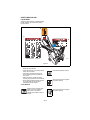
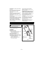
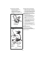
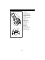
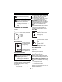
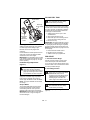
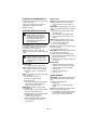
Sno-Thro®
Owner/Operator Manual
Models
938017 - SS522EC
938018 - SS722EC
U.S. Patents
5758436 and 5966846
ENGLISH
03392200 5/08
Printed in USA
TABLE OF CONTENTS
Safety . . . . . . . . . . . . . . . . . . . . . . . . . . . . . 4
Storage . . . . . . . . . . . . . . . . . . . . . . . . . . . 18
Assembly . . . . . . . . . . . . . . . . . . . . . . . . . . 8
Troubleshooting . . . . . . . . . . . . . . . . . . . 19
Controls & Features . . . . . . . . . . . . . . . . 10
Accessories . . . . . . . . . . . . . . . . . . . . . . . 19
Operation . . . . . . . . . . . . . . . . . . . . . . . . . 11
Service Parts . . . . . . . . . . . . . . . . . . . . . . 19
Maintenance Schedule . . . . . . . . . . . . . . 14
Specifications . . . . . . . . . . . . . . . . . . . . . 20
Service and Adjustments . . . . . . . . . . . . 15
Warranty. . . . . . . . . . . . . . . . . . . . . . . . . . 22
INTRODUCTION
NON-ENGLISH MANUALS
THE MANUAL
Manuals in languages other than English may
be obtained from your Dealer. Visit your
dealer or www.ariens.com for a list of
languages available for your equipment.
Manuals printed in languages other than
English are also available as a free download
on our website:
http://www.ariens.com
Before operation of unit, carefully and
completely read your manuals. If used
improperly, this unit could be dangerous and
cause personal injury or property damage.
The contents will provide you with safety
instructions for the safe use of your unit
during normal operation and maintenance.
All reference to left, right, front, or rear are
given from operator standing in operation
position and facing the direction of forward
travel.
MANUALES EN IDIOMAS
DIFERENTES DEL INGLES
Puede obtener manuales en idiomas
diferentes del inglés en su distribuidor. Visite
a su distribuidor o vaya a www.ariens.com
para obtener una lista de idiomas disponibles
para su equipo.
También puede imprimir manuales en
idiomas diferentes del inglés descargándolos
gratuitamente de nuestra página Web:
http://www.ariens.com
MODEL AND SERIAL NUMBERS
When ordering replacement parts or making
service inquiries, know the Model and Serial
numbers of your unit and engine.
Numbers are located on the product
registration form in the unit literature
package. They are printed on a serial number
label, located on the frame of your unit.
Serial
Number
Label
MANUELS NON ANGLAIS
Des manuels dans différentes langues sont
disponibles chez votre revendeur.
Rendez-vous chez votre revendeur ou allez
sur le site www.ariens.com pour consulter la
liste des langues disponibles pour votre
équipement.
Les manuels imprimés dans des langues
différentes de l'anglais sont également
disponibles en téléchargement gratuit sur
notre site Web :
http://www.ariens.com
GB - 2
Figure 1
OS0194
© Copyright 2008 Ariens Company
DELIVERY
• Record Unit Model and Serial numbers
here.
• Record Engine Model and Serial number
here.
PRODUCT REGISTRATION
The Ariens dealer must register the product
at the time of purchase. Registering the
product will help the company process
warranty claims or contact you with the latest
service information. All claims meeting
requirements during the limited warranty
period will be honored, whether or not the
product registration card is returned. Keep a
proof of purchase if you do not register your
unit.
Customer Note: If the dealer does not
register your product, please fill out, sign, and
return the product registration card to Ariens
or go to www.ariens.com.
Customer Note: If you have purchased this
product without complete assembly and
instruction by your retailer, it is your
responsibility to:
1. Read and understand all assembly
instructions in this manual. If you do not
understand or have difficulty following
the instructions, contact your nearest
Ariens Dealer for assistance. Make sure
all assembly has been properly
completed.
NOTE: To locate your nearest Ariens Dealer,
go to www.ariens.com on the internet.
UNAUTHORIZED REPLACEMENT
PARTS
Use only Ariens replacement parts. The
replacement of any part on this vehicle with
anything other than an Ariens authorized
replacement part may adversely affect the
performance, durability, or safety of this unit
and may void the warranty. Ariens disclaims
liability for any claims or damages, whether
warranty, property damage, personal injury or
death arising out of the use of unauthorized
replacement parts. To locate your nearest
Ariens Dealer, go to www.ariens.com on the
internet.
DISCLAIMER
Ariens reserves the right to discontinue,
make changes to, and add improvements
upon its products at any time without public
notice or obligation. The descriptions and
specifications contained in this manual were
in effect at printing. Equipment described
within this manual may be optional. Some
illustrations may not be applicable to your
unit.
GB - 3
WARNING: Improper assembly or
adjustments can cause serious injury.
2. Understand all Safety Precautions
provided in the manuals.
3. Review control functions and operation
of the unit. Do not operate the Sno-Thro
unless all controls function as described
in this manual.
4. Review recommended lubrication,
maintenance and adjustments.
5. Review Limited Warranty Policy.
6. Fill out a Product Registration Card and
return the card to the Ariens Company or
go to www.ariens.com.
SAFETY
PRACTICES AND LAWS
WARNING: To avoid injury to hands
and feet, always disengage clutches,
shut off engine, and wait for all
movement to stop before unclogging
or working on snow thrower.
Keep hands and feet away from
auger.
SAFETY ALERTS
Practice usual and customary safe working
precautions, for the benefit of yourself and
others. Understand and follow all safety
messages. Be alert to unsafe conditions and
the possibility of minor, moderate, or serious
injury or death. Learn applicable rules and
laws in your area. Always follow the practices
set forth in this manual.
REQUIRED OPERATOR
TRAINING
Look for these symbols to
point out important safety
precautions. They mean:
Original purchaser of this unit was instructed
by the seller on safe and proper operation. If
unit is to be used by someone other than
original purchaser; loaned, rented or sold,
ALWAYS provide this manual and any
needed safety training before operation.
Attention! Personal
Safety Is Involved!
Become Alert! Obey
The Message!
The safety alert symbols above and signal
words below are used on decals and in this
manual.
Read and understand all safety messages.
DANGER: IMMINENTLY
HAZARDOUS SITUATION! If not
avoided, WILL RESULT in death or
serious injury.
WARNING: POTENTIALLY
HAZARDOUS SITUATION! If not
avoided, COULD RESULT in death
or serious injury.
CAUTION: POTENTIALLY
HAZARDOUS SITUATION! If not
avoided, MAY RESULT in minor or
moderate injury. It may also be used
to alert against unsafe practices.
NOTATIONS
NOTE: General reference information for
proper operation and maintenance practices.
IMPORTANT: Specific procedures or
information required to prevent damage to
unit or attachment.
GB - 4
SAFETY DECALS AND
LOCATIONS
ALWAYS replace missing or damaged Safety
Decals. Refer to figure 2 below for Safety
Decal locations.
2
1
3
OS0157
Figure 2
3. DANGER!
1. DANGER!
• Read operator’s manual.
• Allow operation only by properly trained
adults, never children.
• Stop engine and remove ignition key
prior to leaving operator’s position for
any reason.
• Keep all controls, guards and safety
devices properly serviced and functional.
• Never direct discharge towards persons
or property that may be injured or
damaged by thrown objects.
Read Owner/Operator manual.
OL1801
Stop engine and remove ignition
key before clearing.
2. Hot Surface!
OL0900
OD0061
DO NOT touch unit parts which
might be hot from operation.
Allow parts to cool before
attempting to maintain, adjust or
service.
Stop engine and remove ignition
key before clearing.
OS1050
GB - 5
Stop engine, remove ignition
key, read manual before making
any repairs, adjustments.
OL4010
SAFETY RULES
Read, understand, and follow all safety
practices in Owner/Operator Manual before
beginning assembly or operating. Failure to
follow instructions could result in personal
injury and/or damage to unit.
ALWAYS remove key and/or wire from spark
plug before assembly, maintenance or
service. Unintentional engine start up can
cause death or serious injury.
Complete a walk around inspection of unit
and work area to understand:
• Work area • Your unit • All safety decals
ALWAYS check overhead and side
clearances carefully before operation.
ALWAYS be aware of traffic when operating
along streets or curbs.
Keep children and people away. Keep
children out of work area and under watchful
care of a responsible adult.
NEVER allow children to operate or play on
or near unit. Be alert and shut off unit if
children enter area.
DO NOT allow adults to operate unit without
proper training. Only trained adults may
operate unit. Training includes actual
operation.
Keep area of operation clear of all toys, pets,
and debris. Thrown objects can cause injury.
Check for weak spots on docks, ramps or
floors. Avoid uneven work areas and rough
terrain. Stay alert for hidden hazards.
DO NOT operate near drop-offs, ditches, or
embankments. Unit can suddenly turn over if
a wheel is over the edge of a cliff or ditch, or if
an edge caves in.
Falling snow, fog, etc. can reduce vision and
cause an accident. Operate unit only when
there is good visibility and light.
NEVER operate unit after or during the use of
medication, drugs or alcohol. Safe operation
requires your complete and unimpaired
attention at all times.
NEVER allow anyone to operate this unit
when their alertness or coordination is
impaired.
DO NOT operate unit without wearing
adequate winter outer garments. Wear
adequate safety gear, including safety
glasses with side shields, and protective
gloves. Wear proper footwear to improve
footing on slippery surfaces.
DO NOT wear loose clothing or jewelry and
tie back hair that may get caught in rotating
parts.
Protect eyes, face and head from objects that
may be thrown from unit. Wear appropriate
hearing protection.
Avoid sharp edges. Sharp edges can cut.
Moving parts can cut off fingers or a hand.
ALWAYS keep hands and feet away from all
rotating parts during operation. Rotating parts
can cut off body parts.
NEVER place your hands or any part of your
body or clothing inside or near any moving
part while unit is running.
ALWAYS keep hands away from all pinch
points.
DO NOT touch unit parts which might be hot
from operation. Allow parts to cool before
attempting to maintain, adjust or service.
Never direct discharge towards persons or
property that may be injured or damaged by
thrown objects. Use extreme caution on
gravel surfaces. Stay alert for hidden hazards
or traffic.
DO NOT use on gravel or crushed rock
surfaces.
DO NOT throw snow any higher than
necessary.
Deflected materials can cause injury and
property damage.
Always stand clear of the discharge area
when operating this unit.
Fumes from engine exhaust can cause injury
or death. DO NOT run engine in an enclosed
area. Always provide good ventilation.
ALWAYS disengage attachment, stop unit
and engine, remove key and allow moving
parts to stop before leaving operator’s
position.
ROTATING AUGER CAN CAUSE SERIOUS
INJURY. NEVER ATTEMPT TO UNCLOG
OR CLEAN UNIT WHILE ENGINE IS
RUNNING.
Read, understand, and follow all instructions
in the manual and on the machine before
starting.
GB - 6
Understand:
• How to operate all controls.
• The functions of all controls.
• How to STOP in an emergency.
Before starting engine, disengage control(s).
Use only approved extension cords and
receptacles when starting units equipped with
electric starter. DO NOT connect electric
starter cord to any wiring system that is not a
three-wire grounded system.
ALWAYS allow unit and engine to adjust to
outdoor temperatures before clearing snow.
Always be sure of your footing, especially
when operating in reverse or leaving the
operator’s position. Walk, never run during
operation.
DO NOT overload the machine capacity by
attempting to operate or to clear snow at too
fast a rate.
Slow down and turn corners slowly.
Do not operate in reverse unless absolutely
necessary. ALWAYS back up slowly. Always
look down and behind before and while
backing.
Disengage attachment drive when traveling
from one work area to another.
Abnormal Vibrations are a warning of trouble.
Striking a foreign object can damage unit.
Immediately stop unit and engine. Remove
key and wait for all moving parts to stop.
Remove wire from spark plug. Inspect unit
and make any necessary repairs before
restart.
Before cleaning, removing clogs or making
any inspections, repairs, etc.: disengage
clutch(es), stop unit and engine, remove key,
allow moving parts to stop. Allow hot parts to
cool.
Run unit a few minutes after clearing snow to
prevent freeze-up of attachment.
Disengage clutch bail when not in use. Before
starting engine: disengage clutch bail. DO
NOT use on gravel or crushed rock surfaces.
Check clutch and brake operation frequently.
Adjust and service as required. All motion of
auger must stop quickly when bail is
released.
Never leave a running unit unattended.
ALWAYS shut off engine before leaving unit.
ALWAYS remove key to prevent unauthorized
use.
Never carry passengers.
DO NOT operate on steep slopes. DO NOT
clear snow across the face of slopes. Keep all
movement on slopes slow and gradual. DO
NOT make sudden changes in speed or
direction. Use a slow speed to avoid stops or
shifts on slopes. Avoid starting or stopping on
a slope.
DO NOT park unit on a slope unless
absolutely necessary. When parking on a
slope always block the wheels.
ALWAYS shut off engine, remove key, and
drain fuel when transporting unit on a truck or
trailer.
Use extra care when loading or unloading
unit onto trailer or truck.
Secure unit chassis to transport vehicle.
NEVER secure from rods or linkages that
could be damaged.
DO NOT transport machine while engine is
running.
Keep unit free of ice or other debris. Clean up
oil or fuel spills.
This product is equipped with an internal
combustion type engine. DO NOT use unit on
or near any unimproved, forest-covered or
brush covered land unless exhaust system is
equipped with a spark arrester meeting
applicable local, state or federal laws. A spark
arrester, if it is used, must be maintained in
effective working order by operator.
Fuel is highly flammable and its vapors are
explosive. Handle with care. Use an
approved fuel container.
NO smoking, NO sparks, NO flames.
ALWAYS allow engine to cool before
servicing.
NEVER fill fuel tank when engine is running
or hot from operation.
NEVER fill or drain fuel tank indoors.
Replace fuel cap securely and clean up
spilled fuel.
Never fill containers inside a vehicle or on a
truck or trailer bed with a plastic liner. Always
place containers on the ground away from
your vehicle before filling.
When practical, remove gas-powered
equipment from the truck or trailer and refuel
it on the ground. If this is not possible, then
refuel such equipment on a trailer with a
portable container, rather than from a
gasoline dispenser nozzle.
Keep the nozzle in contact with the rim of the
fuel tank or container opening at all times until
fueling is complete. Do not use a nozzle
lock-open device.
GB - 7
If fuel is spilled on clothing, change clothing
immediately.
Before tipping unit up onto housing, remove
fuel so no spills will occur. Ensure unit is
secure and will not tip over during
maintenance.
ALWAYS keep protective structures, guards,
and panels in good repair, in place and
securely fastened. NEVER modify or remove
safety devices.
DO NOT change engine governor settings or
over-speed engine.
Fumes from engine exhaust can cause injury
or death. DO NOT run engine in an enclosed
area. Always provide good ventilation.
ALWAYS maintain unit in safe operating
condition. Damaged or worn out muffler can
cause fire or explosion.
Keep all hardware properly tightened.
Maintain or replace safety and instruction
labels, as necessary.
NEVER store unit with fuel in fuel tank, inside
a building where any ignition sources are
present such as hot water heaters, space
heaters, or clothes dryers. Allow the engine to
cool before storing in any enclosure.
Drain fuel and allow engine to cool
completely before storing in closed area or
covering unit.
For extended storage, clean unit thoroughly.
See Engine Manual for proper storage.
Use only attachments or accessories
designed for your unit.
Check components frequently. If worn or
damaged, replace with manufacturer’s
recommended parts.
ASSEMBLY
WARNING: AVOID INJURY. Read
and understand the entire Safety
section before proceeding.
3
TOOLS REQUIRED
4
7/16" Open-end wrench, Pliers
5
ASSEMBLY
Handlebar Assembly
1. Remove wing knobs and release J-bolts
from lower handlebar (figure 3).
2. Unfold upper handlebar.
NOTE: Adjust handlebar to a height
comfortable for the operator (see Handlebar
Height Adjustment on page 12).
3. Put J-bolts through the upper handlebar
and lower handlebar holes.
4. Replace and tighten wing knobs to
secure upper handlebar.
2
1
6
1. Lower Handle
Bar
2. Upper Handle
Bar
3. Auger Clutch
Bail
4. Knob
5. J-Bolt
6. J-Bolt Holes
Figure 3
GB - 8
DS0072
Discharge Chute Assembly
Discharge Chute Crank Assembly
1. Remove bolt and nut from rear of
discharge chute (figure 4).
2. Tip discharge chute up and install
hardware just removed. Tighten
hardware at rear of discharge chute first,
then sides.
3
2
1
4
1. Discharge Chute
2. Rear Bolt and Nut
3. Chute Handle
4. Side Hardware
1. Remove nut from bolt that holds recoil
starter handle bracket in place (figure 5).
2. Pull the chute crank assembly up so hole
in chute crank bracket fits behind/under
lower handle bar and over bolt end.
NOTE: DO NOT pull chute crank bracket past
the lower handle bar or the 48T gear and
spacer will fall off into unit.
3. With crank knob straight up and
discharge chute straight forward, check
that 48T gear meshes with 12T pinion.
Align space and tooth identification
marks.
4. Insert cotter pin (taped to chute crank
assembly) through 48T gear and chute
crank shaft. Slight movement of the
crank shaft or discharge chute may be
needed to align holes.
5. Rotate chute crank to access cotter pin.
Secure pin by bending ends over.
6. Secure chute crank and starter handle to
lower handle bar by reinstalling nut from
step 1.
Fill Engine Fuel Tank
Figure 4
OS1520
See Filling Fuel Tank on page 12.
Check Function of all Controls
1
Ensure unit runs and performs properly (see
Operation on page 11).
2
8
3
4
7
5
6
1. Chute Crank
2. Identification
Marks
3. 12T Pinion
4. Spacer
5. 48T Gear
6. Cotter Pin
7. Nut
8. Recoil Starter
Handle Bracket
Figure 5
IS0212
GB - 9
CONTROLS & FEATURES
2
1
3
4
5
6
22
7
8
9
21
20
19
10
18
17
11
16
15
1.
2.
3.
4.
5.
6.
7.
8.
9.
10.
11.
12.
13.
14.
15.
16.
17.
18.
19.
20.
21.
22.
12
14
13
Figure 6
GB - 10
Auger Clutch Bail
Handlebar
Discharge Chute Crank
Handlebar Wing Knob
Spark Plug Access Cover
Discharge Chute Handle
Exhaust
Discharge Chute Deflector
Auger Housing
Auger
Ignition Switch
Fuel Level Indicator
Starter Button
Choke Control Knob
Power Cord
Primer Bulb
Scraper Blade
Cowl
Discharge Chute
Chute Deflector Handle
Fuel Tank and Cap
Recoil Starter Handle
OPERATION
WARNING: AVOID INJURY. Read
and understand the entire Safety
section before proceeding.
WARNING: To avoid injury to hands
and feet, always disengage clutches,
shut off engine, and wait for all
movement to stop before unclogging
or working on snow thrower.
Keep hands and feet away from
auger.
CONTROLS AND FEATURES
See figure 6 for controls and features
locations.
2. Pull recoil starter handle. Auger should
rotate with the turning of the engine.
3. Release the auger clutch bail.
4. Pull recoil starter handle again. Auger
must not rotate as engine turns.
IMPORTANT: If belt squeals when auger
clutch bail is engaged, auger may be frozen.
Immediately release auger clutch bail and
move the unit to a heated area to thaw.
Auger
When handlebar is lifted so auger contacts
the ground, auger propels unit forward while
throwing snow. Forward speed will vary
according to depth and moisture content.
Primer Bulb
Ignition Switch
1
STOP
RUN
Pushing the primer bulb in
adds fuel for easier engine
start (see Starting and Shutting
off on page 13).
Ignition switch is operated by
a removable key that has two
positions.
1. STOP
2. RUN
2
OS1620
Choke Control Knob
OS1680
Pulled out (closed) – chokes
off air to the engine for easier
start.
Pushed in (open) - allows for
normal operation.
Auger Clutch Bail
Squeeze auger clutch
bail against handlebar
to engage auger.
Engaged
Disengaged
OS1570
IMPORTANT: Gradually push in choke
control knob after engine starts.
Recoil Starter Handle
Release auger clutch
bail to disengage and
brake auger.
Check Auger Clutch Bail
When pulled, recoil starter handle will turn
engine over.
IMPORTANT: DO NOT let recoil starter
handle snap back against unit.
Discharge Chute (Figure 7)
WARNING: Check auger clutch
before each use. Auger brake MUST
DISENGAGE when clutch is
engaged. Auger brake MUST STOP
AUGER WITHIN 5 SECONDS of
releasing auger clutch bail.
IMPORTANT: If auger clutch bail moves
freely with no resistance before contacting
handlebar or does not operate as indicated in
the following steps, adjust or repair unit
before operating (see Drive Belt Adjustment
on page 16).
1. With key in STOP position, engage
auger clutch bail.
Discharge chute rotates 220°.
ALWAYS position discharge chute in safe
direction and angle, away from operator and
bystanders, before starting engine.
Rotating Discharge Chute (Figure 7)
Two options are available to rotate discharge
chute:
• Discharge Chute Crank
• Discharge Chute Handle
IMPORTANT: DO NOT force a frozen
discharge chute. Start engine and run for 3-5
minutes to thaw. If still frozen, take to a warm
place until controls are free.
GB - 11
FILLING FUEL TANK
Discharge
Chute Crank
WARNING: AVOID INJURY. Read
and understand the entire Safety
section before proceeding.
Discharge
Chute Handle
Handlebar
Height
Adjustment
Holes
OS2060
Figure 7
Discharge Chute Deflector
ALWAYS position discharge chute deflector
at a safe angle before starting engine.
DO NOT throw snow any higher than
necessary.
Pull chute deflector handle upward to throw
snow lower. Push chute deflector handle
downward to throw snow higher.
IMPORTANT: If chute deflector does not stay
in set position, adjust (see Discharge Chute
Deflector Adjustment on page 16), or repair
before operating.
Handlebar Height Adjustment
(Figure 7)
CAUTION: Adjust auger control
cable after changing handlebar
height (see Drive Belt Adjustment on
page 16). Route auger control cable
over handlebar as shown in figure 7.
Adjust handlebar height by selecting the
appropriate handlebar height adjustment
holes. Tighten handlebar wing knobs to
secure upper handlebar to lower handlebar.
NOTE: The upper handlebar can be folded
for storage.
IMPORTANT: Two cycle engines require that
oil be mixed with fuel. Failure to mix oil with
fuel will result in seizure and severe damage
to engine. DO NOT use gasohol or gasoline
containing alcohol. See Engine Manual for
correct type of fuel/oil mixture.
1. ALWAYS place unit in open or wellventilated area.
2. Stop engine and allow to cool.
3. Clean fuel cap and surrounding area to
prevent dirt from entering fuel tank.
4. Remove fuel cap.
IMPORTANT: See Engine Manual for proper
fuel/oil mixture. Fuel/oil mixture left standing
for prolonged periods will begin to separate;
thoroughly shake fuel/oil mixture before use.
NOTE: See Specifications on page 20 for fuel
tank capacity.
5. Fill fuel tank with fuel/oil mixture.
6. Replace fuel cap and tighten.
7. ALWAYs clean up any spilled fuel.
PRE-START
1. Check for Frozen Auger
With key in STOP position, engage auger
clutch bail and pull recoil starter handle.
If you cannot pull recoil starter handle, auger
is frozen. Move unit to a heated area to thaw
to prevent possible damage.
2. Check Auger Clutch
WARNING: Check auger clutch
before each use. Auger brake MUST
DISENGAGE when clutch is
engaged. Auger brake MUST STOP
AUGER WITHIN 5 SECONDS of
releasing auger clutch bail. See
Check Auger Clutch Bail on page 11.
3. Check Engine Fuel Level
Scraper Blade
The scraper blade allows the back of the
housing to keep better contact with the
surface being cleared. It also prevents
damage to the housing from normal wear.
IMPORTANT: DO NOT allow scraper blade to
wear down too far or auger housing will
become damaged.
WARNING: AVOID INJURY. Read
and understand the entire Safety
section before proceeding.
Add fuel if required (see Filling Fuel Tank on
page 12).
GB - 12
STOPPING IN AN EMERGENCY
Electric Start
Immediately release auger clutch bail to stop
unit in an emergency.
Stop engine, remove key and wait for all
rotating parts to stop before leaving
operator’s position.
NOTE: Electric start models can be started
manually (see Manual Start on page 13).
1. Connect extension cord to prongs on
starter.
IMPORTANT: Prevent damage to unit. Know
voltage of your starter and only use matching
outlets.
2. Plug extension cord into 120V 3-wire,
grounded outlet.
3. Turn discharge chute straight ahead.
4. Push primer bulb 1 to 3 times for cold
engine.
NOTE: When temperature is below -15° F
(-26° C) additional priming may be needed.
5. Insert key into ignition switch.
6. Turn key to RUN position.
NOTE: A warm engine requires less choking
than a cold engine.
7. Pull choke control knob out.
IMPORTANT: DO NOT crank engine for more
than 5 seconds on each attempt.
8. Push starter button until engine starts.
9. Open choke slowly by gradually pushing
choke control knob in.
10. Disconnect power cord from outlet, then
from starter.
STARTING AND SHUTTING OFF
WARNING: FAILURE TO FOLLOW
INSTRUCTIONS could result in
personal injury and/or damage to
unit. DO NOT attempt to start your
unit at this time. Read entire
Owner/Operator Manual and the
Engine Manual first.
IMPORTANT: Allow unit and engine to adjust
to the outdoor temperature before clearing
snow. Before shutting unit off, run auger a
few minutes to prevent freeze-up.
NOTE: Try out each control without the
engine running to see how it works and what
it does.
WARNING: THROWN OBJECTS
could cause death or serious injury.
ALWAYS position discharge chute
straight ahead (away from operator)
for starting.
Shutting Off
Manual Start
1. Turn discharge chute straight ahead.
NOTE: When temperature is below -15° F
(-26° C) additional priming may be needed.
2. Push primer bulb 1 to 3 times for cold
engine.
NOTE: A warm engine requires less choking
than a cold engine.
3. Pull choke control knob out.
4. Insert key into ignition switch.
5. Turn key to RUN.
6. Stand behind unit. Grasp starter handle
and pull rope out slowly until it pulls
harder, let rope rewind slowly.
IMPORTANT: DO NOT let starter handle
snap against unit.
7. Pull rope with a rapid continuous full arm
stroke. Let rope rewind slowly.
8. Repeat steps 6 and 7 until engine starts.
(If engine does not start, see
Troubleshooting on page 19.)
9. When engine has started, open choke
slowly by gradually pushing choke
control knob in.
1. Engage and run auger a few minutes
after use to prevent freeze-up of auger.
2. Release auger clutch bail and allow
auger to stop.
3. Turn key to STOP position.
4. Remove key.
SNOW REMOVAL
IMPORTANT: Allow unit and engine to adjust
to the outdoor temperature before clearing
snow.
To propel unit and throw snow:
1. Start engine.
2. Engage auger clutch bail to engage
auger.
NOTE: Do not lift handlebar so high to allow
snow to kick back from under unit.
3. Lift handlebar so auger contacts surface
to be cleared. Lift the handlebar only
high enough to propel unit forward.
GB - 13
Tips for Operation
Snow is best removed as soon as possible
after a snow fall.
To clear an area, run unit in an overlapping
series of paths. For large areas, start in the
middle and throw snow to each side, so snow
is not cleared more than once.
ALWAYS direct snow away from area to be
cleared and with direction of the wind.
IMPORTANT: DO NOT overload unit capacity
by attempting to clear snow at too fast a rate.
TRAVELING TO ANOTHER WORK
AREA
1. Release auger clutch bail to disengage
auger.
2. Press down on handlebar enough to
raise front of unit slightly off the ground
and push or pull unit.
TRANSPORT
ALWAYS shut off engine and drain fuel when
transporting unit on a truck or trailer.
Use extra care when loading or unloading
unit onto trailer or truck.
Secure unit chassis to transport vehicle.
NEVER secure by rods or linkages that could
be damaged.
DO NOT transport machine while engine is
running.
MAINTENANCE SCHEDULE
WARNING: AVOID INJURY. Read
and understand the entire Safety
section before proceeding.
Interval
Task
Yearly
Action
Check Auger
Clutch
WARNING: Check auger clutch before each
use. Auger brake MUST DISENGAGE when
clutch is engaged. Auger brake MUST
STOP AUGER WITHIN 5 SECONDS of releasing
auger clutch bail (see Check Auger Clutch Bail on
page 11).
Clean Unit
After each use, brush snow and debris off with a soft
bristled brush. Occasionally apply a light coat of
spray lubricant to exposed metal joints and surfaces.
Wipe off excess with soft cloth. Do not use abrasives
or harsh cleaners.
Follow Engine
Manual
Maintenance
Schedule
Perform scheduled engine maintenance. See
Engine Manual for detailed instructions.
Each Use
Every 10 Hours
Ariens Dealers will provide any service or
adjustments which may be required to keep
your unit operating at peak efficiency. Should
engine service be required, contact an Ariens
dealer or an authorized engine
manufacturer's service center.
Check Fasteners
Make sure all hardware is tightened properly.
Check Drive Belt
Adjustment
See Drive Belt Adjustment on page 16.
Check Scraper
Blade
Check scraper blade for wear. DO NOT allow
scraper blade to wear down too far or auger housing
will become damaged.
GB - 14
SERVICE AND ADJUSTMENTS
3. Remove auger drive pulley.
4. Remove old belt.
WARNING: AVOID INJURY. Read
and understand the entire Safety
section before proceeding.
Install (Figure 8)
SERVICE POSITION
1.
2.
3.
4.
Install new belt on drive pulley and idlers.
Install drive belt on auger drive pulley.
Install auger drive pulley on unit.
Connect extension spring to idler
arm/brake.
5. Adjust drive belt (see Drive Belt
Adjustment on page 16).
6. Install cowl.
Place unit on a flat level surface.
DRIVE BELT REPLACEMENT
Remove (Figure 8)
1. Remove cowl.
2. Disconnect extension spring on idler
arm/brake.
1
2
1. Extension Spring
2. Idler Arm/Brake
3. Idler
4. Drive Pulley
5. Drive Belt
6. Auger Drive
Pulley
3
4
5
6
Figure 8
OS4001
DISCHARGE CHUTE
ADJUSTMENT
If discharge chute rotates while throwing
snow, tighten four screws holding discharge
chute to housing to 11 – 12 lbf-in
(1.23 – 1.35 N•m).
IMPORTANT: DO NOT overtighten screws.
1. Remove nut and bolt from rear of
discharge chute.
2. Tip discharge chute forward.
3. Tighten two rear screws.
4. Tighten two front screws.
5. Reposition discharge chute and fasten
with nut and bolt.
2
1
3
4
1. Rear Screw
2. Rear Nut and
Bolt
3. Discharge Chute
4. Front Screw
Figure 9
GB - 15
DISCHARGE CHUTE DEFLECTOR
ADJUSTMENT
If discharge chute deflector does not stay in
position while throwing snow, adjust chute by
tightening fasteners (figure 10).
Fasteners
Figure 10
Measure Bail Spring Length With
Auger Clutch Bail Disengaged
OS0181
DRIVE BELT ADJUSTMENT
WARNING: Improper adjustment
could result in death or serious injury.
Auger brake MUST DISENGAGE
when clutch is engaged. Auger brake
MUST STOP AUGER WITHIN 5
SECONDS of releasing auger clutch
bail.
Adjust Auger Control Cable
(Figure 11)
1. Measure bail spring length with auger
clutch bail DISENGAGED.
2. Engage auger clutch bail.
3. Measure bail spring length with auger
clutch bail ENGAGED.
4. The difference in bail spring length
measurements should be 9/16 – 5/8 in.
(14.3 – 15.9 mm).
• If bail spring length IS within
specifications, go to Adjust Belt Finger.
• If bail spring length IS NOT within
specifications, go to Adjust Cable.
Measure Bail Spring Length With
Auger Clutch Bail Engaged
OS3500
Figure 11
Adjust Cable
IMPORTANT: After adjustment, if the auger
control cable is taut when the auger clutch
bail is disengaged, the auger brake will not
work properly. If this condition occurs, replace
the belt and restart the drive belt adjustment
procedure.
1. Loosen jam nut on auger control cable
adjuster.
2. Turn adjustment barrel to lengthen or
shorten the cable as needed to achieve
spring extension defined in step 4 of
Adjust Auger Control Cable (Figure 11).
3. Tighten jam nut on auger control cable
adjuster.
Adjust Belt Finger (Figure 12)
1. Remove cowl.
IMPORTANT: Auger clutch bail MUST be
engaged while performing steps 2 through 5.
2. Engage auger clutch bail.
GB - 16
3. Loosen belt finger and rotate until there
is 1/32 – 1/16 in. (0.8 – 1.6 mm) gap
between belt finger and drive belt.
4. Tighten belt finger.
5. Recheck gap between belt finger and
drive belt. Adjust belt finger until there is
1/32 – 1/16 in. (0.8 – 1.6 mm) gap
between belt finger and drive belt.
6. Go to Check Auger Stopping Time next.
Check Auger Stopping Time
WARNING: Improper adjustment
could result in death or serious injury.
Auger brake MUST DISENGAGE
when clutch is engaged. Auger brake
MUST STOP AUGER WITHIN 5
SECONDS of releasing auger clutch
bail.
WARNING: Auger MUST NOT rotate
when the auger clutch bail is
disengaged.
1. Start unit.
2. Engage auger clutch bail for 5 seconds.
IMPORTANT: Auger MUST STOP within 5
seconds of disengaging auger clutch bail.
3. Disengage auger clutch bail.
• If auger stops within 5 seconds, the
adjustment is complete.
• If auger does not stop within 5 seconds,
repeat the entire procedure in Drive Belt
Adjustment on page 16.
IMPORTANT: Replace the drive belt if the
Drive Belt Adjustment procedure has been
completed twice and the drive belt is still not
adjusted properly.
4. Replace cowl.
WARNING: ROTATING PARTS can
cut off body parts. Keep hands and
feet away. Loose clothing, long hair
or scarves can get caught in rotating
parts and cause death or serious
injury.
1
2
3
1. Idler
2. Idler Nut
3. Belt Finger
4. Drive Belt
1/32 – 1/16 in.
(0.8 – 1.6 mm)
3
4
4
Figure 12
GB - 17
OS4501
STORAGE
FUEL SYSTEM
WARNING: AVOID INJURY. Read
and understand the entire Safety
section before proceeding.
SHORT TERM
IMPORTANT: NEVER spray unit with high
pressure water or store unit outdoors.
Run with attachment clutch engaged a few
minutes after each use to free unit of any
loose or melting snow.
Inspect unit for visible signs of wear,
breakage or damage.
Keep all nuts, bolts and screws properly
tightened and know unit is in safe working
condition.
Store unit in a cool, dry protected area.
LONG TERM
Clean unit thoroughly with mild soap and low
pressure water and lubricate (see
Maintenance). Touch up all scratched painted
surfaces.
Gasoline left in the fuel system for extended
periods without a stabilizer will deteriorate,
resulting in gum deposits in the system.
These deposits can damage the carburetor
and the fuel hoses, filter and tank. Prevent
deposits from forming in the fuel system
during storage by adding a quality fuel
stabilizer to the fuel. Follow the
recommended mix ratio found on the fuel
stabilizer container.
To treat the fuel system for storage:
1. Add fuel stabilizer (Ariens p/n 00592900)
according to manufacturer’s instructions.
2. Run engine for at least 10 minutes after
adding stabilizer to allow it to reach the
carburetor.
NEVER store the engine with fuel in the fuel
tank inside of a building with potential
sources of ignition.
GB - 18
TROUBLESHOOTING
PROBLEM
Engine will
not
crank/start
PROBABLE CAUSE
CORRECTION
1. Key not in RUN position.
2. Fuel tank empty.
3. Clogged fuel filter.
1. Turn key to RUN position.
2. Fill fuel tank.
3. Replace fuel filter. See Engine
Manual.
4. Contact your Ariens Dealer.
4. Faulty electric starter or wire
connections.
Engine
stops
1. Out of fuel.
2. Improperly mixed or contaminated
fuel.
3. Faulty spark plug.
4. Clogged fuel filter.
1. Fill fuel tank (see Filling Fuel Tank
on page 12).
2. Drain fuel tank and refill with new
fuel/oil mixture (see Filling Fuel
Tank on page 12).
3. Replace spark plug. See Engine
Manual.
4. Replace fuel filter. See Engine
Manual.
Discharge
chute will
not turn
1. Discharge chute gears are frozen.
1. Move unit to a warm area to thaw.
Auger will
not turn or
throw snow
1. Auger is frozen.
2. Ice or debris is obstructing auger.
1. Move unit to a warm area to thaw.
2. With engine off, and auger
disengaged, remove obstructions.
3. Adjust drive belt (see Drive Belt
Adjustment on page 16).
4. Adjust drive belt. See (see Drive
Belt Adjustment on page 16).
3. Auger control cable out of
adjustment.
4. Drive belt slipping.
ACCESSORIES
SERVICE PARTS
See your authorized Ariens dealer to add
the additional accessories available to your
Sno-Thro.
73800300
Discharge Chute Crank Kit
73800100
Electric Starter Kit
Order the following parts through your
Dealer:
Part no.
Qty
Description
07236300
1
Drive Belt
03813800
1
Scraper Blade
02910800
1
Fuel Filter
00592900
1
Fuel Stabilizer
GB - 19
SPECIFICATIONS
Model Number
938017
938018
Description
SS522EC
SS722EC
Engine - Tecumseh (Two-Cycle)
TH139SA
TH139SP
5 (3.73)
7 (5.22)
Engine Power – hp (kW) at Maximum RPM
3950 ± 150
-1
Fast Idle Speed – RPM (min )
Displacement – in. (cc)
8.46 (139)
Fuel
See Engine Manual.
Fuel to Oil Mix
50:1
Fuel Tank Capacity – qt. (L)
1.2 (1.1)
Electric Start
120V
Snow Clearing Width – in. (cm)
22 (56)
Chute
Chute Rotation Angle
220°
Discharge Chute Crank
Yes
Discharge Chute Handle
Yes
Auger
Speed – RPM
1430
Diameter – in. (cm)
9.0 (23)
Drive
Auger Drive
Yes
Drive Belt
3L Section, Single “V” Construction,
Raw Edge Kevlar Cord
Size and Weight
Height – in. (cm)
40.8 (104)
Length – in. (cm)
43.2 (110)
Width – in. (cm)
22 (56)
Weight – lbs (Kg)
80 (36.3)
GB - 20
Three-Year Limited Sno-Thro®
Warranty
Ariens Company (Ariens) warrants to the original purchaser that Ariens Sno-Thro products will be free from
defects in material and workmanship for a period of three years after the date of purchase. An authorized
Ariens dealer will repair any defect in material or workmanship, and repair or replace any defective part,
subject to the conditions, limitations and exclusions set forth herein. Such repair or replacement will be free of
charge to the original purchaser (labor and parts), except as noted below.
The duration of this warranty applies only if the product is put to personal use around a household or
residence. If the product is put to any business use, agricultural, commercial, or industrial, then the duration
of this warranty shall be 90 days after the date of purchase, or one year after the date of purchase if the
product is labeled as a Pro, Professional, or Commercial Product. If any product is rented or leased, then the
duration of this warranty shall be 90 days after the date of purchase. It is the owner’s responsibility to perform
correctly the maintenance and minor adjustments explained in the owner’s manual.
®
Dura-Clean Auger Limited Lifetime Warranty
Ariens warrants to the original purchaser that the rubber components of the DURA- CLEAN Auger on
single stage Sno-Thro models manufactured by Ariens and sold after July 1, 1999 will be free from
defects in material and workmanship for the life of the unit.
The lifetime limited warranty on the rubber components of the DURA-CLEAN Auger applies only if the
product is put to personal use around a household or residence. If the product is put to any business
use, agricultural, commercial, or industrial, then the duration of this warranty shall be 90 days after the
date of purchase. An authorized Ariens dealer will replace any rubber component of the DURA-CLEAN
Auger found upon examination by Ariens to be defective or worn beyond the wear indicator. Replacements will be supplied free of charge. Labor is not included after two years from the date of purchase of
the Sno-Thro unit (all repairs must be completed by an authorized Ariens dealer).
Service Parts and Accessories Warranty
•
Genuine Ariens or Gravely brand service parts and accessories are warranted to be free from defects
in material and workmanship for a period of 90 days after the date of purchase. An authorized Ariens
dealer will repair or replace any such part or accessory free of charge, except for labor, during that
period.
Exceptions, Limitations, Exclusions
Customer Responsibilities
Register the product immediately at the time of sale. If the dealer does not register the product, the
customer must complete the product registration card in the literature package and return it to the Ariens
Company, or register the unit online at www.ariens.com or www.gravely.com.
To obtain warranty service, the original purchaser must:
• Perform the maintenance and minor adjustments explained in the owner’s manual.
• Promptly notify Ariens or an authorized Ariens or Gravely service representative of the need for
warranty service.
• Transport the product to and from the place of warranty service.
• Have the warranty service performed by an authorized Ariens or Gravely service representative.
To find an Ariens or Gravely authorized service representative, contact Ariens at:
655 W. Ryan Street
Brillion, WI 54110
(920) 756 - 2141
www.ariens.com
www.gravely.com
Snow_2008
GRAVELY® | STENS® | LOCKE® | NATIONAL® MOWER | BYNORM® | EVERRIDE® | GREAT DANE® 22
ARIENS COMPANY
Limitations
•
•
Batteries are warranted only for a period of 12 months after date of purchase, on a prorated basis. For
the first 90 days of the warranty period, a defective battery will be replaced free of charge. If the
applicable warranty period is more than 90 days, Ariens will cover the prorated cost of any defective
battery, for up to 12 months after the date of purchase.
Friction discs, belts, idlers, cables, and electrical components on Sno-Thro models put to personal use
around a household or residence are warranted against defects in materials or workmanship to the
original purchaser for two years.
Exclusions – Items Not Covered by This Warranty
•
•
•
•
•
•
Engines and engine accessories are covered only by the engine manufacturer’s warranty and are not
covered by this warranty.
Parts that are not genuine Ariens or Gravely service parts are not covered by this warranty.
Damages resulting from the installation or use of any part, accessory or attachment which is not
approved by the Ariens Company for use with product(s) identified herein are not covered by this
warranty.
The following maintenance, service and replacement items are not covered by this warranty unless
they are noted in the Limitations section above: lubricants, spark plugs, oil, oil filters, air filters, shoes,
runners, scraper blades, shear bolts, headlights, light bulbs.
Any misuse, alteration, improper assembly, improper adjustment, neglect, or accident which requires
repair is not covered by this warranty.
This warranty applies only to products purchased in the United States (including Puerto Rico) and
Canada. In all other countries, contact place of purchase for warranty information.
Disclaimer
Ariens may from time to time change the design of its products. Nothing contained in this warranty shall be
construed as obligating Ariens to incorporate such design changes into previously manufactured products,
nor shall such changes be construed as an admission that previous designs were defective.
LIMITATION OF REMEDY AND DAMAGES
Ariens Company’s liability under this warranty, and under any implied warranty that may exist, is limited to
repair of any defect in workmanship, and repair or replacement of any defective part. Ariens shall not be
liable for incidental, special, or consequential damages (including lost profits). Some states do not allow the
exclusion of incidental or consequential damages, so the above limitation or exclusion may not apply to you.
DISCLAIMER OF FURTHER WARRANTY
Ariens Company makes no warranty, express or implied, other than what is expressly made in this
warranty. If the law of your state provides that an implied warranty of merchantability, or an implied
warranty of fitness for particular purpose, or any other implied warranty, applies to Ariens Company,
then any such implied warranty is limited to the duration of this warranty. Some states do not allow
limitations on how long an implied warranty lasts, so the above limitation may not apply to you.
This warranty gives you specific legal rights, and you may also have other rights which
vary from state to state.
ARIENS COMPANY
GRAVELY® | STENS® | LOCKE® | NATIONAL® | BYNORM® | EVERRIDE® | GREAT DANE®
Snow_2008
23
Ariens Company
655 West Ryan Street
Brillion, WI 54110-1072
920-756-2141
Fax 920-756-2407
www.ariens.com