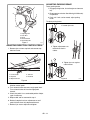
1
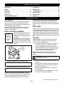
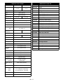
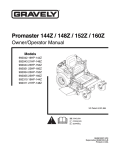
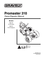
Promaster 310
Owner/Operator Manual
Models
990018
25 HP Kohler
990020
23 HP Kawasaki
ENGLISH
FRANÇAIS
ESPAÑOL
08495100A 1/02
Supercedes 08495100
Printed in USA
CONTROLS AND FEATURES
ENGLISH
1. Parking Brake Lever
2. Throttle Lever
3. Choke Control
4. Oil Pressure Warning Light
5. Deck Lift Lever
6. Cut Height Lever
7. Ignition Switch
8. PTO Switch
9. Handlebar
10. Hydraulic Oil Cooler
11. Muffler
12. Hydraulic Pump
13. Transmission Bypass Valve
14. Hydraulic Reservoir Fill
15. Battery
16. Direction Control Pedal
17. Fuel Tank Cap
18. Seat Suspension Adjustment Knob
19. Seat Adjustment Lever
20. Hourmeter
FRANÇAIS
1. Levier de frein de stationnement
2. Manette des gaz
3. Starter
4. Voyant de pression d’huile
5. Levier de relevage du carter de
coupe
6. Levier de hauteur de coupe
7. Contacteur d’allumage
8. Commande de la PdF
9. Guidon
10. Refroidisseur d’huile hydraulique
11. Silencieux
12. Pompe hydraulique
13. Distributeur de dérivation de la
transmission
14. Remplissage du réservoir d’huile
hydraulique
15. Batterie
16. Pédale de commande de direction
17. Bouchon du réservoir de carburant
18. Molette de réglage de la suspension
du siège
19. Levier de réglage du siège
20. Compteur horaire
WARNING
The engine exhaust from this product
contains chemicals known to the State
of California to cause cancer, birth
defects or other reproductive harm.
2
ESPAÑOL
1. Palanca del freno de estacionamiento
2. Palanca del acelerador
3. Control del estrangulador
4. Luz de advertencia de la presión
del aceite
5. Palanca de elevación de la
plataforma
6. Palanca de la altura de corte
7. Interruptor de encendido
8. Interruptor de la TDF
9. Manillar
10. Refrigerador del aceite hidráulico
11. Escape
12. Bomba hidráulica
13. Válvula de desviación de la
transmisión
14. Llenado del depósito hidráulico
15. Batería
16. Pedal de control de la dirección
17. Tapón del depósito del combustible
18. Perilla de ajuste de la suspensión
del asiento
19. Palanca de ajuste del asiento
20. Horómetro
TABLE OF CONTENTS
Controls and Features . . . . . . . . . . . . . . . . . . . . . . . . 2
Introduction . . . . . . . . . . . . . . . . . . . . . . . . . . . . . . . . . 3
Safety . . . . . . . . . . . . . . . . . . . . . . . . . . . . . . . . . . . . . . 4
Assembly . . . . . . . . . . . . . . . . . . . . . . . . . . . . . . . . . . . 8
Operation . . . . . . . . . . . . . . . . . . . . . . . . . . . . . . . . . . . 8
Maintenance. . . . . . . . . . . . . . . . . . . . . . . . . . . . . . . . 11
Service and Adjustments . . . . . . . . . . . . . . . . . . . . . 13
Storage . . . . . . . . . . . . . . . . . . . . . . . . . . . . . . . . . . . . 16
Accessories . . . . . . . . . . . . . . . . . . . . . . . . . . . . . . . . 16
Attachments . . . . . . . . . . . . . . . . . . . . . . . . . . . . . . . . 16
Troubleshooting . . . . . . . . . . . . . . . . . . . . . . . . . . . . . 16
Specifications. . . . . . . . . . . . . . . . . . . . . . . . . . . . . . . 17
Service Parts . . . . . . . . . . . . . . . . . . . . . . . . . . . . . . . 17
Warranty . . . . . . . . . . . . . . . . . . . . . . . . . . . . . . . . . . . 18
INTRODUCTION
THE MANUAL
affect the performance, durability, or safety of this unit.
Gravely disclaims liability for any claims or damages,
whether warranty, property damage, personal injury or
death arising out of the use of unauthorized replacement
parts.
Before operation of unit, carefully and completely read
your manuals. The contents will provide you with an
understanding of safety instructions and controls during
normal operation and maintenance.
All reference to left, right, front, or rear are given from
operator sitting in operation position and facing the
direction of forward travel.
DISCLAIMER
MODEL AND SERIAL NUMBERS
Transfer
model & serial
number label
from product
registration
here.
When ordering replacement parts or
making service inquiries, know the
Model and Serial numbers of your unit
and engine.
Numbers are located on the product
registration form in the unit literature
package. They are printed on a serial
number label, located on the frame of
your unit.
Serial
Number
Label
Figure 2
Gravely reserves the right to discontinue, make changes
to, and add improvements upon its products at any time
without public notice or obligation. The descriptions and
specifications contained in this manual were in effect at
printing. Equipment described within this manual may be
optional. Some illustrations may not be applicable to your
unit.
DELIVERY
Customer Note: If you have purchased this product
without complete assembly and instruction by your
retailer, it is your responsibility to:
1. Read and understand all assembly instructions in
this manual. If you do not understand or have
difficulty following the instructions, contact your
nearest Gravely Dealer for assistance. Make sure
all assembly has been properly completed and
safety interlock system works properly.
NOTE: To locate your nearest Gravely Dealer, call
1-800-472-8359 or go to www.gravely.com on the
internet.
WARNING: Improper assembly or adjustments
can cause serious injury.
OF3380
•
Record Unit Model and Serial numbers here.
•
Record Engine Model and Serial numbers here.
2. Understand all Safety Precautions provided in the
manuals.
3. Review control functions and operation of the unit.
Do not operate unit unless all controls function as
described in this manual.
4. Review recommended lubrication, maintenance
and adjustments.
5. Fill out Original Purchaser Registration Card and
return the card to Gravely Company.
UNAUTHORIZED REPLACEMENT PARTS
Use only Gravely replacement parts. The replacement of
any part on this vehicle with anything other than an
Gravely authorized replacement part may adversely
GB - 3
© Copyright 2002 Ariens Company
SAFETY
SAFETY ALERTS
Look for these symbols to point out
important safety precautions. They mean:
Attention!
Personal Safety Is Involved!
Become Alert!
Obey The Message!
The safety alert symbols above and signal words below
are used on decals and in this manual.
Read and understand all safety messages.
DANGER: IMMINENTLY HAZARDOUS
SITUATION! If not avoided, WILL RESULT in
death or serious injury.
WARNING: POTENTIALLY HAZARDOUS
SITUATION! If not avoided, COULD RESULT in
death or serious injury.
NOTATIONS
NOTE: General reference information for proper
operation and maintenance practices.
IMPORTANT: Specific procedures or information
required to prevent damage to unit or attachment.
PRACTICES AND LAWS
Practice usual and customary safe working precautions,
for the benefit of yourself and others. Understand and
follow all safety messages. Be alert to unsafe conditions
and the possibility of minor, moderate, or serious injury or
death. Learn applicable rules and laws in your area.
Always follow the practices set forth in this manual.
REQUIRED OPERATOR TRAINING
Original purchaser of this unit was instructed by the seller
on safe and proper operation by the seller. If unit is to be
used by someone other than original purchaser; loaned,
rented or sold, ALWAYS provide this manual and any
needed safety training before operation.
SAFETY DECALS AND LOCATIONS
CAUTION: POTENTIALLY HAZARDOUS
SITUATION! If not avoided, MAY RESULT in
minor or moderate injury. It may also be used to
alert against unsafe practices.
ALWAYS replace missing or damaged Safety Decals.
Refer to figure below for Safety Decal locations.
GB - 4
ASSEMBLY SAFETY RULES
1 & 2. DANGER
Read the operator’s manual.
OL1801
Keep children and others away from unit while
operating.
Read, understand, and follow all safety practices in
Owner/Operator Manual before beginning assembly.
Failure to follow instructions could result in personal
injury and/or damage to unit.
ALWAYS remove key and/or wire from spark plug before
assembly. Unintentional engine start up can cause death
or serious injury.
OPERATIONAL SAFETY RULES
OL4140
Never direct discharge toward other people.
Thrown objects can cause injury.
Walk Around Inspection
Complete a walk around inspection of unit and work area
to understand:
• Work area • Your unit • All safety decals
OL0910
Look down and behind before and while
backing.
Work Area
ALWAYS check overhead and side clearances carefully
before operation. ALWAYS be aware of traffic when
operating along streets or curbs.
Keep children and people away. Keep children out of
work area and under watchful care of a responsible adult.
Keep area of operation clear of all toys, pets, and debris.
Thrown objects can cause injury.
Check for weak spots on dock, ramps or floors. Avoid
uneven work areas and rough terrain. Stay alert for
hidden hazards.
Avoid uneven and rough terrain. DO NOT operate near
drop offs, ditches, or embankments. Unit can suddenly
turn over if a wheel is over the edge of a cliff or ditch, or if
an edge caves in.
OL4780
Keep children out of work area and under
watchful care of a responsible adult.
OL4790
Never carry children.
OL4800
Go up and down slopes, not across.
10°
10°
MAX
OL4770
Disengage PTO before tilting deck upward.
OL4820
•
•
•
•
•
•Never allow operation by untrained
persons.
If machine stops going uphill, stop blade and back
down slowly.
Avoid sudden turns.
Keep safety devices (guards, shields, switches,
etc.) in place and working.
Check interlock system per manual before use.
Understand location and function of all controls.
3. HOT SURFACES!
DO NOT touch parts which are hot from
operation. ALWAYS allow parts to cool.
OD0061
4. DANGER!
PINCH POINT
OL4830
Personal Safety
Data indicates that operators, age 60 and above, are
involved in a larger percentage of riding mower related
injuries. These operators should evaluate their ability to
operate the riding mower safely enough to protect
themselves and others from serious injury.
Only trained adults may operate unit.
Training includes actual operation.
NEVER allow children to operate or play on or near unit.
Be alert and shut off unit if children enter area.
NEVER operate unit after or during the use of
medication, drugs or alcohol. Safe operation requires
your complete and unimpaired attention at all times.
DO NOT wear loose clothing or jewelry and tie back hair
that may get caught in rotating parts.
Wear adequate outer garments.
NEVER wear open sandals or canvas shoes during
operation. Wear adequate safety gear, protective gloves
and footwear.
Wear proper footwear to improve footing on slippery
surfaces.
Always wear safety goggles or safety glasses with side
shields when operating mower.
Moving parts can cut or amputate fingers or a hand.
Wrap blade(s) or wear gloves to service.
IMPORTANT: On multi-blade mowers, rotation of one
blade will cause all blades to rotate.
GB - 5
NEVER place your hands or any part of your body or
clothing inside or near any moving part while unit is
running.
ALWAYS keep hands and feet away from all rotating
parts during operation. Rotating parts can cut off body
parts.
ALWAYS keep body and hands away from pin holes or
nozzles which eject hydraulic fluid under pressure.
DO NOT touch parts which are hot. Allow parts to cool.
ALWAYS keep hands and feet away from all pinch points.
Fumes from the engine exhaust can cause death or
serious injury. DO NOT run engine in an enclosed area.
Always provide good ventilation.
Operation
Understand:
• How to operate all controls
• The functions of all controls
• How to STOP in an Emergency
• Braking and steering characteristics
• Turning radius and clearances
Keep safety devices or guards in place and functioning
properly. NEVER modify or remove safety devices.
Ensure Safety Interlock System is functioning properly.
DO NOT operate unit if safety interlock is damaged or
disabled.
Before starting engine: disengage PTO, place direction
control pedal in neutral, lower attachment and set parking
brake.
Dust, smoke, fog, etc. can reduce vision and cause an
accident. Mow only in daylight or good artificial light.
Avoid slippery surfaces. Always be sure of your footing.
DO NOT mow on wet grass. Reduced traction could
cause sliding.
Watch for traffic when operating near or crossing
roadways.
Never carry passengers.
DO NOT try to stabilize the machine by putting your foot
on the ground.
Never direct discharge towards persons or property that
may be injured or damaged by thrown objects. Use
extreme caution on gravel surfaces. Stay alert for hidden
hazards or traffic.
Always stand clear of the discharge area.
GB - 6
Replace fuel cap securely and clean up spilled fuel.
Never fill containers inside a vehicle or on a truck or
trailer bed with a plastic liner. Always place containers on
the ground away from your vehicle before filling.
When practical, remove gas-powered equipment from
the truck or trailer and refuel it on the ground. If this is not
possible, then refuel such equipment on a trailer with a
portable container, rather than from a gasoline dispenser
nozzle.
Keep the nozzle in contact with the rim of the fuel tank or
container opening at all times until fueling is complete.
Do not use a nozzle lock-open device.
If fuel is spilled on clothing, change clothing immediately.
BATTERY
Avoid Electric Shock. Objects contacting both battery
terminals at the same time may result in injury and unit
damage. DO NOT reverse battery connections.
Explosive Gases from battery can cause death or serious
injury. Poisonous battery fluid contains sulfuric acid and
its contact with skin, eyes or clothing can cause severe
chemical burns.
No flames, No sparks, No smoking near battery.
ALWAYS wear safety glasses and protective gear near
battery.
DO NOT TIP battery beyond a 45˚ angle in any direction.
ALWAYS keep batteries out of reach of children.
Battery posts, terminals and related accessories contain
lead and lead compounds, chemicals known to the State
of California to cause cancer and reproductive harm.
Wash hands after handling.
Battery Electrolyte First Aid
Follow First Aid directions for contact with battery fluid.
• External Contact: Flush with water.
• Eyes: Flush with water for at least 15 minutes and
get medical attention immediately!
• Internal Contact: Drink large quantities of water.
Follow with Milk of Magnesia, beaten egg or
vegetable oil. Get medical attention immediately!
In case of internal contact, DO NOT induce vomiting!
MAINTENANCE AND SERVICE SAFETY
RULES
ALWAYS block wheels and know all jack stands are
strong and secure and will hold weight of unit during
maintenance.
Keep nuts and bolts tight, especially blade attachment
bolts, and keep equipment in good condition.
NEVER attempt to make any adjustments to unit while
engine is running. Stop engine, remove spark plug wire
and wait for all moving parts to stop before servicing
(except where specifically recommended).
Check parking brake operation frequently. Adjust and
service as required.
ALWAYS maintain unit in safe operating condition.
Damaged or worn out muffler can cause fire or explosion.
NO smoking, NO sparks, NO flames. ALWAYS allow
engine to cool before servicing.
Maintain or replace safety and instructions labels, as
necessary.
STORAGE SAFETY RULES
NEVER store unit with fuel in fuel tank, inside a building
where any ignition sources are present.
Allow engine to cool completely before storing in closed
area or covering unit.
For extended storage, clean unit thoroughly. See engine
manual for proper storage.
Lower cutting deck unless a positive mechanical lock is
used.
ACCESSORY AND ATTACHMENT SAFETY
RULES
Use only attachments or accessories designed for your
unit.
Check attachment components frequently. If worn or
damaged, replace with manufacturer’s recommended
parts.
GB - 7
ASSEMBLY
Fill Engine Crankcase
WARNING: AVOID INJURY. Read and
understand Assembly, Fuel and Battery Safety
Rules before proceeding.
The unit is shipped without oil in engine crankcase. Refer
to engine manual for proper oil type and crankcase
capacity.
Check Hydraulic Oil
Tools required:
•
•
See Maintenance.
socket wrench, 15/16"
tire gauge
Fill Engine Fuel Tank
See Filling Fuel Tank in Operation.
Unpack Unit
Remove unit and all other components from the shipping
container.
Install Handlebar
Charge Battery
See instructions for battery removal and charging in
Service and Adjustments.
Install Deck
1. Remove nut securing handlebar to shaft.
2. Remove handlebar from shaft.
3. Place handlebar on shaft so handle grips are up
and angled toward front of unit.
4. Replace nut securing handlebar to shaft.
See deck Owner/Operator Manual.
Check Safety Interlock System
See Maintenance.
WARNING: Failure of safety interlock and
improper operation could result in death or
serious injury.
Prepare Seat
Remove and discard hair pin and clevis pin from back of
seat.
Check Tire Pressure
Check Function of All Controls
Check tire pressure and adjust. Adjust front tires to 12-15
PSI (82.8 - 103.4 kPa). Adjust rear tires to 20-25 PSI
(137.9 - 172.4 kPa).
Ensure unit runs and performs properly. Refer to
Operation.
WARNING: Failure of controls could result in
death or serious injury.
OPERATION
Parking Brake Interlock System
WARNING: AVOID INJURY. Read and
understand Operational, Fuel and Battery
Safety Rules before proceeding.
CONTROLS AND FEATURES
See Figure on page 2 for all Controls and Features
locations.
Safety Interlock System
PTO must not engage unless operator is sitting in seat.
Engine must not start unless PTO is disengaged and
direction control pedal is in neutral position.
Moving direction control pedal with parking brake
engaged will shut off engine.
Ignition Switch
The ignition switch is operated by a
removable key.
To start:
3
1. Insert the key.
2. Turn the switch clockwise from the OFF
OF1210
(1) position to the START (3) position.
The key will spring back to the RUN (2) position.
To stop the engine, turn key to the OFF (1) position.
1
CAUTION: Safety interlock system failure and
improper operation of unit can result in death or
serious injury. Test this system each time the
unit is operated. If this system does not function
as described, do not operate until repairs are
made.
GB - 8
2
Throttle Lever
Oil Pressure Warning Light
Move lever to FAST (1) position to increase
engine speed. Move lever to SLOW (2)
position to decrease engine speed.
1
If light turns on during operation:
1. Stop unit and engine.
2. Wait five minutes.
3. Check engine oil level and fill if
OG0601
necessary.
4. Check for external damage to engine.
To test oil pressure warning light, turn ignition key to the
run position. Light should turn on.
2
OE0340
Choke
Pull choke control out to start a cold engine.
Push control in as engine warms up.
Parking Brake Lever
OE0590
Pull lever backward to engaged (2)
position to activate parking brake.
Push lever forward in disengaged (1)
position to deactivate parking brake.
Handlebar
1
Turn handlebar clockwise to steer right. Turn handlebar
counterclockwise to steer left.
NOTE: Unit spins in a zero turn radius when handlebar is
turned to maximum position in either direction.
2
OF1332
PTO Switch
Speed and Direction Control Pedal
Press pedal forward (1) to move tractor
1 forward.
Press pedal backward (2) to move the
tractor backward.
Remove foot from pedal to return unit
2 to neutral.
The power take-off switch is used to engage
and disengage the attachment.
Lift switch to engage (1) attachment.
Push switch down to disengage (2)
attachment.
1
2
OE0261
Hourmeter
OF3390
Records total time key is in RUN position.
Deck Lift Lever
Seat Adjustment Lever
1
2
3
OF3310
Pull lever backwards to LIFT (3)
position to lift mower.
Place lever in HOLD (2) position
to hold mower in current position.
Push lever forward to FLOAT (1)
position for mowing.
IMPORTANT: Disengage PTO
before pulling lever back to LIFT.
Cut Height Lever
To raise attachment, move lever
backward.
To lower attachment, move lever
forward.
To hold attachment in place, release
lever.
OL4810
Pull lever out and slide seat to desired position. Release
lever to lock seat in position.
Seat Suspension Adjustment Knob
To make seat more firm turn knob clockwise. To make
seat less firm turn knob counterclockwise.
Transmission Bypass Valve
The transmission bypass valve disengages the
transmission to allow manual movement of unit. See
Moving Unit Manually.
FILLING FUEL TANK
WARNING: AVOID INJURY. Read and
understand Fuel Safety Rules before
proceeding.
To add fuel to fuel tank:
1. Place unit in an open or well-ventilated area.
2. Stop engine and allow to cool.
3. Clean fuel cap and surrounding area to prevent dirt
from entering fuel tank.
4. Remove fuel cap.
IMPORTANT: See engine manual for correct type and
grade of fuel.
GB - 9
5. Fill fuel tank to within 1/2" (1.3 cm) below bottom of
filler neck.
NOTE: Fuel tank capacity is 7.5 gal. (28.4L).
6. Replace fuel cap and tighten.
7. Clean up any spilled fuel.
TO STOP IN AN EMERGENCY
Turn ignition key to OFF.
STARTING THE ENGINE
1. Check each item in Before Each Use in the
Maintenance Schedule.
2. Disengage PTO.
3. Engage parking brake.
4. Apply choke to a cold engine.
5. Place throttle lever to FAST when starting a warm
engine. Place throttle lever in a middle position
when starting a cold engine.
6. Turn key to START position.
IMPORTANT: DO NOT operate starter motor more than
15 seconds per minute, as overheating and damage can
occur. If engine will not start, refer to Troubleshooting or
Engine Manual.
7. When engine starts, release to RUN position.
8. Disengage parking brake.
MOVING UNIT MANUALLY
IMPORTANT: Never tow unit.
1. Stop engine.
2. Turn transmission bypass valve counterclockwise
1/4 turn.
3. Disengage parking brake.
4. Push unit to desired location.
5. Engage parking brake.
6. Turn transmission bypass valve clockwise 1/4 turn.
To allow
manual
movement:
To engage
transmission:
OPERATING UNIT
To mow:
1. Take foot off direction control pedal to place unit in
neutral.
2. Place throttle lever in middle position.
3. Engage PTO.
4. Set throttle to FAST.
5. Depress direction control pedal for desired mowing
speed.
6. Disengage PTO when finished mowing.
STOPPING
1. Take foot off direction control pedal to place unit in
neutral.
2. Move throttle lever to SLOW.
3. Turn ignition key to OFF.
PARKING
1. Stop as instructed above.
2. Engage parking brake.
3. Remove ignition key.
GB - 10
Figure 4
OF3370
MAINTENANCE
Gravely Dealers will provide any service or adjustments
which may be required to keep your unit operating at
peak efficiency. Should engine service be required,
contact an Gravely dealer or an authorized engine
manufacturer's service center.
CHECKING SAFETY INTERLOCK SYSTEM
Test the safety interlock system before each use. If the
system does not function properly, do not operate the unit
until repairs are made.
CAUTION: Safety interlock system failure and
improper operation of unit can result in death or
serious injury. Test this system each time the
unit is operated. If this system does not function
as described, do not operate until repairs are
made.
WARNING: AVOID INJURY. Read and
understand Maintenance and Service and
Battery Safety Rules in Safety section before
attempting any maintenance.
MAINTENANCE SCHEDULE
Intervals
Before each use:
Check Air Intake1
The PTO must not engage unless operator is sitting on
seat. To test:
1. Start engine.
2. Stand up off of seat.
3. Lift PTO switch. PTO must not engage.
Engine must not start unless PTO is disengaged and the
speed control pedal is in neutral. To test:
1. With engine off, engage PTO.
2. Turn ignition switch to Start. Engine must not crank.
3. Disengage PTO.
4. Press speed control pedal forward.
5. Turn ignition switch to Start. Engine must not crank.
Check and Clean Battery
CHECK FASTENERS
Clean Hydraulic Pump
Be certain that all hardware is tightened to the proper
torque. Pay special attention to mower blades, guards
and safety shields.
Service Performed
Check Safety Interlock System
Check Fasteners
Check Parking Brake Interlock
Check Parking Brake
Check Tires
Check Hydraulic Oil Level
Clean Unit
Check Engine Oil Level
Check Air Cleaner1
Every 25 hours:
Lubricate Unit
Service Precleaner1
Check Engine Oil Cooler1
Clean Hydraulic Oil Cooler
After first 50 hours: Replace Hydraulic Oil Filter
Every 50 hours:
Inspect Spark Arrestor
Every 100 hours:
Check Fasteners
Check Belts
Replace Air Cleaner1
Every 200 hours:
CHECK PARKING BRAKE INTERLOCK
Ensure unit shuts off when direction control pedal is
depressed with the parking brake engaged.
CHECK PARKING BRAKE
With parking brake engaged, push unit. If unit rolls, adjust
parking brake. See Service and Adjustments.
Change Oil
CHECK TIRES
Clean Cooling Areas1
Adjust front tires to 12 - 15 PSI (82.8 - 103.4 kPa). Adjust
rear tires to 20 - 25 PSI (137.9 - 172.4 kPa).
Replace Hydraulic Oil Filter
Change Engine Oil Filter
CHECK AND CLEAN BATTERY
Check Spark Plugs
Every season:
Before storage:
WARNING: AVOID INJURY. Read and
understand Battery Safety Rules in Safety
section before proceeding.
Check Belts
Check Fasteners
Check and Clean Battery
Clean Hydraulic Pump
Clean Battery
Lubricate Unit
Keep battery and its terminals clean. Inspect every 25
operating hours or monthly for best performance.
1. Remove battery cover.
Clean Unit
1 Change
more often in dirty, dusty conditions.
GB - 11
REPLACING HYDRAULIC OIL FILTER
2. Disconnect cables from battery (negative, then
positive).
3. Clean terminals and battery cable ends with wire
brush.
4. Coat terminals with grease or petroleum jelly.
5. Reconnect cables to battery (positive, then
negative).
6. Replace battery cover.
Replace hydraulic oil filter after the first 50 hours of
operation and every 200 hours thereafter.
1. Clean around dipstick cap and dipstick. Remove
dipstick.
2. Place container under oil filter to catch dripping oil.
3. Remove oil filter.
4. Install new oil filter.
5. Check hydraulic oil level and add if necessary.
6. Clean up any oil spills.
IMPORTANT: See Service and Adjustments for changing
hydraulic oil.
Electrolyte Level
Every 25 hours of operation or each week check
electrolyte level of each cell by removing caps one at a
time. The electrolyte level should be at level indicator.
Use distilled water to fill each cell if needed.
CHECK BELTS
CLEAN HYDRAULIC PUMP
Clean hydraulic pump before each use and before
storage. Keep pump surface free from buildup of dirt and
debris.
LUBRICATE UNIT
Check belts every 100 hours and every season. Replace
worn or deteriorated belts. Replace belts to
accommodate belt stretch and wear in the traction drive
or mower drive. Refer to Service and Adjustments for
procedures.
CLEAN UNIT
Every 25 hours and before storage:
• Grease steering caster spindle and handlebars.
Clean unit before each use and before storage.
• Clean engine, battery, seat, deck, etc. of all dirt and
debris with a brush or cloth. Do not use solvents,
harsh cleaners or abrasives.
• Keep finished surfaces and wheels free of all
gasoline, oil, etc.
• Protect painted surfaces with automotive type wax.
Lightly coat unpainted surfaces with spray lubricant
and wipe off excess with soft cloth.
CHECK ENGINE OIL LEVEL
CHECK HYDRAULIC OIL LEVEL
Check hydraulic oil level before each use.
IMPORTANT: Hydraulic tank MUST be filled before
starting engine.
1. Stop engine.
2. Place deck lift lever in FLOAT position.
3. Remove any dirt that may be around the cap on the
tank.
4. Remove cap and dipstick.
5. Check hydraulic oil level mark on dipstick.
6. Add hydraulic oil through the dipstick tube as
needed. Do not overfill.
IMPORTANT: Fluid should be changed only if it is
contaminated.
Check engine oil level before each use.
1. Remove oil fill cap/dipstick.
2. Check level on oil dipstick.
3. Add more oil if needed.
4. Tighten fill cap securely.
See engine manual for detailed instructions.
IMPORTANT: Maintain proper oil level to prevent engine
damage.
CHECK AIR CLEANER
Check air cleaner before each use. See engine manual
for detailed instructions.
CHECK AIR INTAKE
Check air intake before each use. See engine manual for
detailed instructions.
SERVICE PRECLEANER
Service precleaner every 25 hours. Service more often
when operating in dirty or dusty conditions. See engine
manual for detailed instructions.
GB - 12
CHECK ENGINE OIL COOLER
CHANGE OIL
Check engine oil cooler every 25 hours. Check more
often when operating in dirty or dusty conditions. See
engine manual for detailed instructions.
Change engine oil every 100 hours. See engine manual
for detailed instructions.
CLEAN COOLING AREAS
CLEAN HYDRAULIC OIL COOLER
Blow out hydraulic oil cooler with compressed air every
25 hours of operation to remove dust and debris.
Remove shrouds and clean cooling areas every 100
hours. Clean more often in dirty or dusty conditions. See
engine manual for detailed instructions.
INSPECT MUFFLER/SPARK ARRESTOR
CHANGE ENGINE OIL FILTER
Inspect muffler and spark arrestor every 50 hours.
Replace muffler if corroded.
Change oil filter every 200 hours. See engine manual for
detailed instructions.
REPLACE AIR CLEANER
CHECK SPARK PLUGS
Replace air cleaner every 100 hours. Replace more
often when operating in dirty or dusty conditions. See
engine manual for detailed instructions.
Check condition of spark plugs and spark plug gap every
200 hours. See engine manual for detailed instructions.
SERVICE AND ADJUSTMENTS
REPLACING THE DRIVE BELT
ADJUSTING NEUTRAL
1. Stop engine and remove key.
2. Disengage PTO.
3. Remove remove mower belt from electric clutch
(see mower owner’s manual).
4. Remove idler spring and drive belt.
5. Place the new belt on the pump sheave, idler pulley
and engine sheave.
6. Reinstall idler spring.
7. Reinstall mower belt. Adjust mower belt tension per
mower Owner/Operator Manual.
6
1
3
5
Adjust neutral on hydraulic pump if tractor "creeps" when
direction control pedal is not depressed.
WARNING: The following adjustment requires
engine running and guards removed. Use
extreme caution when performing this
adjustment.
Shut off engine and remove key.
Jack or hoist one of the drive wheels off the ground.
Start the engine. Do not engage parking brake.
Loosen adjusting bolt.
To correct forward creep, turn neutral bracket
clockwise.
To correct backward creep, turn neutral bracket
counterclockwise.
6. Retighten the adjusting bolt.
7. Ensure neutral switch sits in notch on plate. If it
does not, loosen plate bolt and rotate plate until
neutral switch sits in notch.
NOTE: This adjustment will affect the direction control
pedal angle. See Adjusting Direction Control Pedal to
adjust angle.
4
2
1. Electric Clutch
2. Idler Spring
3. Drive Belt
4. Pump Sheave
5. Idler Pulley
6. Engine Sheave
Figure 6
OF3330
GB - 13
1.
2.
3.
4.
5.
ADJUSTING PARKING BRAKE
4
To test parking brake:
1. Engage parking brake, shut off engine and remove
key.
2. Disengage transmission. See Moving Unit Manually
in Operation.
3. Push unit. If unit can be moved, adjust parking
brake.
To adjust parking brake:
1
3
5
1. Loosen jam nuts.
2
1.
2.
3.
4.
5.
Adjusting Bolt
Plate Bolt
Notch
Neutral Switch
Neutral Bracket
Figure 7
OF3350
ADJUSTING DIRECTION CONTROL PEDAL
1. Remove jam nut from stop bolt and remove stop
bolt from frame.
1
2
2. Tighten adjustment nuts
to eliminate slack in
cables.
3
4
3. Tighten jam nuts against
cable bracket.
5
1. Control Pedal
2. Stop Bolt
3. Adjustment Nut
4. Jam Nut
5. Rod End
Figure 9
Figure 8
OF3360
2. Remove bolt and nut connecting rod end to
direction control pedal.
3. Turn rod end farther onto rod to angle pedal back.
Turn rod end farther off of rod to angle pedal
forward.
4. Check that pedal is in a comfortable position. Adjust
again if necessary.
5. Replace bolt and nut removed in step 2.
6. Reinstall stop bolt and turn adjustment nut until
pedal hits bolt when fully depressed forward.
7. Reinstall jam nut on stop bolt and tighten.
GB - 14
OF3341
STEERING BELT ADJUSTMENT
1. Loosen idler nut.
2. Tighten adjustment screw. Torque to 23 - 27 in. lbs.
(2.6 - 3 Nm).
3. Tighten idler nut.
11. Reinstall battery into unit and connect positive (+)
cable to battery first, then negative (-) cable.
12. Replace battery cover.
CHANGING HYDRAULIC OIL
WARNING: HYDRAULIC FLUID UNDER
PRESSURE can penetrate skin and cause
severe burns that can result in death or serious
injury. ALWAYS keep body and hands away
from pin holes or nozzles which eject hydraulic
fluid under pressure. ALWAYS use paper or
cardboard and not hands to search leaks. Know
that all hydraulic fluid connections are tight and
all hydraulic hoses and lines are in good
condition BEFORE applying pressure to the
system. Foreign fluid injected into the skin must
be surgically removed within a few hours by a
doctor familiar with this form of injury or
gangrene may result.
Idler Nut
Adjustment
Screw
Figure 10
Capacity: 5 qt. (4.73 L)
OF3401
BATTERY
WARNING: AVOID INJURY. Read and
understand Battery Safety Rules in Safety
section before proceeding.
Charging Battery
ALWAYS follow information provided on battery by
battery manufacturer.
1. Stop engine and remove key.
2. Remove battery cover.
3. Disconnect negative (-) cable from battery first, then
positive (+) cable.
4. Loosen strap and remove battery.
5. Place battery on bench in well ventilated area
where electrolyte spill will not cause damage.
6. Initial Battery Setup - Remove caps and fill each
cell to level indicated with electrolyte at 1.265±.05
specific gravity and 80˚F (27˚C). Let battery stand
for thirty minutes. Check electrolyte level and add
more if necessary.
7. Connect positive (+) lead of charger to positive (+)
terminal, and negative (-) lead to negative (-)
terminal.
8. Charge the battery at two and a half amps for ten
hours or until all cells are gassing freely and the
specific gravity is constant over three 30 minute
intervals.
9. Immediately after charging, check electrolyte level.
If low, add distilled water to bring cell up to required
level.
10. Replace and tighten caps, wash off and dry battery.
1. Park unit on a flat level surface, ensure the engine
is shut OFF, and the parking brake is set.
2. Place a suitable container under inlet hose.
3. Remove dipstick.
4. Remove inlet hose from filter housing.
5. Allow hydraulic oil to completely drain.
6. Install inlet hose on filter housing.
7. Add 15W-50 synthetic oil as needed to hydraulic
reservoir. Do not overfill.
IMPORTANT: Ensure hydraulic oil is at proper level
before starting engine.
8. Check hydraulic oil level.
NOTE: Dispose of used oil at a certified recycling center.
GB - 15
STORAGE
ACCESSORIES
See your authorized Gravely Dealer to add these
optional accessories.
WARNING: AVOID INJURY. Read and
understand Storage Safety Rules in Safety
section before proceeding.
Part No.
Description
78900300
Steering Wheel Kit
SHORT TERM
79200300
Mulching Kit - 60" Mower
IMPORTANT: NEVER spray unit with water or store unit
outdoors.
Inspect unit for visible signs of wear, breakage or
damage.
Keep all nuts, bolts and screws properly tightened and
know unit is in safe working condition.
Store unit in a cool, dry protected area.
79200400
60" Mower Discharge Cover Kit
79200500
Mulching Kit - 50" Mower
79200600
50" Mower Discharge Cover Kit
79200900
Mulching Kit - 72" Mower
79201000
72" Mower Discharge Cover Kit
79201800
50" Bahia Baffle Kit
LONG TERM
79207600
72" & 60" Bahia Baffle Kit
Clean unit thoroughly and lubricate (see Maintenance).
Touch up all scratched painted surfaces.
Remove weight from wheels by putting blocks under
frame or axle.
When storing unit for extended periods of time, remove
all fuel from tank and carburetor (run dry). Refer to
engine manual.
Clean and charge the battery. Charge battery every three
to four weeks when storing unit.
ATTACHMENTS
See your authorized Gravely Dealer to add these
optional attachments.
Part No.
Description
890012
50" Fabricated Mower Deck
890013
60" Fabricated Mower Deck
890014
72" Fabricated Mower Deck
TROUBLESHOOTING
PROBLEM
PROBABLE CAUSE
CORRECTION
No sound when
ignition key placed
in start position
1.
2.
3.
4.
5.
6.
Starter clicks but
engine does not
start
1. Discharged battery.
2. Battery cable corroded.
3. Starter damaged.
1. Charge battery.
2. Clean battery connections.
3. See your dealer.
Engine cranks but
does not start
1. Fuel tank empty.
2. Bad spark plug.
3. Engine problem.
1. Fill fuel tank.
2. See engine manual.
3. See engine manual.
Engine continues to
run when ignition
key in off position
1. Ignition ground wire disconnected.
2. Ignition switch failure.
1. Connect ground wire to clean, metal surface.
2. Replace ignition switch (see Dealer).
Mower won’t
engage
1. Attachment blocked.
2. Bad PTO switch.
1. Stop unit, remove key and clear attachment.
2. Replace switch (see Dealer).
PTO engaged.
Directional control pedal depressed.
Loose battery cables.
Discharged battery.
Blown fuse.
Neutral switch adjusted improperly.
GB - 16
1.
2.
3.
4.
5.
6.
Disengage PTO.
Place direction control pedal in neutral.
Check connections. Tighten battery cable clamps.
Recharge battery.
Replace fuse.
Adjust neutral switch per Service and Adjustments.
SERVICE PARTS
SPECIFICATIONS
Model Number
990018
990020
Description Name
PM 310
25 HP
PM 310
23 HP
Part No.
Description
03621100
Battery
21416800
Air Filter - Kohler
Length
70" (177.8 cm)
21535900
Air Filter - Kawasaki
Height
50.8" (129 cm)
21410800
Fuel Filter
Width
50.3" (127.8 cm)
21397200
Engine Oil Filter - Kohler
21535800
Engine Oil Filter - Kawasaki
09246900
Hydraulic Filter
21525900
Spark Plug - Kohler (Qty. 2)
Weight lbs. (kg.)
929 (422)
913 (415)
Battery
12 Volt
Brakes
Dynamic Disc - Parking
21536100
Spark Plug - Kawasaki (Qty. 2)
Yoke
07237800
PTO (Engine to Deck) Belt (72")
Turning Radius
0˚
07235100
PTO (Engine to Deck) Belt (60")
Tire Size - Front
23 x 10.5 - 12 4 ply
07234600
PTO (Engine to Deck) Belt (50")
16 - 6.50 - 8
07237700
Mower Drive Belt (72")
07235000
Mower Drive Belt (60")
07234900
Mower Drive Belt (50")
07224300
Hydraulic Belt
21416700
Element Precleaner - Kohler
electric
21536000
Element Precleaner - Kawasaki
Idle RPM
1800
09246700
Blade 50"
Governed RPM
3600
08899200
Mulching Blade 50"
09246600
Blade 60"
08899100
Mulching Blade 60"
09097100
Blade 72"
09254700
Mulching Blade 72"
Steering
- Rear
Engine
Manufacturer
Kohler
Kawasaki
Cycle
4
Engine Power - HP
Starting System
Fuel Tank Capacity
25 (18.6)
23 (17.2)
7.5 gal. (28.4L)
Fuel
See engine manual.
Crankcase
Capacity
See engine manual.
Engine Oil Type
See engine manual.
Air Cleaner
See engine manual.
Spark Plug Gap
See engine manual.
Transmission
Speed - Forward
- Reverse
Hydraulic System
Lube
Drive Clutch
Hydrostatic Drive
9.5 mph (15.2 kph)
5 mph (8 kph)
Mobil 15W-50 Synthetic
Hydrostatic
Tire Pressure
Front
12 - 15 PSI (82.8 - 103.4 kPa)
Rear
20 - 25 PSI (137.9 - 172.4 kPa)
Lift System
PTO
Hydraulic
Electric Clutch/Brake
GB - 17
2 Year Limited Warranty
Gravely Division of Ariens Company
655 West Ryan Street
P.O. Box 157
Brillion, WI 54110-0157
920-756-2141
Fax 920-756-2407
Ariens Company hereby warrants to the original consumer purchaser
that all Gravely Two-Wheel, Professional G, Pro, and ProMaster products
will be free from defects in material and workmanship for a period of
two (2) years from the date of purchase or 1000 hours, whichever
comes first.
Protection Plan
Ariens Company will repair or replace any part found upon examination
by the Ariens Company to be defective. Such repair or replacement
will be free of charge to the purchaser (labor and parts), except as
noted below.
This warranty is subject to the following exceptions, conditions, and limitations:
Usage Requirement
The duration of this warranty shall be ninety days or 1000 hours, whichever comes first, if the product is rented or leased.
Purchaser’s Responsibilities
• The purchaser must perform maintenance & minor adjustments
per the operator’s manual.
• The purchaser must notify Ariens Company or an authorized
Gravely service representative of the need for warranty service.
• The purchaser must transport the product to and from the place
of warranty repair.
Product Registration
• The Gravely dealer must fill out and return the warranty
registration card to validate the warranty.
Service Parts and Accessories
• Service parts and accessories not purchased with the product
covered by this warranty are warranted to be free of defects
for a period of ninety (90) days following the date of purchase,
and will be replaced free of charge (except for labor).
Service
• Warranty service must be done by an authorized Gravely dealer.
To find a Gravely dealer near you, contact Ariens Company.
Battery Warranty Prorated
• One to three months - Free replacement
• Four to twelve months - Prorated over 12 months
Exclusions (No Warranty)
• Normal maintenance, services, and normal replacement items,
such as spark plugs, oil, oil filters, air filters, mufflers, belts,
tires, shoes, runners, scraper blades, shear bolts, mower blades,
mower vanes, headlights, light bulbs, knives, etc. are not covered
by this warranty.
• Any equipment which has been altered, misused, misassembled,
improperly adjusted, neglected, or damaged by accident is not
covered by this warranty.
• Service completed by someone other than an authorized
Gravely dealer is not covered by this warranty.
• Any attachment not approved by Gravely nor any parts that
are not genuine Gravely service parts are not covered by this
warranty.
• Engines and engine accessories are covered only by the
warranty made by the engine manufacturer, and are not covered
by this warranty.
• If the product is equipped with a Hydro-Gear transmission
and/or Hydro-Gear drive components, the Hydro-Gear
transmission and/or drive components are covered only by the
warranty made by Hydro-Gear, and are not covered by this
warranty.
• This warranty applies only to products purchased in the United
States (including Puerto Rico) and Canada. In all other
countries, contact place of purchase.
Ariens Company may from time to time change the design of its products. Nothing contained in this warranty shall be construed as
obligating Ariens Company to incorporate such design changes into previously manufactured products, nor shall such changes be
construed as an admission that previous designs were defective.
LIMITATION OF REMEDY AND DAMAGES
Ariens Company’s liability under this express warranty, and under
any implied warranty that may exist, is limited to repair or replacement
of any defective part. In no event shall Ariens Company be liable
for incidental, special, or consequential damages (including lost
profits). This warranty gives you specific legal rights. You may also
have other rights which vary from state to state. Some states do
not allow the exclusion of incidental or consequential damages, or
limitations on how long an implied warranty lasts, so the above
limitations and exclusions may not apply to you.
DISCLAIMER OF FURTHER WARRANTY
Ariens Company makes no warranty other than
what is expressly made in this warranty. If the law
of your state provides that an implied warranty of
merchantability, or an implied warranty of fitness
for a particular purpose, applies to Ariens Company,
any such implied warranty is limited to the duration
of this express warranty.
Form: GLW2-112701
GB - 18
GRAVELY
A Division of Ariens Company
655 West Ryan Street
P.O. Box 157
Brillion, WI 54110-0157
920-756-2141
Fax 920-756-2407
www.gravely.com