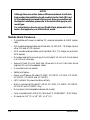
1
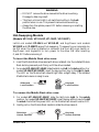
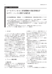
For Removable Docking Modules with 3.5"/2.5" HDD
or Optional for zip /SuperDisk LS-120/MO/TR-4 Tape
or ATA Flash Memory Reader
TM
IDE MODELS
Model VP-10LS
Model VP-10LSF
Model VP-10K
Model VP-10KF
Model VP-10KP
Model VP-10KPF
Model VP-15
TM
SCSI MODELS
Model 20LSF (SCSI 1)
Model 20KPF (SCSI 1)
Model 30KPF (Wide SCSI)
2-1 Introduction ........................................................................ 2-3
Mobile Rack Features ................................................... 2-4
Unpacking Your Mobile Rack ........................................ 2-5
IDE Basics .................................................................... 2-5
SCSI Basics .................................................................. 2-5
2-2 Hardware Installation .......................................................... 2-6
Mobile Rack Components ............................................. 2-6
Installing the Mobile Rack Docking Case (VP-15) ........... 2-7
Mounting a Drive in the Drive Case ................................ 2-8
2-3 Using the Mobile Rack ..................................................... 2-14
Non Hot-Swapping Models .......................................... 2-14
Hot-Swapping Models ................................................. 2-15
2-2
Mobile Rack
1-1 Introduction
The Mobile Rack Removable Docking Module is the perfect solution for data backup
and transporting data between computers. It is available in IDE or SCSI interface
models.
The Mobile Rack is form-fitted for a standard PC/AT 5.25" half-height bay. Its drive
case can accept most half-height 3.5" and 2.5" drives (with separately purchased
adapter cables). Not being limited by memory size, you can install any capacity drive.
This sevtion will guide you through the installation of the following Mobile Rack
Removable Docking Modules.
Mobile Rack Models:
VP-10LS
VP-10LSF
VP-10K
VP-10KF
VP-10KP
VP-10KPF
VP-15
IDE interface, Latch-lock/Slide Switch
IDE interface, Latch-lock/Slide Switch with Cooling Fan
IDE interface, Key-lock
IDE interface, Key-lock with Cooling Fan
IDE interface, Key-lock Power Switch
IDE interface, Key-lock Power Switch with Cooling Fan
IDE interface, Drive Case
VP-20LSF SCSI (50-pin) interface, Latch-lock/Slide Switch with Cooling Fan
VP-20KPF SCSI (50-pin) interface, Key-lock/Power Switch with Cooling Fan
VP-30KPF Wide SCSI (68-pin) interface, Key-lock/Power Switch with
Cooling Fan
Model Number Code Descriptions for Ordering Information:
V P - 1 0 L S (F)
1 2 3 4 5
1
2
3
4
5
Interface Type ..........
Body ........................
Lock Type ................
Power Switch ...........
Cooling Fan .............
Mobile Rack
1 = IDE, 2 = SCSI, 3 = Wide SCSI
2 = Out-Frame, 5 = In-Tray Box, 0 = Frame + Tray
L = Latch-lock, K = Key-lock
S = Latch Switch, P = Power IC Switch
F = Fan
2-3
NOTE
Although there are certain feature differences between the Mobile
Rack models, the installation for all models is similar. Both IDE and
SCSI models are documented in this manual. As you proceed through
the steps for installation, please refer to the sections that apply to your
model type.
For instructions on how to use your Mobile Rack, please refer to the
section that applies to your Mobile Rack model.
Mobile Rack Features
• Compatible with tower or desktop PC, external subsystem & RAID system
cases
• IDE models enable portable use of hard disk, LS-120, MO, TR-4 tape, zip and
other IDE and ATAPI devices
• SCSI models enable portable use of hard disk, MO, TR-4 tape, zip and other
SCSI devices
• Drive bay module for mounting a 1.0-inch height, 3.5-inch or 2.5-inch device
in a 5.25-inch drive bay
• Supports fixed 3.5-inch hard disk drives and 2.5-inch hard disk drives
(requires 2.5-inch drive adapter cable)
• Convenient pull-out handle
• Safety lock feature
• Power on/off feature (Models VP-10KP, VP-10KPF, VP-10LS, VP-10LSF,
VP-20KPF, VP-20LSF and VP-30KPF)
• LED indicator for power and drive activity
• Built-in cooling fan (Models VP-10LSF, VP-10KF, VP-10KPF, VP-20KPF,
VP-20LSF and VP-30KPF only)
• Drive case is interchangeable between all models
• Fully compatible with MS-DOS, Windows® 3.11/95/98/NT, OS/2 Warp
• Dimensions: 8.4" (D) x 5.8" (W) x 1.6" (H)
2-4
Mobile Rack
Unpacking Your Mobile Rack
Before installing the Mobile Rack, verify that the following items are included in the
carton. If any parts are damaged or missing, please contact your local dealer or sales
representative immediately.
1.
2.
3.
4.
One Mobile Rack Removable Docking Module
Eight mounting screws
2 keys (for key-lock models only)
One user’s guide
IDE Basics
IDE is an acronym for Integrated Device (Drive) Electronics and is sometimes referred
to as an ATA (AT Attachment) interface. It is the most commonly used interface for
hard disk drives installed on personal computers. Other devices like CD-ROM, tape,
optical drives, and so on have adapted a variation called ATAPI (ATA Packet Interface) and can be intermixed with standard IDE drives because they use the same
cabling and electrical interface.
Most systems today have two IDE channel connectors that are typically referred to as
primary and secondary ports. Each IDE port can have a maximum of two devices that
must be uniquely identified, typically by the setting of a jumper as a ‘master’ or ‘slave’
device.
SCSI Basics
SCSI is an acronym for Small Computer System Interface, a specification which
defines a high performance interface that distributes data among peripherals independently of the host CPU. The use of SCSI devices requires a host SCSI
controller installed in your computer.
8-bit bus width SCSI-1 and SCSI-2 controllers use 50-pin interface cabling and
support standard SCSI (5MB/sec), Fast SCSI (10MB/sec) and Ultra SCSI (20MB/
sec.) data transfer rates. Up to seven SCSI peripherals can be connected in a daisychain configuration. 16-bit bus width Wide SCSI uses 68-pin cabling, supports 20
and 40MB/sec data transfer rates, and up to 15 SCSI peripherals can be connected.
When connecting multiple SCSI peripherals, each device must be assigned a unique
SCSI ID number on the SCSI bus. ID settings for 8-bit SCSI range from ID0 to ID7
(ID7 normally assigned to the SCSI controller.) ID settings for 16-bit SCSI range
from ID0 to ID15. The device’s SCSI ID number is typically set via jumpers or
switches on most SCSI peripherals.
An important requirement, defined by the SCSI specification, is the rule of device
termination. When adding SCSI devices, you must ensure that the first and last
physical devices on the SCSI bus are terminated.
Mobile Rack
2-5
1-2 Hardware Installation
The Mobile Rack Docking Module is designed to install in any PC/AT or Pentiumclass computer that has an available 5.25-inch half-height drive bay. General
instructions for installing the Mobile Rack are given since the design of computer
cases varies. Refer to your computer’s manual whenever in doubt.
Mobile Rack Components
The Mobile Rack is comprised of two components:
Docking Case [VP-12 (L)(S)(F)(K)(P)]
Drive Case (VP-15)
Mounting
Holes
Power ON/OFF
LED Indicator
Slide-Lock/Power Switch
Drive Activity
LED Indicator
Latch-Lock Model Mobile Rack Docking Case
Mounting
Holes
Key-Lock/Power Switch
Power ON/OFF
LED Indicator
Drive Activity
LED Indicator
Key-Lock Model Mobile Rack Docking Case
2-6
Mobile Rack
Power
Connector
Data Interface
Cable
Bottom
Mounting Holes
Side
Mounting Holes
Handle
Removable Front Panel
for Removable Media Drives
Mobile Rack Drive Case VP-15 (with cover removed)
Installing the Mobile Rack Docking Case
1. Turn OFF the power to your computer and any other connected peripheral
devices. Follow the precautions for static electricity discharge:
• Discharge any static electricity build up in your body by touching a grounded
metal surface such as the computer case, if plugged in.
• During installation procedures, avoid any contact with internal parts.
2. Unplug the power cord from the back of the computer.
3. Remove your computer’s cover.
4. Remove the computer’s front cover plate from the 5.25-inch drive bay you plan
to install your Mobile Rack into.
5. Remove (separate) the Mobile Rack drive case from the docking case by lifting
the handle and pulling it out.
6. Slide the docking case into the 5.25-inch drive bay.
Mounting
Screws
Docking Case
(All Models)
Mounting
Screws
Install the Mobile Rack Docking Case into the Drive Bay
Mobile Rack
2-7
7. Position the docking case so its mounting holes align with the drive bay’s
mounting holes. Secure with the supplied mounting screws (two on
each side.)
8. Attach the data cable from the appropriate drive controller in the system.
For IDE Models: Attach an existing IDE 40-pin data cable from the system
motherboard (or IDE controller card) to the 40-pin connector on the back of the
docking case.
For SCSI Models: Depending on the SCSI Mobile Rack model, attach an
existing SCSI 50-pin or 68-pin data cable from the installed SCSI controller card
to the 50-pin or 68-pin connector on the back of the docking case.
Most connectors are keyed for proper insertion. If there is no key, orient the
cable so the pin-1 colored stripe edge is closest to the power connector.
9. Connect an available 4-pin power cable from the system’s power supply to
the 4-pin connector on the back of the docking case. The power connector is
‘D’ shaped to ensure proper orientation when making the connection.
Pin 1
40-pin IDE Connector,
50-pin SCSI Connector,
or 68-pin Wide SCSI Connector
Power Connector
Docking Module Data Cable and Power Connectors
10. Replace the computer’s cover and reconnect the power and other external
cabling.
2-8
Mobile Rack
Mounting a Drive in the Drive Case (VP-15)
Proceed with the following steps to install a 3.5-inch drive device in the Mobile Rack
drive case. (Note: a special adapter kit is required in order to install a 2.5-inch drive.)
1. Remove the Mobile Rack drive case cover by sliding it towards the back of
the unit.
Slide Cover Off
Remove the Drive Case Cover
2. If you plan to install a drive that features removable media such as a zip, TR-4 tape,
MO, LS-120 drive, or ATA Flash memory reader, carefully punch out the center
part of the front panel.
Center Part
of Front Panel
Removed
Remove Front Panel for Removable Media Drives
Mobile Rack
2-9
IMPORTANT
3. If you are installing a new hard drive into the Mobile Rack, you may need to
configure the drive before you install it.
For IDE drives: Refer to the drive manufacturer’s documentation and
configure the drive as ‘Master’, ‘Cable Select’, or ‘Slave’ depending on the
configuration of your computer. After you complete this installation, you may
also need to re-configure the computer’s BIOS Setup to make the drive functional
in the system.
For SCSI devices: Refer to the drive manufacturer’s documentation to
configure the SCSI ID number and Termination. Make sure the last SCSI device
in the internal SCSI chain is terminated. If this is not the last device, make sure
there is NO termination.
Note: If you wish to use the external SCSI ID select jumpers provided on
the Mobile Rack drive case, you must connect the 3-pin 3-wire
connector, the 2-pin black-wire common ground connector, (and for
SCSI Wide: the 2-pin gray-wire connector) from inside the drive case to
the proper pins on the SCSI device .
SCSI ID select jumpers ID1, ID2, ID4, (and ID8 for SCSI wide) are used
to set the SCSI ID on the drive case.
4. Connect the cables from the Mobile Rack drive case to the appropriate pin
connectors of the drive.
For IDE models: The drive case’s 40-pin IDE cable supports 3.5-inch
drives. Attach the power and IDE cables from the Mobile Rack drive case to the
drive. The power connector is ‘D’ shaped to correctly orient the connector.
The colored stripe on the IDE cable should be closest to the power connector.
To install a 2.5-inch drive, you must purchase a ‘44-pin to 40-pin’ connector
adapter from your local computer dealer.
2-10
Mobile Rack
For SCSI models: Connect the 4-pin power and 50- or 68-pin cables from
the Mobile Rack drive case to the drive. The power connector is ‘D’ shaped to
correctly orient the connector. The colored stripe on the data cable should be
closest to the power connector to ensure correct pin 1 orientation.
To enable the external SCSI ID selector option:
• Connect the 3-pin 3-wire connector (brown wire=ID1, red wire=ID2,
yellow wire=ID4) (and 2-pin gray-wire connector=ID8 for VP-30KPF
Wide SCSI) to the appropriate SCSI ID jumper pins on the SCSI device.
• Connect the 2-pin black-wire common ground connector to the appropriate
pins on the SCSI device.
To enable the Busy LED activity option: Connect the 2-pin 2-wire (red wire= +,
white wire= –) connector to the appropriate pins on the SCSI device.
2-pin
Busy LED
Connector
2-pin
Black-wire GND
Connector
4-pin
Power
Connector
(SCSI Wide)
2-pin Gray-wire
SCSI ID 8 Connector
3-pin
SCSI ID 1, 2, 4
Connector
50- or 68-pin
Data Cable
Connector
SCSI Drive Case Connectors
Mobile Rack
2-11
5. Carefully position the drive inside the drive case.
6. Secure the drive in place using the supplied mounting screws. Use the mounting
holes on the sides or bottom, depending on the design of the drive.
Power Cable
Colored Stripe
Mounting
Screws
Data Cable
Mounting
Screws
Install the Drive in Drive Case
7. Slide the drive case cover back on.
Mobile Rack Drive Case Ready for Use
2-12
Mobile Rack
8. For SCSI models only:
If you enabled the external SCSI ID Select feature, locate and configure the jumper
pins on the back of the drive case for the desired SCSI ID number. These four
jumpers support SCSI ID 0 to 15. This is accomplished by placing jumpers on the
appropriate number combination that would add up to the desired SCSI ID
number. For example, to set ID 5, place jumpers on ID1, and 4, where 1+ 4=5.
For wide SCSI, the ID8 option allows you to set ID numbers up to 15, for example,
1+2+8=11. See below for configuring the desired SCSI ID setting.
SCSI ID Jumper Settings
The hardware installation is complete. Your Mobile Rack drive case is ready to use.
Mobile Rack
2-13
1-3 Using the Mobile Rack
Non Hot-Swapping Models
(IDE Models VP-10K, VP-10KF
SCSI Models VP-20KPF, VP-20LSF, VP-30KPF)
IDE key-lock models VP-10K, VP-10KF and all SCSI models do not support
hot-swapping. Your computer must be POWERED OFF when the drive is inserted
or removed. Once installed, the removable drive can be used like any other drive.
To insert the Mobile Rack drive case:
1. Make sure the computer is OFF.
2. Insert the Mobile Rack drive case (with drive installed) into the installed
Mobile Rack docking case and push firmly until the drive is seated.
3. For latch-lock model VP-20LSF, slide the latch-lock left, to lock.
For key-lock models VP-10K, VP-10KF, VP-20KPF and VP-30KPF,
insert the key and turn key to the right to lock.
4. Turn your computer ON. The LED on the Mobile Rack should light after a
slight delay. The installed Mobile Rack device is ready to use.
Slide-lock
Lock Position
Key-lock
Lock Position
To remove the Mobile Rack drive case:
1. Turn your computer OFF.
2. For latch-lock model VP-20LSF, slide the latch-lock right, to unlock.
For key-lock models VP-10K, VP-10KF, VP-20KPF and VP-30KPF,
insert the key and turn key to the left to unlock.
3. Gently pull on the Mobile Rack handle to slide the drive case out.
Slide-Lock
Unlock Position
2-14
Key-lock
Unlock Position
Mobile Rack
WARNING
• DO NOT remove the drive case while the drive is working.
Damage to data may result.
• The Key-Lock and Latch-Lock switches must be in the Lock
position when in use. This prevents removal while working.
• Always turn the system power OFF before removing or inserting
the drive case.
Hot-Swapping Models
(Models VP-10LS, VP-10LSF, VP-10KP, VP-10KPF)
Latch-Lock models VP-10LS and VP-10LSF, and Key/Power Lock models
VP-10KP and VP-10KPF support hot-swapping. The power to your computer can
be ON when the drive is inserted or removed. Use the Latch-Lock switch or
Key/Power Lock keyswitch to turn power to the drive ON after inserting
it, and OFF before removing it.
To insert the Mobile Rack drive case:
1. Insert the Mobile Rack drive case (with drive installed) into the installed Mobile
Rack docking case and push firmly until the drive is seated.
2. For models VP-10LS/VP-10LSF, slide the latch-lock left, to the lock position. For
models VP-10KP/VP-10KPF, insert the key and turn key to the right to lock.
The LED on the Mobile Rack should light after a slight delay. The installed
Mobile Rack device is ready to use.
Slide-lock
Lock Position
Key-lock
Lock Position
To remove the Mobile Rack drive case:
1. For models VP-10LS/VP-10LSF, slide the latch-lock right, to the unlock
position. For models VP-10KP/VP-10KPF, insert the key and turn key to the left
to unlock. Note that the power LED on the Mobile Rack should now be OFF.
2. Gently pull on the Mobile Rack handle to slide the drive case out.
Slide-lock
Unlock Position
Mobile Rack
Key-lock
Unlock Position
2-15