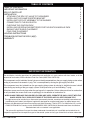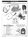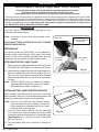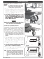
1
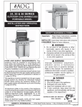
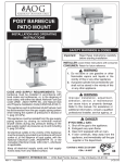
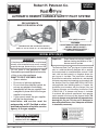
Robert H. Peterson Co. RHP OWNER’S MANUAL ® AUTOMATIC REMOTE CAPABLE SAFETY PILOT SYSTEM PRE-ASSEMBLED READY FOR INSTALLATION EPK-1(M)(P) Installed (Suitable for G4, G45, and PB series burners) (Sizes 12"- 24" for natural; 12"- 36" for propane gas) FEATURES: • NON-STANDING FLAME-SENSING PILOT • • MANUAL SWITCH ON/OFF • • OPTIONAL REMOTE CONTROL • • BATTERY OPERATION • MODEL EPK-1(M)(P) Important: WARNING If the information in this manual is not followed exactly, a fire or explosion may result, causing property damage, personal injury, or loss of life. Read these instructions carefully before starting installation of the burner control system. The Peterson Real-Fyre® gas log set is to be installed only in a solid-fuel-burning fireplace with a working flue constructed of noncombustible material. Solid fuels shall not be burned in a fireplace where this gas log set is installed. The installation, including provisions for combustion, ventilation air, and required minimum permanent vent opening, must conform with the National Fuel Gas Code (ANSI Z223.1/NFPA 54) and applicable local building codes. In Canada, the installation must conform with the Natural Gas and Propane Storage and Handling Installation Code (CSA-B-149.1). A damper stop clamp is included to maintain the minimum permanent vent opening and to prevent full closure of the damper blade. The chimney damper must be fixed fully opened when burning this log set. This log set is designed to burn with yellow flames; thus, adequate ventilation is absolutely necessary. Do not store or use gasoline or other flammable vapors and liquids in the vicinity of this or any other appliance. WHAT TO DO IF YOU SMELL GAS: • Open a window. • Do not try to light any appliance. • Do not touch any electrical switch; do not use any phone in the building. • Immediately call the gas supplier from a neighbor’s phone and follow the gas supplier’s instructions. • If you cannot reach the gas supplier, call the fire department. Installation and service must be performed by an NFI Certified or other qualified professional installer, service agency, or the gas supplier. INSTALLER & CONSUMER These instructions MUST be retained with this appliance Robert H. Peterson Co. • 14724 East Proctor Avenue • City of Industry, California 91746 Rev 3 - 0801151103 1 L-A2-10208 TABLE OF CONTENTS TABLE OF CONTENTS IMPORTANT INFORMATION EPK-1(P) PARTS LIST INSTALLATION ATTACHING THE EPK-1(P) VALVE TO THE BURNER INSTALLING THE FLAME DIVERTER BRACKET INSTALLING THE PILOT ASSEMBLY TO THE BURNER CONNECTING TO THE GAS SUPPLY CHECKING THE IGNITION PACK INSTALLING OR REPLACING BATTERIES FOR THE IGNITION MODULE PACK RADIANT HEAT SHIELD PLACEMENT PINE CONE PLACEMENT LIGHTING INSTRUCTIONS TROUBLESHOOTING THE EPK-1(M)(P) WARRANTY 2 2 3 4 4 4 5 5 6 7 7 7 8 9 10 IMPORTANT INFORMATION CHECK TO BE SURE THAT THE PROPER FUEL GAS IS BEING USED WITH THIS PILOT KIT. The installation, including provisions for combustion and ventilation air, must conform with local codes, or in the absence of local codes, with the National Fuel Gas Code (ANSI Z223.1/NFPA 54). This component and its individual shutoff valve must be disconnected from the gas-supply piping system when testing at pressures that exceed 1/2 psig. This is accomplished by closing the gas-supply line valve. This component must be isolated from the gas-supply piping system by closing its individual manual shutoff valve during any testing of the gas-supply system at test pressures up to and including 1/2 psig. A fireplace screen must be in place when the gas log set is in operation. Unless other provisions for combustion air are provided, the screen shall have an opening(s) for introduction of combustion air. WHEN GLASS FIREPLACE ENCLOSURES (DOORS) ARE USED, OPERATE THE GAS LOG SET WITH THE GLASS DOORS FULLY OPEN; BOTH SIDES IF THE FIREPLACE IS A SEE-THROUGH TYPE. This appliance may be installed in an aftermarket, permanently located, manufactured (mobile) home where not prohibited by local codes. Installation of appliances designed for manufactured homes or mobile homes must conform with Manufactured Home Construction and Safety Standard, Title 24 CFR, Part 3280 in the U.S.; or with CAN/CSA Z240 MH in Canada; or with ANSI/NCSBCS A225.1/NFPA 501A, Manufactured Home Installations Standard when such as standard is not applicable. Do not use this appliance if any part has been underwater. Immediately call a qualified service technician to inspect the appliance and to replace any part of the control system and any gas control that has been underwater. Rev 3 - 0801151103 2 L-A2-10208 EPK-1(M)(P) PARTS LIST Note: Unit is shipped pre-assembled, ready for installation. DO NOT REMOVE THE PILOT ASSEMBLY FROM THE VALVE OR PINE CONE. Parts are shown below separated for identification purposes only. 4 Input pressure tap 1 12 Pilot gas line 2 8 Output pressure tap 6 ON/OFF Switch 13 5 7 9 Velcro strips 10 14 11 3 Remote kit (if equipped) and remote instructions Photos not to scale Item No. 1. or 2. 3. 4. 5. 6. 7. 8. 9. 10. 11. 12. 13. 14. Rear view of the pine cone assembly showing battery & ignition module packs. Description Pilot assembly, natural gas Pilot assembly, propane gas Valve, natural or propane gas Ignition module pack Valve heat shield Pilot mounting bracket Screw #10 x 3/8" Phillips BLK (2) Mounting screws 10-32 x 1/4" (2) Brass adapter without plug Pine cone with switch Wire harness, 24" Batteries (D-cells) (not installed) Elbow, brass 3/8" x 3/8" Flame diverter bracket Remote kit (if equipped) Connecting a remote receiver Connect from optional remote CONNECTfemale FEMALE FROM OPTIONAL REMOTE TOmale MALEon ON EPK1- (BROWN to EPK-1(P) (brownWIRES) wires) ToOPTIONAL remote receiver TO REMOTE SYSTEM WIRINGharness HARNESS Wiring Fig. 3-1 FOR WIRING DIAGRAM & WIRE COLORS, SEE P. 6 Rev 3 - 0801151103 3 EPK1 PINE EPK-1(P) pine CONE cone L-A2-10208 INSTALLATION HOW TO INSTALL THE EPK-1(M)(P) SAFETY PILOT SYSTEM This safety pilot system must be installed by a qualified professional installer. Instructions must be followed carefully when installing to ensure proper performance and full benefit from the gas log set and safety pilot system. These instructions must be used as a supplement to the instructions supplied with the Peterson gas log set. Follow the gas log set instructions and make adjustments as appropriate for the addition of a safety pilot system. Use gas pipe sealing compound that is resistant to all gasses (or Teflon tape) and apply to all male pipe connections. Make sure that all connections are tight. Use soapy water and a brush to inspect all connections for leaks prior to use. NEVER TEST FOR LEAKS WITH AN OPEN FLAME. INSTALLATION The EPK-1(M)(P) is shipped pre-assembled for easy installation onto the burner pan. Note: Installation is easier when done outside of the fireplace. Burner pan Attach the valve to the air mixer by rotating the burner pan. FOLLOWING THESE INSTRUCTIONS WILL ENSURE PROPER INSTALLATION. PREPARATION If the burner system the EPK-1(M)(P) is to be added to is already installed, remove the logs, sand, and/or other media, and set it aside to be correctly reinstalled later using the instructions that came with the original burner system. Fuel injector or air mixer EPK-1(M)(P) valve ATTACHING THE EPK-1(M)(P) VALVE 1. Apply gas pipe sealing compound (or Teflon tape) to the male end of the fuel injector or air mixer on the burner. Fig. 4-1 2. Attach the brass adapter (Item #8) to the fuel injector or air mixer by screwing the pan onto the adapter (Fig. 4-1). Take care not to damage the attached pilot assembly when rotating the burner pan. Be sure all connections are tight. Note: The EPK-1(M)(P) valve may need to be angled slightly upward to allow for the pan to sit flat against the fireplace floor. Adjust as necessary. INSTALLING THE FLAME DIVERTER BRACKET REAR WALL When properly installed onto the burner pan, the flame diverter bracket (Item #13) will promote quicker ignition and protect the safety control system from overheating. BURNER pan Burner PAN Note: You must first install the flame diverter bracket before installing the pilot assembly. Use only the pilot assembly pre-assembled with this kit. Never substitute with an existing pilot. 1. Place the flame diverter bracket over the side edge of the burner pan, near the location the safety control system pilot bracket will be attached. It should be placed approximately 2-1/2" from the rear wall of the burner pan (see Fig. 4-2). 1/ " 22-1/2 2 FLAME Flame DIVERTER BRACKET diverter bracket Fig. 4-2 2. Tap the bracket lightly with a hammer to secure it in place. Rev 3 - 0801151103 4 L-A2-10208 INSTALLATION (Cont.) Fig. 5-1 INSTALLING THE PILOT ASSEMBLY TO THE BURNER Caution: 1. Fasten bracket to burner pan Do not kink or damage the pilot supply tube, sparking, and sensor probes. Do not unscrew the gas line from the valve. 1. The pilot assembly comes with an L-shaped mounting bracket (Item #5). Using the two black screws (Item #6), fasten the bracket to burner pan (short side toward the back of the pan) using the pre-drilled holes in the pan (see Fig. 5-1). Fig. 5-2 PILOT ASSEMBLY INSTALLED 2. Using the two (2) remaining screws (Item #7), mount the pilot assembly onto the bracket (Fig. 5-2) and tighten until snug. Check to be certain the pilot hood and probes are situated above the edge of the pan. Adjust if necessary. WARNING Keep the pilot assembly clear at all times. Never cover any part of the pilot assembly. 2. Fasten pilot assembly to bracket Fig. 5-3 CONNECTING TO THE GAS SUPPLY To connect the EPK-1(M)(P) to the gas supply, the connector kit and component parts will be needed, which are included with the burner system. Refer to the PARTS LIST in the instructions supplied with the burner to identify the key parts needed. Attach the connector to the adapter on the valve 1. Apply gas pipe sealing compound (or Teflon tape) to the male end of the gas stub. Attach the hearth elbow from the connector kit to the gas-supply stub in the fireplace. Gas connection 2. Attach the tubing of the connector kit to the elbow on the EPK-1(M)(P) control valve (see Fig. 5-3). Use Teflon tape or pipe compound. Tighten securely. (Discard the smaller connector elbow from the connector kit, as this is not needed.) 3. Connect the tubing to the hearth elbow on the gas stub. Tighten both ends securely. 4. Follow the instructions supplied with the Peterson burner system for proper burner placement. Right-side gas-supply connection Fig. 5-4 5. Turn on the gas supply and test for leaks at all connections with a soapy water solution. Never use an open flame to check for leaks. Note: Although the flex connector supplied with the burner system (not with this kit) should be sufficient for right-side supply installation (Fig. 5-4), for a left-side gas supply, a longer flex hose may be required to reach the valve (Fig. 5-5). Rev 3 - 0801151103 5 Left-side gas-supply connection Fig. 5-5 L-A2-10208 INSTALLATION (Cont.) CHECKING THE IGNITION PACK The EPK-1(M)(P) valve comes completely assembled with the wiring harness already connected to the pine cone switch assembly. However, we recommend that you follow the steps below to ensure it has not become detached during shipping before installing the batteries. Check TO CHECK THE WIRING ASSEMBLY Checkconnections connections 1. Check that the wiring harness is fitted tightly into the connector on the green ignitor pack in the rear of the pine cone (Fig. 6-1). "I"Wire wire "I" "S" wire "S" Wire B Wire Wire harness harness connector connector 2. Check that the female connectors on the two black wires from the pilot assembly (wires marked "I" and "S") are inserted fully into the male connectors on the ignitor pack (Fig. 5-1). 3. Check the connection of the red and black wires of the wire harness to the respective counterpart wires from the battery holder (red-red and black-black). The two brown wires should be connected to the switch. A Fig. 6-1 Ignitorpack pack Iginitor Note: The two (2) spare brown wires with coated male connectors are used to connect an optional remote system. Fig. 6-2 4. Check the connections of the wires to the EPK-1(M) (P) valve (see Fig. 6-2): D Orange wire marked THTP - to THTP connector on valve Black wire marked TP - to TP connector on valve Green wire marked TH - to TH connector on valve Green wire Green wire marked marked "TH" “TH” Orange Orange wire wire marked marked "THTP" “THTP” The diagram below (Fig. 6-3) shows the wiring layout for the complete unit. Black wire Black wire marked marked "TP" “TP” Check connections Check connections For installation of a remote system (if equipped), see instructions included in the remote kit and p. 3, Fig. 3-1. Switch Consult this wiring diagram to ensure correct connection of wires. Pine cone Remote Receiver (Brown-2 wires) to switch (Red) to battery holder Rev 3 - 0801151103 To pilot assembly probes I Valve magnet wire (black) (DO NOT REMOVE) I S S Orange (THTP) EPK-1(P) valve Black (TP) (Black) to battery holder Wire harness Green (TH) Fig. 6-3 Wiring diagram for EPK-1(M)(P) 6 L-A2-10208 INSTALLATION (Cont.) INSTALLING OR REPLACING BATTERIES FOR THE IGNITION MODULE PACK Two 1.5-volt (D-cell) alkaline batteries come supplied with the EPK-1(M)(P). To install or replace batteries, remove the green ignition module pack (Item #3), held in place with a Velcro strip, from rear of the pine cone receiver (Item #9). Remove battery holder and, where installed, old batteries (Item #11) from the pine cone. Install new batteries, making sure they are correctly positioned according to the diagram inside the battery holder (i.e., the flat part of the battery marked "-" on the spring). Replace holder, pressing firmly against the Velcro strip. Replace ignition pack and press firmly into place. The ignition system is now ready to operate. Fig. 7-1 Battery pack Ignitor pack Flame diverter bracket in place TURN ON THE GAS AND CHECK ALL CONNECTIONS FOR GAS LEAKS USING A SOAPY WATER SOLUTION. NEVER USE AN OPEN FLAME TO CHECK FOR GAS LEAKS. IF LEAKS ARE PRESENT, TIGHTEN DOWN CONNECTIONS UNTIL NO MORE LEAKS ARE DETECTED. Pine cone Velcro Velcro strips strips Note: For the EPK-1(M)(P) system to work properly, it is suggested that you replace the batteries annually with fresh batteries. Always replace both batteries at the same time. IMPORTANT ON/OFF ON/OFF Switch switch Valve heat shield in place Heat shield Burner pan HEAT SHIELD PLACEMENT Fig. 7-2 Cover the EPK-1(M)(P) safety valve with the heat shield as shown in Fig. 7-2. The heat shield must remain in place over the valve at all times during operation. Keep the area above the heat shield clear of logs or any other object (Fig. 7-3). Follow the log placement instructions that came with the burner exactly. Failure to follow these instructions will cause overheating in EPK-1(M)(P) safety valve components, resulting in system shutdown. Fig. 7-3 Keep area above valve clear CAUTION: DO NOT place the EPK-1(M)(P) wire bundles on, under, or near the heat shield, burner, or valve. See Fig. 7-4 for example placement. PINE CONE PLACEMENT The designer pine cone incorporating the control switch is aesthetically designed and is an integral part of the operation of the EPK-1(M)(P). The pine cone may be placed in any desired location on the valve side of the burner as long as it is always at least 4" from the flame and the wire bundle remains clear of the burner, valve, and heat shield at all times. See Fig. 7-4 for example placement. Note: Coil excess wire underneath the pine cone. CAUTION: THE PINE CONE MAY BE HOT DURING AND AFTER OPERATION. Rev 3 - 0801151103 7 Burner pan Pilot wire bundle Valve and heat shield Valve wire Wire bundles go around the bundle valve and away from the burner. Coil excess wire under Pine cone pine cone switch. Fig. 7-4 switch L-A2-10208 LIGHTING INSTRUCTIONS We recommend that before you install the log set, you familiarize yourself with the control valve layout. This will help you to be confident operating the log set when fully installed. FOR YOUR SAFETY, READ BEFORE LIGHTING WARNING If you do not follow these instructions exactly, a fire or explosion may result, causing property damage, personal injury, or loss of life. The Real-Fyre® EPK-1(P) has a pilot that is lit using the ignitor switch. When lighting the pilot, follow these instructions exactly. BEFORE LIGHTING, smell all around the gas log set area for gas. Be sure to smell next to the floor, as some gas is heavier than air and will settle on the floor. IF YOU SMELL GAS, FOLLOW THE INSTRUCTIONS ON THE FRONT COVER OF THESE INSTRUCTIONS. TO LIGHT THE BURNER SYSTEM USING THE PINE CONE SWITCH Use the switch on the top of the decorative pine cone (marked I = IGNITE; O = OFF, Fig. 8-1). 1. Press switch to I (Ignite); see Fig. 8-2. This transmits a rapid series of sparks at the pilot head and will ignite the gas. 2. Sparks cease when the pilot flame is lit and stable. After a short time, the pilot will then light the main burner. CAUTION: IF THE BURNER DOES NOT IGNITE WITHIN 20 SECONDS, STOP, WAIT 5 MINUTES, THEN REPEAT STEPS 1. AND 2. ABOVE. If the pilot will not stay lit after several tries, turn the ignitor switch to O (OFF) and call the service technician or gas supplier. Pine cone switch Fig. 8-1 Pine cone switch in ON position Fig. 8-2 Pine cone switch in OFF position Fig. 8-3 TO SHUT DOWN THE GAS LOG SET USING THE PINE CONE SWITCH Simply press the O (OFF, Fig. 8-3) switch on top of the pine cone. The gas flow will cease, and all flames (main burner and pilot) will go out (see important note below). OPERATING THE BURNER USING THE REMOTE CONTROL If your EPK-1 came equipped with a remote, or if one was added later, follow the instructions included in the remote kit for lighting and shutting down the attached burner. IMPORTANT: Both the pine cone switch and the remote control (if equipped) must be in the off state to shut the burner off. If one control is commanded off while the other is still on, the burner will remain on. Rev 3 - 0801151103 8 L-A2-10208 TROUBLESHOOTING THE EPK-1(M)(P) PROBLEM 1. Pilot will not light 2. No spark at pilot 3. Pilot lights, but main burner will not 4. Log set not bur ning properly CAUSE SOLUTION a. Obstruction in pilot gas supply or pilot gas-supply line is kinked a. Clear out obstruction. Replace pilot gassupply line if kinked b. Inadequate gas supply b. c. Air in line Have gas pressure checked by installer or gas supplier c. Air should clear; attempt to relight a. Loose wires a. Check all wires are securely in place b. Dead batteries b. Replace batteries c. Faulty switch or remote (if equipped) c. Replace the pine cone unit or remote system as appropriate a. Wire leads are not connected to proper valve terminals or toggle switch terminals not tight a. Make sure all wire leads are tight and attached to proper terminals (see wiring diagram on p. 6, Fig. 6-3) b. Batteries too low for voltage output b. Replace with new ones c. Defective valve c. Replace valve a. Low flame/uneven flame a. Check for low gas pressure; should have operating pressures of 7" w.c. for natural gas, 11" w.c. for propane at manifold b. 5. Log set shuts down during operation 6. Intermittent ignitor spark during use (main burner has been burning for well over a minute). a. Glass doors closed, causing excessive heat buildup b. Pilot electrode not properly set to pilot location c. Heat shield not in place a. Embers or sand covering pilot assembly Burner should be filled completely with sand or vermiculite a. Open glass doors b. See p. 5 (INSTALLING THE PILOT ASSEMBLY TO THE BURNER) c. Place heat shield over valve. Be sure the solid black face of the shield is between the valve and the burner a. Clear all foreign material from around the pilot assembly Periodically inspect the pilot assembly and valve controls and maintain them free of obstruction or debris. If the pilot flame is not blue with possibly yellow tips and does not impinge on the electrodes or if the pilot does not stay lit, contact a qualified professional service technician to service the pilot system. Rev 3 - 0801151103 9 L-A2-10208 FIRE MAGIC® OUTDOOR GAS GRILL LIMITED WARRANTY PLEASE COMPLETE AND RETURN YOUR REGISTRATION CARD, WHICH IS INCLUDED WITH YOUR FIRE MAGIC® GRILL LIFETIME WARRANTY - Fire Magic® cast stainless-steel burners, stainless-steel rod cooking grids, and stainless-steel housings are warranted for as long as you own your Fire Magic® grill. FIFTEEN-YEAR WARRANTY - Fire Magic® cast brass burners, brass valves, backburner assemblies (except ignition parts), and manifold assemblies are warranted for 15 years from the date of purchase of your Fire Magic® grill. THREE-YEAR WARRANTY - Fire Magic® sideburners and all other Fire Magic® grill components (except ignition and electronic parts) are warranted for three (3) years from the date of purchase of your Fire Magic® grill. Fire Magic® ignition systems (excluding batteries), electronic components (including lights and thermometers), and grill accessories are warranted for one (1) year from date of purchase. PLEASE KEEP A COPY OF YOUR SALES SLIP FOR PROOF OF PURCHASE This warranty applies to the original purchaser and to single family residential use only. It commences from date of purchase, and is valid only with proof of purchase. This warranty does not cover parts becoming defective through misuse, accidental damage, electrical damage, improper handling, storage, and/or installation. Product must be installed (and gas must be connected) as specified in the instructions or operator’s manual, by a qualified professional installer. Accessories, parts, valves, remotes, etc., when used must be Peterson Co. product. This warranty does not apply to rust, corrosion, oxidation, or discoloration, unless the affected component becomes inoperable. It does not cover labor or labor-related charges. This warranty specifically excludes liability for indirect, incidental, or consequential damages. Some states do not allow the exclusion or limitation of incidental or consequential damages, so the above exclusion may not apply to you. This warranty gives you specified legal rights, and you may have other rights that may vary from state to state. For additional information regarding this warranty, or to place a warranty claim, contact the R.H. Peterson dealer where the product was purchased. ROBERT H. PETERSON CO. Quality Check Date:___________ Orifice # (Main):__________ Orifice # (Other):__________ Leak Test: ___________ Burn Test: ___________ Gas Type: NAT. / PROPANE Model #: ___________ Serial #: ___________ Air Shutter: ___________ Inspector: ___________ Robert H. Peterson Co. • 14724 East Proctor Avenue • City of Industry, CA 91746 10