1
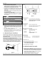
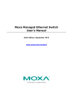
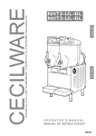
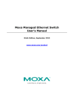
MT-2UL-BL,MT-3UL-BL
OPERATOR’S MANUAL
NS10A
MT UL BL
TABLE OF CONTENTS
1
TECHNICAL CHARACTERISTICS ................................................................................. 5
2
INTRODUCTION ............................................................................................................. 5
3
INSTALLATION ............................................................................................................... 5
4
TO OPERATE SAFELY .................................................................................................. 5
5
OPERATING PROCEDURES ......................................................................................... 6
5. 1
5. 2
5. 3
DESCRIPTION OF CONTROLS ............................................................................ 6
OPERATION HELPFUL HINTS ............................................................................. 7
CLEANING AND SANITIZING PROCEDURES ..................................................... 7
5. 3. 1 DISASSEMBLY ........................................................................................... 7
5. 3. 2 CLEANING .................................................................................................. 9
5. 3. 3 SANITIZING ................................................................................................ 9
5. 3. 4 ASSEMBLY ................................................................................................. 9
5. 4 IN-PLACE SANITIZATION ................................................................................... 10
6
ROUTINE MAINTENANCE ........................................................................................... 10
6. 1
7
MAINTENANCE (TO BE CARRIED OUT BY QUALIFIED SERVICE PERSONNEL ONLY) ..... 10
DEFROST TIMER (OPTIONAL) ................................................................................... 11
This dispenser is manufactured under one or more of the following U.S.patents and/or
other pending patents:
U.S.A. 4,900,158
U.S.A. 4,696,417
U.S.A. 5,713,214
U.S.A. 5,906,105
3
MT UL BL
MT 2 UL BL
MT 3 UL BL
1 TECHNICAL CHARACTERISTICS
n
2
3
Gal
2.5
2.5
5-
width
Inches
14.25
21
6-
depth
Inches
18.5
18.5
height
Inches
Transparent removable bowls
Capacity of each bowl, approx.
3-
4-
Dimensions:
27.75 27.75
Net weight, approx.
kg
81.5
108
Gross weight, approx.
kg
95
125
Adjustable thermostats
n
2
3
Hermetic compressor
Air-cooled condenser
Safety pressure switch
damage is found, call the delivering carrier immediately to
file a claim.
Install the unit on a counter top that will support the
combined weight of dispenser and product bearing in
mind what is stated in the preceding point 1
IMPORTANT warning.
A minimum of 15 cm (6”) of free air space all around the
unit should be allowed to guarantee adequate ventilation.
Ensure that the legs are screwed tightly into the base of
the machine.
Replace the standard legs originally installed with the 100
mm (4”) legs whenever they are provided with the unit.
Before plugging the unit in, check if the voltage is the same
as that indicated on the data plate. Plug the unit into a
grounded, protected single phase electrical supply
according to the applicable electrical codes and the
specifications of your machine. When the unit has no plug,
install a proper grounded plug, in compliance with
electrical codes in force in your area, suitable to at least
10 Amp 250 Volt (220-230 Volts 50-60 Hz areas) and
20 Amp 25 0 Vol t (1 00-1 15 Vol ts 5 0-6 0 Hz area s)
applications. Should you prefer to connect the unit directly
to the mains, connect the supply cord to a 2-pole wall
breaker, whose contact opening is at least 0.125”. Do not
use extension cords.
Noise level lower than 70 dB (A)
ATTENTION
IMPORTANT
Read electrical ratings written on the data plate of the
individual units; the data plate is adhered on the
dispensing side panel of the unit, just behind the drip
tray (the right side drip tray in multiple bowl models).
The serial number of the unit (preceded by the
symbol #) is adhered inside the left switch box. Data
plate specifications will always supersede the
information in this manual.
The electric diagram of the dispenser is located in the
inner part of the dispensing side panel.
Specifications are subject to change without notice.
2 INTRODUCTION
Please read all sections of this manual thoroughly to familiarize
yourself with all aspects of the unit.
Like all mechanical products, this machine will require cleaning
and maintenance. Besides, dispenser working can be
compromised by operator’s mistakes during disassembly and
cleaning. It is strongly recommended that personnel
responsible for the equipment’s daily operations, disassembly,
cleaning, sanitizing and assembly, go through these
procedures in order to be properly trained and to make sure
that no misunderstandings exist.
Failure to provide proper electrical ground according to
applicable electrical codes could result in serious shock
hazard.
7 - The unit doesn’t come presanitized from the factory.
Before serving products, the dispenser must be
disassembled, cleaned and sanitized. according to this
handbook
instructions
(chapter
5.3 CLEANING AND SANITIZING PROCEDURES).
4 TO OPERATE SAFELY
1 - Do not operate the dispenser without reading this
operator’s manual.
2 - Do not operate the dispenser unless it is properly
grounded.
3 - Do not use extension cords to connect the dispenser.
4 - Do not operate the dispenser unless all panels are
restrained with screws.
5 - Do not obstruct air intake and discharge openings: 15 cm
(6”) minimum air space all around the dispenser.
6 - Do not put objects or fingers in panels louvers and faucet
outlet.
7 - Do not remove bowls, augers and panels for cleaning or
routine maintenance unless the dispenser is disconnected
from its power source.
5 OPERATING PROCEDURES
3 INSTALLATION
1 - Remove the corrugate container and packing materials
and keep them for possible future use.
IMPORTANT
When handling the machine never grasp it by the bowls
or by the evaporator cylinders. The manufacturer
refuses all responsibilities for possible damages which
may occur through incorrect handling.
2 - Inspect the uncrated unit for any possible damage. If
ATTENTION
In case of damages, the power cord must be replaced
by qualified personnel only in order to prevent any
shock hazard.
1 - Clean and sanitize the unit according to the instructions in
this manual. See chapter 5.3 CLEANING AND
SANITIZING PROCEDURES.
2 - Fill the bowls with product to the maximum level mark. Do
not overfill.
The exact quantity of product (expressed as liters and
5
MT UL BL
gallons) is shown by marks on the bowl.
3 - In case of products to be diluted with water, pour water into
bowl first, then add correct quantity of product. In case of
natural squashes, it is advisable to strain them, in order to
prevent pulps from obstructing the faucet outlet.
4 - To obtain the best performance and result, use bases
designed to be run in Granita freezers. Such bases have a
sugar content of 34 degrees Baumé corresponding to 64
degrees Brix.
For soft drinks the bases are to be diluted with more water,
on a 1 plus 5/5.5 basis.
In any case follow the syrup manufacturer’s instructions for
both Granita and soft drink recipes.
If natural juices (e.g. lemon, orange) as well as sugarless
products (e.g. coffee) are used, dissolve 5.3 - 7 oz of sugar
per 0.25 gallons.
follows:
figure 2
IMPORTANT
However Granita mix may be done, its Brix (sugar
percent content) must be at least 13.
Power switch (A)
0 position
:
I position
:
IMPORTANT
Operate the dispenser with food products only.
5 - Install the covers and check that they are correctly placed
over the bowls. The dispenser must always run with the
covers installed to prevent a possible contamination of the
product.
6 - Set the control switches as shown in chapter
5.1 DESCRIPTION OF CONTROLS.
7 - Always leave the dispenser on, as the refrigeration stops
automatically when Granita reaches the proper thickness.
The mixers will continue to turn.
Light switch (E)
0 position
:
I position
:
power is turned ON to all functions
and the other switches are enabled.
The fan motor runs.
all top cover lights are OFF.
all top cover lights are ON, provided
that power switch (A) is set to I.
Mixer/refrigeration switch (B)
I position
: mixer and refrigeration ON.
SOFT DRINK mode.
0 position
:
OFF.
II position
:
mixer and refrigeration ON.
GRANITA mode.
5. 1 DESCRIPTION OF CONTROLS
The dispenser is equipped with a power switch and a light
switch. In addition each bowl is individually operated by a
mixer/refrigeration switch. In fact it is possible to dispense both
soft drinks and Granita.
When a bowl is in Soft Drink mode the beverage temperature
is controlled by the corresponding thermostat.
When a bowl is in Granita mode the mix viscosity is controlled
by the corresponding adjustment screw located in the rear wall
of each container (for temperature and viscosity setting make
reference to chapter 5.2 OPERATION HELPFUL HINTS).
All the switches are located on the faucet side of the dispenser
in switch panels protected by switch covers (see figure 1).
power is turned OFF to all functions.
Thermostat (D)
Turn clockwise
Turn counterclockwise
: to decrease temperature
: to increase temperature
To operate the unit:
1 - Set the power switch to I position.
2 - Set the mixer/refrigeration switches as follows:
- to the I position to get soft drink.
- to the II position to get Granita.
3 - Set the light switch to I position.
5. 2 OPERATION HELPFUL HINTS
1 - Granita viscosity adjustment: proper Granita viscosity is
factory preset. To change the viscosity, if needed, use a
standard screwdriver to turn the adjustment screw located
in the rear wall of each container as follows (see figure 3):
figure 1
With reference to figure 3 dispenser controls functions are as
6
- towards right (clockwise) to obtain a thicker product (the
indicator F will go down in opening G).
- towards left (counterclockwise) to obtain a thinner
product (the indicator F will go up in opening G).
MT UL BL
11 -Restrictor cap: when the unit is used in Soft Drink mode it
is advisable to install the restrictor cap on the faucet outlet
in order to reduce the drink outflow (see figure 4).
figure 3
2 - Beverage temperature adjustment: proper beverage
temperature is factory preset. To reset, turn the knob
located in each switch box as follows:
- towards right (clockwise) to decrease temperature.
- towards left (counterclockwise) to increase temperature.
Note: beverage temperature is controlled by the
t h e r m o s t a t o n l y w h e n t h e mi x e r / r e f r i g e r a t i o n
switch(es) are in I position, Soft Drink mode.
3 - When the mixer / refrigeration switch(es) are set in I
position, Soft Drink mode, it is possible to manually switch
off the refrigeration by turning completely towards left
(counterclockwise) the thermostat knob until it clicks.
4 - The length of time for freeze down of Granita is governed
by many variables, such as ambient temperature, mix
initial temperature, sugar content (Brix level) and viscosity
setting.
5 - To shorten Granita recovery time and increase
productivity, it is advisable to pre-chill the product to be
used in the dispenser.
6 - To shorten Granita recovery time and increase
productivity, the bowl should be refilled after the product
level drops lower than half of the evaporator cylinder and
at the start of each day.
7 - For good product conservation the dispenser must run
overnight, at least in Soft Drink mode.
If this is not possible and product is left in the bowls
overnight, the mixer/refrigeration switches must be set to
the I position at least one hour before the unit is switched
off. This eliminates any block of iced product forming
overnight, which could result in damage to mixers or to
their motor when the unit is switched back on. In any case,
before the unit is restarted, make sure that no blocks of ice
have been formed; if so, they are to be removed before the
unit is switched on. Overnight operation in drink mode also
eliminates possible ice accumulation from condensation all
around the bowls.
8 - Mixers must not be turned off when frozen product is in the
bowl: if not agitated, the product may freeze to a solid
block of ice. If the mixers are turned back on in this
situation, damage to the mixers and their motor may result.
Therefore, mixers may be restarted only after product is
melted.
9 - The dispenser is equipped with a magnetic coupling by
which the gear motor (located outside the bowl) drives the
mixers (inside the bowl).
The magnetic drive operates as an “intelligent clutch” able
to automatically disconnect the mixers in case they are
seized by ice or other causes.
This inconvenience can be soon noticed since an
intermittent dull noise warns that mixers are still.
In this case it is necessary to unplug immediately the
dispenser, empty the bowl and eliminate the cause of
seizing.
10 -The dispenser must be able to emit heat.
In case it seems excessive, check that no heating source
is close to the unit and air flow through the slotted panels is
not obstructed by wall or boxes. Allow at least 15 cm (6”) of
free clearance all around the dispenser.
figure 4
5. 3 CLEANING AND SANITIZING
PROCEDURES
1 - Cleaning and sanitizing of the dispenser are
recommended to guarantee the conservation of the best
product taste and the highest unit efficiency. This section
is a procedural guideline only and is subject to the
requirements of the local Health Authorities.
2 - Prior to the disassembly and cleaning, the machine must
be emptied of product. To do this proceed as follows:
- set the power switch to I position
- set mixer/refrigeration switch(es) to I position (Soft Drink
mode)
- place a pail under each faucet and drain all product from
bowls
- set all control switches to the 0 position.
5. 3. 1 DISASSEMBLY
ATTENTION
Before any disassembly and/or cleaning procedure
make sure that the dispenser is disconnected from its
power source.
1 - Remove cover from the bowl.
2 - Remove the bowl by lifting its faucet side up and off the
fastening hooks (see figure 5) and slide it out (see figure
6).
figure 5
7
MT UL BL
4 - Remove the bowl gasket from its seat (see figure 9).
figure 6
3 - Slide the outer spiral out (see figure 7) and then the inside
auger (see figure 8).
figure 9
5 - Dismantle the faucet assembly (see figure 10).
figure 7
figure 10
6 - Slide the drip tray out and empty it.
5. 3. 2 CLEANING
ATTENTION
Before any disassembly and/or cleaning procedure
make sure that the dispenser is disconnected from its
power source.
figure 8
IMPORTANT
Do not attempt to wash any machine components in a
dishwasher.
1 - Prepare at least two gallons of a mild cleaning solution of
warm (45-60 °C / 120-140 °F) potable water and
dishwashing detergent. Do not use abrasive detergent.
Important: if present, follow label directions, as too strong
a solution can cause parts damage, while too mild a
8
MT UL BL
solution will not provide adequate cleaning.
wall (see figure 12).
IMPORTANT
In order to prevent any damages to the dispenser use
only a detergent suitable with plastic parts.
2 - Using a brush, suitable for the purpose, thoroughly clean
all disassembled parts in the cleaning solution.
ATTENTION
When cleaning the machine, do not allow excessive
amounts of water around the electrically operated
components of the unit. Electrical shock or damage to
the machine may result.
figure 12
3 - Do not immerse the lighted top covers in liquid. Wash them
apart with the cleaning solution. Carefully clean their
undersides.
4 - In the same manner clean the evaporator cylinder(s) using
a soft bristle brush.
5 - Rinse all cleaned parts with cool clean water.
5 - Insert the auger into the evaporator taking care to
accompany it to the end so as to prevent it from hitting
against the rear wall (see figure 13).
5. 3. 3 SANITIZING
Sanitizing should be performed immediately prior to starting
the machine. Do not allow the unit to sit for extended periods of
time after sanitization.
1 - Wash hands with a suitable antibacterial soap.
2 - Prepare at least two gallons of a warm (45-60 °C / 120140 °F) sanitizing solution (100 PPM available chlorine
concentration or 1 spoon of sodium hypoclorite diluted with
half a gallon of water) according to your local Health
Codes and manufacturer’s specifications.
3 - Place the parts in the sanitizing solution for five minutes.
4 - Do not immerse the lighted top covers in liquid. Carefully
wash their undersides with the sanitizing solution.
5 - Place the sanitized parts on a clean dry surface to air dry.
6 - Wipe clean all exterior surfaces of the unit. Do not use
abrasive cleaner.
figure 13
5. 3. 4 ASSEMBLY
1 - Slide the drip tray into place.
2 - Lubricate faucet piston, inside auger and outer spiral (see
points A, B and C of figure 11) only with the grease
supplied by the manufacturer or other food grade
approved lubricant.
figure 11
3 - Assemble the faucet by reversing the disassembly steps
(see figure 10)
4 - Fit bowl gasket around its seat.
Note: the largest brim of gasket must face against the rear
6 - Install the outer spiral. Slide it over the evaporator until its
front notch engages with the exposed end of the auger
shaft (see figure 14).
figure 14
7 - Push the bowl towards the rear wall of the unit until it fits
snugly around the gasket and its front fastening hooks are
9
MT UL BL
properly engaged (see figure 15).
the two plastic coated screws (see figure 16).
figure 16
figure 15
3 - Replacement of lighted top cover bulb: remove the fixing
screw placed in the upper part of the top cover, remove the
lower part and replace the bulb (using a 24-28V 21W max
bulb). Reassemble the top cover and replace the fixing
screw.(see figure 17)
8 - Use fresh product to chase any remaining sanitizer from
the bottom of the bowl(s). Drain this solution. Do not rinse
out the machine.
5. 4 IN-PLACE SANITIZATION
The In-Place Sanitization prior to starting the machine may be
performed, if needed, only as further precaution, in addition to
the Disassembled Parts Sanitization described before, but
never in lieu of it.
1 - Prepare two gallons of a warm (45-60°C / 120-140 °F)
sanitizing solution (100 PPM available chlorine
concentration or 1 spoon of sodium hypoclorite diluted with
half a gallon of water) according to your local Health
Codes and manufacturer’s specifications.
2 - Pour the solution into the bowl(s).
3 - Using a brush suitable for the purpose, wipe the solution
on all surfaces protruding above the solution-level and on
the underside of the top cover(s).
4 - Install the top cover(s) and operate the unit. Allow the
solution to agitate for about two minutes. Drain the solution
out of the bowl(s).
5 - Use fresh product to chase any remaining sanitizer from
the bottom of the bowl(s). Drain this solution. Do not rinse
out the machine.
figure 17
ATTENTION
Condenser fins are very sharp. Use extreme caution
when cleaning.
6. 1 MAINTENANCE (TO BE CARRIED OUT
BY QUALIFIED SERVICE PERSONNEL
ONLY)
1 - Daily: inspect the machine for signs of product leaks past
seals and gaskets. If proper assembly does not stop leaks
around seals or gaskets, check for improper lubrication,
worn or damaged parts. Replace parts as needed.
2 - Monthly on MT 1P, MT 2 and MT 3 models: remove the
dust from the condenser filter. A blocked filter will reduce
1 - Annually: remove the panels and clean the inside of the
machine including the base, side panels, condenser, etc.
2 - Never remove the insulating jacket from around the
suction tubing of the evaporator (the copper tubing located
on the right side of gear motor). In case the insulating
jacket is missing replace the entire parts with original
spare parts from the supplier.
3 - In order to prevent any damages to the dispenser, all
plastics parts must be lubricated only with grease supplied
by the manufacturer or with another lubricating product
suitable for polycarbonate.
ATTENTION
IMPORTANT
Before any disassembly and/or cleaning procedure
make sure that the dispenser is disconnected from its
power source by unplugging it or switching off the 2pole wall breaker.
The electric diagram of the dispenser is located in the
inner part of the dispensing side panel.
6 ROUTINE MAINTENANCE
performance and could cause compressor failure.
Remove the only left panel (from faucet side) unscrewing
10
7 DEFROST TIMER (OPTIONAL)
The Defrost Timer, located on the right side of the unit,
MT UL BL
automatically switches the dispenser from Granita mode to
Soft Drink mode and the opposite. This means that during
defrost periods frozen Granita will melt to thermostat setting
temperature and once defrost period has expired, the product
automatically freezes down again to Granita setting viscosity.
figure 18
To operate the defrost timer proceed as follows (see figure 18).
1 - Set the time of the day by rotating the dial clockwise (arrow
A). Never rotate the timer counterclockwise as this
would damage the internal mechanism. Align the current
time of day with the arrow B on the timer face. This is a 24
hour timer showing both A.M. and P.M.
2 - Program the defrost timer by pushing out on the tabs C
that correspond to the hours desired to defrost. Each tab
represents 15 minutes. A minimum of four to eight hours
are required to defrost frozen beverage (depending on
ambient conditions).
Note: when all the tabs are pushed in the defrost function is
OFF (the machine operates as if it were not equipped with
Defrost Timer).
11
SPARE PARTS LIST
2422_49 V 1.4 07N17
MT UL
BLACK
1
00263
Transparent cover
29
>>>
Starting-run capacitor
55
00177
Fixing ring
2
00638
Bowl
30
00158
Rubber leg
56
00132
Thermostat
3
00420
Faucet piston
30
00092
4” leg
57
00182
Thermostat knob
4
00101
Faucet piston OR
31
>>>
Solenoid valve coil
58
PPP
Transformer
5
00640
Black faucet handle
33
00087
Density adjustment screw
59
00231
Insulation foam
6
00447
Faucet handle spring
34
00720
Shaped nut
60
00449
PWB housing
7
00498
Black faucet handle pin
35
00088
Spring
61
00520
Lighted top cover (assy.)
8
00536
Thrust washer rubber cap
36
00121
Microswitch
62
00269
Timer switch
9
00653
Bowl gasket
37
00227
Rear wall rear bushing
63
00134
Restrictor cap
10
00126
Rear wall front bushing
38
00229
Magnetic drive washer
64
00255
Central shaft OR
11
00127
Auger bushing
39
00228
Magnetic drive
66
00704
Gear motor
12
00110
Black auger
40
00230
Flange bushing
67
00046
Rear bushing
13
00111
Outer spiral
41
00226
Flange OR 3231
68
00153
Black rear cover
14
00499
Black switch box
42
00183
Gear motor flange
69
00589
Black rear cover fixing screw
15
00500
Black power switch box
43
00448
Delay electronic device (PWB)
70
00517
Warning light
16
PPP
Dispensing side panel
44
PPP
Black back panel
73
00119
Black panel fixing screw
17
00504
Black switch box cover
45
00513
MT 1P-2-3 black side panel
76
00519
Stainless steel fixing screw for panel
18
00123
3-position switch
45
00514
MT 1P-2-3 black side panel for defrost 77
timer
00532
Timer cover
19
00124
2-position switch
46
00515
Black lighted top cover (upper)
78
00463
Solenoid valve plastic cap
20
00265
Terminal block with cable clamp
47
00572
"Strawberry" graphic for top cover
79
00648
"All Fruit" graphic for rear cover
21
00179
Clip
47
00647
"All Fruit" graphic for top cover
79
00574
"Strawberry" graphic for rear cover
22
00297
Terminal block protection
48
00188
Picture screen
80
00575
Rear cover picture screen
23
PPP
Fan motor
49
00094
Lighted top cover (lower)
81
00537
Thrust washer
24
00133
Fan blade
50
00084
Top cover light contact
25
PPP
Black drip tray cover
51
00100
28V bulb
26
PPP
Black drip tray
52
00131
Bulb socket + bracket
PPP
See next table
27
>>>
Relay
53
00529
Light wire
>>>
Please order what printed on piece
28
>>>
Overload protector
54
00533
Flexible contact
PPP
16
23
25
26
43
44
58
MT 2 UL
00502
00108
00588
00587
00113
00511
00193
MT 3 UL
00503
00108
00588
00587
00081
00512
00194
GEAR MOTOR SPARE PARTS LIST
1
00097
Bracket with bush
10
00247
Ball bearing ý 28 mm
20
00721
Gear box cover
2
00156
Stator
11
00257
1.5 mm spacer
22
00180
Rotor
3
00296
Stator protection gasket
12
00184
Third gear
23
00187
Pinion
4
00168
Washer
13
00165
Fourth gear
24
00169
Bushing
5
00253
Rotor spacer
14
00258
3.3 mm spacer
25
00170
Washer
6
00190
Gear box with bushing
15
00224
Bushing rubber cap
26
00262
Bracket screw
7
00256
Seal retainer
17
00164
First gear
8
00254
Ball bearing ý 28 mm rubber cap
18
00167
Second gear
9
00255
Central shaft OR
19
00636
Gasket
MT UL BL
NOTES:
15
CECILWARE CORPORATION
43-05 20th Avenue
Long Island City, N.Y. 11105
Tel. (800) 935 2211
Fax (718) 932 7860
[email protected]
www.cecilware.com
2422_49 R1.7 07N17