1
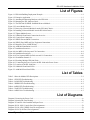
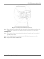
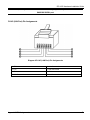
IES-1000
Integrated Ethernet Switch
July 2002
Version 2.04
Hardware Installation Guide
IES-1000 Hardware Installation Guide
Copyright
IES-1000 Integrated Ethernet Switch
Copyright © 2002 by ZyXEL Communications Corporation.
The contents of this publication may not be reproduced in any part or as a whole, transcribed, stored in a retrieval
system, translated into any language, or transmitted in any form or by any means, electronic, mechanical, magnetic,
optical, chemical, photocopying, manual, or otherwise, without the prior written permission of ZyXEL
Communications Corporation.
Published by ZyXEL Communications Corporation. All rights reserved.
Disclaimer
ZyXEL does not assume any liability arising out of the application or use of any products, or software described
herein. Neither does it convey any license under its patent rights nor the patent rights of others. ZyXEL further
reserves the right to make changes in any products described herein without notice. This publication is subject to
change without notice.
Trademarks
Trademarks mentioned in this publication are used for identification purposes only and may be properties of their
respective owners.
ii
Copyright
IES-1000 Hardware Installation Guide
ZyXEL Limited Warranty
ZyXEL warrants to the original end user (purchaser) that this product is free from any defects in materials or
workmanship for a period of up to two (2) years from the date of purchase. During the warranty period and upon
proof of purchase, should the product have indications of failure due to faulty workmanship and/or materials,
ZyXEL will, at its discretion, repair or replace the defective products or components without charge for either parts
or labor and to whatever extent it shall deem necessary to restore the product or components to proper operating
condition. Any replacement will consist of a new or re-manufactured functionally equivalent product of equal
value, and will be solely at the discretion of ZyXEL. This warranty shall not apply if the product is modified,
misused, tampered with, damaged by an act of God, or subjected to abnormal working conditions.
Note
Repair or replacement, as provided under this warranty, is the exclusive remedy of the purchaser. This warranty is
in lieu of all other warranties, express or implied, including any implied warranty of merchantability or fitness for a
particular use or purpose. ZyXEL shall in no event be held liable for indirect or consequential damages of any kind
of character to the purchaser.
To obtain the services of this warranty, contact ZyXEL's Service Center for your Return Material Authorization
number (RMA). Products must be returned Postage Prepaid. It is recommended that the unit be insured when
shipped. Any returned products without proof of purchase or those with an out-dated warranty will be repaired or
replaced (at the discretion of ZyXEL) and the customer will be billed for parts and labor. All repaired or replaced
products will be shipped by ZyXEL to the corresponding return address, Postage Paid. This warranty gives you
specific legal rights, and you may also have other rights that vary from country to country.
ZyXEL Limited Warranty
iii
IES-1000 Hardware Installation Guide
Customer Support
If you have questions about your ZyXEL product or desire assistance, contact ZyXEL Communications
Corporation offices worldwide, in one of the following ways:
Contacting Customer Support
When you contact your customer support representative, have the following information ready:
♦ Model and serial number.
♦ Warranty information.
♦ Date you received your product.
♦ Brief description of the problem and the steps you took to solve it.
METHOD
E-MAIL
SUPPORT/SALES
TELEPHONE/FAX
WEB SITE/ FTP SITE
REGULAR MAIL
LOCATION
WORLDWIDE
[email protected]
+886-3-578-3942
www.zyxel.com
www.europe.zyxel.com
[email protected]
+886-3-578-2439
ftp.europe.zyxel.com
[email protected]
+1-714-632-0882
800-255-4101
www.zyxel.com
[email protected]
+1-714-632-0858
ftp.zyxel.com
SCANDINAVIA
[email protected]
+45-3955-0700
www.zyxel.dk
[email protected]
+45-3955-0707
ftp.zyxel.dk
GERMANY
[email protected]
+49-2405-6909-0
www.zyxel.de
[email protected]
+49-2405-6909-99
ZyXEL Deutschland GmbH.
Adenauerstr. 20/A4 D-52146
Wuerselen, Germany
[email protected]
+603-795-44-688
www.zyxel.com.my
[email protected]
+603-795-34-407
Lot B2-06, PJ Industrial Park,
Section 13, Jalan Kemajuan,
46200 Petaling Jaya Selangor
Darul Ehasn, Malaysia
NORTH
AMERICA
MALAYSIA
iv
ZyXEL Communications Corp.,
6 Innovation Road II, ScienceBased Industrial Park, Hsinchu,
300 Taiwan
ZyXEL Communications Inc.,
1650 Miraloma Avenue,
Placentia, CA 92870, U.S.A.
ZyXEL Communications A/S,
Columbusvej 5, 2860 Soeborg,
Denmark
Customer Support
IES-1000 Hardware Installation Guide
Table of Contents
Copyright .................................................................................................................................................................... ii
ZyXEL Limited Warranty ....................................................................................................................................... iii
Customer Support..................................................................................................................................................... iv
List of Figures........................................................................................................................................................... vii
List of Tables ............................................................................................................................................................ vii
Preface...................................................................................................................................................................... viii
Chapter 1
IES-1000 Applications..................................................................................................................... 1-1
1.1
Applications .............................................................................................................................................. 1-1
1.1.1
MTU Application .............................................................................................................................. 1-1
1.1.2
Enterprise Application....................................................................................................................... 1-2
Chapter 2
Hardware Installation..................................................................................................................... 2-1
2.1
Environment.............................................................................................................................................. 2-1
2.1.1
Operating Environment ..................................................................................................................... 2-1
2.1.2
Storage Environment......................................................................................................................... 2-1
2.2
Free-standing IES-1000 Installation Requirements .................................................................................. 2-1
2.3
Rack-mounted IES-1000 Installation Requirements ................................................................................. 2-1
2.4
Mounting the IES-1000 on a Rack ............................................................................................................ 2-1
2.4.1
Attaching the Mounting Brackets to the IES-1000 ........................................................................... 2-2
2.4.2
Mounting the IES-1000 on a Rack .................................................................................................... 2-2
Chapter 3
Removing and Installing Network Modules ................................................................................. 3-1
3.1
Removing a G.SHDSL SAM1008 Network Module................................................................................. 3-1
3.2
Installing a Network Module..................................................................................................................... 3-2
Chapter 4
IES-1000 Connections ..................................................................................................................... 4-1
4.1
Front Panel Connections ........................................................................................................................... 4-1
4.2
Console Port .............................................................................................................................................. 4-1
4.3
SHDSL Port Connections.......................................................................................................................... 4-2
4.3.1
Procedure to Complete a G.SHDSL Connection .............................................................................. 4-2
Notes About MDFs (Main Distribution Frames) .......................................................................................... 4-4
4.4
ADSL Port Connections............................................................................................................................ 4-5
4.4.1
Typical Scenarios .............................................................................................................................. 4-6
4.4.2
Installation Scenario A ...................................................................................................................... 4-6
Procedure To Connect To An MDF.............................................................................................................. 4-7
4.4.3
Installation Scenario B ...................................................................................................................... 4-7
Procedure To Connect To MDFs .................................................................................................................. 4-9
4.4.4
Installation Scenario C .................................................................................................................... 4-10
Procedure To Connect To MDFs ................................................................................................................ 4-11
4.4.5
LAN Port (Ethernet) Connection .................................................................................................... 4-12
4.4.6
Power Cord...................................................................................................................................... 4-12
Chapter 5
Turning On Your IES-1000............................................................................................................ 5-1
5.1
Introduction ............................................................................................................................................... 5-1
5.2
Network Module Front Panel LEDs.......................................................................................................... 5-2
Chapter 6
Hardware Troubleshooting ............................................................................................................ 6-1
Table of Contents
v
IES-1000 Hardware Installation Guide
6.1
System Startup...........................................................................................................................................6-1
6.1.1
The SYS LED Does Not Turn On .....................................................................................................6-1
6.2
The ALM LED Is On.................................................................................................................................6-1
6.3
The SHDSL LED(s) Do Not Turn On .......................................................................................................6-2
6.4
The ADSL LED(s) Do Not Turn On..........................................................................................................6-2
6.5
The LAN LED(s) Do Not Turn On ...........................................................................................................6-3
6.6
There Is No Voice on an ADSL Connection..............................................................................................6-3
Appendix A Removing and Installing a Fuse.......................................................................................................... A
Appendix B Pin Assignments ................................................................................................................................... D
Appendix C Hardware Specifications ......................................................................................................................F
Index .............................................................................................................................................................................I
vi
Table of Contents
IES-1000 Hardware Installation Guide
List of Figures
Figure 1-1 IES-1000 Building Deployment Example............................................................................................... 1-2
Figure 1-2 Enterprise Application ............................................................................................................................. 1-3
Figure 2-1 Attaching the Mounting Brackets to the IES-1000.................................................................................. 2-2
Figure 2-2 Mounting the IES-1000 on a Rack .......................................................................................................... 2-3
Figure 3-1 The IES-1000 G.SHDSL SAM1008 Network Module............................................................................ 3-1
Figure 3-2 Loosen Module Screws ........................................................................................................................... 3-1
Figure 3-3 Removing a Network Module from the IES-1000 Chassis ..................................................................... 3-2
Figure 3-4 Installing a Network Module into the IES-1000 Chassis ........................................................................ 3-3
Figure 3-5 Tighten Module Screws........................................................................................................................... 3-3
Figure 4-1 SAM1008 Front Panel Connections Overview ....................................................................................... 4-1
Figure 4-2 Console Port Connection......................................................................................................................... 4-2
Figure 4-3 SHDSL Port and MDF Connections ....................................................................................................... 4-3
Figure 4-4 SHDSL Port, MDF and User Equipment Connections............................................................................ 4-4
Figure 4-5 Magnified View of MDF Wiring ............................................................................................................. 4-5
Figure 4-6 AAM1008 Installation Overview ............................................................................................................ 4-6
Figure 4-7 Installation Scenario A ............................................................................................................................ 4-7
Figure 4-8 One MDF for End-user and CO Connections ......................................................................................... 4-8
Figure 4-9 Installation Scenario B ............................................................................................................................ 4-9
Figure 4-10 Two Separate MDFs for End-user and CO Connections..................................................................... 4-10
Figure 4-11 Installation Scenario C......................................................................................................................... 4-11
Figure 4-12 Stacking Multiple IES-1000 Units ...................................................................................................... 4-12
Figure 4-13 Connecting the Power Cord to the IES-1000 and a Power Source...................................................... 4-13
Figure 5-1 Location of the IES-1000 Fans................................................................................................................ 5-1
Figure 5-2 SAM1008 Front Panel LEDs................................................................................................................... 5-2
Figure 5-3 AAM1008 Front Panel LEDs .................................................................................................................. 5-2
List of Tables
Table 5-1 Network Module LED Descriptions ......................................................................................................... 5-2
Table 6-1 SYS LED Troubleshooting ....................................................................................................................... 6-1
Table 6-2 ALM LED Troubleshooting ...................................................................................................................... 6-1
Table 6-3 SHDSL LED Troubleshooting .................................................................................................................. 6-2
Table 6-4 ADSL LED Troubleshooting..................................................................................................................... 6-2
Table 6-5 LAN LED Troubleshooting ...................................................................................................................... 6-3
Table 6-6 ADSL Voice Troubleshooting ................................................................................................................... 6-3
List of Diagrams
Diagram 1 Removing the Power Cord .........................................................................................................................A
Diagram 2 Opening the Fuse Housing .........................................................................................................................B
Diagram 3 Locations of the Installed and Spare Fuses ................................................................................................C
Diagram 4 RJ-11 4P4C (Console Port) Pin Assignments ............................................................................................D
Diagram 5 RJ-11 6P2C (SHDSL Port) Pin Assignments .............................................................................................D
Diagram 6 RJ-45 (LAN Port) Pin Assignments ........................................................................................................... E
Lists of Figures, Diagrams and Tables
vii
IES-1000 Hardware Installation Guide
Preface
Congratulations on your purchase of the IES-1000 Integrated Ethernet switch.
This guide shows you how to set up the hardware for your IES-1000.
About the IES-1000
The IES-1000 is an integrated Ethernet switch that multiplexes traffic from up to 16 G.SHDSL or ADSL
subscribers (or eight of each) into two 10/100M Ethernet ports that connect to a WAN network via a WAN
switch.
Syntax Conventions
“Enter” means for you to type one or more characters and press the carriage return. “Select” or “Choose” means
for you to select one from the predefined choices.
For brevity’s sake, we will use “e.g.” as shorthand for “for instance”, and “i.e.” as shorthand for “that is” or “in
other words” throughout this manual.
Related Documentation
User’s Guide
The User’s Guide explains firmware setup, management and maintenance procedures.
Glossary and ZyXEL Web Site
Please refer to www.zyxel.com for an online glossary of networking terms or the ZyXEL download library for
additional support documentation.
viii
Preface
IES-1000 Hardware Installation Guide
Chapter 1
IES-1000 Applications
This chapter describes IES-1000 applications and basic operating environment.
1.1
Applications
The following are typical DSL multiplexing applications of the IES-1000.
1. Multiple Tenant Unit (MTU)
2. Enterprise
1.1.1
MTU Application
The following figure depicts a typical application of the IES-1000 in a large residential building, or Multiple
Tenant Unit (MTU), that leverages existing phone line wiring to provide Internet access to all tenants.
A tenant connects a computer to the phone line in a unit using a G.SHDSL or ADSL modem. The other end of the
phone line is connected to a port on the IES-1000. The IES-1000 aggregates the traffic from the tenants to the
Ethernet port and forwards it to a router or switch. The router (or switch) then routes the traffic further to the
Internet.
IES-1000 Applications
1-1
IES-1000 Hardware Installation Guide
Figure 1-1 IES-1000 Building Deployment Example
1.1.2
Enterprise Application
The IES-1000 can also be used in any-sized company to multiplex traffic from employee G.SHDSL or ADSL
connections to the Internet. Multiplex traffic from up to 16 connections and use a hub or switch to multiplex more.
1-2
IES-1000 Applications
IES-1000 Hardware Installation Guide
Figure 1-2 Enterprise Application
IES-1000 Applications
1-3
IES-1000 Hardware Installation Guide
Chapter 2
Hardware Installation
This chapter shows you how to install hardware for a free-standing or rack-mounted scenario.
2.1
Environment
The following are the recommended environments for the IES-1000.
2.1.1
Operating Environment
Temperature: 0 — 50°C; Humidity: 5% — 95% (non-condensing)
2.1.2
Storage Environment
Temperature: -25 - 70°C; Humidity: 5% - 95% (non-condensing)
Refer also to the Hardware Specification Appendix.
2.2
Free-standing IES-1000 Installation Requirements
Position the IES-1000 on a flat surface. Remember that the unit requires proper ventilation.
2.3
Rack-mounted IES-1000 Installation Requirements
•
Two mounting brackets (supplied).
•
Eight M3 flat head screws (supplied) and a #2 Philips screwdriver.
•
Four M5 flat head screws and a #2 Philips screwdriver.
2.4
Mounting the IES-1000 on a Rack
Precautions:
•
Make sure the rack will safely support the combined weight of all the equipment it contains.
•
Make sure the position of the IES-1000 does not make the rack unstable or top-heavy. Take all
necessary precautions to anchor the rack securely before installing the unit.
Hardware Installation
2-1
IES-1000 Hardware Installation Guide
2.4.1
Step 1.
Attaching the Mounting Brackets to the IES-1000
Position a mounting bracket on one side of the IES-1000, lining up the four screw holes on the bracket
with the screw holes on the side of the unit (see the figure shown next).
Failure to use the proper screws may damage the unit.
Figure 2-1 Attaching the Mounting Brackets to the IES-1000
Step 2.
Using a #2 Philips screwdriver, install the M3 flat head screws that came with the brackets through the
mounting bracket holes into the IES-1000.
Step 3.
Repeat Step 1 and Step 2 to install the second mounting bracket on the other side of the unit.
You may now mount the IES-1000 on a rack. Proceed to the next section.
2.4.2
Step 1.
Mounting the IES-1000 on a Rack
Position a mounting bracket (that is already attached to the IES-1000) on one side of the rack, lining up
the two screw holes on the bracket with the screw holes on the side of the rack (see the figure shown
next).
Failure to use the proper screws may damage the unit.
2-2
Hardware Installation
IES-1000 Hardware Installation Guide
Figure 2-2 Mounting the IES-1000 on a Rack
Step 2.
Using a #2 Philips screwdriver, install the M5 flat head screws through the mounting bracket holes into
the rack.
Step 3.
Repeat Step 1 and Step 2 to attach the second mounting bracket on the other side of the rack.
Hardware Installation
2-3
IES-1000 Hardware Installation Guide
Chapter 3
Removing and Installing Network Modules
This chapter shows you how to remove and install network modules.
Each IES-1000 accommodates up to two network modules. Remove and install modules via the front of the IES1000. The figure below shows the front view of a SAM1008 network module; the procedures for removing and
installing AAM1008 network modules are the same.
Figure 3-1 The IES-1000 G.SHDSL SAM1008 Network Module
3.1
Step 1.
Removing a G.SHDSL SAM1008 Network Module
Loosen the two screws on the front panel that secure the module to the chassis by turning them counterclockwise as show next.
Figure 3-2 Loosen Module Screws
Step 2.
Gently pull the network module out of the chassis as shown next.
Removing and Installing Network Modules
3-1
IES-1000 Hardware Installation Guide
Figure 3-3 Removing a Network Module from the IES-1000 Chassis
3.2
Installing a Network Module
Step 1.
Hold the module with the network ports facing you and insert it into an empty slot located on the front
of the IES-1000 as shown next.
Step 2.
Push the bottom of the front of the module into the IES-1000. The front of the module should be flush
with the IES-1000 chassis.
3-2
Removing and Installing Network Modules
IES-1000 Hardware Installation Guide
Figure 3-4 Installing a Network Module into the IES-1000 Chassis
The front of the network module must be flush with the front of the IES-1000 after you install a
network module or it will not work!
Step 3.
Secure the module to the chassis by turning the two screws on the front of the module clockwise as
shown next.
Figure 3-5 Tighten Module Screws
Removing and Installing Network Modules
3-3
IES-1000 Hardware Installation Guide
Chapter 4
IES-1000 Connections
This chapter shows you how and where to make hardware connections.
Before you make your hardware connections, make sure that your IES-1000 is safely and securely positioned.
4.1
Front Panel Connections
All connections are made on the front panel of the IES-1000. The following figure shows the front panel
connections of the SAM1008. A more detailed discussion follows. Connections for the AAM1008 are the same
except for the DSL ports (see 4.4 for details).
Figure 4-1 SAM1008 Front Panel Connections Overview
4.2
Console Port
For the initial configuration, you need to use terminal emulator software on a computer and connect it to a
network module through the console port. Connect the mini-RJ-11 end of the console cable to the console port of
the network module. Connect the other end to a serial port of your computer. After the initial setup, you can
modify the configuration remotely through Telnet connections.
Hardware Connections
4-1
IES-1000 Hardware Installation Guide
Figure 4-2 Console Port Connection
4.3
SHDSL Port Connections
The SHDSL ports connect to an MDF (Main Distribution Frame) and end-user equipment via telephone wire.
•
For detailed specifications about the associated RJ-11 connector, refer to the Pin Assignment appendix.
•
For more detail about MDF connections refer to the Notes About MDFs (Main Distribution Frames)
shown later in this section.
The procedure shown next explains how to complete a single G.SHDSL connection (SAM1008) to an MDF via an
SHDSL port. Instructions on ADSL connections (AAM1008) come later.
4.3.1
Procedure to Complete a G.SHDSL Connection
Step 1.
Connect the RJ-11 end of a telephone wire to the SHDSL port on the front panel of the SAM1008 as
shown next.
Step 2.
Connect the other end of the telephone wire to the upper port of an MDF (Main Distribution Frame)
using a punch-down tool.
4-2
Hardware Connections
IES-1000 Hardware Installation Guide
Figure 4-3 SHDSL Port and MDF Connections
Step 3.
Connect a different telephone wire to the lower port of the MDF using a punch-down tool.
Step 4.
Connect the other (RJ-11) end of the telephone wire to the end-user G.SHDSL modem/router.
When you finish this procedure your connections should look similar to the figure shown next. Connections
between the user’s computer and modem/router are not described here.
Hardware Connections
4-3
IES-1000 Hardware Installation Guide
Figure 4-4 SHDSL Port, MDF and User Equipment Connections
Notes About MDFs (Main Distribution Frames)
An MDF is usually installed between end-users’ equipment and the telephone company (CO) in a basement or
telephone room. The MDF is the point of termination for the outside telephone company lines coming into a
building and the telephone lines in the building.
4-4
Hardware Connections
IES-1000 Hardware Installation Guide
Figure 4-5 Magnified View of MDF Wiring
Connect wiring from end-user equipment to the lower ports of an MDF using a telephone wire. Connect wiring
from the telephone company to the upper ports of an MDF (see the previous figure).
Some MDFs have surge protection circuitry built in between the two banks; thus, do not connect telephone wires
from the telephone company directly to the IES-1000.
Use a punch-down tool to seat telephone lines between MDF blocks.
This chapter details how to connect ADSL wiring to MDFs based on your existing telephone wiring
infrastructure.
4.4
ADSL Port Connections
The AAM1008 network module can provide ADSL and voice services over the same telephone wiring. It also has
built in splitters that save space and simplify installation.
The following figure gives an example of a basic installation scenario for using the AAM1008 to combine voice
and data signals.
Hardware Connections
4-5
IES-1000 Hardware Installation Guide
Figure 4-6 AAM1008 Installation Overview
You can also use RJ-11 connectors on both ends of the telephone cables connect directly to an
ADSL modem(s) or patch panel. This chapter discusses connections using MDFs.
4.4.1
Typical Scenarios
Your existing telephone wiring usually depends on your region. Here are descriptions of three typical installation
scenarios. See the Notes About MDFs (Main Distribution Frames) for more information about MDFs. Use
telephone wires with RJ-11 jacks on one end (follow the pin assignments shown in the Pin Assignments Appendix)
for connecting to the AAM1008.
4.4.2
Installation Scenario A
You want to install the AAM1008 network module in an environment where there are no previously installed
MDFs. There is no phone service and you want to install the AAM1008 for data-access only. No connections
from the CO ports are necessary.
You may connect using an MDF or attach RJ-11 connectors to the non-AAM1008 side of the telephone wire and
then connect to ADSL modem directly.
4-6
Hardware Connections
IES-1000 Hardware Installation Guide
Figure 4-7 Installation Scenario A
Procedure To Connect To An MDF
Step 1.
Connect the RJ-11 connector end of a telephone wire to one of the USER ports on the AAM1008.
Step 2.
Connect the other end of the telephone wire to the upper ports of the MDF using a punch-down tool.
Step 3.
Connect the telephone wiring from each end-user’s ADSL modem to the lower ports of the MDF.
4.4.3
Installation Scenario B
Phone service is available. There is one MDF from which end-users CO connections are made (see next figure).
Hardware Connections
4-7
IES-1000 Hardware Installation Guide
Figure 4-8 One MDF for End-user and CO Connections
Please refer to the following figure for the connection schema.
MDF 1 is the original MDF used for telephone connections only.
MDF 2 is used for telephone connections only.
MDF 3 is for ADSL service connections.
Change the wiring (in the following figure) from MDF 1 to MDF 3 for telephone subscribers who
want ADSL service.
4-8
Hardware Connections
IES-1000 Hardware Installation Guide
Figure 4-9 Installation Scenario B
Procedure To Connect To MDFs
Step 1.
Acquire two additional MDFs (MDFs 2 and 3).
Step 2.
Connect the RJ-11 connector ends of telephone wires you want for ADSL service to the USER ports on
the AAM1008.
Step 3.
Connect the other ends of the telephone wires to the upper ports of MDF 3 using a punch-down tool.
Step 4.
Connect the telephone wiring from the end-user’s ADSL modem(s) to the lower ports of MDF 3.
Step 5.
Connect the RJ-11 connector ends of telephone wires you want for phone service to the AAM1008
ports labeled CO.
Step 6.
Connect the other ends of the telephone wires to the lower ports of MDF 2 using a punch-down tool.
Step 7.
Connect the upper ports of MDF 2 to the lower ports of MDF 1 using regular telephone wiress.
Step 8.
Connect the upper ports of MDF 1 to the telephone company.
Step 9.
Telephone subscribers only (that is, non-ADSL subscribers) retain connections to the lower ports of
MDF 1.
Step 10. Change the wiring from MDF 1 to MDF 3 for telephone subscribers who want ADSL service.
Hardware Connections
4-9
IES-1000 Hardware Installation Guide
4.4.4
Installation Scenario C
Phone service is also available but there are two MDFs; one for end-user telephone line connections and the other
one for CO telephone line connections (see the following figure).
Users A and B have telephone (only) service.
Figure 4-10 Two Separate MDFs for End-user and CO Connections
Please refer to the following figure for the ADSL connection schema.
MDFs 1 and 2 are the two original MDFs.
MDFs 3 and 4 are two additional MDFs you need.
User A still has telephone service only. User B now has ADSL service also (see the following
figure).
4-10
Hardware Connections
IES-1000 Hardware Installation Guide
Figure 4-11 Installation Scenario C
Procedure To Connect To MDFs
Step 1.
Acquire two additional MDFs (3 and 4).
Step 2.
Connect the RJ-11 connector ends of telephone wires you want for ADSL service to the USER ports on
the AAM1008.
Step 3.
Connect the other ends of the telephone wires to the upper ports of MDF 3 using a punch-down tool.
Step 4.
Connect the lower ports of MDF 3 to the upper ports of MDF 2 for those users that want ADSL service.
(Users who want telephone service only, retain the original connection from the top port of MDF 2 to
the bottom port of MDF 1.)
Step 5.
Connect the telephone wiring from the end-user’s ADSL equipment to the lower ports of MDF 2.
Step 6.
Connect the RJ-11 connector ends of telephone wires you want for voice service to the AAM1008’s
CO ports.
Step 7.
Connect the other ends of the telephone wires to the lower ports of MDF 4 using a punch-down tool.
Step 8.
Connect the top ports of MDF 4 to the bottom ports of MDF 1 using regular telephone wires.
Hardware Connections
4-11
IES-1000 Hardware Installation Guide
Connect the top ports of MDF 1 to the telephone company.
4.4.5
LAN Port (Ethernet) Connection
Connect the LAN port of your SAM1008 to an Ethernet WAN switch using a straight-through Category 5 UTP
(Unshielded Twisted Pair) cable with RJ-45 connectors. Connect the other end of the cable to an Ethernet switch.
You may stack multiple IES-1000 units up to the number of ports available on the Ethernet switch as shown next.
Figure 4-12 Stacking Multiple IES-1000 Units
4.4.6
Power Cord
Connect the female end of the power cord to the power receptacle on the front panel of your IES-1000 (to the right
of the fuse housing) as shown next. Connect the other end of the cord to a power outlet. Make sure that no objects
obstruct the airflow of the fans (locatd on the side of the unit).
4-12
Hardware Connections
IES-1000 Hardware Installation Guide
Make sure you use a 100-240VAC/1A, 50/60Hz power source.
Figure 4-13 Connecting the Power Cord to the IES-1000 and a Power Source
Hardware Connections
4-13
IES-1000 Hardware Installation Guide
Chapter 5
Turning On Your IES-1000
This chapter discusses the fans and LEDs of the IES-1000 after you turn it on.
5.1
Introduction
Before turning on your IES-1000, make sure you:
•
Have attached a computer to the IES-1000 serial port as explained previously.
•
Can see the status LEDs on the front panel while you view the VT100 terminal emulator.
Push the power switch (located at the front of the IES-1000) to the ON or “|” position. The IES-1000 will
automatically run a self-test that takes approximately 20 seconds. The SYS LED will remain on if your IES-1000
has started normally.
If the SYS LED does not turn on then recheck your connections or refer to the Hardware
Troubleshooting chapter.
Make sure you can feel and/or hear the fans working — working fans emit a low buzz and blow air. The fans are
located on the IES-1000 as shown next. Refer to the Hardware Troubleshooting chapter to test the fans if they are
not working.
See the next section to interpret the operational status of your IES-1000.
Figure 5-1 Location of the IES-1000 Fans
Turning On Your IES-1000
5-1
IES-1000 Hardware Installation Guide
5.2
Network Module Front Panel LEDs
The following figures show the front panels of the network modules. LEDs describe the operational status of your
network module. Please also refer to the Hardware Troubleshooting chapter to see how LEDs may aid in
troubleshooting.
Figure 5-2 SAM1008 Front Panel LEDs
Figure 5-3 AAM1008 Front Panel LEDs
Table 5-1 Network Module LED Descriptions
LED
COLOR
STATUS
ALM
Red
On
The module has overheated.
Off
The module is functioning within normal temperature parameters.
SYS
SHDSL (1-8)
Green
Green
or ADSL (1-8)
LAN
Green
Yellow
5-2
Blinking
DESCRIPTION
The system is initializing.
On
The module is on and functioning properly.
Off
The system is not receiving power, is not ready or has a malfunction.
On
The DSL link is up.
Off
The DSL link is down.
Blinking
The system is transmitting/receiving to/from a 10 Mbps Ethernet network.
On
The link to a 10 Mbps Ethernet network is up.
Off
The link to a 10 Mbps Ethernet network is down.
Blinking
The system is transmitting/receiving to/from a 100 Mbps Ethernet network.
On
The link to a 100 Mbps Ethernet network is up.
Off
The link to a 100 Mbps Ethernet network is down.
Turning On Your IES-1000
IES-1000 Hardware Installation Guide
Chapter 6
Hardware Troubleshooting
This chapter explains how to troubleshoot IES-1000 hardware. Refer also to the Troubleshooting
chapter in the User’s Guide .
6.1
System Startup
When you turn on the IES-1000, it automatically runs a self-test that takes approximately 20 seconds. The SYS
LED will remain on if your IES-1000 has started normally.
6.1.1
The SYS LED Does Not Turn On
Table 6-1 SYS LED Troubleshooting
STEP
CORRECTIVE ACTION
1
Make sure the power cord is connected properly to the power outlet. Make sure you are using the
correct power source (100 watts maximum, 100-240VAC/1A, 50/60Hz).
2
Make sure the power connector and power wire on the IES-1000 are connected properly.
3
Make sure the network module is properly connected to the IES-1000 (refer to Chapter 3 ).
4
Make sure the fuse is not burnt-out. Replace the fuse if it is burnt out. Refer to the Removing and
Installing a Fuse appendix.
5
The LED itself or the unit may be faulty; contact your vendor.
6.2
The ALM LED Is On
The ALM (alarm) lights when the IES-1000 is overheated and/or the fans are not working properly and/or voltage
readings are outside the tolerance levels.
Table 6-2 ALM LED Troubleshooting
STEP
1
CORRECTIVE ACTION
Make sure you can feel and/or hear the fans working - working fans emit a low buzz and blow air.
If the fans are not working properly, make sure the power connector is connected properly.
Contact your vendor if the fans do not work. Do not remove fans from the IES-1000. Only a qualified
distributor should remove or repair fans.
Hardware Troubleshooting
6-1
IES-1000 Hardware Installation Guide
6.3
The SHDSL LED(s) Do Not Turn On
The SHDSL LEDs show the operational status of SHDSL port connections. If the SHDSL LED is off, it means the
link to the SHDSL modem/router is down or there is not a connection to the SHDSL port.
Table 6-3 SHDSL LED Troubleshooting
STEP
CORRECTIVE ACTION
1
Ensure that all hardware connections are correctly installed (including the modem/router on the
subscriber’s side) and that all devices are turned on.
2
Make sure the SAM1008 SHDSL port is enabled (refer to the User’s Guide or Quick Start Guide). The
SHDSL ports are disabled by default.
3
Check the SHDSL line pin assignments shown in the Pin Assignments appendix.
4
Check the telephone wire connections between the G.SHDSL modem/router and the MDF(s).
5
Check the telephone wire and connections between the MDF(s) and ADSL port(s).
6
Check the telephone wire mapping on the MDF(s) – see section Step 4.
7
Make sure the in-house wiring works and is connected properly (refer to Chapter 4 ).
8
Make sure the line speed is consistent between the IES-1000 side and the CPE (Customer Premise
Equipment) side.
9
If your line quality is low, you may need to select a slower line speed for both the IES-1000 and CPE
sides. Refer to the User’s Guide.
10
Repeat the steps above using a different SHDSL port.
6.4
The ADSL LED(s) Do Not Turn On
The ADSL LEDs show the operational status of ADSL port connections. If the ADSL LED is off, it means the link
to the ADSL modem/router is down or there is not a connection to the ADSL port.
Table 6-4 ADSL LED Troubleshooting
STEP
CORRECTIVE ACTION
1
Ensure that all hardware connections are correctly installed (including the modem/router on the
subscriber’s side) and that all devices are turned on.
2
Make sure the AAM1008 ADSL port is enabled (refer to the User’s Guide or Quick Start Guide). The
ADSL ports are disabled by default.
3
Check the ADSL line pin assignments shown in the Pin Assignments appendix.
4
Check the telephone wire connections between the ADSL modem/router and the MDF(s).
5
Check the telephone wire and connections between the MDF(s) and ADSL port(s).
6
Check the telephone wire mapping on the MDF(s) – see section Step 4.
7
Make sure the in-house wiring works and is connected properly (refer to Chapter 4 ).
8
Make sure the upstream and downstream line rates are consistent between the IES-1000 side and the
CPE (Customer Premise Equipment) side.
6-2
Hardware Troubleshooting
IES-1000 Hardware Installation Guide
Table 6-4 ADSL LED Troubleshooting
STEP
CORRECTIVE ACTION
9
If your line quality is low, you may need to select slower upstream and downstream line rates for both
the IES-1000 and CPE sides. Refer to the User’s Guide.
10
Repeat the steps above using a different ADSL port.
6.5
The LAN LED(s) Do Not Turn On
Table 6-5 LAN LED Troubleshooting
STEP
CORRECTIVE ACTION
1
Make sure the LAN port of your network module is connected to an Ethernet WAN switch with a
straight-through Category 5 UTP (Unshielded Twisted Pair) cable with RJ-45 connectors.
2
The factory default settings for the LAN (Ethernet) port of the network module are:
Speed: Auto
Duplex: Auto
Flow control: Auto
If the IES-1000’s auto-negotiation is turned off, an Ethernet port uses the pre-configured speed and
duplex mode when making a connection, thus requiring you to make sure that the settings of the WAN
switch Ethernet port are in the same order to connect.
6.6
There Is No Voice on an ADSL Connection
The AAM1008 has internal POTS (Plain Old Telephone Service) splitters and CO side RJ-11 ports that allow the
telephone wiring used for ADSL connections to also simultaneously carry normal voice conversations.
Table 6-6 ADSL Voice Troubleshooting
STEP
CORRECTIVE ACTION
1
Make sure the subscriber has a POTS splitter properly installed.
2
Check the ADSL line pin assignments shown in the Pin Assignments appendix.
3
Check the telephone wire connections between the subscriber and the MDF(s).
4
Check the telephone wire and connections between the MDF(s) and USER port(s).
5
Check the telephone wire and connections between the MDF(s) and the CO port(s). Check the
connection from the MDF(s) to the telephone company or the PBX.
6
Check the telephone wire mapping on the MDF(s) – see section Step 4.
7
Make sure the in-house wiring works and is connected properly (refer to Chapter 4 ).
8
Repeat the steps above using a different ADSL port.
Hardware Troubleshooting
6-3
IES-1000 Hardware Installation Guide
Appendix A
Removing and Installing a Fuse
This appendix shows you how to remove and install fuses for the IES-1000.
The IES-1000 uses one 250V-3A fuse. The IES-1000 comes with two 250V-3A fuses; one is installed at the
factory (in the fuse housing) and the other is a spare (also located inside the fuse housing). If you need to install a
new fuse, follow the procedure below.
Before you begin, you will need:
•
A small flat head screwdriver
•
A 250V 3A fuse
•
Good lighting
Removing and Installing Fuses
Removing Fuses
Safety first! Disconnect all power from the IES-1000 before you begin this procedure.
Step 1.
Place the front panel of the IES-1000 in front of you.
Step 2.
Remove the power cord from the back of the unit for easy access to the fuse housing as shown next.
Diagram 1 Removing the Power Cord
Appendix A Removing and Installing a Fuse
A
IES-1000 Hardware Installation Guide
Step 3.
Using a small flat head screwdriver, gently pry open the right side of the fuse housing (located to the
left of the power cord port receptacle) as shown next.
Diagram 2 Opening the Fuse Housing
Step 4.
B
Gently pull the fuse casing from the IES-1000. The installed fuse is located attached to, and on the
outside of the fuse housing; the spare fuse is located inside the fuse housing.
Appendix A Removing and Installing a Fuse
IES-1000 Hardware Installation Guide
Diagram 3 Locations of the Installed and Spare Fuses
Step 5.
Remove the burnt-out fuse from the IES-1000. A burnt-out fuse is blackened, darkened or cloudy inside
its glass casing. A working fuse has a completely clear glass casing. Dispose of the burnt-out fuse.
Installing Fuses
Step 1.
After removing the burnt-out fuse, gently push the replacement fuse into the same location as the old
fuse until you hear a click.
Step 2.
Firmly, but gently, push the fuse housing back into the IES-1000 housing until you hear a click.
Step 3.
Plug the power cord back into the IES-1000.
Appendix A Removing and Installing a Fuse
C
IES-1000 Hardware Installation Guide
Appendix B
Pin Assignments
Mini RJ-11 4P4C (Console Port) Pin Assignments
Diagram 4 RJ-11 4P4C (Console Port) Pin Assignments
RJ-11 6P2C (SHDSL Ports on the SAM1008 and ADSL USER or CO Ports on the
AAM1008) Pin Assignments
Diagram 5 RJ-11 6P2C (SHDSL Port) Pin Assignments
D
Appendix B PIN Assignments
IES-1000 Hardware Installation Guide
Note that a 2, 4 or 6 pin connector can be used with this port provided pins 3 and 4 connect to a
SAM1008 SHDSL port.
RJ-45 (LAN Port) Pin Assignments
Diagram 6 RJ-45 (LAN Port) Pin Assignments
1 = TX+
8 = Not Connected
2 = TX-
7 = Not Connected
3 = RX+
6 = RX-
4 = Not Connected
5= Not Connected
Appendix B PIN Assignments
E
IES-1000 Hardware Installation Guide
Appendix C
Hardware Specifications
Physical Interfaces
IES-1000
•
Two slots for a total of up to two hot-swappable xDSL network modules
•
Power receptacle
•
19” 1U rack-mountable, wall-mountable unit
•
Each network module has one mini RJ-11 console port for local configuration and management
SAM1008 G.SHDSL Network Module
•
Eight RJ-11 6P2C interfaces for G.SHDSL service that conform to the G.991.2 standard
•
One mini-RJ-11 4P4C interface for local console connection
•
One RJ-45 10/100Base-TX auto-negotiation interface. This Fast Ethernet port is compliant with
IEEE802.3 and IEEE802.3u standards
•
LED indicators for system status, overheat warning (ALM), 10/100M Ethernet (LAN) and G.SHDSL
interface status
AAM1008 ADSL Network Module
•
Eight RJ-11 6P2C interfaces for ADSL service
•
One mini-RJ-11 4P4C interface for local console connection
•
One RJ-45 10/100Base-TX auto-negotiation interface. This Fast Ethernet port is compliant with
IEEE802.3 and IEEE802.3u standards
•
LED indicators for system status, overheat warning (ALM), 10/100M Ethernet (LAN) and ADSL
interface status
Other Hardware Features
•
Built-in fans
•
Temperature sensors for temperature monitoring
•
Surge protection to prevent lightening damage
Dimensions
440mm (W) x 320mm (D) x 44.45mm (H)
Weight
F
•
One IES-1000 (no modules) = 3.6 kg
•
One SAM1008 = .8 kg
Appendix C Hardware Specifications
IES-1000 Hardware Installation Guide
•
One AAM1008 = 1.1 kg
Power Consumption
•
60 watts maximum
•
100-240VAC/1A, 50/60Hz
Fuse Rated
•
T3A 250VAC
Operating Environment
•
Temperature: 0ºC — 50ºC
•
Humidity: 5% — 95%
Storage Environment
•
Temperature: -25ºC — 70ºC
•
Humidity: 5% — 95%
Appendix C Hardware Specifications
G
IES-1000 Hardware Installation Guide
Index
#
E
#2 Philips screwdriver............................. 2-1, 2-2, 2-3
Enable the DSL port............................................... 6-2
1
F
10 Mbps Ethernet ................................................... 5-2
Fans .................................................................5-1, 6-1
100 Mbps Ethernet ................................................. 5-2
Location ............................................................. 5-1
A
Flow control ........................................................... 6-3
AAM1008 Connections ......................................... 4-5
Free-standing.......................................................... 2-1
AC INPUT ........................................................... 4-12
Front Panel
ADSL Connections ................................................ 4-5
LEDs .................................................................. 5-2
ADSL MDF Connections....................................... 4-5
Front Panel Connections ........................................ 4-1
ADSL Modem........................................................ 1-1
Console Port....................................................... 4-1
ADSL Port.............................................................. 6-2
Ethernet ............................................................ 4-12
Airflow ................................................................. 4-12
Overview............................................................ 4-1
ALM................................................................5-2, 6-1
Fuse .......................................................... 6-1, A, B, C
Applications ........................................................... 1-1
Type ......................................................................A
Enterprise ....................................................1-1, 1-2
Fuse Rated.................................................................G
MTU............................................................1-1, 1-2
G
Auto-negotiation .................................................... 6-3
G.SHDSL modem ...........................................6-2, 6-3
C
G.SHDSL Modem.................................................. 1-1
CO .......................................................................... 4-5
G.SHDSL Port ....................................................... 6-2
COM1..................................................................... 4-1
H
COM2..................................................................... 4-1
Hardware Connections........................................... 4-1
Console Port Connection........................................ 4-2
Hardware Installation............................................. 2-1
Copyright .................................................................. ii
Hardware Specifications
Customer Support..................................................... iv
Operating Environment - Humidity ......................G
D
Operating Environment - Temperature .................G
Dimensions................................................................ F
Storage Environment - Humidity ..........................G
Disclaimer ................................................................. ii
Storage Environment - Temperature.....................G
Duplex .................................................................... 6-3
Hardware Troubleshooting .................................... 6-1
Index
I
IES-1000 Hardware Installation Guide
I
Rack-Mounted IES-1000 Installation.....................2-1
IES-1000.................................................................viii
Read Me First .........................................................viii
Installing a Network Module..................................3-2
Rear Panel Connections
Installing Fuses......................................................... C
Power Cord.......................................................4-13
Integrated Ethernet Switch ........................................ii
Rear Panel ........................................................4-13
L
Related Documentation ..........................................viii
LED
Removing and Installing A Fuse .............................. A
DSL ............................................................ 6-2, 6-3
Removing and Installing Network Modules ..........3-1
Lightening .................................................................F
Removing Fuses ....................................................... A
M
Before you Begin ................................................. A
M3 flat head screws................................................2-1
Opening the Fuse Housing ....................................B
M5 flat head screws........................................ 2-1, 2-3
Repair .......................................................................iii
MDF (Main Distribution Frame)............. 4-2, 4-4, 4-5
Replacement .............................................................iii
MDF Blocks ...........................................................4-5
Residential Building Application ...........................1-1
Mounting Brackets ......................................... 2-2, 2-3
Return Material Authorization number (RMA) .......iii
MTU .......................................................................1-1
RJ-11 .................................................. 4-1, 4-2, 4-3, D
O
RJ-45 .............................................................4-12, 6-3
Operating Environment ..........................................2-1
run a self-test ..........................................................6-1
P
S
Physical Interfaces.....................................................F
SAM 1008 Network Modules ................................3-1
Pin Assignments ....................................................... D
Screws ....................................................................2-2
RJ-11 (Console Port) ............................................ D
sensors ....................................................................... F
RJ-11 (SHDSL Port) ............................................ D
Service......................................................................iii
RJ-45 (LAN Port ...................................................E
SHDSL ............................................. 4-2, 4-3, 4-4, 5-2
Power Consumption ................................................. G
SHDSL Port ............................................ 4-2, 6-2, 6-3
Power Switch..........................................................5-1
SHDSL Port(s) .......................................................4-2
Power Wires ...........................................................3-1
Speed ......................................................................6-3
Preface ....................................................................viii
stack......................................................................4-12
Punch Down Tool...................................................4-5
Straight-through Category 5 UTP (Unshielded
Twisted Pair) Cable...................................4-12, 6-3
R
Rack Mounting .......................................................2-2
Precautions .........................................................2-1
J
Syntax Conventions................................................viii
SYS ......................................................... 5-1, 5-2, 6-1
Index
IES-1000 Hardware Installation Guide
SYS LED................................................................ 6-1
W
T
WAN Link ............................................................. 6-3
Telnet ..................................................................... 4-1
Warning Sticker ................................................... 4-12
Temperature .............................................................. F
Weight....................................................................... F
Trademarks................................................................ ii
Working Fans......................................................... 6-1
Turning On Your IES-1000 ................................... 5-1
Z
U
ZyXEL Limited Warranty........................................ iii
User’s Guide....................................................viii, 6-1
Index
K