1
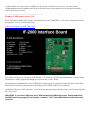
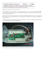
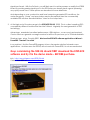
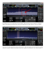
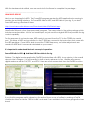
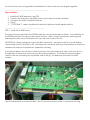
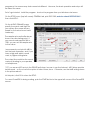
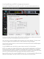
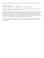
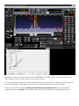
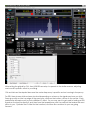
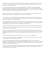
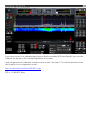
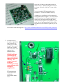
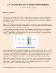
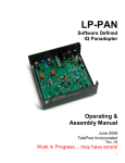
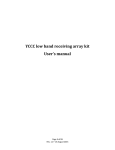
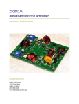
Adding Pan-adapter Capability to the Yaesu FT-2000/FT-950 Jeff Blaine – ACØC – v2 - Dec 2009 A great deal is made over the Flex series click-tune and bandscope capabilities. The same features can be added to the FT-2000 as well providing possibly the best of both worlds – all the convenience of the bandscope and quick navigation – combined with the traditional feel of “hands on knobs.” Following is a summary of how to get the FT2000 configured to have band scope service. The capability of the band scope depends on how much time and money you would like to invest. And there are a lot of ways to do it. I’ll try to outline them all here. [Note – the procedure for installation and use with into the FT-950 is identical except for the cable routing. This is explained in the RFSPACE documentation. But all the comments here on the FT-2000 are applicable to the FT-950 as well.] But for as little as $250, you too can have most of the key features of the Flex and all the features of your FT-2000 working together! Note: The following assumes the reader has some computer and hardware competence. There is little risk to the rig, and at the basic level, not a lot of $$ at risk. However, please consider that the kit build is a easy to mid-level complexity project - and the software part will take some time and adjustment to get it working FB. Good luck es 73 / ac0c ====================================================================== Prerequsites --------------------------------------------------------------------Hardware involves adding a plug-in card into the FT2000 and attaching the of the plug-in card output to a SDR and then onto a computer Software (in the basic form) involves using PowerSDR program and HRD for rig control. Shopping list: ----------------------------------------------------------------------Sound card – price range: $0-$200 Any sound card will work. The sensitivity to weak signals that are noticeable above the noise floor of the band scope will depend on the noise floor of your sound card - and the strength of the signal into the SDR. A typical PC made in the last few years will provide 48khz bandwidth service. And with a higher end add-in sound card, the bandwidth you can see in one view is larger – 96khz or 192khz. For a compressive overview of sound cards, and how they work with the SDR, check out N8LP Larry’s excellent web page here: http://www.telepostinc.com/soundcards.html To get started, you may want to initially use the sound card built into your pc - and then after understanding your use habits more, then revisit the sound card options and consider something more exotic if you need it. -----------------------------------------------------------------------RF space IF-2000 board – price: $190 This is the mixer board that is made to fit perfectly into the FT2000/950. It’s the most expensive part of the project - but it’s a must-have item. http://www.rfspace.com/IF-2000.html The card’s function is to convert the 69.55 Mhz 1st IF down to a 10.55 Mhz intermediate IF output which terminates in a BNC pigtail that hangs out of the back of the FT2000. No permanent modifications to the FT2000 are involved as it occupies the same location as the DMU bandscope card does (see red arrow pointing to the IF2000 card in the pic below). Installation takes just a few minutes – most of which are spent removing the many screws securing the rig’s top cover. DMU USERS: If you have a DMU now, the IF-2000 replaces the DMU band scope. Which means that the DMU band scope page will not function – however, **ALL** other DMU functions will work exactly as before. The cards are most easily purchased from HRO. About $190 delivered. There may be other sources but HRO always seems to have them. ------------------------------------------------------------------------SDR – price: $13-$500 The purpose of the SDR is to convert the 10.55 Mhz output of the IF2000 card into a baseband signal. Any SDR that is capable of tuning at 10.55 Mhz will work. However, there are 3 common choices for this application that are the most popular. 1. Softrock Lite II 2. N8LP’s LP-PAN 3. RFSPACE SDR-IQ The choice depends on a combination of cost, effort and perfection desired. Let’s summarize each option now… SoftRock Lite II ================================ For our bandscope, the first option is to use a slightly customized version of the standard 30m band Softrock kit which can be ordered here from Tony: Orders: https://www.kb9yig.com/ Questions: email via kb9yig.gmail.com Pricing may vary a bit – but it’s very low cost. The kit is simple - with one exception – it involves some SMT work. If you are a medium skilled builder, the kit should take about 2-3 hours to complete depending on how good your eyes are as the SMT parts can look quite small. The good news is that, from time-to-time, Tony makes available assembled units at a cost of less than $50. Contact Tony at the web site above or via email if you would like to see what the availability of a pre-built unit is. My SR2 looks like this. The board in the center is the Softrock. And the tiny square board to the left is the optional Z10000 preamp (described later): Here is a bottom-side picture showing the few SMT parts that will be mounted: Heath-kit style builder notes are available here: http://www.wb5rvz.com/sdr/sr_lite_ii/ If you are considering the SR2 and are unsure if this kit is for you, take a look at the builder notes. Robby has done a simply fantastic job of taking the construction down to the simplest step-by-step process. A review of these instructions should help you to make your decision. Regardless of your final decision on which SR to use, take a look at Robby’s site – it really sets the standard for this kind of information. Fantastic job OM! CUSTOMIZATION OF THE SR2 – Selecting the Center Frequency The only modification needed is to select a different crystal so that the frequency of operation ends up in the correct spot for our bandscope needs. And depending on the sample rate of the sound card you have, you will want to ask Tony to provide you an **ADDITIONAL** crystal beyond what’s standard for this 30m kit. The proper crystal selection is: 1. For 96K/192 kHz sound cards – ask for a 14.089 MHz crystal – that allows the kit to work on an approximate 10.563 IF center. It requires an approximate -13khz (negative) offset in the PowerSDR application This crystal is a good pick for 96/192khz sound cards because it puts the center frequency further away to the left on the screen and any ground noise near the center frequency are typically off-screen. So much of the softrock construction and ground loop details can be largely ignored. 2. For 48khz sound card users, specify a 14.060 MHz crystal. This gives you a +8khz approximate offset. The center frequency needs to be closer because the available sample bandwidth is limited. SUGGESTION: If you build the 30m kit in its “stock” form, you can confirm its proper operation by listening to some 30m signals - prior to changing the crystal out for band scope use. This is why I prefer to buy the 30m kit and add the crystal. So be sure to ask for the ADDITIONAL crystal, not simply a replacement of the standard 30m crystal. ALTERNATIVE SDR OPTIONS ================================ 1. As a baseline, the Softrock is the low cost winner. $13 in kit form. Maybe $50 or less if someone else assembles it. The focus in this project is simplicity and low cost. No frills here – just the essentials. The MDS (minimum signal you can see on the bandscope) depends on the sound card and signal input levels. With the Softrock, you will likely want to add a preamp or modify the IF2000 board to provide greater signal input to the SR2 unless you already have a great (meaning very quiet) sound card. These options are described in more detail later. And depending on your construction and local computer-generated RFI conditions, the center frequency “hump” and spur pickup may be less optimal than the commercially available SDR solutions described below. More on the hump later… 2. At the high end of the price range is the RFSPACE SDR-IQ. $500. This is a direct sampling SDR – a completely different architecture than the Softrock. Arguably the next-generation in SDR technology. Advantage: assembled, excellent performance, USB interface - so no sound card required. Can be used as a general coverage receiver for all the HF spectrum, up to 192khz bandwidth. Disadvantage: price. Roughly $500. Must use the RFSPACE software application or Winrad – PowerSDR **cannot** be used. In my opinion, I find the PowerSDR program to be a far superior solution for band scope applications. And because the SDR-IQ will not work with PowerSDR, it is not recommended. Guys considering the SDR-IQ should FIRST download the RFSPACE software and try it in the demo mode – BEFORE purchase. Info: http://www.rfspace.com/SDR-IQ.html Orders: from HRO at: www.hamradio.com 3. Of the SDR options is my personal favorite - the exceptional LP-PAN from Larry N8LP. About $175 kit; $225 assembled. The LP-PAN was originally created to provide the similar bandscope function to K3 users but Larry has made available to us a 10.55 Mhz operation frequency making it the perfect functional and nice looking match to our black faced FT2000. This SDR implementation is similar to Tony’s Softrock design – but is optimized in every aspect to provide the ultimate in bandscope work. Every detail down to the last screw has been optimized. It’s typical of the excellent work by Larry N8LP. Larry is the builder of the popular LP100 vector power meter (another great product). Advantages: kit or assembled option – excellent LO isolation, excellent image suppression, top quality parts used throughout including mil-spec isolation transformers. Designed for a flat 192khz response with no center “hump.” RF preamp and complete RF filtering of all connections included meaning complete rig isolation and virtually no spur pickup. Balanced and unbalanced outputs provided. With case. Disadvantage: more expensive than the softrock Info and orders: http://www.telepostinc.com/LP-PAN.html Yahoo support group: http://groups.yahoo.com/group/LP-PAN/ ***BE SURE TO SPECIFY 10.55 MHz OPERATION WHEN ORDERING *** CENTER FREQUENCY HUMP ==================================================== Many first-time SDR users ask about the “hump” mentioned. It’s the area under the red circle in the screen shot below. For CW users, this is less of a problem as we tend to operate in a higher-zoom level (looking at less bandwidth) and so the CF hump is typically off screen. But for SSB or guys using the full 96-192Khz capabilities, the hump is something you will want to be aware of. The hump is caused by noise pickup at very low AF frequencies and is typically 1-2 Khz wide. And the amount of the hump (up or down and the width) varies with each individual SR setup. Some guys get lucky and have a very minimal hump. Others, more so. There is no hump visible when using the LPPAN. By comparison, here is the LP-PAN under the same conditions. Notice the center frequency dip/hump is completely absent. All the buffering and isolation that’s done by the LP-PAN results in a flatter spectrum – even out to 192Khz. This is more of a visual and aesthetic issue than a functional one. While weak signals near the CF may be lost, the offset between our rig center frequency and the SDR CF means this is typically not a problem at all. Still, it looks a bit odd. With the hardware side settled, now we need a bit of software to complete the package… ----------------------------------------------------------------------HAM RADIO DELUXE Next on our shopping list is HRD. The PowerSDR program requires the HRD application be running to provide the actual rig interface. So PowerSDR talks to HRD, and HRD talks to your rig. If you don’t have HRD running, download it here: http://www.ham-radio-deluxe.com/Downloads/tabid/54/Default.aspx Ham Radio Deluxe is a free (user-sponsored) program. The name refers to the entire package which includes several modules - but for our bandscope, we just need the original HRD that provides the rigcontrol capability. For the purposes of our band scope, HRD needs to connect from the PC to the FT2000 via a serial port. The setup of HRD and connection to the FT-2000 are covered in the instructions that come with the HRD package. Once HRD is able to read the FT-2000 frequency, no further adjustments are needed to HRD and it can remain minimized on your screen. It is important to understand the basic concept of operation:. PowerSDR talks to HRD And then HRD then talks to the rig. Sidebar: The digital modes application DM780 (included free with HRD), in my opinion, is the overall winner in that category. It is just beautiful to look at and a pleasure to use. Handles all common digital modes as well as CW, RTTY, and SSTV! Here are a few screen shots from the DM780 in action. If you find this program useful, please buy the author Simon a cup of coffee by making a PayPal contribution there on his site. HRD is his life’s work and it’s an excellent tool for every progressive ham shack. --------------------------------------------------------------------------WU2X POWERSDR for IF STAGE PowerSDR is an open source freeware program that is sponsored by Flex Radio. It’s the same software that all the Flex boxes run. Scott WU2X and a team of talented and dedicated programmers have customized the PowerSDR program specifically for our bandscope needs. It’s available for free download here. http://www.wu2x.com/sdr.html Quite a bit of detail is included on Scott’s page about the use of the program and the way it works. I have added instructions below that are specific to the FT2000 but should complement Scott’s web page. You should read both the notes on Scott’s page, and the comments below, to understand the setup. The current version is based on the Pretty Betty code. A big visual improvement to the earlier work! Scott will continue to improve the program and you will want to keep an eye on his site for the latest updates. There is a Google group support site for questions on the operation of the IF STAGE version of the PowerSDR software. http://groups.google.com/group/powersdr-if-stage And the best news: later this fall, as the wide band image rejection (WBIR) function is added to PowerSDR, it will also flow into Scott’s version. Image rejection is one of the few weaknesses of the SDR technology but the WBIR function will provide nearly complete relief from that shortcoming. And like HRD, Scott could sure use a cup of coffee via his site’s PayPal button. Without Scott’s work, the bandscope project would not have come out this well!!! Thanks Scott and team. So now that we have our ingredients assembled, let’s take a look at how it all goes together… --------------------------------------------------------------------------------Steps overview 1. 2. 3. 4. 5. Install the IF-2000 board into the FT2K Connect the softrock to the IF2000 output and computer sound card input Configure the WU2X PowerSDR software Enjoy! ***OPTIONAL*** various modification options for improved weak signal sensitivity ------------------------------------------------------------------------STEP 1: Install the IF-2000 board The instructions provided with the IF-2000 board are very good and easy to follow. The installation of the IF2000 board into the rig only takes a few minutes – most of which is involved in removing and replacing the many screws that secure the top side case cover of the 2K. SUGGESTION: When routing the coax to the BNC connector – use tape to secure it to the dividing wall between the ATU and the 2nd RX. This keeps the coax away from any other sensitive circuitry and minimizes the chance for inadvertent capacitive coupling. In the picture below, the off-white colored coax runs from the bandscope card (not shown, but on the right side of the photo) and is seen just above the purple line. The red arrow shows the tape I used to hold the coax along the top divider-wall of the rig. The board you see here is the RX2 module. I put a small bracket on to hold the BNC - but it’s just fine to leave it loose out the back of the rig. STEP 2: Connect the softrock. The antenna input of the softrock will attach to the IF-2000 BNC dongle on the back of your rig. Power can be supplied from the DC jack on the back of the rig. And the computer sound card will connect to the audio output of the SDR. STEP 3: Configure the basic WU2X PowerSDR software… The hardware hookup is simple. And there are many optimization and customization options available within PowerSDR. The setup below should give basic functionality – and then you can play with the rest of the settings to see how you like the program to be setup. http://www.wu2x.com/s dr.html By the time you see this, there may be some changes to the PowerSDR IF STAGE program so the screens may look somewhat different. However, the basic operation and setup will be about the same. So let’s get started. Install the program. And run the program from your Windows start menu. On the SETUP menu (top left corner) GENERAL tab, pick SDR-1000, and also check RECEIVE ONLY then click APPLY. On the AUDIO/PRIMARY page, specify the sound card input for your system (the name will vary based on the actual sound card hardware). The sample rate and buffer size as shown is a safe starting point. If your sound card supports 96K or 192K, you can set the sample rate to that value. I recommend you start with 48K to test the basic operation, and, if you have a high end add-in sound card, try higher settings later. The output line would be the sound card port leading to your speakers or headphones. **IF** you see an ASIO entry in the DRIVER pull-down, be sure to use that instead. ASIO drives provide better sound – so if you have the option to select them, do so. Otherwise, use the MME setting shown in the picture above. At this point, click OK to close the SETUP. To cause PowerSDR to being working, push the START button in the upper left corner of the PowerSDR screen. You should see some movement on the panadapter part of the screen. As you tune the radio to signals using the knob, we hope you will see some indication of these signals on the PowerSDR screen – even though they may not line up with the proper locations. That lets us know things are working at a basic level. Adjust the PowerSDR program so that the screen lines up with the actual signal in the next set of steps. Notice here - the examples below assume a 600 Hz pitch frequency. If you prefer something else, be sure the FT2000 side-tone (SPOT) and the PowerSDR frequency are the same. The PowerSDR setting for the side-tone is here – it should match what you have the rig set to: On the PowerSDR menu, see SETUP IF on the right end of the menu list. From the RIG CONNECTION tab, select HRD. Then APPLY. This may be already selected for you. At this point, the rig’s frequency display, HRD, and the PowerSDR frequency display should all match. If they don’t then there is something incorrectly set with one of the 3. Next, we need to connect PowerSDR to HRD and perform the IF offset calibration. That way, when we click on a signal in the PowerSDR screen, it will be centered in the rig’s bandpass. Move the setup window down so you can access both the setup and the main PowerSDR program window at the same time. On the POWERSDR screen, click WWV a couple of times to see the 2.5 or 5 Mhz stations. [NOTE: If you need to use a higher WWV frequency, take note that the rig will want to use CWU and the band scope will be reversed – meaning the tuned signal will be to the RIGHT of the centerline – not the left as shown in the photos below. You can also force a consistent CWL via menu 059 setting that to LSB – I like this option because the band scope position is always consistent.] Ensure the RIG mode is CW-L and the POWERSDR mode is CWL. Set the bandwidth to 250hz (click the 250 button, bottom right). And click on the 4X so we can zoom in on the band scope. Then on the setup screen at the bottom, enter these **starting** values, depending on the crystal used: 48khz (14.060 MHz crystal): 96/192khz (14.089 MHz crystal): 7300 -13000 (notice this is a negative number) Click APPLY. At this point, you should be able to see WWV in the bandscope window somewhere. And it will probably be pretty close to the center… [Note: There is a global offset, and mode-specific offsets. Use of the global is to put the tuning range roughly in the range it should be. So that you end up using the mode-specific offsets to fine-tune each mode. In this example here, I am just using the global to set the CWL offset (meaning the CW mode-specific will remain at 0) – and then I would fine tune the other modes – leaving CWL at zero. PowerSDR is very flexible and you can handle these preferences as you like. They are all functionally the same – so any method you use to get the IF frequency set is acceptable.] Notice the shaded band to the left of the red line. That is the band pass that PowerSDR is looking at – currently set to 250 Hz. I’ve highlighted it here – the space between the ORANGE lines in the next picture below. Using the up/down arrows on the left of the IF FREQUENCY GLOBAL OFFSET, adjust the peak of the WWV signal so that it’s in the center of the shaded window. On the next picture, notice the orange arrow pointing to the zoom slider. Adjust the ZOOM slider all the way to the RIGHT. That allows us to zoom in and see the the WWV peak very clearly. Click on the 25 Hz filter width, continuing to fine-tune the IF global frequency - so that the WWV center spike lines up exactly in the middle of the narrow 25 Hz window on the PowerSDR screen. After setting the global for CW, then USB/LSB are setup to operate in the similar manner, adjusting each mode’s specific offset to your liking. CW and AM are the simplest because the center frequency is specific and not moving in frequency. For SSB, there is some trial and error involved depending on where on the signal spectrum you click. Some guys click on the top edge of the spectrum, others on the bottom, others on the center. Each preference will require you to pick a different IF offset. So you may want to get used to looking at SSB signals on the band scope first, and then from that experience, pick the method that makes the most sense to you. Optimize the IF offset for that method, and then be consistent in your use going forward. As a final check – notice, as the rig tunes, the band scope frequency should track as indicated on the screen. Activate the preamp, and notice the signal level of the entire band move up. Add attenuation, and notice it drop. That concludes the basic setup of the PowerSDR program. PowerSDR is a wonderful program. Especially after Scott and his team have applied their magic touch. And the combination of the FT2000 knobs and the PowerSDR is just about the finest combination of tools available. PowerSDR has many capabilities and is a great complement to the FT2000. The best way to get to know PowerSDR is to use it. And I want to mention how I typically use the program here to give you a rough idea of the bandscope capabilities. CLICK SHOOT - On the PowerSDR program, anywhere in the band scope are, RIGHT click and the cursor will change to a YELLOW cross-hair style. At that point, you can line up on any signal with the cross-hair, and left click to immediately QSY. In the example below, I am lined up with the signal on the display, and when I left-click, the rig will immediately QSY to that frequency. At that point, I should hear a CW signal tone of roughly 600 hz if the calibration was done well – and I lined up exactly with the signal. Use the 1X, 2X and 4X buttons to zoom in or out to see more or less of the bandwidth in one view. If I’ve just moved to a band, I tend to use the 0.5x so I can see as much of the band as possible and get a feel for how busy the band is. As a CW op, I tend to use the 2X/4X modes as that’s a good compromise on having the signals spaced out enough to discern them – and at the same time see a nice portion of the band. SSB ops will probably find the 0.5x to 1X more useful as the signals are wider and easier to make out on the display. The overall PowerSDR window can be resized to fit your monitor – as I’ve done below. I prefer to use the mode of display called PANAFALL – which has a band scope on the top, and a waterfall display at the bottom as you see here. To provide a more stable look at the band, I typically engage the AVG button. When this is engaged, the display will show the average level of the signals and band noise. Note the S-meter will continue to read the PEAK value of any signal in the PowerSDR passband as set by the bandwidth (500 hz in this example below) button. To listen to a signal using PowerSDR (assuming the sound card is setup properly), tune the signal to the shaded pass band, ensure you are on the proper mode, and then click the MUTE button (“MUT”) – use the AF slider to set the volume. If you have access to as calibrated signal source (like the excellent XG2 from Elecraft), you can also calibrate the display so the indicated signal level is accurate. Lastly, image rejection calibration should be done as well. See steps 7-13 in this Flex document here which apply to our configuration as well… http://kc.flex-radio.com/ExportPDF50271.aspx STEP 4: COMPLETE! Enjoy OPTIONAL MODIFICATIONS to improve the MDS The band scope’s ability to see low strength signals depends on the strength of the input signal fed into the softrock – and the noise level of the soundcard and other QRN generating things in your shack. In the basic configuration of the IF-2000 connected to the Softrock and using an average sound card, the peak noise floor will be in the -105dbm to -110dbm range. And depending on how you use the PowerSDR settings, you may be able to see signals a bit further down from these levels. S1 is sometimes defined as -107dbm - so this means you should be able to see most everything but the really weak ones. If you want to be able to see weaker signals on the band scope, then you have several choices – and each offers a varying level of performance. Any of these mods should allow you to see signals at levels up to and even below -120dbm. The noise floor of the FT series (with IPO mode) is around 125dbm. So you can really see signals right at the noise floor! Using option 1 below (engaging the FT2000 preamp on high bands) should provide great overall performance and be adequate for most needs. Further hardware mods should be considered ONLY if the preamp engaged option is unworkable. Options #2 and #3 are more extreme, for those guys who want to perform the equivalent of “Pimp my Band Scope.” The options that follow concentrate on increasing the signal. Increasing the signal, to the bandscope, has the same meaning as reducing the effective noise floor. The other option is to change the sound card to a better performing one. I emphasize the choices below because they are by far less cost than the cost of a new sound card. It is a brute-force solution to gaining lower signal detection levels. I cannot argue that it is superior to buying a better sound card – only that it is quick and by far less cost. You should consider running the basic configuration without any modifications for awhile and see how the scope performs in your actual setup and operating style. This basic configuration may meet your needs completely. This is not a step – by – step guide – the explanation below assumes you are competent to perform the work described and of course, understand that if you break your toys in the process, an expensive life lesson may be your only result. And on to the options: ================================================ 1. Use the rig’s preamp – engaging the rig’s preamp will increase the signal level fed to the softrock without raising the noise floor much. This is fast, cheap and effective. And unless the adjoining signals are S9+20, the IMMDR won’t be affected. No hardware mods needed. No $$ spent. 2. Increase the signal being fed into the softrock. The first method is to add a buffer/amp like the very excellent Clifton Labs Z1000. The advantage here is that no mods are required to the IF-2000 board and the connection to the Softrock is basic. You will need to connect the amp’s power supply to the 12v supply on the back of the rig to provide power (or other source). Cable routing for that can be along the path that the IF coax cable uses… The cost roughly ($40 assembled and delivered - but also available as a kit) I suggest you configure for the maximum recommended 14db gain. The unit comes with SMT resistors to change the gain but unless you have an exceptionally quite sound card, the gain is very helpful. If you order the unit preassembled, Jack will set the card to your choice of gain for you as well. Information and ordering here: http://www.cliftonlaboratories.com/z10000_buffer_amp.htm 3. Another way to boost the signal into the Softrock is to modify the IF-2000 board. There are 2 methods - bypass the attenuator and replace the preamp MMIC. RFSPACE will likely consider both of these modifications reason to void your warranty. The surgery however is of low risk, assuming you have some soldering skills and good magnification. ESD precautions and proper SMT soldering procedures apply here. Here we have a close up of the IF-2000 board. The input pad resistors are on the left (blue arrow). And the MC amp is at the top (green arrow). 3a. IF-2000 mod option #1 -- BYPASS THE INPUT PAD – MDS improvement: 5-10db The IF-2000 has a 10db pad formed by R3, R4 and R5. Bypassing this pad will boost the signal into the SDR and lower the minimum signal you will be able to observe by about 5-10 dbm. To bypass this, make cuts on the pc board traces indicated above in ORANGE color. Solder a small jumper across R3 (RED color line). Use an ohmmeter to ensure no solder bridges remain, and that the trace cuts are clean. This mod is easily reversible as well. No cost. And a quick bit of gain. 3b. IF2000 mod option #2 - REPLACE THE MC PREAMP – MDS improvement 6-12db The preamp on the board (U1 in the picture above, the black 4-pin module indicated by the green arrow) is a GALI-51 18db low noise MMIC from Mini-Circuits. An additional 6db of amplification can be obtained by simply replacing this chip with the GALI-52 24db amplifier. The MC MAR-8+ offers 31.5db gain and is also suitable offering yet further gain improvement - but the mounting is slightly more involved. Order the amp chip from here: http://www.minicircuits.com/cgi-bin/modelsearch?search_type=model&model=GALI52&tb_no=TB-409-52%2b Noise figures on all of these amps are around 2-3! That unbelievable bit of technology is only $2.60 + shipping! I would advise you buy 2-3 units – just in case you drop the chip or overheat it when soldering. The amp chips are so low cost, you can consider this as insurance… There are at least 2 ways to replace the GALI-51 chip. Using the hot air gun method, the solder can be reflowed and the chip lifted away. Or, you can simply cut up the body of the GALI-51 with diagonal cutters - which leaves you with 3 contacts and the remnants of the GALI-51 leads - and removing these can be done one-by-one with a bit of solder wick. Mount the new amp chip over the pads in the same orientation as the GALI-51. And solder all leads carefully and quickly. No other component changes are needed to accommodate the different amp module. GAIN IMPROVEMENT OPTIONS - Conclusion ================================ I have performed all of these options and each one works. I am sure there are theoretical arguments suggesting one choice would be preferable to the other – but in the actual application, I am unable to find that any one of the choices is better than the other. The changes can also be combined. However, at some point, the apparent noise floor will start to rise in step with the signal and further gain beyond this is not beneficial. Lastly, at my QTH it’s rare that I have a super strong signal. With enough gain, it is possible to drive the Softrock into overload. However, at the current sunspot condition, by far the problem is finding a weak signal rather than worrying about the risk that someday I may find a signal that is too strong for the Softrock to handle in a linear fashion. In true ham spirit, try various things and find out what works best for you. This project is very rewarding and very useful from an operator assistance standpoint. 73/jeff/ac0c – DEC 2009