1
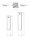
Motion·
Motion·
MARTIN LOGAN
MARTIN LOGAN
user's manual
- -
-
-
seryieing to a·quotified
Connection . . . . . . . . . . . . . . . . . . . . . . . . . . . . 4
•
Refer
Single Wire Connection . . . . . . . . . . . . . . . 5
•
tec~DJciq~ .. . ii.·•• ·•·•····•.• ·•···•·• ..
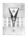
TO prevent ·fire<pr .shock.hazard,
do not exposet~·nsmodule to rnoi.sture.
Passive Bi-Amplification . . ... . . . . . . . . . . . 5
• Turn amp~ifiefoffrsh6uld ony abnormal
Active Bi-Amplification ......... . ....... 6
<
<
conditions occur.
• Do .not drivt?•speaker beyond its·rated power,
jumper Clips . . . . . . . . . . . . . . . . . . . . . . . 4
Bi-Wire Connection . . . . . . . . . . . . . . . . . . 5
Assembly and Placement ................. 6
Break In . . . . . . . . . . . . . . . . . ......... 6
Placement. . . . . . . . . . . . . . . .
.6
The lightning bolt flash with arrowhead
Toe-In . . . . . . . . . . . . . . . . . .
. ... 6
symbol, within an equilateral triangle,
Installing the Grill Covers . .... .. ........ 8
is intended to alert the user to the pres-
Solid Footing . . . . . . . . . . . . . . . . . . . . . . . 8
ence of potentially "dangerous voltage" within the
Frequently Asked Questions . . . . . . . . . . . . . . . 9
Troubleshooting . . . . . . . . . . . . . . . . . . . . . . . . 9
Contacting Customer Service . . . . . . . . . . . . . 9
General Information .................... 10
Warranty Information . . . . . . . . . . . . . . . . l 0
Serial Number. . . . . . . . . . .
. ...... l 0
Service . . . . . . . . . . . . . . .
. ...... l 0
Specifications . . . . . . . . . . . . . . . . . . . . . . . . . 11
Dimensional Drawings . . . . . . . . . . . . . . . . . 12
Martinlogan Motion 20 . . . . .......... l 2
Martinlogan Motion 42 ..... . ........ l 3
product's enclosure that may be sufficient to constitute a risk
of electric
shock.
The exclamation point within an equilateral triangle is intended to alert the
user to the presence of important operating and maintenance (servicing) instru.ctions in the
literature accompanying the appliance .
~ In accordance with the European Union
A
t3AUG2oos
WEEE (Waste Electrical and Electronic
Equipment) directive effective August 1 3,
2005, we would like to notify you that this product
Serial Number:
---------------------------
may contain regulated materials which upon disposal, according to the WEEE directive, require special
Record your serial number here for easy reference.
reuse and recycling processing. For this reason Martin
You will need this information when filling out your
Logan has arranged with our distributors in European
warranty registration. The serial number is located
Union member nations to collect and recycle this prod-
near the binding posts and on the product carton.
uct at no cost to you.
To find your local distributor please contact the dealer
from whom you purchased this product, email info@
martinlogan .com or visit the distributor locator at www.
martinlogan .com.
Please note, only this product itself falls under the
WEEE directive. When disposing of packaging and
other related shipping materials we encourage you to
recycle these items through the normal channels.
2
C€
x4
Motion 20
x2
Motion 40
3
CoNNECTION
WARNING! Turn your amplifier
off before making or breaking any
LhI
•
signal connections!
Connections are done at the signal input section
on the rear electronics panel of the speaker. Use
spade connectors for optimum contact and ease
of installation. Hand tighten the binding posts/ but
Use the best speaker cables you can. The length
do not overtighten-do not use a tool to tighten the
and type of speaker cable used in your system will
binding posts.
have an audible effect. Under no circumstance
should a wire of gauge higher (thinner) than # 16
Be consistent when connecting the speaker cables
be used. In general/ the longer the length used/ the
to the signal input terminals. Take care to assign
greater the necessity of a lower gauge/ and the
the same color cable lead to the (+) terminal on
lower the gauge/ the better the sound/ with dimin-
both the left and right channel speakers. If bass is
ishing returns setting in around #8 to# 12.
nonexistent and you cannot discern a tight/ coherent image/ you may need to reverse the (+) and
A variety of cables are available whose manufactur-
(-) leads on one speaker to bring the system into
ers claim better performance than standard heavy
proper polarity.
gauge wire. We have verified this in many cases/
and the improvements available are often more
JUMPER CLIPS
noticeable than the differences between wires of dif-
In some countries federal law prohibits
ferent gauge. The effects of cables may be masked
Martinlogan from supplying jumper clips. If none
if equipment is not of the highest quality.
are found installed under your speakers binding
posts/ please refer to /Bi-Wire Connection/ for connection instructions.
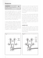
Fig. 1: Single-wire connection. One channel shown.
Fig. 2: Bi-wire connection. One channel shown.
•'
clips
installed
-«.
+
4
;
-<6-
Jumper
'-""
+
High
Jumper
clips
Frequency
Low
Frequency
00
removed
iiJ
+
SINGLE WIRE CONNECTION
the speaker, thus direct-coupling each portion of the
Please take note of the jumper clips installed
crossover to the amplifier.
under the binding posts. These clips attach the
high-frequency and low-frequency sections of the
To bi-wire you must first loosen the binding posts
crossover together. Leaving these in place, connect
and remove the jumper clips. Connect one set of
the (+) wire from your amplifier to either red (+)
wires to the upper set of binding posts which con-
binding post and the (-) wire from your amplifier to
nect to the high-frequency drivers. Then connect
either black(-) binding post (Fig. 1).
a second set of wires to the lower binding posts
clips are removed may you connect
LhI
individual runs of speaker cable
•
WARNING! Only after jumper
which connect to the low-frequency drivers. Next,
connect both sets of wires to the appropriate terminals on your amplifier. Please take care to connect
both (+) wires to the (+) amplifier terminals and both
from your amplifiers to the high-fre-
(-) wires to the (-) amplifier terminals. This is known
quency and low-frequency signal input binding
as a parallel connection (Fig . 2).
posts. Damage will occur to your amplifiers if
PASSIVE BI·AMPLIFICATION
the jumper clips are not removed.
For those that desire ultimate performance, these
BI·WIRE CONNECTION
speakers may be passively bi-amplified using the
This connection method replaces the jumper clips
existing internal passive crossover elements.
installed under the binding posts with individual runs
of speaker wire from your amplifier. This doubles
This method takes the bi-wiring concept one step
the signal carrying conductors from the amplifier to
further. You will have a dedicated channel of
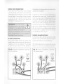
Fig. 3: Horizontal bi-amplification connection.
Fig. 4: Vertical bi-amplification connection.
One channel shown.
One channel shown.
High
~
Frequency
+
GG
Jumper
clips
removed
+
High
Jumper
clips
Frequency
removed
+
right out
5
amplification directly connected to the high- and
Connect the low-frequency amplifier to the lower
low-frequency sections of the crossover. There are
set of binding posts of both speakers. Connect the
two different methods for bi-amping with two stereo
high-frequency amplifier to the upper set of binding
amplifiers. The first and most common is referred
posts. Next, connect the left and right preamplifier
to as Horizontal Bi-amping. The second method is
outputs to the appropriate left and right inputs of
referred to as Vertical Bi-amping. With either meth-
both amplifiers (Fig. 3).
od you may use two stereo amplifiers or four mono
amplifiers, or two mono amplifiers and one stereo
Vertical Passive Bi-Amplification
amplifier. Get the idea? With either form of passive
The very nature of vertical bi-amping dictates that
bi-amplification, your preamplifier must have dual
both amplifiers be identical. With vertical bi-amp-
outputs. If your preamplifier is not so equipped, you
ing, each of the s.tereo amplifiers is dedicated to
must either purchase or construct a
"Y" adapter.
one speaker. For instance, the left channel of each
amplifier drives the low-frequency section while the
Horizontal Passive Bi-Amplification
right channel drives the high-frequency section. To
Horizontal bi-amping allows you to use two differ-
vertically bi-amp your speakers you must loosen the
ent types, models or brands of amplifiers (i.e. tubes
binding posts and remove the jumper clips from
on top, transistor on the bottom). However, we rec-
both speakers. Starting with one speaker, connect
ommend that you use two identical amplifiers (i.e.
the right channel to the lower binding posts and
same brand and model). If you must use two differ-
the left channel to the upper binding posts. Repeat
ent amplifiers, it is essential that they have the same
the same procedure for the other speaker. Connect
gain or that one of the two have adjustable gain
the left preamplifier outputs to both inputs of the left
so that you can match their gain characteristics. If
channel amplifier and the right preamplifier outputs
the amplifiers of choice do not have the same gain
to both inputs of the right channel amplifier (Fig. 4).
characteristics, then a sonic imbalance will occur.
With horizontal bi-amping, one amplifier drives the
ACTIVE BI-AMPLIFICATION
high-frequency section of the speaker while the sec-
We do not recommend active bi-amplification. The
ond amplifier drives the low-frequency section. To
internal crossover can not be bypassed. This con-
horizontally bi-amp your speakers you must loosen
nection method seriously degrades performance.
the binding posts and remove the jumper clips.
AssEMBLY AND PLACEMENT
BREAK IN
wall, you may notice improved imaging and detail
Allow approximately 72 hours of break-in at 90
if you are able to place the speakers {measured
dB (moderate listening levels) before any critical
from the tweeter and woofers)
listening.
front wall and 2 or more feet from the side walls
2-3
feet from the
(Fig. 5).
PLACEMENT
Although your speakers are designed to deliver a
TOE-IN
superb sonic performance when placed close to a
To achieve superior stereo imaging we recom-
6
7
mend that you aim them towards the primary
Fig. 6
listening position.
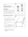
INSTALLING THE GRILL COVERS
To install this speaker's magnetic grill covers simply
move them into place (Fig. 6) .
SOLID FOOTING
With the use of the included spikes, your speakers
will be firmly planted on the floor, bass will tighten,
and imaging will become more coherent. To avoid
floor damage, do not implement the spikes until
you are secure in the positioning . The included
spikes use a standard l I 4 - 20 thread.
Spike Installation Instructions (Fig. 7):
Fig. 7
l) Carefully lay your speaker on its side.
2)
Remove existing feet or spikes. Thread new
spikes into holes and screw them in all of the
way. If the speaker does not sit level loosen
one spike until level is achieved.
3)
;fj'
Tighten the jam nut snugly by hand. Do not over
~
~
tighten the nut.
4) Right the speaker. Caution: Make sure your
hands and any cabling are clear of the spikes.
•
Do not slide speaker as spikes are sharp and
can damage your floor or carpet.
5)
Adjust to level by rotating spikes. Tighten the
jam nut securely when satisfied that speaker is
level.
Caution:
"Walking" the speaker may result
in a broken spike.
8
d
•
~
FREQUENTLY AsKED QuESTIONs
How do I clean my speakers?
Use a dust free cloth (such as a micro fiber cloth)
Will exposure to sunlight aHect the life
or performance of my speakers?
or a soft brush to remove dust from your speakers .
We recommend against placing any loudspeaker
Do not spray any kind of cleaning agent on or in
in direct sunlight. Ultraviolet (UV) rays from the sun
close proximity to the drivers.
can cause deterioration of cabinet, speaker cones,
etc. Small exposures to UV will not cause a prob-
Could you suggest a list of suitable elec·
tronics and cables ideal for MartinLogan
speakers?
lem. Filtering of UV rays through glass will greatly
reduce the negative effects.
cables quite interchangeably. We would suggest
Should I use a 4, 6, or 8 Ohm rated
amplifier with my speakers?
listening to a number of brands-and above all
All of our Motion series speakers are compatible
else-trust your ears. Dealers are always the best
with 4,
source for information when purchasing additional
receivers . Many of the most popular brands of AV
audio equipment.
receivers and amplifiers with 4, 6 and 8 Ohm out-
We have no favorites and use electronics and
6 or 8 Ohm output audio amplifiers and
put ratings have been thoroughly tested with all of
Is there likely to be any interaction
between my speakers and the televi·
sion in my A/V system?
compatibility issues except under extreme listening
Yes. These speakers are not shielded and should
purity when using our Motion series products use
be kept at least 2 feet away from a CRT television.
of an amplifier or AV receiver with either a 4 or 6
our Motion series products and we have found no
conditions. For the best performance and sonic
Ohm output is recommended!
TROUBLESHOOTING
No Output
•
Check all interconnecting cables.
•
•
If you are unable to resolve your problem,
•
Check that all system components are turned
on and source material is playing .
please contact your dealer or Martinlogan cus-
Check speaker wires and connections .
tomer service (see below).
CoNTACTING CusTOMER SERVICE
Martinlogan customer service is available
Monday-Friday between the hours of 8am-5pm
(central time) by calling (785) 7 49-0 l 3 3 or by
emailing service@martinlogan .com .
9
GENERAL INFORMATION
WARRANTY INFORMATION
SERVICE
Your speakers are provided with an automatic
Should you use your Martinlogan product in a
Limited 90 Day Warranty coverage. You have
country other than the one in which it was originally
the option, at no additional charge, to receive a
purchased, we ask that you note the following:
Limited 5 Year Warranty coverage. To obtain the
Limited 5 Year Warranty coverage you need to
1 The appointed Martinlogan distributor for any
complete and return the Certificate of Registration
given country is responsible for warranty servicing
to Martinlogan within 30 days of purchase. For
only on units distributed by or through it in that coun-
your convenience Martinlogan also offers online
try in accordance with its applicable warranty.
warranty registration at www.martinlogan.com.
2
Should a Martinlogan product require ser-
Martinlogan may not honor warranty service
vicing in a country other than the one in which
claims unless we have a completed Warranty
it was originally purchased, the end user may
Registration card on file! If you did not receive a
seek to have repairs performed by the nearest
Certificate of Registration with your new speakers
Martinlogan distributor, subject to that distribu-
you cannot be assured of having received new
tor's local servicing policies, but all cost of repairs
units. If this is the case, please contact your autho-
(parts, labor, transportation) must be borne by the
rized Martinlogan dealer.
owner of the Martinlogan product.
SERIAL NUMBER
3
The serial number is located on back of the speak-
relocate to a country other than the one in which
er, directly beneath the binding posts. The serial
you purchased yoCJr speaker, your warranty may be
number may also be found on the product carton.
transferable. Contact Martinlogan for details.
10
If, after owning your speaker for six months, you
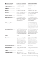
SPECIFICATIONS*
MARTINLOGAN MOTION 20
MARTINLOGAN MOTION 40
Frequency Response . . . . . . . .
46-25,000 Hz± 3 dB
40-25,000 Hz± 3 dB
Sens1tiv1ty . .............. .
90 dB@ 2.83 volts/ meter
92 dB@ 2.83 volts/ meter
Impedance . ............. .
4 Ohms. Compatible with 4, 6
or 8 Ohm rated amplifiers.
4 Ohms. Compatible with 4, 6
or 8 Ohm rated amplifiers.
1" x 1.4" (2.6cm x 3.6cm)
Folded Motion Transducer with
5.25" x 1.75" ( 13.3cm x
1" x 1.4" (2.6cm x 3.6cm)
Folded Motion Transducer with
5.25" x 1.75" ( 13.3cm x
4.4cm) diaphragm.
4.4cm) diaphragm.
Dispersion . . . . . . . . . . . . . . .
Crossover Frequency. . . . . . . .
High Frequency Driver . . . . . .
5.5" ( 14cm) aluminum cone
with cast polymer basket. Non-
Mid Frequency Driver . ..... .
resonant asymmetrical chamber
format. Rigid structured dust cap
to reduce cone break-up modes.
Two 5.5" ( 14cm) aluminum cone
with cast polymer basket. Nonresonant asymmetrical chamber
Two 6.5" ( 16.5cm) aluminum cone
with cast polymer basket. Nonresonant asymmetrical chamber
format. Rigid structured dust cap
to reduce cone break-up modes .
format. Rigid structured dust cap to
reduce cone break-up modes.
Cabinet ............... . .
Ported
Ported
Components . . . . . . . . . . . . . .
Custom air core coil and low
DCR steel laminate inductors.
Polyester film capacitors in
Custom air core coil and low
DCR steel laminate inductors.
Polyester film capacitors in
series and low DF electrolytic
capacitors in parallel. Tweeter
thermal/ current protection.
series and low DF electrolytic
capacitors in parallel. Tweeter
thermal/ current protection.
Recommended Amp Power . . .
20-200 watts
20-300 watts
Binding Post Inputs. . . . . . . . .
Custom 5-way bi-wire tool-less
binding posts
Custom 5-way bi-wi re tool-less
Weight....... ...........
371bs. ( 16.8 kg)
49 lbs. (22.2 kg)
Dimensions (HxWxD) . . . . . . .
36.6" x 6.8" x 11 .7"
(92.9cm x l7.3cm x 29.7cm)
42.5"
Low Frequency Drivers . . . . . .
binding posts
X
7.6"
X
12 .8"
( 107.9cm x l9.2cm x 32.6cm)
*Specifications are subiect to change without notice.
11
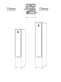
DIMENSIONAL. DRAWINGS
MARTINLOGAN MOTION 20
36.6" (92.9em)
-
33.8" (85.9em)
29.6" (75.1 em)
@@
@@
15" (38.2em)
1.1" (2.9em)
0
0
1:
""""""
~
12
~
VI
10" (25 .4em) ,..
......
11.7" (29 .7em) ,..
(17.3em)
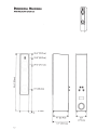
DIMENSIONAL DRAWIN GS
MARTINLOGAN MOTION 40
42.5" (1 07.9cm)
39.7" (1 00.9cm)
35.5" (90.1 em)
Eu
~
0
22.3" (56.7cm)
:::
M
@@
@@
15.4" (39.2cm)
-
1.1" (2.9cm)
0
0
1:
VI
11" (28cm)
,..
1:
7.6"
:1
(19.2cm)
12.8" (32.6cm)
13
MARTIN LOGAN®
Lawrence, Kansas , USA
P/N: 9500080
tel. 785 . 749 . 0133
telec. 785 . 749.5320
©20 12 Martin logan Ltd . Tous droits reserves .
www . martinlogan . com
Rev.#010312
NO POSTAGE
NECESSARY IF
MAILED IN THE
UNITED STATES
MARTIN LOGAN ®
BUSINE SS REPLY MAIL
FIRST-CLASS MAIL
PERMIT NO. 66 LAWRENCE, KS
POSTAGE WILL BE PAID BY ADDRESSEE
MARTIN LOGAN
2101 DELAWARE ST
LAWRENCE, KS 66046-9702
USA
1.11 ••• 11 •• 11 •••• 1•• 1.11 •• 1.1 •• 1••• 111 ••••• 1.111 ••• 1
To receive a Limited Five Year Warranty (Three Year
Warranty for subwoofers), free of charge, you must
return this registration card within 30 days from
date of delivery. For your convenience Martinlogan offers full warranty details and online warranty
registration at www.martinlogan. com. Important: Please retain your receipt. A copy of your receipt
will be required should your speaker require servicing in the future.
Importa nt!
Contact Information
Speaker Information
Name
Model(s) - - - - - - - - - - - - - - - - - -
------------------ ------------------ ------
Address
----------------- ----------------- ----
Serial #(s)
------------ ------------ --
Date of Purchase
----------------- ---------------
City _ _ _ _ _ _ _ __
Date of Delivery ______________ ______________
State _______________
Retail Store Name
Zip~--
Phone ______________ ______________ ___
E-mail
-------------- -------------- ----
0 Check here if you would like to receive occasional email
updates about news and opportunities regarding Martin logan.
----------------- ---------------
1
Salesperson S Name ----------------- -------------
How did you initially learn about Martinlogan (choose un el?
0
Internet
0
Audio magazine (please specify): _____________
0
Sales associate
0
Friend or family member
0 Other magazine (please specify): ______________
Register online at WWW1Martinlogan.com!
0 Other (please specify): ____________ ______
Rev. 060909