1
Service Manual Fault tracing
Design
Repairs
Function
Maintenance
TP 31361/1; 12.88
Section 2 (2 3)
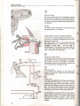
lH-Jetron ic 2.4
fuel sy stem
Engine B 230 F
240 1989-19 ..
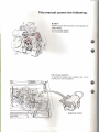
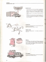
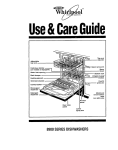
This manual covers the following: B 230 F
Gasoline engine with fuel injection and cataly tic con
erter system.
2.3 titer cylinder volume.
Two valves per cylinder.
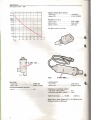
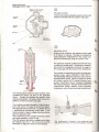
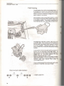
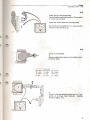
LH 2.4 fuel system
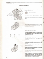
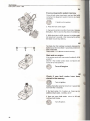
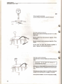
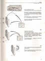
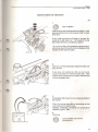
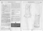
To identify the system with certainty, look for the
following item (see illustration) :
-
"
Diagnostic socket
Contents
Fuel system LH2.4 - 240
Contents
Specifications..
.. ,.,..... ... .
Special tools ..... .. .. ..
Page
....... 2 ... 5 Design and function ... 6 - System overview ........... .,. ........ .. ~ , ........ .... ,............. ..,.. ..
- Control unit ...... ,.... ..
.. ...... .._.... ........... ..... , .... ...... .. 8 - Sensors ....................................................... ,
............
.. ............ .. ........... 11 .... ......... .. ... .. .... ...........
. 13 - Catalytic converter, pressure regulator.... ......... .. ............
- Injectors, coldl start valve, fuel pumps. .......... ... ............. ................
.. ...... _.......
... 14 - Fuel filter, idle valve.
.... .. ......
.. ........ _. ......... ..._ .. .. ...... . ..... ..
15 ........ ~ ..... ......... _.... ....... ....... ...... .......
.. ...... ..._.....
.. ... 16 - System relay, fuses ..
- EVAP system....... _. . . . . . .. ........... . _ ...... , _ . . . . _ ... .. .. ............ . . .. 16 - Diagnostic system...... ........ ......
.. ........ __ ........ ........ .......... _... .............. .............. 17 Fault tracing, repairs, maintenance
Detailed table of contents ................. .
,.18
Wiring diagrams ................. ............ .......... _.... ..
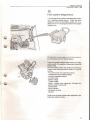
lihe first section of this manual covers the Design and
Function of the fuel system, Reading it will provide
the necessary background for understanding the
second section - Fault tracing, Repairs and Mainte
nance,
Order No.: TP 31361/1
We reserve the right to make alterations
©VOLVO NORTH AMERfCA CORPORATION
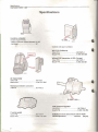
.. ..... 54 Specifica tions
Fuel system LH2.4 - 240
Specifications Gasoline, unleaded Octane requirements: - RON (Researct1 Octane Number) 91 -95 - AKI Rt M
................................ 87 2
Conlro l unit (part numbers)
Wilh EGR (California) Volvo PIN .................. ..
Bosch PIN . ..... ...... ..
.. ... 3501687-2 .. ... 0 280 000 556 Without EGR (remainder of USA, Europe) : Volvo PIN .... ............ ............... .... 3517407-7 Bosch PIN ........... ....................... 0 280 000 561 Air mass meter Volvo PIN
Bosch PIN.
.. 3517020 .. ..... ........ .... 0280212016 Resistance between connectors
. .. ............ ......... 25-4 .0
2 and 3 ...
n
0 280 160 ... Fuel pressure regulator VolVO PIN ...... ........... .............. .... 3517064-6 Bosch PIN .... .............. ............. ...... 0 280 160 294 Throttle switch Volvo PIN .. .... .......... ........ .............. 35 17068-7 .. .... ...... 0 280120 325 Bosch PIN .... ....... .. .
Syslem pressure (fuel pressure above intake
(42 psi)
manifold pressure): .. ............. 300 kPa
Specifications
Fuel svstem LH2.4 - 240
o
t
~
0580464
280 150
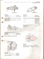
Injectors - Volvo PIN .................. .. .
- Bosch PIN ...................
. .... 3517572-8 ..... 0280150762 Injeclion capacity 214 cm'l min at 300 kPa (42 psi) system pressure. (Note : use only spedal equipment to test disas
sembled injector) Fuel pump
Volvo PIN .......... . .. .. ......... .... .. .. 1389449-8
Bosch PIN
..... .......... 0 580 464 039
Pump capaci ty al 300 kPa (42 psi) and +20°C (68 e F) :
.. .............. .. .. .... 130 liters/hour
- 12 V ..... .. ... ..
1.0 litersl 30 sec
- 11 V .. ..
.. .. 108 liters/h our
0.8litersl30 sec
.. ... .. ......... .. ....... 65 Utersthour
- 10 V
0.6 lilers/30 sec
Curren t consumption at 300 kPa (42 psi). +20· C
(68°F) and 12 V
- maximum ......... ............. .. ....... .... 6. 5 amp
Cold start valve Icertain models)
Volvo PIN ...................... ................. 3517130-5
.. ....... .... ... 0 280 170 264
Bosch PIN ....... ........
Safety screen
Injection capaci ty around 165 cmJ/min.
Fuel filter
Volvo PIN ..
.................. 1389450-6
Filters particles down to min . of: ... 0 .002 IRll
Tightening torque ...... ...... 20-35 Nm (15-25 n.I!»
Tank pump
Volvo PIN .. ............. ........... ...... ..... 1389721-0
(13 17671)
Current consumption ..................... 3-4 amp
3
Specifications
Fuel system LH2.4
240
o
40000
20000
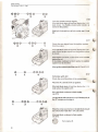
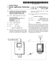
Coolant temperature sensor
- Volvo PIN. """. ""." " " ."" ,, .,,' ", 1346030-8
,, 0280130032
- Bosch PIN ,""""" '" ." ,, ' "'' ''
,
10000
8000
6000
4000
"
2000
1000
800
600
Resistance in !ls at:
-10°C (14° F) """"""
"", ,, ,, 8260- 10560
+20°C (68°F) ... " .. ' '''' '' '''
""".2280-2720
+80°C (176°F) ",,""""
"""" "",290-364
"
r-...
400
200
For other values, see chart ,
.....
r-.....
i'-..
100
-30 -20
0
20
40
60
IKt
100
120
'C
-22
32
68
104
140
176
212
248
-F
-4
l!!!2!
•"'
Q
1I~-----!!.!.
[) l' JP=.'::::::I
0258 003 ...
Idle valve
- Volvo PIN" " .. ,... " .. """."",,.,, 1389618-8
",, 0280140516
- Bosch PIN ."""",,...,,"
Resistance between terminals
Lambda-sand
- Vol vo PI N ",
"""" """ .,, "" " ,3501753-2
- Bosch PIN " " "."" " """ """ " """", 0258 003 034
1 and 2 "" " " """""" """" """"",,,. 8 n
Resistance pre-heating resistor
- cold sond. +20°C (68°F) ".".,," "" 3 n
- hot sond, over 350°C (660°F) "" ,, 13 n
Tightening torque """." " ,55 Nm
(40 IUb )
Apply "Never Seez" paste (PI N 1 161 035-9) to the
threaded section 01 the sond ,
4
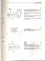
Special tools
Fuel system LH2.4
240 Special tools
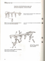
999
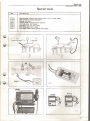
Description-use
5011-5 5116-2 5151-9 5843-1 6450-4 6525-3 9724-0 9921-0 Pressure gauge: indicating fu e l p ressure. Use d with 5 116, 5265, 5266. Ho se: connecting pressure gauge 5011.
Adaptor: CO- meter.
Vacuum pump: check ing p ressure regu lator.
Volt Amp meter : fault tracing.
Mult imeter: volt, amp , ohm. diode.
Ohm-diode meter: fault tracing.
Volvo Mono-Tester: sett ing ignition, idli ng sp eed.
~
;
~''''~Q
,
515 1 --=~~-'"
~-'<V
1"/
~~
~
CO
9724 6450
5
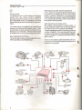
Design and Function
LH-Jetronic 2.4
~®
ltd
SV"'"
fel'Y
Iii
LH2.4
C .A
ccomp,.
A
rwlte.h
!
P"
w
I
Fuel Jystam
IIt
control
un it
[ ] 1t.Wl
~
"
Qia gnosti c
unit
Idlellll ive
@
o
Th rottle
~_W_'''_h____________~
Au
Coolant
romp_
mllill
meter
18nsor
®~'~
~
~
CIo rt.o n
~ml.'
RO."""~'17'
~\:.V
h
v....
lomb...
\ ) 'ON!
Fuol
hlt_
......
,..mp
@)
Primary
pump
®
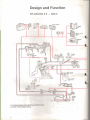
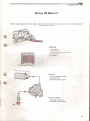
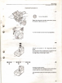
The circled numbers til the drawing reter to the same
numbers in the followin g listing,
6
/"'::\
2
\.V
Design and function
Fuel system LH2.4 - 240
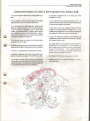
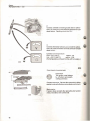
Characteristics of LH2.4 fuel system for Volvo 240:
It is used together with the EZ116K ignition sys
tem.
It requires no adjustment of CO because of the
adaptive function.
It is an adaptive system. being capable of multiple
adjustments based on driving experience .
It has a "limp home" se Ming at the idle valve In
case ofloss of current. the idle valve rem ain s open
to provide emergency air intake.
It is monitored by a self-diagnostic system that
lights up a warning lamp on the instrument panel.
It has a memory capability of up to three fault
codes (Scandinavia/USA Federal ) plus seven
teen additional codes (USA/California). Subse
quent fault tracing can be carried out by actively
utilizing the diagnostic program.
It measures intake air mass via air mass meter
supplied with a hot wire.
It utilizes a primary pump in the fuel tank and a fuel
pump with fuel filter on the fuel line to the engine .
II works on a fuel pressure of 300 kPa (42 psi) .
It utilizes a separate cold slart valve which sup
plies extra fuel at. or below 15°C (60"F) or cotder.
It provides a richer fuel mixture to counteract
knock when the fuel system's anti-knock control
system has been unsuccesslul at reducing knock
by adjusting downward several degrees .
In the USA: It has an integrated shift Indicator
refated to vehicle speed and engine rpm. The
indicator famp lights up if the rpm for the next gear
are higher than the pre-programmed limits.
-
It uses an induction sensor on the flywheet to
indicate rpm and crankshaft position via the igni
tion system control unit.
It is fitted with the same model Lambda-so nd as
for previous l H fuel systems. The resistance of
the Lambd a-sond is affected by the eXhaust-gasl
oxygen concentration
The Lambda-sond is
mounted on the exhaust manifold between tile
engine and Ihe catalytic conver1er.
It is fi tted WIth a three-way catalylJc conver1er .
It utilizes an EVAP system to handle fuel vapors
in the fuel tank .
•
7
Design and function
Fuel system L H2.4 - 240
Sell-adjusting Idle speed regu lation
Control unit
The control unit has a microproce ssor that receives
s ignal s fro m the various sensors regarding
operational conditions, evaluates them in relation to
pre-programmed valuas and calculates the correct
injector opening durations (in mil/i-seconds per revo
lution) .
The conlrol unit govern s idling rpm by regulating the
amount of aIr by-passing th e throttle valve. It also
controls other functions, such as the cold start valve,
the fuel pump and the rel ay. O ne important function
is monitoring fault fracing via th e diagnostic socket.
Self-adjusting functions
The control unit is adaptive in that it adjusts its calcu
lations according to assimilated input.
In time, wear and coatings will affect the operation of
th e throHle valve, causing less aIr to enter the intake
system . Instead 01 w orking fro m a pre- programmed
value the idle valve receives a signal that is adapted
to the experiences which the control unit has learned
from previous driving periods .
Self-adjusting Lambda-sand
The Lambda-sond operates in a similar fas hion . It
senses if the fuel mixture is rich or lean and adjusts
the control unit's Lambda regulator accordingly.
The self-regulating mechanism keeps the control unit
function at midpoint. This does away with the need
to adjust the CO content and automatically compen
sates for the effects of tolerances and wear in the in
jection system.
Whenever th e vehicle is started and driven, the con
trol unit will use the value that has been learned from
previous driving periods.
temperature
sensor
ctI;
Cold surt
L ambda
",o d
(~
.A9'J1riJ
~@ff;; ---1.~--
II
+
h
'-- -W
Ttuoule
swilt::h
~8
Ignition
control
Auxiliary
rela'y
Design and function
Fuel system LH2.4 - 240
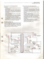
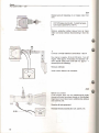
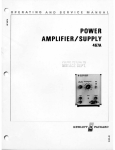
The control unit microprocessor: The control unit microprocessor
receives:
Sets the voltage of Ihe system by grounding the system relay. Breaks the sys tem relay ground if engine turns ovartoo slo wly (engine has stopped). This keeps the battery trom being drained and cuts off fuel fl ow fro m the fuel pump when the engine isn't in operation. Grounds Ihe injectors, which regulates opening, liming and injection duration. Control s air valve tor constant idle speed (CIS). Is connected to the diagnostic un it and provides fault information about the various functions. Provides the ignition system control unit with load intormation . Protects against too high rpm by shutting oH fuel injection until the engine has stowed down. USA/Canada: governs CH ECK ENG INE warning lamps and shift indicator lamp. Exhaust gas oxygen content information from the
Lambda-sand.
Rpm and crankshaft position information from the
ignition system control unit. If this information is
not forthcoming, the fuel system control unit will
not function.
Engine temperature information from the coolant
temperature sensor.
Engine load information from the air mass meter.
Information from the shutter switch as to whether
the throttle shutter is closed or wide open.
Electrical system voltage from the battery current.
The signal from the AC switch inform s if it is on,
and the signal from the compressor connection
indicates that the compressor is operating.
Emergency program
There is a "limp home" function provided if the signal
from the air mass meter ceases for some reas on,
such as the hot wi re burning off. A pre-programmed
value is used fo r Injection duration, allowing the
vehicle to be driven slowly to the garage.
r-----------------------------------------4 .
r:':· lJ
r------;:;:;:=~===
~~:~m8612
0 ..".-----'~,
IL-_ _ _ _ _ _ __
"'12 _ - - ,
31 / 1"'--
1
20 I
~ --e lZ
~ _ ';;~="=-=='-:=!.~
-I =-O}o
•
L._ _ Cr&nksh!tfl posit ion _
Shift indicator
n
L...I
_
S,m.,/so
Cold start
~ @",/:." ,
,
",..
.
-------e
24
f
t
; ....
6 .
2ti I
r
.
10 • 11
31 1
12
~
113 •
, 321::: :
• 331,1 16
Ignition 5Y5tem
control unit
Throttlll switch
1
..r=..
(\'¥-,--- ,
, \.?__
8 I
30 1
0
.....
~
• 2
• 3
25 1 7 '
• 21 1 9 ~
~. ~
I die waive
5 •
enflchm6"' ~
V
~¥
~~
I
4 ~~::
Knock
41'"_ ........"'Sattery +
. . . . • 23 11 ~KIJ !....I
=-r-,-d,-.-""""L..JRpm - - -
3 "'-- Full load - - .
21 1
~
K-
L -_
~
!Ir-------- 15 I
•
Ai r mati
meter
b
"
1
' -
.
4
5
-
' _I,~'I
Diagnotti,
un't
~
... "'. .
-
'
----" .~
AC <omp""'o,
r=;':":'t 'W~::::'.:.:h: ::'1
AC
'
I,
::..:
Coolant
tem peratu rlr
sensor
,.
':
:r~
._
\\
~\.---+\---+-,
r- :,117 :J ~~"'~
'E-x.,,\.~,
118
k.::......
---....: -~
-
9
Design and function
Fuel system LH2.4 - 240
Th e start-up program provides for two injection durations per revolution. The cold-start valve is activated when the tem
perature is at -15°C (5°F) or below, and the engine speed is under approximately 900 rpm. Once the rpm exceed the pre-programmed limit, the cold
start valve Is turned off. The choke provides a richer fuel mi xture to the
engine up to an engine tempe rature of 60°C
(140"F).
Injection duration increases during acceleration.
======> '"
~ ------------
During normal driving conditions, injection dura
tion is regulated mostl y with referen ce to signals
trom the air mass meter.
At full load, a richer airlluel mixture is used to
provide maximum engi ne power and to lessen the
el1ects of combustion heat on the engine and the
catalytic converter.
10
Knock enrichment provides a richer fuel mixture
to cou nteract kn ock when the fuel system's anti
knock control system has been unsuccessful at
reducing knock by adjusting downward severat
degrees on all cylinders. Knock cause high
combustion temperatures. When knock occurs,
the control unit increases the amount of fuel in
order bring the combus tion temperature down
and reduce the knock.
Excess rpm is prevented via a rotation speed
limiter which turns 011 the injectors. They are
turned on again when the engine rotation is re
du ced.
During deceleration, fuel injection is discontin
ued above 1,800 rpm in all gears. It is resumed at
1,400 to 2,000 rpm, depending on engine tem
perature.
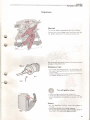
Design and function
Fuel system I.H2.4 - 240
Air mass meter
Measures engine inlake air mass. Those factors
which affect air density , such as temp rature, humid·
ity and ptessute (altitude) elc. are laken inlo consId
eration during measurement .
The measurement sensor insi de Ihe air mass meter
consists of a wire which Is maintained at 12.0"C
(2.S0DF) (previously IOO"C -(215'F ) higher tllan tile
ambient air entering the engine. As the air mass
passing over the wire increases. more currenl is
required to maintain the correct temperature. The
amount of current required Is used to catculate the air
mass taken In.
When the engine is turned oN, any dirt on the wire is
burned oN electrically by heating the wire to over
1000' C (tBOO' F). Any dirt remaining on the wire
would cause it to send incorrect information to the
control unit and result In an Incorrect fueUair mixture.
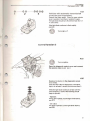
Protect ive
grille
Earlier models of the air mass meter were provided
wi1h an adjustment screw for CO seNings. However.
because the LH2..4 Lambda-sand is self-adjusting
this screw is no longer necessary.
o
Coolant temperature sensor Provides the control unit with information regarding the engine temperature necessary for proper adjust
ment of injection duration. 11
Design and function
Fuel system LH2. 4 - 240
Obt009 mount!", bol.- tor
adjun ino Iwheh Mtting
o
Throttle switch
Tells the fuel system and ignition system control units
whether the throttle valve is closed or fully open.
Fuiliolid
switch
~
Throttle
spindle
__
--~~-"i~r&2])IS
C.m disc
Idle switch
(micro SWiTCh)
o
Lambda-sond
Under normal conditions, the optimum mixture ratio
is 14.7kg air to 1kg fuel. The ratio is monitored by
post-combustion measurement of the oxygen con
tent in the exhaust gas using the Lambda-sond.
This particular model of Lambda-sond is known as a
"comparing Lambda-sond'. It produces a measure
able current by comparing the amount of oxygen in
the exhaust gas with the amount in the ambient air.
Heatin':..-.Jt...-H
n.m
Sensor
The Larnbda-sondoperates only within a certaintem
perature range - approx . 285-850°C, (545-1530°F).
It is electrically heated to enable it to reach operat
ing temperature quickly . When the ignition is turned
on, current is sent to a PTC resistor (Positive Tem
perature Coefficient) whose resistance increases
with rising temperature. Because of this system, the
Lambda-sond quickly reaches correct operating
temperature, even at low exhaust gas temperatures.
=
The exhaust gases reach the outer surface of the
Lambda"sond sensor via slits in the protective
sleeve . Ambient air reaches the sensor's inner
surface via channels. The sensor itself consists of a
pfatinum covered zirconium-oxide pipe.
The Lambda-sond signal strength is in direcf propor
tion to the amount of oxygen in the exhaust gases.
This depends on the airlfuel ratio. A Lambda value of
1 represents the theoretically perfect ratio. A rich
mixture results in a higher voltage and a lean mixture
gives the opposite result.
The current sent by the Lambda-sond to the control
unit varies between 0.1 and 1.0 volt .
The shift between high and low voltage occurs when
the Lambda value is at 1. The control unit uses this
information to adjust the amount of fuel injected.
12
The Lambda·sond is mounted in th e exhaust gas mani
fold about 15 cm (6 in.) in front of the catalytic co nverter.
Design and function
Fuel sys tem LH2.4 - 240
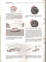
Catalytic converter
In order to be able to operate as inte nd ed, th e
catalytic converter is dependent on correct informa
tion from the Lambda-sand. The air/fu el mixture must
be adjusted so that fuel is completely burned in the
engine prior to the exhaust gases reaching the cata
lytic converter.
The converter can be damaged through overh eating
if unburnt fuel is emitted in the exhaust where oxygen
is present.
This can happen if a large amount of unburnt fuel
reaches the catalytic converter prior to starting . It can
also happen if there is a loose ignition cable, and a
cylinder pumps unburned fuel into the exhaust.
The catatytic converter cleans the exhaust gases in
three ways :
1 - by incinerating unburned hydrocarbons (HC) at
high temperature, releasing the residue as
steam (H,O).
2 - by converting carbon oxide (CO) to carbon diox
ide (CO,) through oxidation.
3 - by reducing nitrogen oxides (NO,) to gaseous
nitrogen (N).
90 to 95% of the dangerous gases are rendered
hamnless.
Lead in the fuel will quickly aHect the Lambda-sond
and cause the exhaust gas cleaning function to stop
working. If tllis happens , the Lambda-sond will stop
providing the information needed by the con trol unit
to set the fuel mixture and the cataly~c oonverterw ill
then be destroyed.
The active area is about 20,000 sq. m (2 15.000 sq.
ft .) . (California EGR converter approx, 32.000 sq. m
~ 345,000 sq, fl.) The precious metal content is about
2 grams (.07 oz) of platinumlrhodlum,
®
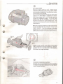
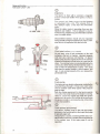
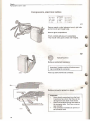
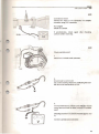
Fuel pressure regulator
o
Di stribution pipe
Theincoming fuel feed line, pressure regulator, injec
tors and cold start valve are connected to the distri
bution pipe.
The fuel pressure regulator ensures that the fuel
pressure remain s constant at the Injectors . Using a
vacuum tube connected to the eng ine Intake man i
fold, the fuel pressure is kept at 300kPa (42 psi)
above (below) the intake manifold pressure . In this
way the pressure over the injectors is kepi constant,
regardless of throttle pOSition . The amount of fuel
injected depends entirely on the Injection duration.
Excess fuel is returned to the fuel lank via a return
pipe.
(
13
Design and function
Fuel system LH2.4 - 240
o
Injectors
o
The injector is fin ed with a solenoid, a magnetic
actuator and a fuel needte which opens or shuts a
nozzle.
The control un it feeds current to the injectors
in ca lculated time units. This ensures that all
the injectors spray a fine fuel mist simultane ·
ously .
While the starter motor is opem ting, there are two
injeclions per rotalion. This is redu ced to one for
normal dri~ i ng. Injection occurs in the intake manifold
near the intake ~alves.
280 150 ... Disa ssembled injectors should only be inspected
using specially designed equipment in order to mini
mize the risk of explosion from fhe fu el mist.
..
Cold start valve
(eenail! models)
At cold start, a lot 01 fuel condenses on the cold
surfaces in the lorm of droplels . Having a separate
cold start valve improves cold starting. It's placed
farther away from the engine block than the ordinary
injectors and delivers the fuel more as a gas Ihan as
drops. The cold slart valve is controlled directly by the
conlrol unit, ralher than by the thermal time swifCh . It
culS in when the temperature is aboul -15c C (5°F)
and when Ihe engine rolation is below approx. 900
rpm. It culs out permanently if the rpm exceed the
permissible limit.
Vi!llve
®
Fuel pump
The fuel pump is an eleclric roller pump , cooled by the
fuel which flows through it. It has a non-return valve
and an overflow valve which opens if the pressure
gels 100 high .
Both the primary pump and Ihe fuel pump operate
when either the starter motor or Ihe engine is running .
However, should the engine stop while Ihe ignition
remains on , the conlrol unll wi ll cut off the current to
the pumps in order 10 eliminate Ihe risk of fire in Ihe
even! of an accidenl.
pump
Tank
pump
@
Tank pump (pre-pump)
The electric Impeller pump in the fuel tank keeps
pressure in the fuel lTne prior to the (main) fuel pump
to prevenl vapor lock.
The pump has a coarse, slralner Iype filter and a non
return valve to maintain a certain amounl of pressure
in the system even if the main pump is not in
operation .
14
Des;gn and funct;ol].
Fuel sys tem LH2.4 - 240
Safety scre8n
@
Fuel filter
The luel filter is adjaoentto the fuel pump and both are
mounted on a plate below the veh icle under the back
seat.
Itconsists of a paper filter and asafety screen to catch
any pieces of the paper filter which come loose .
Idle valve
,In order to set the correct air valve opening and thus
achieve constant idte speed , the control unit uses in
formation from the air mass meter regarding the
amount of air entering the engine and from the
ignition system control unit regarding rpm. This
means that the idle valve is not affected by air leaks
or a jammed throttle valve.
When the current is off, a spnng sets the idle valve
opening for an idle speed between 1.000 and 1,100
rpm .
Once the engine is running, the control uni t ensures
that the idle valve is more or less open al all rotation
speeds in order to prevent the development of unnec
essarily high negative pressure in the intake manifofd
when the throttle shutter closes suddenly during
deceleration.
The control unit receives a signal from the AC control
when the AC is tumed on or off to enable it to adjust
the idle valve. Signals are also sent to the control unit
from the AC compressor so that the idle valve can be
adjusted each time the compressor turns on or off .
..
When the throNle valve switch is closed during idling,
the control unit receives a signal, enabling it to send
current to the air valve electric motor to keep the idle
rpm at the correct level.
There is no signal to the control unit when the shuNer
switch is open. When driving , the control unit keeps
the idle valve partially open so that the negalive
pressure in the intake manifold is reduced when the
gas pedal is released .
15
Design and function
Fuel system L H2.4 - 240
System relay
Governed by the control unit , it provides current to
the fuel pump, the injectors, the cold start valve, the
air mass meter and to certain control unit functions .
The system relay and its functions are protected by a
20 amp fuse.
Fuses
The system relay is protected by a 25 amp fuse and
the tank pump by a 15 amp fuse .
Ignition system
contol unil
Evaporative Control System (EVAP)
This system handles the gases that result Irom nor
mal fuel lank evaporation, keeping Ihem from escap
ing and pollu1ing the air.
Via a hose system , the luel vapor passes from the
filler opening through a roll-over valve to a reservoir
("canister', "carbon IIfter-). The fuel vapor is
absorbed here. n 1e reservoir is provided with an
EVAP valve which prevents leakage of fuel vapor
while the en gine is not in operaHon.
SYl tem relay
FUIII system
co ntrol unit
®
iQ:::='J
~~/
~Stl,-===
fJ
Reservoir (carbon IIIter) The fu el vapors from the fue l tank enter the top of the active carbon filter and are absorbed. Air is pushed out through a channel in the bottom of the filter. Depending on temperature and other conditions , the filter can bind approx . 90 grams of fuel. ®
Roll-over valve
If the vehicle leans sideways at more than a 45'
I)
.
angle, this valve closes , helping to prevent fuel spills
during accidents.
Carbon
fihM
@)
EV AP val ve
This valve is located at the top of the carbon filter and
is closed when the engine is turned off. It's also
closed during idling in order not to interfere with the
automatic idle settings or make the fuel mi xture too
rich. The valve is closed using vacuum pressure
taken Irom the intake manifold and through being
connected to the throttle shutter positive terminal.
Increased engine load opens the EVAP valve , allow
ing fuel vapor to flow from the carbon filter into the
engine intake manifold . Air is drawn in at the same
time through the bottom channel. Under normal
conditions , the filter is emptied of fu el in 15 to 20
minutes .
16
Design and function
Fuel system LH2.4 - 240
®
Fuel system diagnostics
The fuel system has a built-in self-diagnostic system
and a funclions testing system _ It uses the same
diagnostic socket as the ignition system and Is lo
cated behind the Ie" spring strut tower in the engine
compartment.
The diagnostic system uses socket 2 for the fuel sys
tem and socket 6 for the ignition system. There are eighteen different fault codes in the diag
nostic system. It is capable of storing up to three fuel system faults. The fuel system control unit carries out continuous checks of the following functions while the engine is running: - The control unit's own internal functions . - Lambda-sond and Lambda settings. - Coolant temperature sensor. - Air mass meter. - Battery voltage. - Throttle shutter. - Ignition settings and engine rpm (through Ihe ignition system control unit).
- Speedometer.
- Knock indicator.
- Idle speed air valve.
- Injectors.
Faults in any of these funclions are registered in the
diagnostic system memory .
17
The Design and Function 01 the luel system has been
described on the preceding pages. II is important to read
them il you are to have a dear understanding 01 the next
section.
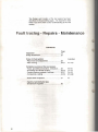
Fault tracing - Repa irs - Maintenance
CONTENTS
Page
Important! ........ .
Group 20 General ...... .
Function
Group 23 Fuel system
• Placement of components ......... .. .............. .. 22
• Fault tracIng ......... .. .... ......
...... .. .. 24·31
AI ·A 15
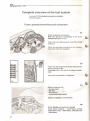
Complete overview 01 the luel system .
- Fuses, grounding connections, connectors ..... 32
· Air leakage and throttle shutters .......... ............ 33-34
• Pumps, pressure regulator, fuel lines ....... ....... 35·37
· Components, cabling.
.. .............
.. ... 38·50
81 -84
Cl·C6
Dl·D6
E l-E28
· Quick check of injectors
Fl
• Injectors, luel distribution pipe
and pressure regulator .... ...... .
18
........ _ . .. ... ....... 19
..... _... .... ........ 21
... 51
. ......... ........ 52
Important
Fuel system LH2.4 - 240
Important
Wa rni ng! The ignitio n syst em o perates at ve ry high voltages. Extreme tare must be taken when working On th o igni
tio n system, even w hen removi ng connectors etc. Th e foll owing ins tru ct ions mus t be followed to prevent
damage to the con tro l u nit.
Compress ion test:
- dtsconnect w ire from terminal 1 on tho Ignition cOil
(to prev ent arcing affecti ng tho olOCHIcal system's
control units}
- remove co nnectors from injectors (to aVOId flooding
the en gine. ddUTlon of 0 11 etc )
(
Tu rn off ignition when:
- connecung/ dlsconnectlng les equlpm nt
- connec tmg/ dlsconneCl ing conuol unit connector
- connecllng/ d lsconnoctlng leads to Ign1llon cotl and
plug
Banery:
- do not disc onnect battery w hon the engine IS
runmng
- djseonn c baH ary when boost cha rging
- do nor use boost chargers wi th a voltage ra ting of
m ore than 1SV when Jump starting engine .
19
Important
Fuel system LH2.4 - 240
Control unit:
- remov e con trol IJnI I when the ve hicle is p.xp osed to
high temperaLU r s for exampl e hea t trealmeniS for
baking on paln1. The con trol unll m ust not b e ex~
po sed to a t em peraturo In excess of 80 '" C (176 F)
- dlsconnecl con tro l unit whf!n carrying o ut wel ding
ro palrs
- remove cont rol unll jf w eldin g I S to b e ca rn ed out
near Ii
- do no t Insen a ne w control unll wit hout haVing firs t
checked all wIring and cornponenls Otherwis e a
faul! c an d<lmage the ne w control unit in th e same
way as the old.
U
Cl eanliness
The utmost cleanli nes s must be obs erved when
In9 with tho fuel system
Cl ean all con ne ct io ns before remo val
work ~
Gasket, seals
Insta ll new gasket /se al
loosened.
If
a fu el pIpe c onnec tio n
IS
Battery
I[ is imp ortant w nen te s ti ng th e di ffere nt components
to ensure that the batt ery volt age IS w ithin s pecif l ca ~
tlon s. If necess ary , a ba tt ery charg er can b e connected
dUring te s tin g M ax. c harging curre nt: 15 A at m ax .
cha rging vo hage o f 1 6 V.
Fire hazard
Extreme care sh ould be taken to avoid cau sing sparks,
especi ally when tes ting injectors
20
G.ntlrs/
Fuel svstem LH2.4 - 240
Group 20 General
Wh en tracing en gine malfunc tions alw ays perform the following checks b e fo re carr ying out any fa ult diagnosis o f
the LH-Jetronic sys tem :
•
Mechanical
.... /._......
' ."
•,
(-----
it
'/
...... .•.,..
w..
"
: .1 -,1 .
,
-
compres si on
valve clearance
vacuum hoses ana connections
throUle control
- air clean e r
Electri ca l
- sp ark pl ugs an d HT lead s
di stri but o r cap
- ali el ectr ical 'connect ions
Em ission controls
- crankcas e ve ntilation
- evapora te c ont rol sys tem
21
Group 23 Fuel system Function
Page
......Al -A15
22
24-31
Complete overview of the fuel system ,
- Fuses, gro unding connectio ns, connectors .. ... 81 -84
- Air leakage and throHle shut1ers
... . G l-G6
- Pumps , pressure regulator, fuel Rnes
..... 0 1-06
- Components, cabling ...
...... E l -E28
32
33-34
35-37
38-50
Quick check of injectors ........ " ........ . ............ .. Fl
51 Injectors, fuel dislribution pipe
and pressure regulator ....................... .
52
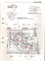
Placement 01 components .......... .... ..
Fault tracing .... ..... ... .... ...
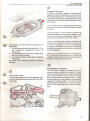
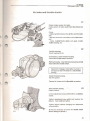
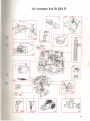
Placement of components
Ignition syste m
lI:onlol
unlt
Th e Lam bda-sond is mounted in the exhaust gas man i
fo ld ab out 15 cm (Sin .) in front of the ca talyti c conver ter .
System reley
Fuel synem
control unit
The fuel syslem control unit and system relay and !he
tgnition syslem control unit are located inside the
panel In front of the right door plOar.
22
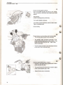
P/8Cllmenr Df components
Fuel sys tem LH2.4 - 240
Tank pump
Tank pump (pre-pump):
Inside fuel tank (Iuel level sensor section).
Fuel pump and fuel filler:
On a shelf below the vehicle. under the backseat.
Co ld ttart
Fuel d istribution
pipe
Thr o ttle
switch
Prusur.
ragulator
•
.--/'
te mperature
,.nsor
Idle'lilve
Airmass
met....
EG R
(Ca llf o rni. )
23 Fuel system LH2.4 - 240
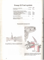
Fault tracing
The fuel syslem has a built-In fault tracing system. It
is mounted In the control unit and has three dillerent
control functions, one 10 read fault codes stored in the
memory and two for continuous testing of the compo
nents included in the system.
Communication with the diagnostic system is carried
out through the dlagnos licsocket , (which is also used
by the ignition system) . The socket is located behind
the left spring strut tower In the engine compar1ment.
The diagnostic socket has a button, a light diode and
a selector cable. When carrying out tault tracing tor
the fuel system, the selector cable is placed in socket
2 of Ihe 6 available , Depressing the button once,
twice or three times chooses the desired fault trating
function.
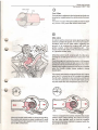
Faults stored in IIle memory are read via a system of
flashes from the diagnostic socket light diode. All
lault codes have three numbers, each one capable of
ranging trom 1-9. The codes relating to the luel
system range only between 1 and 4.
The fault code figure is read tram the series at nashes
delivered by the diode. Since the codes all have three
numbers, each code requires three series of
uninterrupted flashes.
There is a three second interval between each series
of flashes to make the code s easy to read .
Here Is a fault code example:
=fault code 213
24
Fault tracing
Fuel sysrem LH2.4 - 240
Control function 1
The diagnostic system carries out continuous ctlecks
of the fuel system during engine operation.
Any fuet system fau lts are stored in the diagnostic
system's memory as a fault code. The system can
identify and store seventeen different fa ult codes.
There is also a code to indicate that the fuel system
is co mpletely OK.
,
Up to three fault codes can be stored in the memory
simultaneo usly .
Once the engine stops, the fault codes can be read by
counting the flash series at the diagnostic socket
diode.
Control function 2
This tunction tests the various fuel system breakers .
As each one is activ ted. functions information is
provided by the diagnostic socket diode in the form of
ftash series.
The functions test is generally used aHer such activi
ties as repairs to check that certain controls are
connected and operating correctly .
•
Control function 3
This test is carried with the engine off . It tes ts the
adjustment functions of the fuel system.
In this case, the test consists of initiating an functions
cycle whereby the diagnostic system activates cer
tain control components .
You find out if the component is operating correctly
either by placing YOtI, hand on the component or by
listening for the click which occurs when the compo
nent is activated.
25
Fault tracing
Fuel system LH2.4 - 240
Control function 1
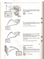
A1 Open the diagnostic socket cover and connect the
selector cable to pin no .2.
Turn on the ignition.
Enter control system 1 by depressing the button
once.
Depress the button lor at least 1 second, but not more
than 3.
Watch t~e light diode and count the number of flashes
in the three flash serie s indicating a lault code. The
flash series are separated by a three second interval,
making them easy to read.
Make a note 01 the fault codes.
t:t --0= - - 0= 1
1
1
If no fault codes are received by the diagnostic
unit, the diode will flash 1-1-1 and the luel system
is operating correctly.
Continue at A7.
II the light diode doesn't flash when the button is de
pressed or il no code is flashed, reler 1081-82, El
E4 and Ell.
A2
Check to see if any lault codes are stored in the
memory.
Depress the button again .
additional lault codes.
Make a note 01 any
Depress the button a third time to see if a third ·fault
code is stored in the memory .
If the code received when the button was depressed
the first time is repeated, there are no other codes in
the memory.
NOTE! The diagnostic system memory is lull when
it contains three fault codes. Unlil those three are
rectified and the memory is erased, the system can
not give inlormation on any other problems.
26
Fault tracing
Fuel system LH2.4 240
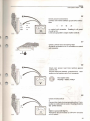
A3
The fault code key below shows the fault indication codes. Information on how to corre ct the faults is in the third col
umn.
Fault code key
1-1-1 No faults
1-1-2 Fault in control unit
Change control unit
1- 1-3 Fault in injector (Break in lead. clogged. etc.)
E17, 01-5, Fl
1-2 -1 Signal to/from air mass me ter is faulty
1-2-3 Signal missing tolfrom coolant temperature sensor, possi ble grounding short
1-3-1 Ignition system rpm SlgnaJ missing
E10, E27
E14
E6
1-3-2 BaHery potential
too low or leo high
Check battery
and charging system
1-3-3 TI1rottleswitch; Idle setting faulty, possible grounding short
2-1-2 Lambda-sand signal mi. ing or is faulty
C4, E9
E12, E2S-27
2-1 -3 Throttleswitch; full load setting faufty. possible groundlllg short
2-2-1 Lambda-sond not operating
2-2-3 Signal missing tol trol'l'l KlIe valve
C4,E9
C1,Ol-5
E20
2-3 - 1 Self-adjusting Lambda-sand not operating
2-3-2 Sell-adjusting Lambda-sand not operating
2-3-3 Idle valve closed. possibly leaking air
C1 , 01-5
C1 , 01-5
C1, E20
3-1-1 Signal missing from speedometer
3-1 -2 Signal missing for knock related fuel enrichment
3-2-2 Burn-off cleaning of hot wire in air mass meter not operating
E21
E19
E27
•
27
Fault tracing
Fuel sy.tem LH2.4 - 240
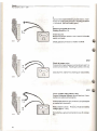
A4
Erasing diagnostic system memory
Once all fault codes have been read and the faults
corrected , the diagnostic system memory is erased
as follows :
@
1. Switch on the ignition.
2. Read the fault codes again .
3. Depress the button more than 5 seconds. Release
the button. After 3 seconds the diode should light up .
4. While the diode is still lit: depress the button again
for more than 5 seconds. After releasing the button
the diode should stop shining .
A5
~ -- C:--C:
1
1
1
To check that the memory is erased, depress the button once for more than 1 second but not more than 3 seconds. Flash series 1-1-1 denotes erased memory. Start and run engine If the engine won't start, see control function 2, A 7-8 and All . (NOTE! The throttle control does not have to be turned to full load position .) Turn off engine
A6
Check if new fault codes have been
stored in the memory
@
Turn on ignition.
Depress the button once for more than 1 second but
not more than 3 seconds.
If the flash series 1-1-1 comes up, there are no
additional fault codes. Continue at A7.
If there are more fault codes, retum to A2 and
continue fault traCing.
Turn off ignition.
28
Fault tracing
Fuel system LH2.4 - 240
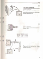
Control function 2
•
Al
Turn on the ignition_
Open the diagnostic socket cover and connect
the selector cable to pin no. 2.
Turn the throllie control to full load position .
A8
Depress the bullon in the diagnostic socket twice. Each time the button is depressed. it should be kept in for at least 1 second, but not more than 3, The lighl diode should begin to flash. fJ: C: C: -
- fJ: n n -
-0: no:
A9
333
Release throttle control
II the flash series 3·3·3 comes up, the function of the
shutter switch is correct in full load position.
lithe light diode continues to flash rapidly. see C4 and
E9,
29
Fault tracing
Fuel system LH2.4 - 240
:(tc=c=-- c=nc=--c=n 3
3
2
Al0
Turn the throttle control slightly
If the light diode turns off and then flashes the 3-3·2
code series, the throttle shutter switch function is
correct in Idle position.
II the light diode con tinues to flash rapidly, see C4 and
E9.
A11
n ~n-- ~nn--n
331
Check the rpm signal from the fgnltlon system Start the engine. If Ihe fight diode turns off and then Dashes the 3' 3- 1 code seri es. Ihe rpm signal from Ihe ignition system is corre ct, II the engine won't sta rt, run the starter molO( until the diode turns off. II the diode continues to flash rapidly the ignition system must be checked. If the ignition system is faultfree, see A 13 and E1 -12 , A12
Vehicles with AC
Check the onloff funcllon of the compressor
Place the AC controls in the on position,
If the light diode turns off an d then " ashes the ' · 1·4
code series, the switch is OK.
II the light diode continues to flash rapidly,
see E16.
n --nn n --c= n n n 1
3
The light diode will now retum to rapid fl ashes prior to
the AC compressor turning on.
4
When the compressor turns on, the light diode should
turn off and then flash the 1-3-4 code series,
If the light diode continues to flash rapidly,
see E15.
Turn engine off.
30
Fault tracing
Fuel svstem LH2.4 - 240
.0 1
- 0
(I: - -(I: C (I: C
2
4
A13
Vehicles with automati c transmissi on
(Testing idte speed compensation.) Depress the brake pedal. Ptace the gear setector tever in position D and then in position N again. The light diode should turn off and tllen flash the 1-2
4 code seri es. II the light diode continues to flash rapidly, see E22_ Turn engine olf.
Control function 3
A14 Turn on ignition.
Open the diagnostic socket cover and connect
the selector cable 10 pi n no. 2.
A15
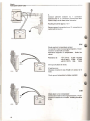
Dep re ss the button In the diagnostic socket three Urnes. Each time ttle button is depressed, it should be kept in for at least 1 second, but not more than 3. While the light diode continues to flash with the same frequency , each of the tollowing should hegin to operate: - Injectors If they don't operate, but the lighl diode flashes , see E17 . - Idle valve If it doesn't operate, but the light diode flash es, seeE20. 31
Fuses
Fuel system L H2.4 - 240
Complete overview of the fuel system
Functions Bl -E28 constitute acomplete examination
01 Ihe IUllI system.
Fuses, ground connections and connectors
B1
Check all ground connections
Make sure tile ground connections on the intake
manifold make good contact
Poor contact can b e th e cause of many diHerent fault
symptoms.
Check the grounding connection lor I.h e lambda
sond althe right Iront mudguard.
B2
~
iJ
1!14
IJ
IJ
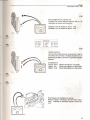
Check Ihat the luses for the pump relay and the
primary pump are OK
Pump relay fuse: In-line fuse In !he engine comp art
ment
Tank pump fuse: fuse No. 4 in luse box.
0
m:m
B3
Check connectors lOt:
- air mass meter
- idle valve
- knock sensor
- coolant temperature sensor
Check for installation and connection.
B4
Check that the connectors are correct
Knock sensor connector = black sleeve; Coolant
lemperature sensor = white sleeve; Cold start valve
= blue sleeve.
32
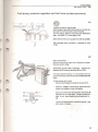
Ajr l eakage
Fuel system LH2.4 - 240
Air leaks and throttle shutter
Cf
Check Intake system lor leaks Intake sy stem air teak s would make the mixture too lean. Check : - Intake manllold between the air filter and Ihe m ani
fold. - All hoses and hose connecllons to the intake manl
lold. - Intake manifold bolted joints and seals, throttle sh utter housing, etc. C2
Throttle housing
Check housing for dirt.
II necessary, clean throttle housi ng
Disconnect throttle switch connector.
Remove housing. Clean with solvent, but ensure that
none enters th e throttle switch.
Important! A clogged, incorrectly mounted or
damaged air filler will result in a dirty throttle
housing.
Install throttle housing
Use new gasket.
Connect air hoses and throWe swilch connector.
Basic throtlle selling
Loosen locknut.
C3
Loosen adjuslment screw until throttle Is oompletely
closed.
Tighten adjustment screw until It lust touches the
linkarrn. Turn a hall turn further.
Tighien locknut withou t changing the adjustment
screw position.
(It may be necessary to loosen the throttle switch
before setting the throtUe.)
33
Air leakage
Fue/ system LH2.4
240
C4
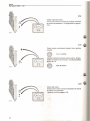
Check throttle switch setting Open the throttle slightly and listen to the switch. There should be a click when Ihe shutter opens (idle switch) . Adjustment: Loosen mounting bolts (3 mm hex.) Turn switch stightly clockwise. Turn switch counter-ctockwise untit the switch clicks. nghten mounting bolts. Check setting . C5
Ch eckladjusl control pulley and ttuoltle cable
The control pulley should move smoothly.
The throttle cable should be extended in idle
position without affecting the pulley position. The
pulley should abut the idle stop . Adjust cable
where necessary.
Depress gas peda l all the way and check that the
pulley abuts the full throttle stop.
C6
Connect and check/adjust lInkarm
Install a 1 mm leeler gauge between the control
pulley and the idle stop.
The play between the throttle lever and the adjust
ment screw should O.2-+{).1 mm .
Adjust link arm where necessary .
34
System pressure
Fuel system LH2.4 - 240
Fuel pump, pressure regulator and fuel lines (system pressure)
D1 Connect pressure gauge 5011
Hold a paper towel under the fuel line to absorb any
fuel spill when the fuel line is disconnected.
Connect gauge between fuel line and distribution
pipe. Use hose 5116 and nipple 5265.
Block the free end of the gauge hose with plug 5266.
Set the gauge cock in position 1 (pointing to hose
511 6) .
D2
Start fuel pumps Remove panel under ri ght side of instrument panel. Remove system relay. Disconnect syslem relay connector. Connect an eleclrical lead between terminals 30 and 87/2. The fuel pumps should start. To check if the main luel pump is operating, remove cap from the filler pipe and listen. II fuel pumps don'I start
Remove lead between tenninals 30 and 87/2.
Ched< for voltage atlermlnal3O. Iflhere is none,
check lead between relay and battery .
Connect an electrical lead between terminals 30
and 87/2 on Ihe relay base . Pumps should now
start. If nol, check lead between pump and re
lay.
" 30
I '~.IIII,J
85
Check lead between 87/1 and 85 for breaks . Use
ohm meIer or buzzer.
35
SYS ~m
pressure
Fuel system LH2.4 - 240
D3
Chll(:k sYStem pressure System pressure should be 300 kPa (42 psi). 1
Too high system pressure: Remove lead between terminals 30 and 8712 on the relay base. Remove retum hose from pressure regulator. Blow
in the pipe.
Remove vacuum hose from pressure regulator. Blow
in pipe
If both hoses are open, the pressure regulator is
faulty . Replace it and recheck pressure .
...
Too low system pressure :
Squeeze relurn hose by hand and check if pressure
rises .
Important ! Do not allow the pressure to
exceed 600 kPa (84 psi) .
If the pressure rises rapidly the pump and ,hoses are
OK. Replace pressure regulator and recheck pres
sure.
If the pressure rises slowly, the fuel filter, fuel pump
strainer or the fuel lines are dogged or blocked.
If the pressure doesn 't rise the fuel pump is faulty.
36
System pressure
Fuel system U/2.4 - 240
D4
Check fu ncllon of pressure regulafor Connect a vacuum pump to the pressure regulator . Vacuum pump 5843 may be used. Pump air Irom the regulator and check that system pressure falls. The system pressure should lall as much as the pressure in the regulator lalls. • 300 kPa (42 psi) minus pressure drop equals
system pressure.
86 / 1
87 / 2
D5
Turn oU fuel pumps
Remove lead bAtween terminals 30 and 8712 on the
relay base. Install system relay.
D6 Remove pressure meter 50' , Hold a paper under the luel line to soak up any luel which comes out when the meter is removed. Important! Any plastic tie bands removed from the luellines must be reinstalled. 37
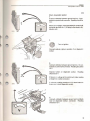
Checks
Fuel system LH2.4 - 240
Components, electrical cables C..,tllo r codf! SII _ Urm:k
U'
Gl{ -= Grey
\\ ;: W hitt:
Y =- \ 0.:1 low
P -= Pink
R =- Red
131. = Brut
!:
Bl'o \\ JI
r; N - {;ri'£ n OR - Or;H1l!e \. 0 ~ Q " ltt Cl ! -= Copper E1
Remove panels under instrument panel right side
and in front of right firewall side.
Remove glove compartment.
Check co ntrol un it ground connections
They should make good contact and fit tightly .
E2
Turn off Ignition
Remove control unit connector
Important ! Ignition must be off before remov
ing or installing the connector.
Press up catch and fold out connector.
E3
Remove connector protective sleeve
Important!
Never check connections from the front.
Experience has shown that they can be
damaged and any faults made worse .
Check connections through the holes on
the connector side. Don 't use unneces
sary strength.
The connection numbers are printed on
the connector side.
38
Checks
Fuel system LH2.4 240
E4
Check diag nostic socket
1.
Connect voltmeter between ground and no. 4 con
nection on con trot unit connector. Reading should be
12 V.
4
<?=:) R
V
II there is no voltage. check lead between control unit
connector and tuse no. 1 (30 strip) in the electric dis ·
tribution unit.
2.
@
Turn on ignition .
Connect selector cable to position 2 on diagnostic
socket.
3.
..,.................
Connect voltmeter betweon ground and no . 12 con
nection on controlunilconnector. Reading should be
12 V.
Derress button on diagnostic socket .
should be 0 V.
GN - 58
<?=:) V
Reading
II there is no voltage allhe conlrol unit. take reading
at diagnostic socket connector.
II voltmeler reading remains at 12 V when buNon is
depressed. check diagnostic socket.
4.
~
Connect voltmeter between ground and red -black
lead 011 diagnostic socket connector. Reading
shoutd be 12 V.
V
39
Checks
Fuel system L H2.4 - 240
5. Connect ohm meter between ground and brown · black lead in diagnostic socket connector. Reading should be approx.On. Turn off ignition.
6.
Connect ohm meter between diagnostic socket se·
lector cable and pin under selector buHon. Reading
should be ~ resistance.
Oepress button . Reading should be 0 n .
"--_ _ _--' 1m,·
7.
Connect diode tester between diagnostic socket tight diode and selector cable. Connect red test pin on diode tester to pin under tight diode and black test pin to selector cable . A reading on the diode tester indicates correct light diode function . With no reading, replace diagnostic socket . "--_ _---I EEE £5
Check ignition lock voltage
~
;
. -&
35
R- sa
40
Turn on ignition .
CO
ct voltmeter between ground and no. 35 con
nection on control unit connector. Reading should be 12 V. Check that voltage exists when starter motor is run
ning.
0=:0 @
V
Turn off ignition .
Checks
Fuel system LH2.4 - 240
III· E6
Check ground connections 5
17
19
29
Connect ohm meIer between ground and connec
tions
S8
BL -SB
S8
0===0
SL
5
17
19
29
on control unit connector. Reading in all cases
should be on.
Leads are grounded to engine intake manifold.
E7
Check Lambda-sond screening lead
Should be co nnected to no. 5 connection on control
unit connector.
8N-~8. E8
Check rpm sensor lead from Ignition system control unit Connect voltmeter between ground and no. 1 con
nection on fuel system control unit connector. 1
8N
<?=0 @ Run starter motor. Reading = battery voltage .
V
E9
Check throttle switch
1. Connect ohm meter between ground and no. 2 con
nection on control unit connector. Reading'should be 0/0 (switch closed) . 2
Y_w
0===0
SL
2.
Depress gas pedal slighlly. Resistance should increase to 2 -3 kohm (throttle sWitch opens) 41
Checks
Fuel system L H2.4 - 240
3.
Connect ohm meter between ground and no. 3 con
nection on control unit connector. Reading should be
= resistance (full load switch open).
4.
3
Depress gas pedal all the way Reading should be 0 n. BL-W
If fault occurs: Measure at throttle switch to see if fault is in throttle switch or in leads . Check ground connection at intake manifold. E10
Check air mass meter
Connect ohm meter between connections 6 and 7 on
control unit connector. Reading should be 2.5·4.00.
(See also E 13 and E27 for checking air mass meter.)
E11
Check system relay primary relay Connect voltmeter between ground and no. 9 con
nection on control unit connector. Connect lead between ground and no.21 connection on control unit connector. Relay should activate. Reading should be battery voltage (approx 12 V). Do not remove ground connection to no. 21 connec
tion. 42
Checks
Fuel system LH2.4 - 240
'II~
E12
y:~
Check sys tem relay pump relay
Connect lead between ground and no. 20 connection
on conlrol unil connector.
21..1.
20
Pump relay should close and start fuel pumps .
Remove ground conneclion lrom no. 20 connection,
bul leave conneclion 10 no. 21.
9
OR
v
E13
ChlM:k air mass meter
1.
Remove rubber sleeve from air mass meier connec·
lor to Iree leads.
S8 s Blll ch
(;R = (; rl' ~
W = " hit c
R . Red
Colour COOl!
fl N :II Brown
V = Vdlow
P = Pink
nr. ..
(; , _ Grecn
OR ~ () J1l n ~ \!
VO = Viu fc l
opper
ell .. (
Blu r
2.
Connect vollmeter between ground and no. 5 con·
nection on alr mass meter connector. Reading
should be approx. 12 V.
v
!l!!!!' -_ _ _...
43
Checks
Fuel system LH2.4 - 240
~I~-
E12
Check system relay pump relay
Connecllead belween ground and no. 20 connection
on control unit connector.
21
6
')
20
Pump relay should close and start fuel pumps .
Remove ground connection from no. 20 connection,
but leave connection to no. 21 .
9
OR
v
E13
Check air mass meter
1.
Remove rubber sleeve from air mass meter connec
tor to free leads.
su = Dlurk
OR = (; r e~
W ;- Wllit e
R !! Red
,
Colour cOfle UN =. Drown G\\ ::: Green Y z:; Yl.'lIuw
OR -= Ora nge P = Pin k
VU = Vinle t RL Ulu~
CU = Coppe r
n
J
G- ~1
. 0
.
21
2.
Connect voltmeter between ground and no. 5 con
nection on air mass meter connector. Reading
should be approx. 12 V.
~
!ill!! \I
V
I
43
Checks
Fuel system LH2.4 240
3.
Connect voltmeter between no. 1 connection
(ground) and no. 5 connection (current feed from
system relay) on air mass meter connector.
Reading should be approx . 12 v.
Remove ground connection to no. 21 connection on
control unit connector.
0=::>
uu~ ~
V
__________
~
E14
Check coolant temperature sensor Connect ohm meter between ground and no. 13 con
nection in control unit connector. Resistance depends on temperature. Guide line values : Resistance at 8,260- 10,560n
-10°C (WF)
+20°C (68°F) 2,280- 2,720n
290364n
+80°C (176°F)
13
BL- R
See Specifications for chart. If fault occurs : Measure at sensor to see if fault is in sensor or in leads. Check ground connection to intake manifold. E15
14
ON
44
Check lead 10 AC compressor
Connect ohm meter between ground and no. 14 con
nection on control unit connector. Reading should be
0-5IH .
Checks
Fuel sysrcm LH2.4 240
E1B
Check lead Irom AC control unit
Connect ohm meier between ground and no. 15
connection on conlrol unit connector.
Reading at AC oH should be approx. 1 k!l.
Reading at AC on should be approx . to U .
b;-;..---.-_~
(uJou r cu~ -.-:-:::-:
SO.= Ohu:k
Ul\ = Uru\\ n ( ; ~ = t; reen
(i N :: l;tpy
r • Yellow
OR . O r dnge
W - Wh ile
I' . Pink
\10 .:. VllJtl!t
U .:. Red
HI
CU :: CIJPpcr
::a
IHue
Ell
Check Injectors Connect ohm meter between connections 9 and 18 on conlrol unit connector. Reading should be 4 U . If the reading is higher, current is not going through the Injeclors. 18
OR
9
OR
If re sistance is : Approx . 5.3 n Faull in one injector or ils teads . Approx . 8 n
Faull in two injectors or their leads. Approx . 16 n Faull in three injectors or their teads . If the measured resistance is wrong : Remove injector connectors and te st them sepa
rately. Reading tor individual injectors should be 16H. X-________
-J
~
45
Checks
Fuel system LH2.4
240
E18
Check COld slarl valve
Connect ohm meter betwee n connections 9 and 32
on control unit connector. Read,ng should be approx .
10n.
E19
Check knock enrichment sIgnal trom Ignltron
system
Tum on Ignilion .
28
Connect voltmeter between ground and no. 28 con
neelion on control unit connector. Reading should be
approx. 0.7 V.
BN-W
Turn 011 Ignilion .
E20
Check Idle valve
Conneel ohm meIer between connections 9 and 33
on control unH connector.
Reading should be approx . 8 n.
46
Checks
Fllel system LH2.4 - 240
E21
Check speedo meter signal Remove panel under instrument panel on driverside. Disconnect 12 terminal connector from speedome
ter. Connect ohm meter between blue (BL) cable and
no . 34 connection on control unit connector. Reading
should be 0 U_
If fault code series 3-1-' has flashed and resistance
is 0
the speedometer signal is missing.
Reconnec! speedometer cable and remount panel
under instrument panel.
34
BL
E22
Aut om atic transmission :
Check gear selector signal
Put gear selector in position N (Neutral). Connect
ohm meter between gro und and no. 30 connection on
conlrol unit conne clor. Re ading should be 0 U.
Move gear selecto r 10 position D (Drive). Reading
should be - resistance.
The reading should be 0
manual lransmission.
2~~
20:1 BL- GN
in all gears for vehicles with
E23
Check Lambda-sand current feed and p r e- heat
Ing re sistance
1.
Ground connections 20 and 21 on control unit con
nector in order to slart fuel pumps.
47
Checks
Fuel system LH2.4 - 240
2.
Connect voltmeter between ground and the yellow
red (V-R) cable in the two-terminal connector at right
wheel house. Reading should be 12 V.
3. Connect ohmmeter between ground and the yellow
red (V-R) cable in the two-terminal connector at righl wheel house . . Lambda-sond temperature: Cold: +20"C (68"F)
approx. 3 n Hoi: + 350°C (660"F)
approx. 13 n (Hot temperature achieved on idle with hot engine.) E24
Final check of control unit
~
~
Important !
The ignition must always
be oft when removinglin
stalling connector.
Connect connector . Be sure the connector's rubber
gasket is reinstalled before connecting to conlrol unit.
Start engIne
If englne does not start after preceding fuel system
check, test with a new conlrol uni\.
48
Checks
Fuel system LH2.4 - 240
E25
Connect CO meter
Connect CO meter to CO connection on catalytic
converter using 5151 connector.
Run engine
Check CO content.
0=::>
If un satis factory. check again after checking
Lambda-sond in next step.
CO
E26
Check Lambda-sond
1.
Disconnect Lambda-sand connector.
\
2.
Ground lead to control unit. CO content reading should "se. indicating that con
trol unit and its connections are OK. 3.
Connect vollmeterto Lambda-sond. Indicator should
swing back and forth \0 show functi on 01 Lambda
sond.
(Reading at correct CO content should be approx. 0.5
V.)
Connect Lambda-sand connector.
49
Checks
Fue(system LH2. 4
240
E27
Check burn-off cleaning of air m ass m eter hot
wi re
NOTE ! Engine must be hot. Coolant tempera
ture must exceed 60°C (140"F).
JilF,,.L-_
_
_
1. Remove protective rubber sleeve from air mass meter co nnector without disconnecting it from the unit. ~
(~]li~ \ \
BN
N
0 ~
'"
/
BL _ W
0
i
!
-lil
Bl _ GN
!
B L_ R
BL- Y
- 111
L
(<~.r
I
'1
~.
2.
Connect voltmeter between connections 1 and 4.
Rev engine to approx. 35 rls (2,100 rpm). Turn off
engine. After approx. 4 seconds, the voltmeter indi
cator should swing back and forth for approx. 1
second (burn-off cleaning).
"1
Remove voltmeter.
\ .
~
l!:!:1
Install rubber sleeve over connector.
V
E28
Check CO conten t
" the engine does not run satisfactorily even
though no faults have been fou nd, o r If fau lt s that
have been found have b een rectifi ed, try using a
new confrol unit.
Remove all test equipment.
<J=:::)
CO
50
Reinstall electrical distribution unit. panels, etc.
Checks
Fuel sysrem L H2.4 - 240
Quick check of injectors
F1
1.
@
Turn on ignition
Depre ss diagn os tic socket bu tton three times. Each
press should last fo r alleast one seoond but nol more
than three .
At this poinl th e injectors will begin 10 operate, fol
lowed by Ihe idle valve, etc. The diagnostic socket
lighl diode will lIash in a oontinuo us pattern.
The conlrol fun ction will repeat itself until interrupted,
th e Ignilion or by changing oontrol
either by tu rn ing
function via the selector button.
0"
2.
listen to and fe el by hand each injector to make sure
they all work.
If one does not function (no click can be heard),
change connector to a valve Ihal does work. It the
fault moves to one Ihal was O.K. before tilen the faull
Is in the connector lead .
3,
It Ihe injeclor still doesn'l wOrk. Ihe fault is probably in
the injector.
Ch eck the injector separalely by connecting an ohm
meter between the injector pins.
Reading (depending somewhat on temperature)
shou ld be approx. 16!U .
4.
fin is h up
0"
'---------~ ~
Turn
ignition and re move
all equipment.
51
Checks
Fuel system L H2.4 - 240
Injectors, fuel distribution pipe and
pressure regulator, remove/install
Removelinstall fuel distribution pipe, injectors and
cold stare valve as one unit.
NOTE! Check that all ground connections are cor
rectly grounded when reconnecting ,them.
Use brace to loosenltighten fuel lines and all other
fasteners.
Check O-rings, Lubricate
them with vaseline or a
similar substance.
Place pressure regulator against fuel distribution pipe and bolt it to the bracket. Check vacuum hose and return hose. 52
PAGE 53
Intentionally Left Blank
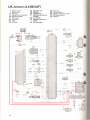
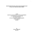
LH-Jetro nic 2.4 (B230F) 131
132
162
21 1
Diagnostic unit
Idle valve
Lambda .ond
Electronic control un it ,
EZl16K
212 In-line fuse
214 Electronic control unit ,
LH2 .4
215 Air mass meter
3 Ignition switch
7 Starter motor
10 Fuse box
32 Connection at instrument
95 Cold start injector
97 Tank pump
100 Fuel pump
112 Joint
129 AC Relay
217
218
221
223
225
Ma in relay
Th rottle switch
Coolant temperature sensor
AC pressure switch
Injectors
o
IlL- Y
pl!l 7
c=ts
1 14
o@ I I~
UI '
",
VI
215
DL- Y
Vl
t>
81
G'-Y -
R \\ •
R
D- R-sa
W
B~
2 18 OJ
nL-'"
su
2 11
0
OR
y_W
y_w
BI .- R -
c::t:f®
22 1
0
32/2
"
ilL "
"
p
p
223
GN
129/2
GR- R
0
0
GN
"
OR R
W SB
RN '
D
,
R~
2.'
2S
J - - . - -". Bl'- W
131
)1(0
2 c·
40
n ~ -s u K- SH
OJ
'5'
Z.
G~--.<'; H
R 58
o
21
.,
OR
21 Y SO
OR
po R-Sa
OR Ul -G..... Y- R
,0
~,I--B-L- ;~
.. III
BL SB
11\1 SR
,.
162
~
~i===========,
(i }l
VO
3~/V
II
0
Y- R
Y
R
B:J:;l' __---"
==''==Y
-=
=
Rh:::::.
JiJR
l::JOCBOOCDOO
ICC
0
Y"
=
"
YR
Q
'"
54
IO
lJ
'" c
100
LH-Jetronic 2.4 (B 230 F) 3
211 \ ,0\'
10
214
~J;.~~ti1~~~~-r:~.:lJUI
~~~~'::t'
I
l
=212::------'
)
I
~
132
55