1
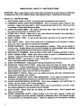
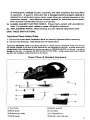
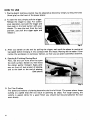
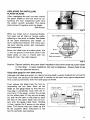
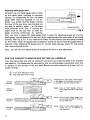
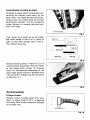
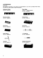
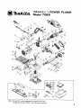
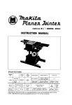
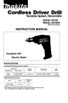
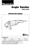
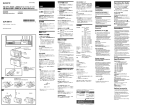
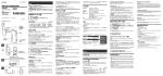
155"
(6%")MODEL 1805B
INSTRUCTION MANUAL
DOUBLE
INSULATION
SPECI FICAT I0 NS
Planing
width
Planing
depth
AMPS
(115Vl
No load
speed
Overall
length
Net
weight
Power
supply cord
155"
(6-1/8")
2mm
(5/64")
15,000
Rlmin.
529 mm
0'5 A
(20-7/8")
8 kg
(17.6 Ibs)
5m
(16.4 ft.1
IMPORTANT SAFETY INSTRUCTIONS
WARNING: When using electric tools, basic safety precautions should always be followed
to reduce the risk of fire, electric shock, and personal injury, including the following:
READ ALL INSTRUCTIONS.
1. KEEP WORK AREA CLEAN. Cluttered areas and benches invite injuries.
2. CONSIDER WORK AREA ENVIRONMENT. Don't use power tools in damp or wet
locations. Keep work area well lit. Don't expose power tools to rain. Don't use tool
in presence of flammable liquids or gases.
3. KEEP CHILDREN AWAY. All visitors should be kept away from work area. Don't
let visitors contact tool or extension cord.
4. STORE IDLE TOOLS. When not in use, tools should be stored in dry, and high or
locked-up place - out of reach of children.
5. DON'T FORCE TOOL. It will do the job better and safer a t the rate for which it
was intended.
6. USE RIGHT TOOL. Don't force small tool or attachment to do the job of a heavyduty tool. Don't use tool for purpose not intended.
7. DRESS PROPERLY. Don't wear loose clothing or jewelry. They can be caught in
moving parts. Rubber gloves and non-skid footwear are recommended when working
outdoors. Wear protective hair covering to contain long hair.
8. USE SAFETY GLASSES. Also use face or dust mask if cutting operation is dusty.
9. DON'T ABUSE CORD. Never carry tool by cord or yank it to disconnect from receptacle. Keep cord from heat, oil, and sharp edges.
10. SECURE WORK. Use clamps or a vise to hold work. It's safer than using your hand
and it frees both hands to operate tool.
11. DON'T OVERREACH. Keep proper footing and balance at all times.
12. MAINTAIN TOOLS WITH CARE. Keep tools sharp and clean for better and safer
performance. Follow instructions for lubricating and changing accessories. Inspect
tool cords periodically and if damaged, have repaired by authorized service facility.
Keep handles dry, clean, and free from oil and grease.
13. DISCONNECT TOOLS. When not in use, before servicing, and when changing accessories, such as blades, bits, cutters.
14. REMOVE ADJUSTING KEYS AND WRENCHES. Form habit of checking to see
that keys and adjusting wrenches are removed from tool before turning it on.
15. AVOID UNINTENTIONAL STARTING. Don't carry plugged-in tool with finger on
switch. Be sure switch is OFF when plugging in.
16. OUTDOOR USE EXTENSION CORDS. When tool is used outdoors, use only extension cords intended for use outdoors and so marked.
17. STAY ALERT. Watch what you are doing, use common sense. Don't operate tool
when you are tired.
18. CHECK DAMAGED PARTS. Before further use of the tool, a guard or other part
that i s damaged should be carefully checked to determine that it will operate properly and perform i t s intended function. Check for alignment of moving parts, binding
2
of moving parts, breakage of parts, mounting, and other conditions that may affect
i t s operation. A guard or other part that is damaged should be properly repaired or
replaced by an authorized service center unless otherwise indicated elsewhere in this
instruction manual. Have defective switches replaced by authorized service center.
Don't use tool if switch does not turn it on and off.
19. GUARD AGAINST ELECTRIC SHOCK. Prevent body contact with grounded surfaces. For example; pipes, radiators, ranges, refrigerator enclosures.
20. REPLACEMENT PARTS. When servicing, use only identical replacement parts.
SAVE THESE INSTRUCTIONS.
Additional Planer Safety Rules
1. Be sure the cutter blade installation bolts are securely tightened before operating.
2. DO not hold housings. Keep hands clear of blades below.
VOLTAGE WARNING: Before connecting the tool t o a power source (receptacle, outlet, etc.) be sure
the voltage supplied is the same as that specified o n the nameplate o f the tool. A power source with
voltage greater than that specified f o r the t o o l can result in SERIOUS I N J U R Y t o the user - as well as
damage t o the tool. If in doubt, DO N O T PLUG IN T H E TOOL. Using a power source w i t h voltage
less than the nameplate rating is harmful t o the motor.
Power Planer & Standard Equipment
0Tool body
0Socket wrench
Q Bevel guide
@Tool Case
0(+) Screwdriver
@Wooden carrying case
@Sharpening holder
@Blade gauge
3
HOW TO USE
1. Planing depth (cutting volume) may be adjusted as desired by simply turning the knob
(front grip) on the front of the power planer.
2. To start the tool, simply pull the trigger.
Release the trigger to stop. For continuous operation, just pull the trigger and
then push in the lock button with your
thumb. To stop the tool from the lock
position, just pull the trigger again and
release it.
3. After you switch on the tool by pulling the trigger, wait until the planer is running a t
top speed before bringing it into contact with the wood. Planing will be easier if you
incline the workpiece in stationary fashion, so that you can plane somewhat downhill.
4. Starting & Finishing Planing Work
First, rest the tool front shoe flat upon
the work surface. Switch on, then move
the planer gently forward. Appy pressure on front of tool a t start of planing,
and a t the back a t the end of planing.
(See photo)
5. For Fine Finishes
The speed and volume of planing determine the kind of finish. The power planer keeps
cutting a t a speed that will not result in jamming by chips. For rough cutting, the
volume is upped, while for a good finish you should but less and advance the tool
more slowly.
4
REPLACING OR INSTALLING
PLANER BLADES
After unpluggingthe tool, you may remove
the planer blades on the tool drum by unscrewing the four installation bolts with
the socket wrench provided. The clamp
plate comes off together with the blades.
(See Photo)
Fig. 3
When you install new or sharpened blades,
first clean out all chips or foreign matter
adhering to the drum or blades. Use blades
of the same dimensions and weight, or
drum oscillation/vibration will result, causing poor planing action and, eventually,
tool breakdown.
Hex. flange hd. bolt I
Screw the blade onto the adjust plate, slip
it into the groove on the drum, then fit the
blade clamp on over it. Fasten with hex
flange hd. bolt. See right diagram.
Blade clamr, Dla
Adjust plate
Fig. 4
Caution: Tighten carefully the cutter blade installation bolts when attaching cutter blades
to the planer. A loose installation bolt can be dangerous. Always check to see
they are tightened securely.
Using blade gauge for even blade setting
Although the blade protrusion for desired cutting depth i s easily obtained by turning the
front knob, the setting of the blade itself in relation to the work may require adjustment.
This i s done conveniently with the blade gauge provided.
First, remove the blade from the tool by
unscrewing the hex bolts. Now, set the
blade on the gauge blade so that the cutting edge i s completely flush with the inside flank of the gauge. Loosen the screws
on the adjust plate (if they are not already
so) and use the back of side plate to push
the heel of the planer blade into full contact with the gauge inside flank. Holding
it thus, tighten the 2 screws on the adjust
plate. This insures that your blade tip will
be set properly when remounted in the
tool for perfectly even planing.
Planer blade
'
\
Gauge base
Fig. 5
5
Adjusting blade gauge itself
t
,
Constant use of a blade gauge leads to wear
on the inside flank, resulting in improper
settings. To compensate for this, the blade
gauge itself must be adjusted. If, for example, you notice t h a t the blade is below
the level of the rear shoe, you probably are
not able to actually plane - so the blade
Adjusting screw
must protrude more. But, if turning the
Fig.
depth knob all the way fails to make the
blade protrude sufficinetly for planing,
then you have to adjust the blade gauge itself. Loosen the adjusting screws set into the
blade gauge, turning them to the left until their heads contact the inner walls of the inside
notches. (See Fig. 5,6.) If you need more leeway for adjustment than the space provided
by the notch, loosen the gauge plate installation screws on top to move the guage plate as
required. After adjusting the gauge plate for correct blade settings, secure the top screws
and inside adjusting screws.
n
/
Note: Do not turn the adjusting screws except a t the time of this adjustment.
FOR THE CORRECT PLANER BLADE SETTING (ALL MODELS)
Your planing surface will end up unsmooth and not level, unless the blade i s set properly
and securely. The blade must be mounted so that the cutting edge is absolutely level, that
is, parallel to the surface of the rear base. Below are some examples of proper and improper settings.
( A ) Front base (Movable shoe)
(B) Rear base (Stationary shoe)
Correct
setting
=m
Although this side view cannot show
it, the edges o f the baldes run perfectly parallel t o the rear base surface.
m?)
Cause: One o r b o t h blades fails t o
have edge parallel t o rear base
line.
at start
Gouging
at end
6
~~
E2aT(
Cause: One or b o t h blade edges fails
t o protrude enough in relation
t o rear base line.
Cause: One o r b o t h balde edges protrudes t o o far in relation t o
rear base line.
SHARPENING PLANER BLADES
Although a power planer considerably outperforms an ordinary hand plane, by the
same token the blades become dull faster.
Always keep your blades sharp for the best
performance possible. Use the sharpening
holder (photo) to remove nicks and produce a fine edge.
Sharpening holder
Fig. 7
First, loosen the 2 wing nuts on the holder
and insert blades A and B as in figure a t
right, so that they contact side C and D.
Then tighten wing nuts.
Wing nut
Side (CJ
Blade(B1
\
Side(D1
\
Fig. I
Immerse dressing stone in water for 2 or 3
minutes before sharpening. Hold the holder
so that blades both contact the dressing
stone for simultaneous sharpening a t the
same angle. Stock removal i s possible up to
7.5 mm (5/16"). Blades may be used down
(1").
to24.5"
Fig. 9
MAINTENANCE
Carbon brushes
Replace carbon brushes when they wear
down to about 6 mm (1/4") or sparking
will occur. Both brushes should be changed
a t the same time.
L-.
..
U
6mm ( 1/4")
Fig. 1(
7
ACCESSORIES
CAUTION :
The accessories specified in this manual are recommended for use with your Makita Power Planer.
The use of any other accessory might be hazardous.
Replacement Blades
(Part No. 731010-3)
Planer Blades
(Material : Tungsten-carbide)
(Part No. 731204-0)
Sharpening Holder
(Part No. 123006-2)
Dressing Stone
(Part No. 741801-4)
Blade Gauge
(Part No. 123009-6)
Bevel Guide
(Part No. 123053-3)
Socket Wrench
(+) Screwdriver
(Part No. 783002-8)
(Part No. 782209-3)
Tool Case
(Part No. 824001 -2)
8
Wooden Carrying Case
(Part No. 821087-7)
@-
I
POWER PLANER
Model 18058
155"(6)/,")
I
I
Note: The switch, noise suppressor, plug and other part
configurations may differ from country t o country.
9
GtD
M
t:'
DESCRIPTION
1
1
'LtM
DESCRIPTION
MACHINE
MACHINE
CORD ASSEMBLY
I A m m b l s d Cord. Plup E Cord Guard1
42
1
4
Drum Housing
43
P. H. S c n w M4xJ) (With Washer1
U
1
V.PuIIey 6-30
P. H. Screw M4x14 (With Washer1
2
2
3
2
P. H. Screw M4xl8 IWah Washerl
45
1
Rubber Pin 6
4
1
Strain R e l d
46
4
P. H. Screw M4r5 (With Washed
1
Cord Guard
41
e
H. F. H. 8011 M6x17
48
2
2
Adlusting Plats
1
Front easa
5
6
1
Handle Sat
7
4
P. H. S c n w M5x12 IWiIh W i h e r l
8
2
Brush Holder Cap
49
50
Drum Plate
9
2
Carbon Brush
51
1
Rubber Packing
10
1
Motor Housing (With Brush Holder x 2 E
S.Screw M5xE x 21
52
1
CompassionSpring 24
11
3
P. H. S c n w M5xl8 IWith W ~ h e d
53
2
P. H. Screw M5xB IWith Wahcrl
12
1
Name Plate
54
1
Rubber Pin 4
13
4
R i m 0-5
55
1
B..r,ng
14
1
Switch
56
2
P. H. Screw M5r35 IWith Washed
15
2
2
P. H. Smew M4i6 IWith Washerl
57
2
P. H. Screw M5x10 IWith Washer)
17
58
2
P. H. Smew M 4 x P (With Waherl
18
1
FIELD ASSEMBLY
IWith Garter Spring x 21
59
1
Chip Cowr
60
1
Main Frams
19
2
H. Bolt M5x75 IWiIh Washed
61
1
Holder
20
1
Rubber Pin 4
62
1
P. H. Screw M6x16 (With Washer)
21
1
Ball Bearing BMOLLB
4ccI
22
23
1
Insulation W d m r
100
1
ARMATURE ASSEMBLY
( h m b 1 . d Items 21 - 261
24
1
Fan 80
25
1
Oust 9.1
m
1
Ball Bearing 6201L L B
27
28
1
P. H. Scnw M5x10 IWith Washed
1
0.11 Cow,
i3
1
J)
P. H. Screw M5xJ) (With Washed
COW, 38
e
2
P
,".I
BINIS 155
GUIDE RULE ASSEMBLY
IAmmb1.d Item401 -4031
2
2
C. S. N. Bolt M5r12
402
403
1
Guide Rule
Poly V-Belt 6-304
4n
1
1
V-PuIIoy 6-23L
405
1
31
5
P. H. Screw M5140 (With WMIWrI
406
2
P. H. Snm M5r14 (With Washer)
32
1
Bracket
407
2
Screw M5r13
33
1
Rubber Pin 6
34
1
Washer 26
u)8
2
409
1
P r w r a Plats
410
411
1
Sharpening Holder
2
C. S. N. Bolt M 6 x a
412
1
Screwdriver
413
414
1
1
Socket Wrench 9
Drum
W r b r 12
415
1
Wooden Carrying Case
Ball Bearing 620122
--
401
12
35
1
Adlusting Knob 64
36
F. Washer 13
37
1
1
38
1
Washer 10
81
.1 Bearing 62M)ZZ
DRUM ASSEMBLY
1Arrmbl.d Items 31 - 41 E 46 - 491
39
4a
1
1
-41
1
W. N u l M5
BLADE GAUGE ASSEMBLY
1 A u m b l . d Items404 - 4071
&up. P1
.I.
up. e-
SHARPENING HOLDER ASSEMBLY
1AmmM.d l 1 ~ m s 4 0 - 4 1 1 l
W. Nu1 Me
Tool
c.U
Note: The switch, noise suppressor, plug and other pert specifications may differ from country to country.
10
P
MAKI’LALIMITED ONE YEAR WARRANTY
Warranty Policy
Every Makita tool is thoroughly inspected and tested before leaving the factory. It is warranted to
be free of defects from worlananship and materials for the period of ONE YEAR from the date of
original purchase. Should any trouble develop during this one-year period, retum the COMPLETE
tool, freight prepaid, to one of Makita’s Factory or Authorized Service Centers. If inspection shows
the trouble is caused by defective workmanship or material, Makita will repair (or at our option,
replace) without charge.
This Warranty does not apply where:
0
repairs have been made or attemuted by others:
repairs are required because of normal wear and tear:
The tool has been abused, misused or improperly maintained;
alterations have been made to the tool.
IN NO EVENT SHALL MAKITA BE LIABLE FOR ANY INDIRECT, INCIDENTAL OR CONSEQUENTIAL DAMAGES FROM THE SALE OR USE OF THE PRODUCT. THIS DISCLAIMER
APPLIES BOTH DURING AND AFTER THE TERM OF THIS WARRANTY.
MAKITA DISCLAIMS LIABILITY FOR ANY IMPLIED WARRANTIES, INCLUDING IMPLIED
WARRANTIES OF “MERCHANTABILITY” AND “FITNESS FOR A SPECIFIC PURPOSE,
AFTER THE ONE-YEAR TERM OF THIS WARRANTY.
This Warranty gives you specific legal rights, and you may also have other rights which vary from
state to state. Some states do not allow the exclusion or limitation of incidental or consequential
damages, so the above limitation or exclusion may not apply to you. Some states do not allow
limitation on how long an implied warranty lasts, so the above limitation may not apply to you.
~~
wmnLb,Ltd.
11-8,3-chome, Sumiyoshi-cho. Anjo, Aichi 446, Japan
883004 - 06 7 C
PRINTED IN JAPAN
1985-1 1 -N