1
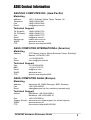
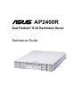
®
AP2400R
Dual Pentium® III 2U Rackmount Server
Reference Guide
Disclaimer/Copyrights
Checklist
No part of this manual, including the products and software described in it, may be
reproduced, transmitted, transcribed, stored in a retrieval system, or translated into
any language in any form or by any means, except documentation kept by the purchaser
for backup purposes, without the express written permission of ASUSTeK COMPUTER
INC. (“ASUS”).
ASUS PROVIDES THIS MANUAL “AS IS” WITHOUT WARRANTY OF ANY KIND,
EITHER EXPRESS OR IMPLIED, INCLUDING BUT NOT LIMITED TO THE IMPLIED
WARRANTIES OR CONDITIONS OF MERCHANTABILITY OR FITNESS FOR A
PARTICULAR PURPOSE. IN NO EVENT SHALL ASUS, ITS DIRECTORS,
OFFICERS, EMPLOYEES OR AGENTS BE LIABLE FOR ANY INDIRECT, SPECIAL,
INCIDENTAL, OR CONSEQUENTIAL DAMAGES (INCLUDING DAMAGES FOR
LOSS OF PROFITS, LOSS OF BUSINESS, LOSS OF USE OR DATA,
INTERRUPTION OF BUSINESS AND THE LIKE), EVEN IF ASUS HAS BEEN
ADVISED OF THE POSSIBILITY OF SUCH DAMAGES ARISING FROM ANY
DEFECT OR ERROR IN THIS MANUAL OR PRODUCT.
Product warranty or service will not be extended if: (1) the product is repaired, modified
or altered, unless such repair, modification of alteration is authorized in writing by
ASUS; or (2) the serial number of the product is defaced or missing.
Products and corporate names appearing in this manual may or may not be registered
trademarks or copyrights of their respective companies, and are used only for
identification or explanation and to the owners’ benefit, without intent to infringe.
The product name and revision number are both printed on the product itself. Manual
revisions are released for each product design represented by the digit before and
after the period of the manual revision number. Manual updates are represented by
the third digit in the manual revision number.
For previous or updated manuals, BIOS, drivers, or product release information, contact
ASUS at http://www.asus.com.tw or through any of the means indicated on the following
page.
SPECIFICATIONS AND INFORMATION CONTAINED IN THIS MANUAL ARE
FURNISHED FOR INFORMATIONAL USE ONLY, AND ARE SUBJECT TO CHANGE
AT ANY TIME WITHOUT NOTICE, AND SHOULD NOT BE CONSTRUED AS A
COMMITMENT BY ASUS. ASUS ASSUMES NO RESPONSIBILITY OR LIABILITY
FOR ANY ERRORS OR INACCURACIES THAT MAY APPEAR IN THIS MANUAL,
INCLUDING THE PRODUCTS AND SOFTWARE DESCRIBED IN IT.
Copyright © 2001 ASUSTeK COMPUTER INC. All Rights Reserved.
Product Name:
AP2400R (ASUSPRO 2400R)
Manual Revision: 1.00 E750
Release Date:
April 2001
2
Introduction: About This Manual
ASUS Contact Information
Features
ASUSTeK COMPUTER INC. (Asia-Pacific)
Marketing
Address:
Telephone:
Fax:
Email:
150 Li-Te Road, Peitou, Taipei, Taiwan 112
+886-2-2894-3447
+886-2-2894-3449
[email protected]
Technical Support
Tel (English):
Tel (Chinese):
Fax:
Email:
Newsgroup:
WWW:
FTP:
+886-2-2890-7123
+886-2-2890-7113
+886-2-2893-7775
[email protected]
news2.asus.com.tw
www.asus.com.tw
ftp.asus.com.tw/pub/ASUS
ASUS COMPUTER INTERNATIONAL (America)
Marketing
Address:
Fax:
Email:
6737 Mowry Avenue, Mowry Business Center, Building 2
Newark, CA 94560, USA
+1-510-608-4555
[email protected]
Technical Support
Fax:
BBS:
Email:
WWW:
FTP:
+1-510-608-4555
+1-510-739-3774
[email protected]
www.asus.com
ftp.asus.com.tw/pub/ASUS
ASUS COMPUTER GmbH (Europe)
Marketing
Address:
Fax:
Email:
Harkortstr. 25, 40880 Ratingen, BRD, Germany
+49-2102-442066
[email protected] (for marketing requests only)
Technical Support
Hotline:
MB/Others: +49-2102-9599-0
Notebook: +49-2102-9599-10
Fax:
+49-2102-9599-11
Support (Email): www.asuscom.de/de/support (for online support)
WWW:
www.asuscom.de
FTP:
ftp.asuscom.de/pub/ASUSCOM
AP2400R Hardware Reference Guide
3
FCC/CDC Statements
Safeguards
Federal Communications Commission Statement
This device complies with FCC Rules Part 15. Operation is subject to the
following two conditions:
•
•
This device may not cause harmful interference, and
This device must accept any interference received including
interference that may cause undesired operation.
This equipment has been tested and found to comply with the limits for a
Class B digital device, pursuant to Part 15 of the FCC Rules. These limits
are designed to provide reasonable protection against harmful interference
in a residential installation. This equipment generates, uses and can radiate
radio frequency energy and, if not installed and used in accordance with
manufacturer’s instructions, may cause harmful interference to radio
communications. However, there is no guarantee that interference will not
occur in a particular installation. If this equipment does cause harmful
interference to radio or television reception, which can be determined by
turning the equipment off and on, the user is encouraged to try to correct the
interference by one or more of the following measures:
•
•
•
•
Reorient or relocate the receiving antenna.
Increase the separation between the equipment and receiver.
Connect the equipment to an outlet on a circuit different from that to
which the receiver is connected.
Consult the dealer or an experienced radio/TV technician for help.
WARNING! The use of shielded cables for connection of the monitor to
the graphics card is required to assure compliance with FCC regulations.
Changes or modifications to this unit not expressly approved by the party
responsible for compliance could void the user’s authority to operate this
equipment.
Canadian Department of Communications Statement
This digital apparatus does not exceed the Class B limits for radio noise
emissions from digital apparatus set out in the Radio Interference Regulations
of the Canadian Department of Communications.
This class B digital apparatus complies with Canadian ICES-003.
4
Introduction: About This Manual
Electrical Safety
Safet y Precautions
Safeguards
Observe the following safety precautions when you are connecting
or disconnecting any devices.
Operation Safety
IMPORTANT
•
•
•
•
•
•
•
•
•
Any operation on this server must be conducted by
certified or experienced engineers.
Before operating your server, carefully read all the
manuals included with the server package.
Before using the server, make sure all cables are correctly
connected and the power cables are not damaged. If any
damage is detected, contact your dealer as soon as
possible.
To avoid short circuits, keep paper clips, screws, and
staples away from connectors, slots, sockets and circuitry.
Before opening the chassis panels, make sure all power
cables are unplugged.
Avoid dust, humidity, and temperature extremes. Place the
server on a stable surface.
If the power supply is broken, do not try to fix it by
yourself. Contact an authorized dealer.
It is recommended that you wear gloves when assembling
or dissembling the server to protect from cuts and
scrapes.
When the server is powered on, heat sinks and the
surfaces of certain IC devices may be hot. Do not touch
them. Check whether the fans are functioning properly.
Tools Required
You need a Philips (cross) screwdriver and a flat screwdriver to install
or remove the components in the server.
AP2400R Hardware Reference Guide
5
Safet y Precautions
Electrical Safety
IMPORTANT
•
•
•
•
Before installing or removing signal cables, ensure that the
power cables for the system unit and all attached devices
are unplugged.
To prevent electrical shock hazard, disconnect the power
cable from the electrical outlet before relocating the
system.
When adding or removing any additional devices to or from
the system, ensure that the power cables for those devices
are unplugged before the signal cables are connected. If
possible, disconnect all power cables from the existing
system before you add a device.
Use one hand, when possible, to connect or disconnect
signal cables to prevent a possible shock from touching
two surfaces with different electrical potentials.
CAUTION
This product is equipped with a three-wire power cable and
plug for the user’s safety. Use the power cable with a properly
grounded electrical outlet to avoid electrical shock.
IMPORTANT
Motherboards, adapters, and disk drives are sensitive to static
electricity discharge. These devices are wrapped in antistatic
bags to prevent this damage. Take the following precautions:
•
•
•
•
•
•
6
If you have an antistatic wrist strap available, use it while
handling the device.
Do not remove the device from the antistatic bag until you
are ready to install the device in the system unit.
With the device still in its antistatic bag, touch it to a metal
frame of the system.
Grasp cards and boards by the edges. Hold drives by the
frame. Avoid touching the solder joints or pins.
If you need to lay the device down while it is out of the
antistatic bag, lay it on the antistatic bag. Before picking it
up again, touch the antistatic bag and the metal frame of
the system unit at the same time.
Handle the devices carefully to prevent permanent
damage.
Introduction: About This Manual
Contents
Disclaimer/Copyrights .................................................................... 2
ASUS Contact Information ............................................................. 3
FCC/CDC Statements .................................................................... 4
Federal Communications Commission Statement .................... 4
Canadian Department of Communications Statement .............. 4
Safety Precautions ......................................................................... 5
Safeguards ................................................................................ 5
Operation Safety ....................................................................... 5
Tools Required .......................................................................... 5
Safety Precautions ......................................................................... 6
Electrical Safety ......................................................................... 6
Introduction .................................................................................. 9
Audience ...................................................................................... 10
Contents Description .................................................................... 10
Conventions ..................................................................................11
Symbols ....................................................................................11
Package Contents ........................................................................ 12
Standard Components ............................................................ 12
Optional Components .............................................................. 12
Chapter 1 System Overview ................................................... 13
Features ....................................................................................... 14
Chassis: ASUS AR-20 ............................................................. 14
Motherboard: ASUS CUR-DLSR ............................................. 14
Front Panel ................................................................................... 15
Back Panel ................................................................................... 15
Power Button and System LEDs .................................................. 16
LED Information ........................................................................... 17
Hard Drive Power & Status LEDs ............................................ 17
System Reset Button ............................................................... 17
Programmable Message LED ................................................. 17
Fan Fail or High Temperature LED .......................................... 17
Power Supply Failure LED ...................................................... 17
Hard Disk Activity LED ............................................................ 17
Power ON LED ........................................................................ 17
System Power Button .............................................................. 17
AP2400R Hardware Reference Guide
7
Contents
Chapter 2 Basic Operation .....................................................
Getting Started .............................................................................
Connect a Monitor ...................................................................
Connect Power Cords .............................................................
Turn the Power ON ..................................................................
Check Power LED ...................................................................
19
20
20
20
20
20
Chapter 3 Hardware Setup ..................................................... 21
Opening the Chassis Cover ......................................................... 22
Under the Chassis Cover ............................................................. 23
Internal Components .................................................................... 24
Motherboard Placement ............................................................... 25
Central Processing Unit (CPU) .................................................... 26
CPU Heatsink ............................................................................... 27
CPU Terminator ............................................................................ 28
Cooling Fans ................................................................................ 29
System Memory ........................................................................... 30
Riser Card / Expansion Card ....................................................... 31
SCSI Backplane ........................................................................... 32
Connecting Cables ....................................................................... 33
Connecting Cables ....................................................................... 34
SCSI Hard Disk Drives ................................................................. 35
Floppy Drive ................................................................................. 37
8
Introduction: About This Manual
You are reading the AP2400R
Server Reference Guide. This
reference guide provides general
and specific information about the
AP2400R server.
“About This Guide” contains an
introduction on the contents of this
document that include target
audience, chapter description, and
conventions used. It also lists the
items included in the system
package.
AP2400R Hardware Reference Guide
About This Guide
Introduction
9
Audience
This guide is intended for experienced users and integrators with
hardware knowledge of personal computers.
Contents Description
This reference guide contains the following parts:
1. Introduction: About This Guide
This part contains an introduction on the contents of this document
that include target audience, chapter description, and conventions
used. It also lists the items included in the system package.
2. Chapter 1: System Overview
This chapter describes the external features of the AP2400R
server. It includes specific sections that identify these features.
3. Chapter 2: Basic Operation
This chapter tells how to get started with the AP2400R server.
The basic operation includes connecting the cables and powering
on the system.
4. Chapter 3: Hardware Setup
This chapter describes the hardware setup procedures that you
have to perform when installing system components. It also gives
detailed information on the internal components and how to install
them.
10
Introduction: About This Manual
Conventions
Symbols
To make sure that you perform certain tasks properly, take note of
the following symbols used throughout this guide.
WARNING: Information to prevent injury to yourself when
trying to complete a task.
CAUTION: Information to prevent damage to the components
when trying to complete a task.
IMPORTANT: Information that you MUST follow to complete
a task.
NOTE: Tips and information to aid in completing a task.
PHILIPS (CROSS) SCREW DRIVER: A tool required to install
or remove the components in the server.
STANDARD (FLAT) SCREW DRIVER: A tool required to
install or remove the components in the server.
AP2400R Hardware Reference Guide
11
Package Contents
This section lists the items included in the server package.
If you are assembling the server by yourself, make sure to prepare
all the server components before starting. It saves you a lot of time
not having to hunt down components when you need them. The
following checklist specifies the necessary components for the server.
Standard Components
Motherboard
Chassis
Power Supply
Floppy Drive
CD-ROM Drive
PCI Expansion
Cables
S370 CPU Terminator
Rackmount Rails
User’s Manuals
ASUS CUR-DLSR
AR-20 2U Rackmount Chassis (19”)
280W Redundant
Slim 1.44MB
ASUS 50x
Three 64-bit PCI slots
Internal SCSI, IDE, floppy
For use in one processor configuration
R-20 Rackmount Kit
server, motherboard, CD-ROM
Optional Components
RAID Controller
Processor
Memory
Hard Drive
12
ASUS PCI-DA2200 RAID controller
Dual Pentium® III up to 1GHz
Up to 4GB registered ECC SDRAM
Up to six SCA-2 Ultra160 SCSI
Introduction: About This Manual
System
This chapter describes the
external features of the AP2400R
server. It includes specific sections
that identify these features.
AP2400R Hardware Reference Guide
System Overview
Chapter 1
Over view
13
Features
Checklist
The AP2400R is configured for the ASUS CUR-DLSR smart
motherboard that uses the ServerSetTM chipset from ServerWorks®.
The motherboard supports dual Pentium III processors to accelerate
even the most complicated server tasks. The following are highlights
to the server’s many features. For additional information, refer to the
motherboard user’s manual that comes with the server package.
Chassis: ASUS AR-20
•
Chassis: 2U form factor that fits in a standard 19” rack
•
SCSI Backplane: Supports six SCSI hard drives using 80-pin
SCA-2 connectors
•
Power: Redundant (dual) 280W power supplies equipped with
two universal AC input and ATX-compliant output cables
•
Device Bays: Support for one 3.5” slim type floppy device, one
5.25” standard sized CD-ROM drive, and six 3.5” wide/1” high
SCA SCSI hard disk drives in swappable trays
Motherboard: ASUS CUR-DLSR
14
•
Processor: Dual Intel® Pentium III FC-PGA processors running
up to 1GHz
•
Memory: Four 168-pin DIMM sockets that support up to 4GB
PC133 registered SDRAM with ECC support
•
Onboard SCSI: LSI® 53C1010-33 dual-channel Ultra160 SCSI
controller that supports up to 30 SCSI devices using two 68-pin
Wide SCSI connectors
•
Onboard LAN: Dual Intel® 82559 Fast-Ethernet server controllers
that supports 10BASE-T and 100BASE-TX, RJ-45 output
•
Onboard VGA: ATI® Rage XL VGA controller with 4MB PC100
SDRAM
•
Integrated Super I/O: PC97317 controller that supports one
floppy, two serial ports, one printer port, two USB ports, one PS/
2 keyboard, and one PS/2 mouse
•
Expansion Slot: Three 64-bit PCI slots on a riser card for fulllength PCI expansion cards
Chapter 1: System Overview
Front Panel
Features
The front panel of the AP2400R server allows easy access to the
floppy, CD-ROM, and removable hard disk drives. The power button
and the system LED indicators are also located on the front panel
(see next page for descriptions).
System LEDs
ID0
ID3
ID1
ID4
ID2
ID5
Hard Drive Bays
CD-ROM Drive
Hard Drive Bays
Floppy Drive
Back Panel
The server back panel is shown here with labels to each part.
1
8
2
3
9
4
5
10
1. Redundant Power Supplies
2. Redundant AC-In Connectors
3. PS/2 Mouse Port
4. USB Ports 1 and 2
5. Parallel Port
6. Serial Port (COM2)
7. Three PCI Expansion Slots
6
11
7
12
13
8. Power Supply Power LED
9. PS/2 Keyboard Port
10. Serial Port (COM1)
11. Video-Out (VGA) Port
12. LAN Ports 1 & 2 (RJ-45)
13. Very High-Density SCSI Connector
AP2400R Hardware Reference Guide
15
Power Button and System LEDs
The front panel includes system LEDs to indicate fan and thermal
status, hard disk status, and system power status.
1
4
2
5
3
6
7
8
9
1-3. Hard Drive Power & Status LEDs
4-6. Hard Drive Power & Status LEDs
7. System Reset Button
8. Programmable Message LED
9. Fan Fail or High Temperature LED
16
10
11
12
13
10. Power Supply Status & Failure LED
11. Hard Disk Activity LED
12. Power ON LED
13. System Power Button
Chapter 1: System Overview
LED Information
Hard Drive Power & Status LEDs
The SCSI hard drives have individual LEDs. When a hard drive is
installed, the specific LED for that hard drive is ON (steady green)
under normal conditions. If there is a problem, the LED may turn to a
steady amber. These LEDs are unlit when there is no hard drive is
present.
System Reset Button
This button resets (reboots) the system in case it does not respond
to normal commands.
Programmable Message LED
This LED is software programmable to indicate conditions such a
power outage or event warnings.
Fan Fail or High Temperature LED
When fan speeds and temperatures are normal, this LED shows a
steady green. This LED turns to steady amber when fan speeds
decrease or temperatures increase past a critical threshold.
Power Supply Failure LED
This LED lights when there is a serious problem with the power supply.
Hard Disk Activity LED
This LED flickers (green) whenever there is IDE or SCSI activity.
This LED is unlit when there is no disk activity.
Power ON LED
This LED lights up (steady green) when you apply power to the system
by pressing the power button. This LED goes off when you turn off
the system.
System Power Button
The system power button is connected to the motherboard and is
used for turning the system ON or OFF.
AP2400R Hardware Reference Guide
17
18
Chapter 1: System Overview
This chapter tells how to get
started with the AP2400R server.
The basic operation includes
connecting the cables and
powering on the system.
AP2400R Hardware Reference Guide
Basic Operation
Chapter 2
Basic
Operation
19
Getting Star ted
Before you turn on the server, make sure that you have completed
the basic system connections. Follow these steps when starting the
server.
Connect a Monitor
Video-Out (VGA) Port
Connect a VGA-compatible
monitor by plugging the 15-pin
video cable to the video-out port
(blue) on the back of the server.
Connect Power Cords
Connect two power cords to the
AC power connectors on the back
of the server, then plug the power
cords to a grounded source.
Redundant Power Supply AC In
TIP: The utilize the redundancy of
the power cords, connect each one
to a different source, for example,
two separate UPS connected to
two separate power sockets.
Turn the Power ON
Power Button
Hard Drive Warning (Amber)
Fan/Temp
LED
20
Power
LED
Power ON the server by pressing
the power button on the front
panel.
Check Power LED
After powering on the server,
check if the power LED lights up.
Also make sure that all warning
LEDs are normal.
Chapter 2: Basic Operation
This chapter describes the
hardware setup procedures that
you have to perform when
installing system components. It
also gives detailed information on
the internal components and how
to install them.
AP2400R Hardware Reference Guide
Hardware Setup
Chapter 3
Hardware
Setup
21
Opening the Chassis Cover
The AP2400R chassis is a 2U form factor designed for easy assembly
and disassembly, making the installation of internal components very
convenient. At the top of the chassis is a rotating lock that secures
the cover to the chassis.
Unlocking the Cover
To unlock the cover, turn the rotating lock clockwise until the triangle mark
points to OPEN.
Triangle Mark
Rotating Lock
CLOSE
OPEN
Removing the Cover
Slide the top cover toward the front for about an inch, then lift it from the
chassis.
CAUTION
The top cover of the chassis has locking tabs at the rear end that
connect to the inner side of the back panel. Make sure to disengage
the locking tabs before lifting up the cover.
22
Chapter 3: Hardware Setup
Under the Chassis Cover
When you open the cover to the AP2400R, you will see several major
parts as shown in the second picture below.
58cm
43cm
3
4
2
5
6
1
8
1.
2.
3.
4.
5.
6.
7.
8.
7
CPU Blower
CUR-DLSR Motherboard
Redundant Power Supplies
Three SCA bays
CD-ROM Drive (standard 5 1/4”)
Slim 1.44MB Floppy Drive
Three SCA bays
PCI Cage
AP2400R Hardware Reference Guide
23
Internal Components
The AP2400R server interior comprise the motherboard and other
parts that complete the system.
1
2
3
4
9
8
7
6
1.
2.
3.
4.
5.
6.
7.
8.
9.
24
5
CPU Socket 1
CPU Socket 2 (for CPU terminator in 1 CPU configuration)
Memory Sockets for 1, 2, 3, or 4 DIMMs
IDE Connector for standard 5 1/4” CD-ROM Drive
Slim Floppy Drive Cable
SCSI Cable for Hot Swap SCA SCSI Connectors
External Very High Density Connector Interface (VHDCI) SCSI Connector
64-bit PCI Slot for Riser Card
COM2 Serial Port
Chapter 3: Hardware Setup
Motherboard Placement
This section tells how the motherboard is placed into the chassis in
case you need to remove and reinstall it in the future.
NOTE
The motherboard and other internal components of the AP2400R
server are already installed as indicated in the section “Internal
Components”. Refer to the motherboard user’s manual for detailed
technical information about the motherboard.
Placement Direction
When installing the motherboard,
make sure that you place it into
the chassis correctly. The edge
with the external ports goes to the
back panel of the chassis.
Back Panel
Motherboard ports must align
with openings on the chassis.
Motherboard Screws
Place 13 screws in the holes
indicated by circles to secure the
motherboard to the chassis. Do not
overtighten the screws. Doing so
may damage the motherboard.
AP2400R Hardware Reference Guide
25
Central Processing Unit (CPU)
CPU Orientation
A CPU has a mark (usually a notch or a gold
mark) on one corner to help you identify the
proper orientation and enable you to correctly
install the CPU. Match the marked corner of
the CPU with the marked corner on the socket
to avoid damaging the CPU pins.
CPU Installation
Gold Mark
Figure 1
(1) Unlock the socket by pressing the
lever sideways then lifting it up to a 90°100° angle. See Figure 1.
(2) Position the CPU above the socket
such that its notched or marked corner
matches the socket corner near the end of
the lever, while making sure that the CPU
is parallel to the socket. See Figure 2.
Figure 2
(3) Carefully insert the CPU into the
socket until it fits in place.
(4) When the CPU is in place, press it
firmly on the socket while you push down
the socket lever to secure the CPU. The
lever clicks on the socket indicating that
it is locked.
Gold Mark
Marked Corner
IMPORTANT
The CPU fits only in one orientation. Do not force the CPU into the
socket to prevent bending the pins and damaging the CPU. If the CPU
does not fit completely, check its orientation or check for bent pins.
26
Chapter 3: Hardware Setup
CPU Heatsink
Attaching the Heatsink Front Clip
Place the heatsink on top of
the installed CPU. Attach the
heatsink front clip to the front
of the CPU socket.
(NOTE: When viewed from
the front, the CPU socket has
the lever on the right side.)
Heatsink Front Clip
Socket Lever
Attaching the Heatsink Back Clip
Use a flat screwdriver to attach
the back clip to the back of the
CPU socket until it snaps in place.
AP2400R Hardware Reference Guide
27
CPU T erminator
CPU Terminator Placement
When using only one processor socket, make sure to install an S370
processor terminator to the unused socket. Install a CPU terminator as you
would install a CPU. Refer
to the section “CPU
Installation”.
CPU Socket 2 with
Installed Terminator
CPU Socket 1 with
Installed CPU and
Heatsink
28
Chapter 3: Hardware Setup
Cooling Fans
CPU Blower
The blower shroud extends to the CPU area on the motherboard. The CPU
blower module rests on the PCI cage and power supply with hooks on each
side.
Hooks
CPU Blower
Underside of CPU Blower
CPU1
CPU2
Shroud
Hooks
Expansion Card Fan
Besides the CPU blower, a cooling fan is mounted on the PCI cage to
decrease the temperature of PCI cards. Fan/thermal failures can be
monitored through the LEDs on the front panel and/or by optional software.
8cm PCI Cage Fan
AP2400R Hardware Reference Guide
29
System Memor y
The motherboard has four Dual Inline Memory Module (DIMM) sockets
that support 3.3V Synchronous Dynamic Random Access Memory
(SDRAM) modules in 16, 32, 64, 128, 256, 512MB, or 1GB densities.
DIMM Sockets Location
Locate the DIMM sockets on the
motherboard to install memory
modules.
4 DIMM Sockets
DIMM Installation
(1) Unlock a DIMM socket by pressing
the retaining clips outward. Align a
DIMM on the socket such that the
notches on the DIMM (indicated by
white circles on the figure) match the
breaks on the socket.
DIMM Notches
DIMM Socket Retaining Clip
(2) Carefully insert the DIMM on the
socket until the retaining clips snap
back in place.
CAUTION:
DIMMs fit in only direction. DO
NOT force a DIMM into the
socket to avoid damaging the
DIMM.
30
Chapter 3: Hardware Setup
Riser Card / Expansion Card
The motherboard has a 64-bit PCI expansion slot. The slot requires
a PCI riser card to accommodate PCI expansion cards. The riser
card comes mounted on the PCI cage.
Riser Card
The riser card inserts into the single PCI slot on the motherboard. The card
has three 64-bit PCI card slots for PCI expansion cards.
PCI Cage
PCI Connector
PCI Card Connector
Mounted Riser
Installing an Expansion Card
Carefully insert the golden fingers of the PCI expansion card into the slot on
the riser card. The PCI cage then installs on the chassis in such a way that
will at the same time insert the golden fingers of the riser card into the PCI
slot on the motherboard.
Expansion Card
PCI Slot
Riser Card
AP2400R Hardware Reference Guide
31
SCSI Backplane
The two SCSI backplane supports three Ultra160 SCA SCSI hard
disks each for a total of six. The backplane design incorporates a
hot-swap feature to allow easy connection or removal of SCA SCSI
hard disks. The LED connector on the backplane connects to the
front panel LEDs to indicate HDD access, HDD failure, thermal failure,
and fan failure.
80-pin SCA SCSI Connectors
Front Side
The front side of the backplane has three
80-pin SCA SCSI connectors available for
SCA SCSI hard disks. The hard disks are
externally accessible from the front of the
server.
Back Side
Each backplane includes power, SMB, LED, and SCSI connectors.
Left Board #2 (viewed from back)
SCSI Con. (from right board)
Right Board #1 (viewed from back)
(1)
SCSI In (from motherboard)
SMB in from MB
SMB out to
left board
LED out to
front panel
(2)
(3)
SCSI Connector
(for terminator)
Backplane Power
Connector
SCSI out
to left board
(1) SMB in from right board
(2) SMB out to power supply
(3) LED out to front panel
NOTE
The SCSI backplane is already installed in the system chassis. You
do not need to remove the backplane when installing components
or connecting cables.
32
Chapter 3: Hardware Setup
Connecting Cables
SCSI Cable
Connect the 68-pin SCSI cable to
the SCSI connector on the
motherboard and the other end to
the SCSI In connector on the
backplane board.
SCSI Connector on
the Motherboard
SCSI Connector on
the Backplane
IDE Cable
Connect the IDE cable directly to
the CD-ROM drive connector.
Motherboard
IDE Connector
CD-ROM IDE
Connector
Floppy Cable
Connect the floppy cable directly
to the floppy drive connector. The
slim-type floppy drive uses a flat
ribbon cable. It does not use the
standard floppy drive cable.
Floppy Drive
Connector
Motherboard Floppy
Drive Connector
AP2400R Hardware Reference Guide
33
Connecting Cables
LED & SMB Cable
Connect one end of the LED cable
to the PANEL2 connector on the
motherboard and the other cable
to the SMB connector.
LED Connector on
the Motherboard
LED Connector
on the Backplane
Cooling Fan Cables
Connect the blower fan cable and
PCI cage fan cable to the two
chassis fan connectors on the
motherboard.
Chassis Fan Connectors
34
Chapter 3: Hardware Setup
SCSI Hard Disk Drives
The system comes with three externally accessible SCA hard drive
bays on each side to make a total of six.
Hot-Swap Drive Tray
In each of the HDD bays is a hot-swap
tray for mounting a hard disk drive. Flip
open the tray levers to release the tray,
then slide the tray out of the chassis.
Tray Levers
SCSI HDD Mounting
Place the SCSI hard disk drive to
the hot-swap tray and secure it
with four screws as shown.
HDD Installation
After the drive is secured to the tray, carefully
insert the drive into the bay, then push
the levers back in place.
IMPORTANT
Make sure that the SCSI cable is connected to the motherboard
and the backplane. Refer to the section “Connecting Cables”.
AP2400R Hardware Reference Guide
35
SCSI Hard Disk Drives
Inserting or removing an SCA hard disk is very simple using the hotswap trays.
Removing a Tray
(1) Flip tray levers out
(2) Pull tray out using both
levers with both hands
Inserting a Tray
(1) Flip levers out
(2) Push on both levers with both hands
(3) Flip levers in until it snaps flush with the tray
36
Chapter 3: Hardware Setup
CD-ROM Drive
CD-ROM Installation
Place the CD-ROM drive in its bay
and slide it inward.
Secure the drive to the chassis with
the four levers as indicated by the
arrows. Connect the IDE and
power cables to the CD-ROM.
Floppy Drive
The system comes with the floppy drive already installed. Refer to
this section when you need to replace the floppy drive.
Floppy Drive Mounting
Mount the two brackets to the
floppy drive and secure it with four
screws and connect the white
ribbon cable (compact version of
the standard gray floppy drive
cable). The white ribbon cable
already includes power so there is
no place for a separate floppy
power connector.
AP2400R Hardware Reference Guide
37
Power Supply Connections
Power Supply Connection
The power supply unit contains redundant power supplies and a housing
with five connectors. The connection locations are shown here.
(5)
(4)
(1)
(4) Left SCSI Board
(5) SMBUS (bottom)
(2)
(3)
(2) CD-ROM Drive
(1) Right SCSI Board
(3) Motherboard Power Input
38
Chapter 3: Hardware Setup
Power Supply Swapping
Power Supply Removal
The power supply is redundant and
hot-swappable. Meaning that you
can remove one module while the
server is powered ON.
To remove a power supply module,
squeeze the handle and push
down to eject the individual power
supply module. Then carefully pull
out the power supply module.
AP2400R Hardware Reference Guide
39
40
Chapter 3: Hardware Setup