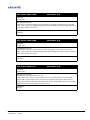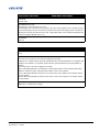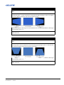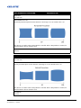
1
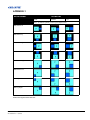
E Series 675/775 Serial Commands
Technical Reference Information
E Series 675/775 Serial Commands Technical Reference Information
020-000576-01 Rev. 1 (10-2012)
Table of Contents
Introduction ......................................................................................................................................1
Message Format................................................................................................................................2
Message Errors .................................................................................................................................3
Size & Position Commands ..............................................................................................................4
(SZP) Size Presets........................................................................................................................4
(OVS) Over Scan .........................................................................................................................4
(PXT) Pixel Track........................................................................................................................4
(PXP) Pixel Phase........................................................................................................................5
(HOR) Horz Position ...................................................................................................................5
(VRT) Vert Position.....................................................................................................................5
(DZH) DIGITAL HORZ ZOOM.................................................................................................6
(DZV) DIGITAL HORZ ZOOM.................................................................................................6
(DSH) Digital Horz Shift.............................................................................................................6
(DSV) Digital Vert Shift..............................................................................................................7
(WRP+SLCT) Geometry Correction ...........................................................................................7
(WRP+VKST) Vert Keystone .....................................................................................................8
(WRP+HKST) Horz Keystone ....................................................................................................8
(HPC) Horzontal Pincushion .......................................................................................................9
(VPC) Vertical Pincushion ..........................................................................................................9
(PCB) Pincushion/Barrel .............................................................................................................10
(CNR) 4-Corner Geometry Correction ........................................................................................11
(CRV) Curve Geometry Correction.............................................................................................12
(ROT) Rotation Geometry Correction.........................................................................................13
(AIM) Auto Image .......................................................................................................................13
Image Setting Commands.................................................................................................................14
(BRT) Brightness.........................................................................................................................14
(CON) Contrast............................................................................................................................14
(CSP) Color Space .......................................................................................................................14
(DTL) Detail ................................................................................................................................15
(CLR) Color.................................................................................................................................15
(TNT) Tint ...................................................................................................................................15
(NRD) Noise Reduction...............................................................................................................16
(FTC) Flesh Tone Correction ......................................................................................................16
(VBL) Video Black Level............................................................................................................16
(FMD) Detect Film ......................................................................................................................17
(CLC) Closed Captions................................................................................................................17
(ROG) Red Gain ..........................................................................................................................17
(GOG) Green Gain.......................................................................................................................18
(BOG) Blue Gain .........................................................................................................................18
(ROO) Red Offset........................................................................................................................18
(GOO) Green Offset ....................................................................................................................18
(BOO) Blue Offset.......................................................................................................................19
(SYT) Sync Threshold .................................................................................................................19
(GOR) RGB Gain/Offset Reset ...................................................................................................19
(PST) Picture Setting ...................................................................................................................20
(DIM) DynamicBlack ..................................................................................................................20
E Series 675/775 Serial Commands Technical Reference Information
020-000576-01 Rev. 1 (10-2012)
i
Table of Contents
(FRZ) Image Freeze .....................................................................................................................20
(BGC) Gamma Curve ..................................................................................................................21
(BCL) BrilliantColor....................................................................................................................21
(WPK) White Peaking .................................................................................................................21
(CCI) Color Temperature.............................................................................................................22
(EDG) Edge Enhancement...........................................................................................................22
(CWS) Color Wheel Speed ..........................................................................................................22
(HSG) Color Enhancement ..........................................................................................................22
Configuration Commands.................................................................................................................23
(LOC) Local Settings ...................................................................................................................23
(FCS) Focus .................................................................................................................................23
(ZOM) Zoom................................................................................................................................23
(LVO) Lens Shift Vertical ...........................................................................................................24
(LHO) Lens Shift Horizontal .......................................................................................................24
(LCB+LOCK) Lock Lens Motors................................................................................................24
(LCB+HOME) Lens Center Calibration......................................................................................24
(CEL) Ceiling Mount Setting.......................................................................................................25
(SOR) Rear Projection .................................................................................................................25
(MSH) Menu Shift Horizontal .....................................................................................................25
(MSV) Menu Shift Vertical .........................................................................................................25
(MBE) Show Messages ( Message Box Enable) .........................................................................26
(OST) Menu Transparency ..........................................................................................................26
(SPS) Splash Screen Setup...........................................................................................................26
(PIV) PIN Protect.........................................................................................................................27
(PCG) Change PIN.......................................................................................................................27
(PWR+STBM) Standby Mode.....................................................................................................27
(APW) Auto Power On ................................................................................................................28
(ASH) Auto Shutdown.................................................................................................................28
(SLP) Sleep Timer .......................................................................................................................29
(HAT) High Altitude....................................................................................................................29
(NET) Network ............................................................................................................................30
(NTW) Wireless Network ............................................................................................................30
(BDR) Serial Port Baud Rate .......................................................................................................31
(SEC) Serial Port Echo ................................................................................................................31
(ADR Projector Address ..............................................................................................................31
(EBL) Edge Blending...................................................................................................................32
(CCA) Color Matching ................................................................................................................33
(HKS) Hot-Key Settings ..............................................................................................................34
Lamp Commands ..............................................................................................................................35
(LPM) Lamp Mode ......................................................................................................................35
(LPP) Lamp Power.......................................................................................................................35
(LPI) Lamp Intensity....................................................................................................................36
(LOP) Current Lamp....................................................................................................................36
(WSP) ECO / Whisper Mode.......................................................................................................36
(LSF) Lamp Auto Switch.............................................................................................................37
(LIF) Lamp Info ...........................................................................................................................37
ii
E Series 675/775 Serial Commands Technical Reference Information
020-000576-01 Rev. 1 (10-2012)
Table of Contents
(LPL) Lamp Life Warning...........................................................................................................37
(LPC) Reset Lamp Hours ............................................................................................................38
(LLC) Light Sensor Calibration...................................................................................................38
Input Switching & PIP Commands ..................................................................................................39
(SIN) Input/source change functions ...........................................................................................39
(PIP) PIP/PBP Functions .............................................................................................................39
(PPS) PIP/PBP Swap ...................................................................................................................39
(PHS) PIP/PBP Size.....................................................................................................................40
(PPP) PIP/PBP Layout.................................................................................................................40
(TMG) Timing Detect Mode .......................................................................................................41
(MIF) Main (Single) Source Info.................................................................................................41
(SIF) Secondary Source Info .......................................................................................................42
(ESH) Enable Main Source Hot Key...........................................................................................42
(MHK) Main Source Hot-Key Settings .......................................................................................42
(SKS) Source Key Function Setting ............................................................................................43
Miscellaneous Commands ................................................................................................................44
(ITP) Test Pattern.........................................................................................................................44
(SST) Projector Status .................................................................................................................45
Service Commands ...........................................................................................................................46
(CWI) Color Wheel Index Setting ...............................................................................................46
(PIF) Projector Info......................................................................................................................46
(DEF) Factory Defaults ...............................................................................................................46
(UID) Enter Service Code............................................................................................................47
(ERR) Error Log ..........................................................................................................................47
(MDT) mODE aDJUSTMENT ...................................................................................................47
Functions Used Only by Serial Command .......................................................................................48
(SIV) E Series Serial command Version .....................................................................................48
(LCE) Last Serial Command Error..............................................................................................48
(LSE) Get Last System Error.......................................................................................................48
(PWR) Power ON/OFF................................................................................................................49
(KEY) Key-Code Entry Setting ...................................................................................................49
(SHU) Shutter ON/OFF Control..................................................................................................50
(OSD) OSD Show/Hide...............................................................................................................50
Appendix-1 .......................................................................................................................................51
PIP/PBP Layout ...........................................................................................................................51
Appendix-2 .......................................................................................................................................52
IR Remote Keycodes ...................................................................................................................52
E Series 675/775 Serial Commands Technical Reference Information
020-000576-01 Rev. 1 (10-2012)
iii
INTRODUCTION
This document describes the serial protocol, consisting of ASCII text messages, used to control the E Series
675/775 projectors.
CONNECTION AND USE
Once you have connected your computer to either the RS232 IN port or to the ETHERNET port on a projector,
you can remotely access projector controls and image setups, issue commands or queries, and receive replies.
Setting up RS232 communication
Connect the projector and host using a null standard cable with 9-pin female to the host, and 9-pin female to
the projector. Pin 2 connects to pin 3, pin 3 connects to pin 2 and pin 5 connects to pin 5.
RS232 Communication parameters
Supported RS232 settings:
PARAMETER
DATA
Baud Rate Default
115200
Parity
None
Data Bits
8
Stop Bits
1
Flow Control
None
NOTE: Use direct connections from laptops and desktops. Docking ports of certain laptops have had issues
with software upgrades
E Series 675/775 Serial Commands Technical Reference Information
020-000576-01 Rev. 1 (10-2012)
1 of 53
MESSAGE FORMAT
1. For all commands, a space may be entered between the code and the number. Example (PXT50), without a
space, can also be entered as (PXT 50), with a space. Both are valid.
2. A modifier can be added to some commands to allow the value to be incremental or decremented, without
having to enter an absolute value. Modifier “n” goes to “next value” and modifier “p” goes to “previous
value”.
For example: The OVS Overscan command allows the values:
(OVS0) : OFF
(OVS1) : ZOOM
(OVS2) : CROP
If the current setting is “Off”, then after (OVS n) is processed, the value will be set to “Zoom”. If the
current setting is “Crop”, then after (OVS p) is processed, the value will be set to “Zoom”.
Messages can be one of three types:
• Set - A command to set a projector parameter at a specific level, such as changing the brightness.
• Request - A request for information, such as what is the current brightness setting.
• Reply - The projector returns the data in response to a request or as confirmation of a command.
All “remote control” information passes in and out of the projector as a simple text message consisting of a
three letter command code, an optional four letter subcode and any related data. Optional features (message
acknowledges) can be included. Regardless of message type or origin, all messages use the same basic format
outlined in Table 1 Message Formats.
Table 1 Message Formats
SOURCE
MESSAGE FORMAT
FUNCTION
EXAMPLES
From Controller
(Code Data)
SET (set contrast to 50)
(CON500) or (CON 500)
(Code+Subcode Data)
SET (set source 1 name to “VGA BOX
1”)
(SNS+SRC1 “VGA BOX
1”)
(Code ?)
REQUEST (what is current contrast?)
(CON?) or (CON ?)
(Code+Subcode ?)
REQUEST (what is lamp 1 hours?)
(LIF+LP1H?)
(Code Data)
REPLY (contrast is 50)
(CON!50)
(Code+Subcode Data)
REPLY (LMP 1 HOURS IS 534)
(LIF+LP1H!534)
From Controller
From Projector
BASIC MESSAGE STRUCTURE
The following component fields comprise a standard ASCII message. Optional fields, such as extra characters
for special modes, restrictions or added functionality, are shown in italics, with the exception of Notes.
• START AND END OF MESSAGE: Every message begins with the left “(“character and ends with the
right “)“character. NOTE: If the start character is received before an end character of the previous message,
the partial (previous) message is discarded.
• PREFIX CHARACTERS (OPTIONAL): For acknowledgement that the projector has responded, and/or
to maximize message integrity, insert a special character before the 3-character function code: # - Full
Acknowledgment, which will cause an echo of the message as a reply to be sent back from the projector
E Series 675/775 Serial Commands Technical Reference Information
020-000576-01 Rev. 1 (10-2012)
2 of 53
when it has finished processing the message. Note that requesting an acknowledgement serves no purpose
when included in a request message, since the acknowledgement will be redundant to the actual reply from
the projector.
• FUNCTION CODE: The projector function you wish to work with, such as contrast, is represented by a
three-character ASCII code (A-Z, upper or lower case). This function code appears immediately after the
leading “(“that starts the message. In messages sent to the projector that do not have a subcode, a space
between the function code and the first parameter (or special character) is optional.
• +SUBCODE: The projector function you wish to work with may have one or more subcodes that will allow
you to select a specific source or subfunction. The subcode is represented by a four-character ASCII code
(A-Z, upper or lower case, and 0-9). This subcode appears immediately after the function code, with a “+”
character to separate the code and subcode. If there is no subcode, the “+” is also omitted. In messages sent to
the projector that do have a subcode, a space between the subcode and the first parameter (or special character) is optional.
• REQUEST/REPLY SYMBOLS: If the controller is requesting information from the projector, a “?” question mark appears directly after the function code. If the projector is replying, a “!” exclamation mark
appears directly after the function code. For set messages to the projector, neither of these characters appear
— data directly follows the code and subcode.
MESSAGE ERRORS
If a command cannot be performed (e.g. syntax error), you will receive a descriptive error indicating the
problem. For example: (ITP) - (65535 00000 ERR00005 "ITP: Too Few Parameters")
E Series 675/775 Serial Commands Technical Reference Information
020-000576-01 Rev. 1 (10-2012)
3 of 53
SIZE & POSITION COMMANDS
(SZP) SIZE PRESETS
READ/WRITE: R/W
SUBCODE
<No Sub code>
Allows modifiers “n” and “p” for selecting “next” and “previous” values.
DESCRIPTION OF USE
Display an image with the detected size, or resize the image by maximizing either the height, width or
both, or resize to the maximum size possible while keeping the original aspect ratio.
EXAMPLES:
(SZP0) : Auto - Display with the detected size. (Default setting)
(SZP1) : Native - Display in its native resolution.
(SZP2) : 4:3 - Retain 4:3 aspect ratio.
(SZP3) : LetterBox - Display with the black borders on the top and bottom.
(SZP4) : Full Size - Fill the screen (regardless of the source).
(SZP5) : Full Width - Fill display width and keep aspect ratio.
(SZP6) : Full Height - Fill display height and keep aspect ratio.
(OVS) OVER SCAN
READ/WRITE: R/W
SUBCODE
<No Sub code>
Allows modifiers “n” and “p” for selecting “next” and “previous” values.
DESCRIPTION OF USE
Controls how edges of the input image are framed and removes noise from around the image.
EXAMPLES:
(OVS0) : OFF
(OVS1) : ZOOM
(OVS2) : CROP
(PXT) PIXEL TRACK
READ/WRITE: R/W
SUBCODE
<No Sub code>
DESCRIPTION OF USE
Steady flickering or several soft vertical stripes or bands across the entire image indicates poor pixel
tracking. Proper pixel
tracking ensures that the image quality is consistent across the screen, the aspect ratio is maintained,
and that the pixel phase can be optimized. This setting adjusts the number of pixel clocks per
horizontal sync in the range 0-100. Default value is 50. Applies only to analog RGB signals.
EXAMPLES:
(PXT50)
E Series 675/775 Serial Commands Technical Reference Information
020-000576-01 Rev. 1 (10-2012)
4 of 53
(PXP) PIXEL PHASE
READ/WRITE: R/W
SUBCODE
<No Sub code>
DESCRIPTION OF USE
Adjusts the phase of the pixel clock created for analog inputs in the range 0 to100. Default value is 50.
EXAMPLES:
(PXP50)
(HOR) HORZ POSITION
READ/WRITE: R/W
SUBCODE
<No Sub code>
DESCRIPTION OF USE
Moves the starting point of the input capture. When applying this function, some of the active area
will be blanked. Increasing the value moves the active image to the right. Valid range is 0 to 100.
Default value is 50.
EXAMPLES:
(HOR50)
(VRT) VERT POSITION
READ/WRITE: R/W
SUBCODE
<No Sub code>
DESCRIPTION OF USE
Moves the starting point of the input capture. When applying this function, some of the active area
will be blanked. Increasing the value moves the active region up. Valid range is 0 to 100. Default value
is 50.
EXAMPLES:
(VRT50)
E Series 675/775 Serial Commands Technical Reference Information
020-000576-01 Rev. 1 (10-2012)
5 of 53
(DZH) DIGITAL HORZ ZOOM
READ/WRITE: R/W
SUBCODE
<No Sub code>
DESCRIPTION OF USE
Change the size of projector's display area horizontally. If the display area has been resized by this
setting, it can be moved by changing the Digital Horz Shift and Digital Vert Shift settings. Valid range
is 50%-400%. Default value is 100.
EXAMPLES:
(DZH100)
(DZV) DIGITAL HORZ ZOOM
READ/WRITE: R/W
SUBCODE
<No Sub code>
DESCRIPTION OF USE
Change the size of projector's display area vertically. If the display area has been resized by this
setting, it can be moved by changing the Digital Horz Shift and Digital Vert Shift settings. Valid range
is 50%-400%. Default value is 100.
EXAMPLES:
(DZV100)
(DSH) DIGITAL HORZ SHIFT
READ/WRITE: R/W
SUBCODE
<No Sub code>
DESCRIPTION OF USE
Valid range for horizontal position is 0 to 100:
At 0 the display area is moved as far as possible to the left, at 50 the display area is horizontally
centered, and at 100 the display area is moved as far as possible to the right. The image must be
“zoomed out” (Digital Zoom) before this function can be used. “Digital Horz Shift” will be disabled
if Digital Zoom has not been applied. Default value is 50.
EXAMPLES:
(DSH50)
E Series 675/775 Serial Commands Technical Reference Information
020-000576-01 Rev. 1 (10-2012)
6 of 53
(DSV) DIGITAL VERT SHIFT
READ/WRITE: WRITE ONLY
SUBCODE
<No Sub code>
DESCRIPTION OF USE
Valid range for vertical position is 0 to 100:
At 0 the display area is moved as far as possible to the top, at 50 the display area is vertically centered,
and at 100 the display area is moved as far as possible to the bottom. The image must be “zoomed out”
(Digital Zoom) before this function can be used. “Digital Horz Shift” will be disabled if Digital Zoom
has not been applied. Default value is 50.
EXAMPLES:
(DSV50)
(WRP+SLCT) GEOMETRY CORRECTION
READ/WRITE: R/W
SUBCODE
SLCT
DESCRIPTION OF USE
Select the type of Geometry Correction to be applied to the image:
"Off/Basic" are available options when the optional Dual Processor Warp Module is not installed, and
"Off/Basic/Curve/Rotate" are available options when the optional Dual Processor Warp Module is
installed.
- Off: No geometry correction is applied to the image.
- Basic: When Warp Module is not installed, keystone and pincushion can be adjusted. When Warp
Module is installed, keystone, pincushion/barrel and 4-corner can be adjusted.
- Curve: When Warp Module is installed, curve and 4-corner can be adjusted. Not available without
the warp module.
- Rotate: When Warp Module is installed, rotate and 4-corner can be adjusted. Not available without
the warp module.
EXAMPLES:
(WRP+SLCT 1) Enable basic settings
E Series 675/775 Serial Commands Technical Reference Information
020-000576-01 Rev. 1 (10-2012)
7 of 53
(WRP+HKST) HORZ KEYSTONE
READ/WRITE: R/W
SUBCODE
HKST
DESCRIPTION OF USE
Horizontal keystone : corrects the distortion created when the projected image is to the left or right of
the lens axis and increasing this value increases right keystoning:
Without Warp Module, valid range is 0-100, and default value is 50. With Warp Module, valid range is
0-20 and default value is 10.
EXAMPLES:
(WRP+HKST 50)
(WRP+VKST) VERT KEYSTONE
READ/WRITE: R/W
SUBCODE
VKST
DESCRIPTION OF USE
Vertical keystone corrects the distortion created when the projected image is above or below the lens
axis, and increasing this value increases positive keystoning:
Without Warp Module, valid range is 0-100, and default value is 50. With Warp Module, valid range is
0-20 and default value is 10.
EXAMPLES:
(WRP+VKST 50)
E Series 675/775 Serial Commands Technical Reference Information
020-000576-01 Rev. 1 (10-2012)
8 of 53
(HPC) HORZONTAL PINCUSHION
READ/WRITE: R/W
SUBCODE
<No Sub code>
DESCRIPTION OF USE
Horizontal pincushion adjusts horizontal distortion. Valid range is 0 to 100. Default value is 50.
This function is available when no Warp Module is installed. When a Warp Module is installed, the
Pincushion/Barrel function should be used.
EXAMPLES:
(HPC50)
(VPC) VERTICAL PINCUSHION
READ/WRITE: R/W
SUBCODE
<No Sub code>
DESCRIPTION OF USE
Vertical pincushion adjusts vertical distortion. Valid range is 0 to 100. Default value is 50.
This function is available when no Warp Module is installed. When a Warp Module is installed, the
Pincushion/Barrel function should be used.
EXAMPLES:
(VPC50)
E Series 675/775 Serial Commands Technical Reference Information
020-000576-01 Rev. 1 (10-2012)
9 of 53
(PCB) PINCUSHION/BARREL
READ/WRITE: WRITE ONLY
SUBCODE
<No Sub code> Adjust Pincushion/Barrel
DESCRIPTION OF USE
Allow for correction for slight curved distortion resulting from the lens or projection surface.
This function is only available when the optional Dual Processor Warp Module is installed.
Valid range is 0-20 and default is 10. The maximum effective adjustment limits are as follows:
EXAMPLES:
(PCB20)
E Series 675/775 Serial Commands Technical Reference Information
020-000576-01 Rev. 1 (10-2012)
10 of 53
(CNR) 4-CORNER GEOMETRY CORRECTION
READ/WRITE: WRITE ONLY
SUBCODE
TLCX Top Left Horizontal adjustment
TLCY Top Left Vertical adjustment
TRCX Top Right Horizontal adjustment
TRCY Top Right Vertical adjustment
BLCX Bottom Left Horizontal adjustment
BLCY Bottom Left Vertical adjustment
BRCX Bottom Right Horizontal adjustment
BRCY Bottom Right Vertical adjustment
DESCRIPTION OF USE
Allow the image to be squeezed to fit an area defined by moving each of the four corners' x and y
position. This function is only available when the optional Dual Processor Warp Module is installed.
Valid range for Horizontal adjustment is 0-190 and for Vertical adjustment is 0-100. Default values are
0. The maximum effective adjustment limits are as follows:
EXAMPLES:
(CNR+TLCZ 20)
E Series 675/775 Serial Commands Technical Reference Information
020-000576-01 Rev. 1 (10-2012)
11 of 53
(CRV) CURVE GEOMETRY CORRECTION
READ/WRITE: WRITE ONLY
SUBCODE
TARC Top Arc
BARC Bottom Arc
LARC Left Arc
RARC Right Arc
DESCRIPTION OF USE
Allow for symmetrical correction of a constant radius horizontal or vertical curve by modifying the
top and bottom of the image only. Compound curves are not supported. The projector should be
mounted perpendicular to the chord of the curve within the offset limitation of the lens used (ideally
on axis). No tilt correction.
This function is only available when the optional Dual Processor Warp Module is installed.
Valid range for curve adjustment is 0-800. Default values are 400. The maximum effective adjustment
limits are as follows:
EXAMPLES:
(CRV+TARC 20)
E Series 675/775 Serial Commands Technical Reference Information
020-000576-01 Rev. 1 (10-2012)
12 of 53
(ROT) ROTATION GEOMETRY CORRECTION
READ/WRITE: WRITE ONLY
SUBCODE
<No Sub code>
DESCRIPTION OF USE
Allow an image to be rotated - most commonly to level the image. While the image is rotated, the
software can crop any content that begins to fall off the panel. The function will not automatically
scale the image down to prevent cropping. If scaling is required, the digital zoom function can be
used, independently of the rotation function.
This function is only available when the optional Dual Processor Warp Module is installed.
Valid range is 0-20. Default value is 10. The maximum effective adjustment limits are as follows:
EXAMPLES:
(AIM1)
(AIM) AUTO IMAGE
READ/WRITE: WRITE ONLY
SUBCODE
<No Sub code>
DESCRIPTION OF USE
Forces the projector to reacquire and lock to the input signal. This is useful when signal quality is
marginal. “Normal mode” can support all of the 4:3 input sources. “Wide mode” can support all of the
16:9 input source and most of the 4:3 input source. For 4:3 input sources not recognized by “Wide
mode” (example 1400 x 1050), perform Auto Image using “normal mode”.
EXAMPLES:
(AIM1)
E Series 675/775 Serial Commands Technical Reference Information
020-000576-01 Rev. 1 (10-2012)
13 of 53
IMAGE SETTING COMMANDS
(BRT) BRIGHTNESS
READ/WRITE: R/W
SUBCODE
<No Sub code>
DESCRIPTION OF USE
Adjusts the overall black level of the projected image by applying an offset to the input image. Valid
range is 0-100. Default value is 50.
EXAMPLES:
(BRT50)
(CON) CONTRAST
READ/WRITE: R/W
SUBCODE
<No Sub code>
DESCRIPTION OF USE
Adjusts the overall white level of the projected image by applying a gain to the input image. This will
adjust the degree of difference between the lightest and darkest parts of the picture. Valid range is 0100. Default value is 50.
EXAMPLES:
(CON50)
(CSP) COLOR SPACE
READ/WRITE: R/W
SUBCODE
<No Sub code>
Allows modifiers “n” and “p” for selecting “next” and “previous” values.
DESCRIPTION OF USE
Select a color space that has been specifically tuned for the input signal.
Useful only for analog signals and certain digital sources. Default value is ‘Auto’.
EXAMPLES:
(CSP0) : RGB
(CSP1) : REC709
(CSP2) : REC601
(CSP3) : RGB Video
(CSP4) : Auto
E Series 675/775 Serial Commands Technical Reference Information
020-000576-01 Rev. 1 (10-2012)
14 of 53
(DTL) DETAIL
READ/WRITE: R/W
SUBCODE
<No Sub code>
Allows modifiers “n” and “p” for selecting “next” and “previous” values.
DESCRIPTION OF USE
Applies a predefined sharpness setting to the current input signal. This adjusts the overall detail of the
projected image. Default value is ‘Normal’.
EXAMPLES:
(DTL0) : Maximum
(DTL1) : High
(DTL2) : Normal
(DTL3) : Low
(DTL4) : Minimum
(CLR) COLOR
READ/WRITE: R/W
SUBCODE
<No Sub code>
DESCRIPTION OF USE
Adjusts the color saturation of analog video sources. Valid range is 0 to 100. Default value is 50.
EXAMPLES:
(CLR50)
(TNT) TINT
READ/WRITE: R/W
SUBCODE
<No Sub code>
DESCRIPTION OF USE
Adjusts the red/green balance of analog video NTSC sources. Valid range is 0 to 100. Default value is
50.
EXAMPLES:
(TNT50)
E Series 675/775 Serial Commands Technical Reference Information
020-000576-01 Rev. 1 (10-2012)
15 of 53
(NRD) NOISE REDUCTION
READ/WRITE: R/W
SUBCODE
<No Sub code>
DESCRIPTION OF USE
Reduces temporal and/or spatial noise in the image. Valid range is 0 to 100. Default value is 0.
EXAMPLES:
(NRD50)
(FTC) FLESH TONE CORRECTION
READ/WRITE: R/W
SUBCODE
<No Sub code>
DESCRIPTION OF USE
Controls the amount of flesh tone correction applied to the image. Valid range is 0 to 100. Default
value is 0.
EXAMPLES:
(FTC50)
(VBL) VIDEO BLACK LEVEL
READ/WRITE: R/W
SUBCODE
<No Sub code>
Allows modifiers “n” and “p” for selecting “next” and “previous” values
DESCRIPTION OF USE
When ‘On’, the projector will analyze the current input image and calculate an offset value which is
then added to the Analog to Digital converter black level value. This ensures optimum black level for
each analog source.
EXAMPLES:
(VBL0) : IRE off.
(VBL1) : IRE on.
E Series 675/775 Serial Commands Technical Reference Information
020-000576-01 Rev. 1 (10-2012)
16 of 53
(FMD) DETECT FILM
READ/WRITE: R/W
SUBCODE
<No Sub code>
Allows modifiers “n” and “p” for selecting “next” and “previous” values.
DESCRIPTION OF USE
Controls film mode detection. This determines whether the original source of the input video was film
(progressive) or video (interlaced), by analyzing motion in the video. This information allows the
projector to correctly display fields from interlaced sources. Default value is ‘Off’.
EXAMPLES:
(FMD0) : Detect film OFF
(FMD1) : Detect film ON
(CLC) CLOSED CAPTIONS
READ/WRITE: R/W
SUBCODE
<No Sub code>
Allows modifiers “n” and “p” for selecting “next” and “previous” values.
DESCRIPTION OF USE
Controls closed caption display while audio is muted. If this setting is not off, audio is not muted. The
source is NTSC and contains captions on the selected channel, so the projector will display caption
text overlaid on the image. Default value is ‘Off’.
EXAMPLES:
(CLC0) : off
(CLC1) : CC1
(CLC2) : CC2
(ROG) RED GAIN
READ/WRITE: R/W
SUBCODE
<No Sub code>
DESCRIPTION OF USE
Adjust the gain of the red channel of the image. It will also affect the white of the image. Applies to
VGA/Component signals only. Valid range is 0-100. Default value is 50.
EXAMPLES:
(ROG50)
E Series 675/775 Serial Commands Technical Reference Information
020-000576-01 Rev. 1 (10-2012)
17 of 53
(GOG) GREEN GAIN
READ/WRITE: R/W
SUBCODE
<No Sub code>
DESCRIPTION OF USE
Adjust the gain of the green channel of the image. It will also affect the white of the image. Applies to
VGA/Component signals only. Valid range is 0-100. Default value is 50.
EXAMPLES:
(GOG50)
(BOG) BLUE GAIN
READ/WRITE: R/W
SUBCODE
<No Sub code>
DESCRIPTION OF USE
Adjust the gain of the blue channel of the image. It will also affect the white of the image. Applies to
VGA/Component signals only. Valid range is 0-100. Default value is 50.
EXAMPLES:
(BOG50)
(ROO) RED OFFSET
READ/WRITE: R/W
SUBCODE
<No Sub code>
DESCRIPTION OF USE
Adjust the offset of the red channel of the image. It will also affect the black and white of the image.
Applies to VGA/Component signals only.Valid range is 0-100. Default value is 50.
EXAMPLES:
(ROO50)
(GOO) GREEN OFFSET
READ/WRITE: R/W
SUBCODE
<No Sub code>
DESCRIPTION OF USE
Adjust the offset of the green channel of the image. It will also affect the black and the white of the
image. Applies to VGA/Component signals only. Valid range is 0-100. Default value is 50.
EXAMPLES:
(GOO50)
E Series 675/775 Serial Commands Technical Reference Information
020-000576-01 Rev. 1 (10-2012)
18 of 53
(BOO) BLUE OFFSET
READ/WRITE: R/W
SUBCODE
<No Sub code>
DESCRIPTION OF USE
Adjust the offset of the blue channel of the image. It will also affect the black and white of the image.
Applies to VGA/Component signals only. Valid range is 0-100. Default value is 50.
EXAMPLES:
(BOO50)
(SYT) SYNC THRESHOLD
READ/WRITE: R/W
SUBCODE
<No Sub code>
DESCRIPTION OF USE
Adjusts the sync threshold for sync-on-green (SOG) signals. This controls the voltage at which a
negative pulse is determined to be a sync instead of active video. The setting is needed anytime the
active video source places its sync on the green/luma channel. Valid range is 0 to 100. Default is 50.
EXAMPLES:
(SYT50)
(GOR) RGB GAIN/OFFSET RESET
READ/WRITE: R/W
SUBCODE
<No Sub code>
DESCRIPTION OF USE
Reset the Red, Green and Blue gain and offset values.
EXAMPLES:
(GOR1): Reset RGB Gain/Offset settings.
E Series 675/775 Serial Commands Technical Reference Information
020-000576-01 Rev. 1 (10-2012)
19 of 53
(PST) PICTURE SETTING
READ/WRITE: R/W
SUBCODE
<No Sub code>: Set picture setting
USER : Store current settings to User Mode. Allows modifiers “n” and “p” for selecting “next” and
“previous” values.
DESCRIPTION OF USE
Changing this setting updates values of picture-related settings (for the current source only) to a set of
predefined values. It will optimize the projector for displaying images under certain conditions, such
as presentation, video, bright, whiteboard, blackboard, beige wall and user definable preset. It will
affect Gamma, Sharpness, White Peaking, Overscan, Brightness, Contrast, Color, Tint, Red Gain,
Green Gain, Blue Gain, Red Offset, Green Offset, Blue Offset.
EXAMPLES:
(PST0) : Presentation
(PST1) : Video
(PST2) : Bright
(PST3) : Whiteboard
(PST4) : Blackboard
(PST5) : Beige Wall
(PST6) : User
(PST+USER1) : Store current settings to User Mode.
(DIM) DYNAMICBLACK
READ/WRITE: R/W
SUBCODE
<No Sub code>
Allows modifiers “n” and “p” for selecting “next” and “previous” values
DESCRIPTION OF USE
When switched ‘On’, the aperture will constantly adjust based on the amount of black in the current
scene. Default value is 'Off'
EXAMPLES:
(DIM0) : DynamicBlack off.
(DIM1) : DynamicBlack on.
(FRZ) IMAGE FREEZE
READ/WRITE: R/W
SUBCODE
<No Sub code>
“n” and “p” for selecting “next” and “previous” values
DESCRIPTION OF USE
Pause the screen image.
EXAMPLES:
(FRZ 1) Freeze the image
E Series 675/775 Serial Commands Technical Reference Information
020-000576-01 Rev. 1 (10-2012)
20 of 53
(BGC) GAMMA CURVE
READ/WRITE: R/W
SUBCODE
<No Sub code>
Allows modifiers “n” and “p” for selecting “next” and “previous” values.
DESCRIPTION OF USE
Selects gamma correction curve.
EXAMPLES:
(BGC0) : Video
(BGC1) : Film
(BGC2) : Bright
(BGC3) : CRT
(BCL) BRILLIANTCOLOR
READ/WRITE: R/W
SUBCODE
<No Sub code>
DESCRIPTION OF USE
Produce an expanded on-screen color spectrum that delivers enhanced color saturation for bright, trueto-life images. It will increase image brightness but reduce overall color accuracy.
EXAMPLES:
(BCL0) : Normal Look
(BCL1) : Bright Look
(WPK) WHITE PEAKING
READ/WRITE: R/W
SUBCODE
<No Sub code>
DESCRIPTION OF USE
Increase the brightness of whites that are near 100%. Applies to video sources only. Valid range is 0100.
EXAMPLES:
(WPK50)
E Series 675/775 Serial Commands Technical Reference Information
020-000576-01 Rev. 1 (10-2012)
21 of 53
(CCI) COLOR TEMPERATURE
READ/WRITE: R/W
SUBCODE
<No Sub code>
Allows modifiers “n” and “p” for selecting “next” and “previous” values.
DESCRIPTION OF USE
Applies a predefined color temperature to the input signal
EXAMPLES:
(CCI0) : Warmest
(CCI1) : Warm
(CCI2) : Cool
(CCI3) : Bright
(EDG) EDGE ENHANCEMENT
READ/WRITE: R/W
SUBCODE
<No Sub code>
Allows modifiers “n” and “p” for selecting “next” and “previous” values
DESCRIPTION OF USE
Apply edge enhancement.
EXAMPLES:
(EDG0): off.
(EDG1): normal.
(EDG2): Maximum.
(CWS) COLOR WHEEL SPEED
READ/WRITE: R/W
SUBCODE
<No Sub code>
Allows modifiers “n” and “p” for selecting “next” and “previous” values.
DESCRIPTION OF USE
Setting Color Wheel speed to 2 x or 3x setting.
EXAMPLES:
(CWS0) : Set Color Wheel speed to 2x setting.
(CWS1) : Set Color Wheel speed to 3x setting.
(HSG) COLOR ENHANCEMENT
READ/WRITE: R/W
SUBCODE
<No Sub code>
DESCRIPTION OF USE
Apply one of the 2 preset color enhancement modes.
EXAMPLES:
(HSG 1)
E Series 675/775 Serial Commands Technical Reference Information
020-000576-01 Rev. 1 (10-2012)
22 of 53
CONFIGURATION COMMANDS
(LOC) LOCAL SETTINGS
READ/WRITE: R/W
SUBCODE
LANG – Language
Allows modifiers “n” and “p” for selecting “next” and “previous” values.
DESCRIPTION OF USE
Controls which language to display in the OSD.
EXAMPLES:
(LOC+LANG 0) – set the language to English
(LOC+LANG 1) – set the language to Chinese
(LOC+LANG 2) – set the language to French
(LOC+LANG 3) – set the language to German
(LOC+LANG 4) – set the language to Italian
(LOC+LANG 5) – set the language to Japanese
(LOC+LANG 6) – set the language to Korean
(LOC+LANG 7) – set the language to Russian
(LOC+LANG 8) – set the language to Spanish
(FCS) FOCUS
(ZOM) ZOOM
READ/WRITE: WRITE ONLY
SUBCODE
<No Sub code>
Allows modifiers “n” and “p” for selecting “next” and “previous” values.
DESCRIPTION OF USE
Adjust the lens focus or zoom offset.
Or use modifier “n” to increase value by 1 or “p” to decrease value by 1.
EXAMPLES:
(FCS n) to increase focus by 1
(ZOM p) to decrease zoom by 1
E Series 675/775 Serial Commands Technical Reference Information
020-000576-01 Rev. 1 (10-2012)
23 of 53
(LVO) LENS SHIFT VERTICAL
(LHO) LENS SHIFT HORIZONTAL
READ/WRITE: WRITE ONLY
SUBCODE
<No Sub code>
Allows modifiers “n” and “p” for selecting “next” and “previous” values.
DESCRIPTION OF USE
Adjust the lens vertical or horizontal offset.
Or use modifier “n” to increase value by 1 or “p” to decrease value by 1.
EXAMPLES:
(LVO n) to increase vertical position by 1
(LHO p) to decrease horizontal position by 1
(LCB+LOCK) LOCK LENS MOTORS
READ/WRITE: R/W
SUBCODE
LOCK: Lock the Zoom, Focus, Horizontal and Vertical Lens motors.
Allows modifiers “n” and “p” for selecting “next” and “previous” values.
DESCRIPTION OF USE
Select the function to prevent all lens motors from moving. It will effectively lock out any changes
and, override all other lens features. This is useful to prevent lens position changes. Default value is
‘Allow’ movement.
EXAMPLES:
(LCB+LOCK0) : Allow
(LCB+LOCK1) : Locked
(LCB+HOME) LENS CENTER CALIBRATION
READ/WRITE: WRITE ONLY
SUBCODE
HOME: Move to center
DESCRIPTION OF USE
Calibrates the lens and then returns the lens to horizontal and vertical home position. Focus and Zoom
are not affected.
EXAMPLES:
(LCB+HOME1)
E Series 675/775 Serial Commands Technical Reference Information
020-000576-01 Rev. 1 (10-2012)
24 of 53
(CEL) CEILING MOUNT SETTING
READ/WRITE: R/W
SUBCODE
<No Sub code>
DESCRIPTION OF USE
Change the orientation of the image for ceiling-mounted projectors. When set to ‘On’, the image will
be turned upside-down. When set to 'Auto', the projector will automatically sense the orientation of
the projector.
EXAMPLES:
(CEL0) : Ceiling mount off.
(CEL1) : Ceiling mount on.
(CEL2) : Auto.
(SOR) REAR PROJECTION
READ/WRITE: R/W
SUBCODE
<No Sub code>
DESCRIPTION OF USE
Reverse the image so that the image can be projected from behind a translucent screen.
EXAMPLES:
(SOR0) : Off.
(SOR1) : On.
(MSH) MENU SHIFT HORIZONTAL
(MSV) MENU SHIFT VERTICAL
READ/WRITE: R/W
SUBCODE
<No Sub code>
DESCRIPTION OF USE
Adjusts the location of on-screen menus and messages. Valid range is 0 to 100. Default value is 0.
EXAMPLES:
(MSH0) - Set horizontal position of menu to left position.
(MSV50) - Set vertical position of menu to center position.
E Series 675/775 Serial Commands Technical Reference Information
020-000576-01 Rev. 1 (10-2012)
25 of 53
(MBE) SHOW MESSAGES ( MESSAGE
BOX ENABLE)
READ/WRITE: R/W
SUBCODE
USER
Allows modifiers “n” and “p” for selecting “next” and “previous” values.
DESCRIPTION OF USE
Controls whether or not the projector displays OSD messages (e.g. source name when searching or
changing source, slider when changing keystone, etc.). Default value is ‘On’.
EXAMPLES:
(MBE+USER0) : OFF
(MBE+USER1) : ON
(OST) MENU TRANSPARENCY
READ/WRITE: R/W
SUBCODE
<No Sub code>
DESCRIPTION OF USE
Controls amount of transparency of the OSD (for menu and messages). Valid range is 0 to 90. Default
value is 0 (not transparent).
EXAMPLES:
(OST0)
(SPS) SPLASH SCREEN SETUP
READ/WRITE: R/W
SUBCODE
SLCT
Allows modifiers “n” and “p” for selecting “next” and “previous” values.
DESCRIPTION OF USE
Choose which splash screen is to be used when no image or test pattern is displayed. Default value is
‘Factory Logo’.
EXAMPLES:
(SPS+SLCT0) : Factory Logo
(SPS+SLCT 1) : Blue
(SPS+SLCT 2) : Black
(SPS+SLCT 3) : White
E Series 675/775 Serial Commands Technical Reference Information
020-000576-01 Rev. 1 (10-2012)
26 of 53
(PIV) PIN PROTECT
READ/WRITE: R/W
SUBCODE
<No Sub code>
DESCRIPTION OF USE
The PIN (personal Identification Number) allows you to password protect the projector. Once the PIN
feature is enabled, the PIN must be entered before an image can be projected.
EXAMPLES:
(PIV”XXXXX”) : if XXXXX Password is correct, the Pin protect function Toggles.
Note: XXXXX is number from 0 to 9
(PCG) CHANGE PIN
READ/WRITE: R/W
SUBCODE
<No Sub code>
DESCRIPTION OF USE
Change the PIN (Personal Identification Number). Default PIN is ‘12345’.
EXAMPLES:
(PCG”OOOOO,NNNNN”)
OOOOO means old password.
NNNNN means new password.
Note: XXXXX is number from 0 to 9
(PWR+STBM) STANDBY MODE
READ/WRITE: R/W
SUBCODE
STBM
Allows modifiers “n” and “p” for selecting “next” and “previous” values.
DESCRIPTION OF USE
Standby Modes are:
• 0.5W Mode: when this mode has been selected, the power consumption is under 0.5W (to meet
EUP regulation) and only the Keypad gets power. The system cannot power on via “UART/WEB/
USB”.
•Communication Mode: when this mode has been selected, the power consumption is approximately
20W, and both the Keypad and processor are powered. The system can power on via “UART/
WEB/USB”.
EXAMPLES:
(PWR+STBM0) : 0.5W mode
(PWR+STBM1) : Communication.
E Series 675/775 Serial Commands Technical Reference Information
020-000576-01 Rev. 1 (10-2012)
27 of 53
(APW) AUTO POWER ON
READ/WRITE: R/W
SUBCODE
<No Sub code>
Allows modifiers “n” and “p” for selecting “next” and “previous” values.
DESCRIPTION OF USE
Enables and disables the projector’s automatic power on (allows the projector to be turned on using a
wall switch). When this mode been selected, the system will power on automatically and skip standby
mode when AC power is applied. Default value is ‘Off’.
EXAMPLES:
(APW0) : OFF
(APW1) : ON
(ASH) AUTO SHUTDOWN
READ/WRITE: R/W
SUBCODE
<No Sub code>
Allows modifiers “n” and “p” for selecting “next” and “previous” values.
DESCRIPTION OF USE
If the projector is in the Search state for longer than the set time without detecting an active signal, it
automatically powers down to ‘Standby Mode’.
EXAMPLES:
Default value is Off/Never
(ASH0) turns off auto shutdown mode (same as never)
(ASH1) 5 MIN
(ASH2) 10 MIN
(ASH3) 15 MIN
(ASH4) 20 MIN
(ASH5) 25 MIN
(ASH6) 30 MIN
E Series 675/775 Serial Commands Technical Reference Information
020-000576-01 Rev. 1 (10-2012)
28 of 53
(SLP) SLEEP TIMER
READ/WRITE: R/W
SUBCODE
<No Sub code> enables or disables sleep mode.
Allows modifiers “n” and “p” for selecting “next” and “previous” values.
DESCRIPTION OF USE
Allows the projector to automatically power off after it has been on for a specified amount of time.
Timer starts when projector is powered on (or when sleep timer auto power off is canceled). Auto
power off occurs whether or not a source is being displayed.
EXAMPLES:
(SLP0) : OFF.
(SLP1) : 2 Hrs.
(SLP2) : 4 Hrs.
(SLP3) : 6 Hrs.
Default value is Off/Never
(HAT) HIGH ALTITUDE
READ/WRITE: R/W
SUBCODE
<No Sub code>
Allows modifiers “n” and “p” for selecting “next” and “previous” values
DESCRIPTION OF USE
Modify the fan speeds for high altitude.
EXAMPLES:
(HAT0): High Altitude off.
(HAT1): High Altitude on.
E Series 675/775 Serial Commands Technical Reference Information
020-000576-01 Rev. 1 (10-2012)
29 of 53
(NET) NETWORK
READ/WRITE: R/W
SUBCODE
DHCP - Turn DHCP On/Off.
ETH0 - IP address
SUB0 - Subnet mask
GATE - Default gateway
HOST – Projector name
MAC0 - MAC Address
SHOW - Show Network Messages - Turn Messages On/Off.
RSTR - Restart network
RSET - Network Factory Reset - The Projector Name, LAN IP, WLAN IP, and SNMP settings will be
reset.
DESCRIPTION OF USE
Modify the network settings or return network settings back to their factory default values.
EXAMPLES:
(NET+DHCP0)
(NET+HOST”DWU670-E”)
(NET+MAC0”00:E0:47:01:02:3C”)
(NET+SHOW1)
(NET+ETH0”192.168.000.001”)
(NET+RSTR1)
(NET+SUB0”255.255.255.000”)
(NTW) WIRELESS NETWORK
READ/WRITE: R/W
SUBCODE
SLCT - Enable wireless LAN
ETH0 - IP address
SUB0 - Subnet mask
GATE - Default gateway
MAC0 - MAC Address
DESCRIPTION OF USE
Modify the wireless network settings.
EXAMPLES:
(NET+SLCT1)
(NET+MAC0”00:E0:47:01:02:3C”)
(NET+ETH0”192.168.000.001”)
(NET+SUB0”255.255.255.000”)
E Series 675/775 Serial Commands Technical Reference Information
020-000576-01 Rev. 1 (10-2012)
30 of 53
(BDR) SERIAL PORT BAUD RATE
READ/WRITE: R/W
SUBCODE
<No Sub code>
Allows modifiers “n” and “p” for selecting “next” and “previous” values
DESCRIPTION OF USE
Selects the serial port baud rate. Default value is ‘115200’.
EXAMPLES:
(BDR0) : 2400.
(BDR1) : 4800.
(BDR2) : 9600.
(BDR3) : 14400
(BDR4) : 19200.
(BDR5) : 38400.
(BDR6) : 57600.
(BDR7) : 115200.
(BDR8) : 1200.
(SEC) SERIAL PORT ECHO
READ/WRITE: R/W
SUBCODE
<No Sub code>
Allows modifiers “n” and “p” for selecting “next” and “previous” values
DESCRIPTION OF USE
Controls whether the serial port echoes characters. Default value is ‘Off’.
EXAMPLES:
(SEC0) : OFF.
(SEC1) : ON
(ADR PROJECTOR ADDRESS
READ/WRITE: R/W
SUBCODE
<No Sub code>
DESCRIPTION OF USE
Set the projector address (0-9). The projector will respond to an IR remote set either to the same
address as the projector or to an IR remote set to address 0. 0 is the default and universal address. The
address of the IR remote must be set using the PROJ key on the remote.
EXAMPLES:
(ADR 6)
E Series 675/775 Serial Commands Technical Reference Information
020-000576-01 Rev. 1 (10-2012)
31 of 53
(EBL) EDGE BLENDING
READ/WRITE: R/W
SUBCODE
<No Sub code>
SLCT : Enable/disable blending
MRKR : Enable/disable marker
GRID : Enable/disable grid test pattern
COLR: Select solid color test pattern
TOPW : Set top blend width
BTMW : Set bottom blend width
LFTW : Set left blend width
RHTW : Set right blend width
BLOF : Set blend area brightness offset
NBOF : Set non-blend area brightness offset
BGAM : Set blend area gamma drop off curve
DESCRIPTION OF USE
Adjust blend widths and settings to left, right, top and/or bottom sides to create a seamless multiprojector stitched image. This function is only available when a Dual Processing Warp Module is
installed.
EXAMPLES:
(EBL+SLCT 1) : Enable blending
(EBL+MRKR 1) : Enable marker frame
(EBL+GRID 2) : Enable red grid test pattern (0=Off, 1=White, 2=Red, 3=Green, 4=Blue)
(EBL+COLR 2) : Select red solid color test pattern (0=Off, 1=White, 2=Red, 3=Green, 4=Blue)
(EBL+TOPW 200) : Set top blend width to 200 pixels (0-half output height)
(EBL+BLOF 1000) : Set blend area brightness offset (0-2000)
(EBL+NBOF 1000) : Set non-blend area brightness offset (0-2000)
(EBL+BGAM 300) : Set blend area gamma drop off curve (70-300)
E Series 675/775 Serial Commands Technical Reference Information
020-000576-01 Rev. 1 (10-2012)
32 of 53
(CCA) COLOR MATCHING
READ/WRITE: R/W
SUBCODE
MTRA : Meter Adjustment enable
MTTP : Enable Auto Test pattern for meter adjustment items
RDMI : Measured data - Intensity of red
RDMX : Measured data - x coordinate of red
RDMY : Measured data - y coordinate of red
GNMI : Measured data - Intensity of green
GNMX : Measured data - x coordinate of green
GNMY : Measured data - y coordinate of green
BLMI : Measured data - Intensity of blue
BLMX : Measured data - x coordinate of blue
BLMY : Measured data - y coordinate of blue
WHMI : Measured data - Intensity of white
WHMX : Measured data - x coordinate of white
WHMY : Measured data - y coordinate of white
RDDG : Target data - Gain of red
RDDX : Target data - x coordinate of red
RDDY : Target data - y coordinate of red
GNDG : Target data - Gain of green
GNDX : Target data - x coordinate of green
GNDY : Target data - y coordinate of green
BLDG : Target data - Gain of blue
BLDX : Target data - x coordinate of blue
BLDY : Target data - y coordinate of blue
WHDG : Target data - Gain of white
WHDX : Target data - x coordinate of white
WHDY : Target data - y coordinate of white
MANA : Manual Adjustment enable
MNTP : Enable Auto Test pattern for manual adjustment items
ROFR : Manual adjustment - red part of red
GOFR : Manual adjustment - green part of red
BOFR : Manual adjustment - blue part of red
GOFG : Manual adjustment - green part of green
ROFG : Manual adjustment - red part of green
BOFG : Manual adjustment - blue part of green
BOFB : Manual adjustment - blue part of blue
ROFB : Manual adjustment - red part of blue
GOFB : Manual adjustment - green part of blue
ROFW : Manual adjustment - red part of white
GOFW : Manual adjustment - green part of white
BOFW : Manual adjustment - blue part of white
DESCRIPTION OF USE
Use Color Matching by Meter Adjustment or by Manual Adjustment to define the precise hue of each
primary color component (red, CCAgreen, blue and white)
EXAMPLES:
(CCA+MTRA 1) Enable meter adjustment
(CCA+MNTP 1) Enable automatic test patterns for manual adjustment
(CCA+RDMI 453) Set measured intensity of red to 453
E Series 675/775 Serial Commands Technical Reference Information
020-000576-01 Rev. 1 (10-2012)
33 of 53
(HKS) HOT-KEY SETTINGS
READ/WRITE: R/W
SUBCODE
<No Sub code>
Allows modifiers “n” and “p” for selecting “next” and “previous” values
DESCRIPTION OF USE
Assign a different function to the ‘Hot-key’ on the IR remote. Choose a function that does not have a
dedicated button, allowing you to quickly and easily use that chosen function.
EXAMPLES:
(HKS0) : Blank Screen.
(HKS1) : Aspect Ratio.
(HKS2) : Freeze Screen.
(HKS3) : Projector Info.
(HKS4) : Overscan
(HKS5) : Closed Captions.
E Series 675/775 Serial Commands Technical Reference Information
020-000576-01 Rev. 1 (10-2012)
34 of 53
LAMP COMMANDS
(LPM) LAMP MODE
READ/WRITE: R/W
SUBCODE
<No Sub code>
DESCRIPTION OF USE
Select Constant Power mode or Constant Intensity mode.
If set to Constant power mode, the power value must be selected in LPP.
If set to Constant Intensity mode, the intensity value must be selected in LPI.
Note: Constant Intensity mode cannot be used if the Light Sensor has not been calibrated.
EXAMPLES:
(LPM0) Set lamps to constant power mode
(LPP) LAMP POWER
READ/WRITE: R/W
SUBCODE
<No Sub code>
DESCRIPTION OF USE
Set the lamp power for Constant Power mode.
For DHD675-E and DWU675-E models, adjustment is 5 Watts per step and default value is 330W.
For DHD775-E and DWU775-E models, adjustment is 7 Watts per step and default value is 350W.
EXAMPLES:
DHD675-E and DWU675-E:
(LPP0) : 280w
(LPP1) : 285w
(LPP2) : 290w
(LPP3) :295w
(LPP4) : 300w
(LPP5) :305w
(LPP6) : 310w
(LPP7) :315w
(LPP8) : 320w.
(LPP9) :325w
(LPP10) : 330w
E Series 675/775 Serial Commands Technical Reference Information
020-000576-01 Rev. 1 (10-2012)
DHD775-E and DWU775-E:
(LPP0) : 280w
(LPP1) : 287w
(LPP2) : 294w
(LPP3) :301w
(LPP4) : 308w
(LPP5) :315w
(LPP6) : 322w
(LPP7) :329w
(LPP8) : 336w.
(LPP9) : 343w
(LPP10) : 350w
35 of 53
(LPI) LAMP INTENSITY
READ/WRITE: R/W
SUBCODE
<No Sub code>
DESCRIPTION OF USE
Set the value for the Constant Intensity to maintain Constant brightness.
A light sensor is used to monitor the light level and will apply more power as the lamp brightness
decays naturally over time until it reaches maximum power. The light sensor needs to be calibrated
when you replace a lamp or "Reset Lamp Hours". Valid range is 0 to 10 and default value is 7.
EXAMPLES:
(LPI 5)
(LOP) CURRENT LAMP
READ/WRITE: R/W
SUBCODE
<No Sub code>
Allows modifiers “n” and “p” for selecting “next” and “previous” values
DESCRIPTION OF USE
Controls which lamp(s) are in use.
EXAMPLES:
(LOP1) : Only Lamp 1 lit.
(LOP2) : Only Lamp 2 lit.
(LOP0) : Both Lamps lit.
(WSP) ECO / WHISPER MODE
READ/WRITE: R/W
SUBCODE
<No Sub code>
Allows modifiers “n” and “p” for selecting “next” and “previous” values
DESCRIPTION OF USE
Switch to ‘ECO Mode’. When ECO Mode is enabled, the projector will switch to single lamp mode,
will adjust to the lowest fan speed and will switch the lamp power to the minimum setting in order to
be in the quietest mode possible.
EXAMPLES:
(WSP0): Off.
(WSP1): Lamp1.
(WSP2): Lamp2.
(WSP3): Auto.
E Series 675/775 Serial Commands Technical Reference Information
020-000576-01 Rev. 1 (10-2012)
36 of 53
(LSF) LAMP AUTO SWITCH
READ/WRITE: R/W
SUBCODE
<No Sub code>: Control when the projector switches between lamps.Allows modifiers “n” and “p”
for selecting “next” and “previous” values
TIME : Set number of hours for Lamp Auto Switch.
DESCRIPTION OF USE
Controls when the projector switches between lamps.
EXAMPLES:
(LSF0) : Only switch lamps if a lamp fails.
(LSF1) : Switch lamps every time the projector is powered on (also switch if a
lamp fails).
(LSF2) : Switch lamps after the current lamp has operated for the indicated
number of hours (also switch if a lamp fails).
(LSF+TIME120) : Set the Lamp Auto Switch number hours to be 120 when selected item is “After N
Hours”.
(LIF) LAMP INFO
READ/WRITE: READ ONLY
SUBCODE
LP1H : Get Lamp 1 Hours
LP2H : Get Lamp 2 Hours
LPTH : Get Total Hours All Lamps. i.e. total projector hours
DESCRIPTION OF USE
Display current lamp hour usage.
EXAMPLES:
(LIF+LP1H?)
(LPL) LAMP LIFE WARNING
READ/WRITE: R/W
SUBCODE
<No Sub code>
DESCRIPTION OF USE
Set the number of lamp hours of usage at which a warning must be given. When that number of hours
is reached on either lamp, a warning message will be displayed at power on, indicating that the lamp
should be changed.
This is a user settable limit only, and does not guarantee any number of hours for lamp life. This
control has no bearing on lamp warranty and is not tied to actual lamp life in any way. The default is 0,
which means that the feature is off and no warning will be generated.
EXAMPLES:
(LPL1500)
E Series 675/775 Serial Commands Technical Reference Information
020-000576-01 Rev. 1 (10-2012)
37 of 53
(LPC) RESET LAMP HOURS
READ/WRITE: WRITE ONLY
SUBCODE
LMP1 : Reset Lamp1 Hours.
LMP2 : Reset Lamp2 Hours.
BOTH : Reset both Lamps hours.
DESCRIPTION OF USE
Reset Lamp hours for both or Lamp1 or Lamp2.
EXAMPLES:
(LPC+LMP11) : Reset Lamp 1 Hours.
(LPC+LAMP21) : Reset Lamp 2 Hours.
(LPC+BOTH1) : Reset both lamps hours.
(LLC) LIGHT SENSOR CALIBRATION
READ/WRITE: WRITE ONLY
SUBCODE
<No Sub code> Calibrate Light Sensor
STAT : Read calibration status of the light sensor.
DESCRIPTION OF USE
Calibrate the Light Sensor for use with the Constant Intensity lamp mode,
which allows the projector to be set for constant brightness. If the Light Sensor has not been
calibrated, Constant Intensity mode will be disabled. Light Sensor calibration should be repeated
when new lamps are installed.
EXAMPLES:
(LLC 1) : Calibrate Light Sensor.
(LLC+STAT?) (LLC! 1) : Ask status, result indicates light sensor is calibrated.
E Series 675/775 Serial Commands Technical Reference Information
020-000576-01 Rev. 1 (10-2012)
38 of 53
INPUT SWITCHING & PIP COMMANDS
(SIN) INPUT/SOURCE CHANGE
FUNCTIONS
READ/WRITE: R/W
SUBCODE
<No Sub code> select the input to be displayed in the Main image.
(MAIN #) : select the input to be displayed in the Main image.
(PIIP #) : select the input to be displayed in the PIP image.
DESCRIPTION OF USE
Change source directly.
EXAMPLES:
(SIN1) VGA
(SIN2) BNC
(SIN3) HDMI 1
(SIN4) HDMI 2
(SIN5)
(SIN6) DisplayPort
(SIN7) Component
(SIN8) S-Video
(SIN9) Composite
(SIN10) Christie Presenter
(SIN11) Card Reader
(SIN12) Mini USB
(PIP) PIP/PBP FUNCTIONS
READ/WRITE: R/W
SUBCODE
<No Sub code>
DESCRIPTION OF USE
Enable or Disable PIP/PBP. Default value is ‘Disabled’.
EXAMPLES:
(PIP 0) : Disable PIP/PBP
(PIP 1) : Enable PIP/PBP
(PPS) PIP/PBP SWAP
READ/WRITE: WRITE ONLY
SUBCODE
<No Sub code>
DESCRIPTION OF USE
Swap MAIN and PIP sources.
EXAMPLES:
(PPS1) : Swap MAIN and PIP sources.
E Series 675/775 Serial Commands Technical Reference Information
020-000576-01 Rev. 1 (10-2012)
39 of 53
(PHS) PIP/PBP SIZE
READ/WRITE: R/W
SUBCODE
<No Sub code>
DESCRIPTION OF USE
Select the PIP/PBP size.
EXAMPLES:
(PHS0) : Small size.
(PHS1) : Medium size.
(PHS2) : Large size.
NOTE:
Refer to Appendix 1.
(PPP) PIP/PBP LAYOUT
READ/WRITE: R/W
SUBCODE
<No Sub code>
DESCRIPTION OF USE
Set the location of the PIP/PBP image.
EXAMPLES:
(PPP0) : PBP, Main left.
(PPP1) : PBP, Main Top.
(PPP2) : PBP, Main right.
(PPP3) : PBP, Main bottom.
(PPP4) : PIP-Bottom Right.
(PPP5) : PIP-Bottom Left.
(PPP6) : PIP-Top Left.
(PPP7) : PIP-Top Right.
NOTE:
Refer to Appendix 1.
E Series 675/775 Serial Commands Technical Reference Information
020-000576-01 Rev. 1 (10-2012)
40 of 53
(TMG) TIMING DETECT MODE
READ/WRITE: R/W
SUBCODE
<No Sub code>
Allows modifiers “n” and “p” for selecting “next” and “previous” values
DESCRIPTION OF USE
Select timing detection mode to wide or normal. It is used to support additional PC timings. When the
projected picture is not completed, this function is used to adjust the picture. “Normal mode” can
support all of the 4:3 input sources. “Wide mode” can support all of the 16:9 input source & most of
the 4:3 input source. For those 4:3 input sources not recognized by "Wide mode" (example
1400 x 1050), perform Auto Image using “normal mode”.
EXAMPLES:
(TMG0) : Normal
(TMG1) : Wide
(MIF) MAIN (SINGLE) SOURCE INFO
READ/WRITE: READ ONLY
SUBCODE
ACTS : Get Active Source
SGFT : Get Signal Format
APRT : Get Aspect Ratio.
RESL : Get Resolution.
VREF : Get Vert Refresh.
HREF : Get Horz Refresh.
PIXC : Get Pixel Clock.
SYNC : Get SYNC Type
CLSP : Get Color Space.
DESCRIPTION OF USE
Shows the setting of the current source of the main image.
EXAMPLES:
(MIF+RESL?) - Return the main image resolution.
E Series 675/775 Serial Commands Technical Reference Information
020-000576-01 Rev. 1 (10-2012)
41 of 53
(SIF) SECONDARY SOURCE INFO
READ/WRITE: READ ONLY
SUBCODE
ACTS : Get Active Source
SGFT : Get Signal Format
APRT : Get Aspect Ratio.
RESL : Get Resolution.
VREF : Get Vert Refresh.
HREF : Get Horz Refresh.
PIXC : Get Pixel Clock.
SYNC : Get SYNC Type
CLSP : Get Color Space.
DESCRIPTION OF USE
Show the settings of the current source in the PIP/PBP image. This is only valid when PIP/PBP is
enabled.
EXAMPLES:
(SIF+RESL?) - Return the resolution of the PIP Image.
(ESH) ENABLE MAIN SOURCE HOT KEY
READ/WRITE: R/W
SUBCODE
<No Sub Code>
DESCRIPTION OF USE
Enable the hot key(0,9) to select source directly.
EXAMPLES:
(ESH0) : ON
(ESH1) : OFF
(MHK) MAIN SOURCE HOT-KEY
SETTINGS
READ/WRITE: R/W
SUBCODE
VGA1 : Set a number key to be hot-key for VGA1.
BNC1 : Set a number key to be hot-key for BNC
HDM1 : Set a number key to be hot-key for HDMI1
HDM2 : Set a number key to be hot-key for HDMI2
CON1 : Set a number key to be hot-key for Component
SVDO : Set a number key to be hot-key for S-Video
COPS : Set a number key to be hot-key for Composite
DPRT : Set a numbered key to be hot-key for Display Port
NTWD : Set a numbered key to be hot-key for the Christie Presenter Network Display
CRDR: Set a numbered key to be hot-key for the Card Reader
USBM : Set a numbered key to be hot-key for the Mini USB
DESCRIPTION OF USE
Allows the assignment of a Hot-key to a particular source.
EXAMPLES:
(MHK+VGA18) : Set number 8 to be hot-key for VGA1.
E Series 675/775 Serial Commands Technical Reference Information
020-000576-01 Rev. 1 (10-2012)
42 of 53
(SKS) SOURCE KEY FUNCTION SETTING
READ/WRITE: READ ONLY
SUBCODE
<No Sub Code>
DESCRIPTION OF USE
Assign a different function to the source Hot-key. The default function is ‘List all sources’.
EXAMPLES:
Function of the key to:
(SKS0) : Change source.
(SKS1) : List all of Sources.
(SKS2) : Change source with Auto
E Series 675/775 Serial Commands Technical Reference Information
020-000576-01 Rev. 1 (10-2012)
43 of 53
MISCELLANEOUS COMMANDS
(ITP) TEST PATTERN
READ/WRITE: R/W
SUBCODE
<No Sub code>
Allows modifiers “n” and “p” for selecting “next” and “previous” values
DESCRIPTION OF USE
Display a test Pattern. Some test patterns are only available when logged-in as a Service user. Note
that when switching away from the Grid or Color Bars test patterns, the switch may take up to 18
seconds as these are special non-standard test patterns.
EXAMPLES:
(ITP0) : OFF
(ITP1) : Grid
(ITP2) : White
(ITP3) : Black
(ITP4) : Checkerboard
(ITP5) Color bars
(ITP6) : Red(Service mode only)
(ITP7) : Green(Service mode only)
(ITP8) : Blue(Service mode only)
(ITP9) : Yellow(Service mode only)
(ITP10) : Magenta(Service mode only)
(ITP11) : Cyan(Service mode only)
E Series 675/775 Serial Commands Technical Reference Information
020-000576-01 Rev. 1 (10-2012)
44 of 53
(SST) PROJECTOR STATUS
READ/WRITE: READ ONLY
SUBCODE
<No Sub code>
DESCRIPTION OF USE
Status query command.
EXAMPLES:
(SST?)
Returns a series of responses as below items.
(SST!000 "DWU670-E" "Model Name")
(SST!001 "UC100712345" "Serial Number")
(SST!002 "1920x1200" "Native Resolution")
(SST!003 "HDMI 1" "Main Input")
(SST!004 "Digital" "Main Signal Format")
(SST!005 "148.5MHz" "Main Pixel")
(SST!006 "Separate" "Main Sync Type")
(SST!007 "67.7kHz" "Main Horz Refresh")
(SST!008 "60.0Hz" "Main Vert Refresh")
(SST!009 "HDMI 2" "PIP / PBP Input")
(SST!010 "Digital" "PIP / PBP Signal Format")
(SST!011 "135.2MHz" "PIP / PBP Pixel Clock")
(SST!012 "Separate" "PIP / PBP Sync Type")
(SST!013 "62.7kHz" "PIP / PBP Horz Refresh")
(SST!014 "60.0Hz" "PIP / PBP Vert Refresh")
(SST!015 "330 W" "Lamp Power Setting")
(SST!016 "Lamp 2" "Current Lamp")
(SST!017 "10 Hours" "Lamp 1 Hours")
(SST!018 "15 Hours" "Lamp 2 Hours")
(SST!019 "0.5W Mode" "Standby Mode")
(SST!020 "Allow" "Lens Lock Setting")
(SST!021 "192.168.1.10" "IP Address")
(SST!022 "On" "DHCP")
(SST!023 "24C" "System Temperature")
(SST!024 "V30, A27, B21")
(SST!025 "--END--" "")
E Series 675/775 Serial Commands Technical Reference Information
020-000576-01 Rev. 1 (10-2012)
45 of 53
SERVICE COMMANDS
(CWI) COLOR WHEEL INDEX SETTING
READ/WRITE: R/W
SUBCODE
SPX2 : Set up color wheel index for 2x speed.
SPX3 : Set up color wheel index for 3x speed.
DESCRIPTION OF USE
Color wheel index setting for 2x or 3x speed.
EXAMPLES:
(CWI+SPX2 26)
Note: This command only working with service mode is “on”.
(PIF) PROJECTOR INFO
READ/WRITE: READ ONLY
SUBCODE
MDLN : Get Model Name
SNUM : Get Serial-Number.
NERS : Get Native Resolution.
FWVS : Get FW version.
CFVS : Get Configuration.
BCVS : Get Boot Code Version.
DESCRIPTION OF USE
Displays read-only projector information. This function is only available when logged in as a
‘Service‘ user.
EXAMPLES:
(PIF+MDLN?)
(DEF) FACTORY DEFAULTS
READ/WRITE: WRITE ONLY
SUBCODE
<No sub-code>
DESCRIPTION OF USE
Returns all settings back to “new out of the box” configuration.
The number 111 must be sent with the command to prevent accidental use of this command. This
function is only available when logged in as a ‘Service’ user.
EXAMPLES:
(DEF 111)
E Series 675/775 Serial Commands Technical Reference Information
020-000576-01 Rev. 1 (10-2012)
46 of 53
(UID) ENTER SERVICE CODE
READ/WRITE: WRITE ONLY
SUBCODE
<No Sub Code>
DESCRIPTION OF USE
Enter Service code to set the projector to ‘Service Mode’.
There are some service functions that will only work when in ‘Service Mode’.
The ‘Service Mode’ is turned ‘Off’ when the projector is powered ‘Off’. Format of the command is
(UID “username,password”).
EXAMPLES:
(UID”service,service”)
(ERR) ERROR LOG
READ/WRITE: WRITE ONLY
SUBCODE
<No Sub Code> Show log
CLEAR : Clear log
DESCRIPTION OF USE
Show or clear the projector error log.
EXAMPLES:
(ERR?) show the log
(ERR+CLEAR1) clear the log
(MDT) MODE ADJUSTMENT
READ/WRITE: WRITE ONLY
SUBCODE
HPOS : Horizontal position offset
VPOS : Vertical position offset
SAVE : Save the settings
CLEAR : Clear the settings
DESCRIPTION OF USE
Fine tune the H and V start position for a signal in the EDID timing table and record the values in the
system to override the timing table. The settings must be “Saved to Record” before exiting the menu,
or they will be lost. To revert to original timing table settings, each setting must be manually cleared.
Factory Defaults will not clear these override settings.
EXAMPLES:
(MDT?)
(MDT+HPOS123)
(MDT+SAVE1)
(MDT+CLEAR1)
E Series 675/775 Serial Commands Technical Reference Information
020-000576-01 Rev. 1 (10-2012)
47 of 53
FUNCTIONS USED ONLY BY SERIAL COMMAND
(SIV) E SERIES SERIAL COMMAND
VERSION
READ/WRITE: READ ONLY
SUBCODE
<No Sub Code>
DESCRIPTION OF USE
Get E Series serial command version.
EXAMPLES:
(SIV?)
(LCE) LAST SERIAL COMMAND ERROR
READ/WRITE: READ ONLY
SUBCODE
<No Sub Code>
DESCRIPTION OF USE
Get last serial command error.
EXAMPLES:
(LCE?)
(LSE) GET LAST SYSTEM ERROR
READ/WRITE: READ ONLY
SUBCODE
<No Sub Code>
DESCRIPTION OF USE
Get last system ERROR.(Lamp fail or fan fail or…….)
EXAMPLES:
LSE=1: The lamp did not strike after 5 attemps.
LSE=3: Lamp went out unexpectedly.
LSE=4: Fan failure.
LSE=5: Over temperature.
E Series 675/775 Serial Commands Technical Reference Information
020-000576-01 Rev. 1 (10-2012)
48 of 53
(PWR) POWER ON/OFF
READ/WRITE: R/W
SUBCODE
<No Sub code>
Allows modifiers “n” and “p” for selecting “next” and “previous” values
DESCRIPTION OF USE
Power on/off projector. Power On will switch the projector from ‘Standby Mode’ to ‘Lamps On’.
Power Off will switch the projector back to ‘Standby Mode’.
EXAMPLES:
(PWR0) : Power off projector.
(PWR1) : Power on projector.
(SNS) SOURCE NAME SETTING
READ/WRITE: R/W
SUBCODE
SRC0 : Set new source name for VGA1 input.
SRC1 : Set new source name for VGA2 input.
SRC2 : Set new source name for BNC input.
SRC3 : Set new source name for HDMI1 input.
SRC4 : Set new source name for HDMI2 input.
SRC5 : Set new source name for Component input.
SRC6 : Set new source name for S-Video input.
SRC7 : Set new source name for Video input.
DESCRIPTION OF USE
Change the source name to a user-defined name.
EXAMPLES:
(SNS+SRC1”WUXGA”) : change the source name “VGA1” to “WUXGA”
(KEY) KEY-CODE ENTRY SETTING
READ/WRITE: WRITE ONLY
SUBCODE
<No Sub code>
DESCRIPTION OF USE
Used by manufacturing and service. Sends key codes to the projector, which should respond as if the
key was pressed on the keypad or remote.
See Sonic Infrared Key-code Specification(Appendix-2)
EXAMPLES:
(KEY17) : Send menu key to projector, the projector will show menu on OSD.
E Series 675/775 Serial Commands Technical Reference Information
020-000576-01 Rev. 1 (10-2012)
49 of 53
(SHU) SHUTTER ON/OFF CONTROL
READ/WRITE: R/W
SUBCODE
<No Sub code>
Allows modifiers “n” and “p” for selecting “next” and “previous” values
DESCRIPTION OF USE
Open or close the shutter.
EXAMPLES:
(SHU0) : Open/Sutter off.
(SHU1) : Closed/Sutter on.<Displayed black screen>
(OSD) OSD SHOW/HIDE
READ/WRITE: R/W
SUBCODE
<No Sub code>
Allows modifiers “n” and “p” for selecting “next” and “previous” values
DESCRIPTION OF USE
Disable or enable the OSD. If the menu is displayed and the OSD is disabled, the OSD will disappear.
When it is enabled again, the menu will reappear at the same position that it was before being
disabled. This is unlike exiting from the menu on the OSD, which always returns to the first menu
position (item 1 in the Main menu).
EXAMPLES:
(OSD0): Hide.
(OSD1): Show.
E Series 675/775 Serial Commands Technical Reference Information
020-000576-01 Rev. 1 (10-2012)
50 of 53
APPENDIX-1
PIP/PBP LAYOUT
PIP/PBP SIZE
Small
Medium
Large
Note: ‘P’ indicates primary source region (lighter color)
PBP, Main Left
PBP, Main Top
*
PBP, Main Right
*
PBP, Main Bottom
*
PIP-Bottom Right
PIP-Bottom Left
PIP-Top Left
PIP-Top Right
*Both source regions are the same size.
E Series 675/775 Serial Commands Technical Reference Information
020-000576-01 Rev. 1 (10-2012)
51 of 53
APPENDIX-2
IR REMOTE KEYCODES
The (KEY) command uses decimal values.
The Following are issues when using the (KEY) COMMAND:
1. Enter key works in the menu but in a drop down menu it will not select an item.
2. Exit key works in the menu but in a drop down menu it will exit out of that specific menu instead of just
the drop down menu.
REMOTE BUTTON
KEYCODE (DECIMAL)
ON (Power)
57
Standby (Power Off)
58
INFO
66
AUTO
47
1
26
2
27
3
28
4
29
5
30
6
31
7
32
8
33
9
34
HELP
35
0
36
HOT KEY
65
MENU
19
TEST
1
SHUTTER
2
EXIT
20
UP
38
RIGHT
41
DOWN
42
LEFT
39
ENTER
40
E Series 675/775 Serial Commands Technical Reference Information
020-000576-01 Rev. 1 (10-2012)
52 of 53
REMOTE BUTTON
KEYCODE (DECIMAL)
INPUT
48
OSD
49
CONTRAST
24
BRIGHT
25
FOCUS_LEFT
5
FOCUS_RIGHT
6
PROJ
22
GAMMA
23
ZOOM-
9
ZOOM+
10
KEYSTONE H-LEFT
69
KEYSTONE H-RIGHT
70
LENS H-LEFT
13
LENS H-RIGHT
14
KEYSTONE V-UP
71
KEYSTONE V-DOWN
72
LENS V-UP
18
LENS V-DOWN
17
PIP/POP
15
SIZE
67
LAYOUT
68
SWAP
43
E Series 675/775 Serial Commands Technical Reference Information
020-000576-01 Rev. 1 (10-2012)
53 of 53