1
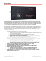
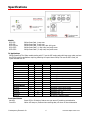
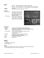
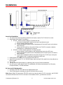
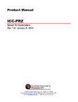
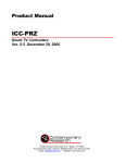
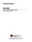
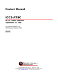
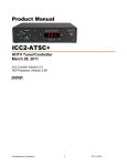
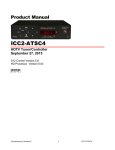
Product Manual ICC-PSC/PSC2 Philips Smart Card Controllers Ver. 1.1 January 31, 2014 17630 Davenport Road, Suite 113 • Dallas, TX 75252 Phone:972-931-2728 • Toll-Free: 888-972-2728 • Fax: 972-931-2765 E-Mail: [email protected] • Website: www.crwww.com Table of Contents Overview ............................................................................................................................................. 3 Specifications ..................................................................................................................................... 4 Models ............................................................................................................................................... 4 TV Applications ................................................................................................................................... 4 Front Panel Status ............................................................................................................................... 4 Physical.............................................................................................................................................. 5 Mounting ............................................................................................................................................ 5 Connections ........................................................................................................................................ 5 Includes ............................................................................................................................................. 5 Options .............................................................................................................................................. 5 Installation ......................................................................................................................................... 6 Smart Card Installation ........................................................................................................................ 6 RF Coax and iCC-Net Operation ............................................................................................................ 6 Using the IC-RC Remote for On-Screen Menus ....................................................................................... 7 Philips Previous Channel ...................................................................................................................... 7 On-Screen Setup Menus ....................................................................................................................... 7 RS-232 Control Protocol ..................................................................................................................... 8 Overview............................................................................................................................................ 8 Command String Structure ................................................................................................................... 8 RS-232 Commands ............................................................................................................................. 9 RS-232 Responses ............................................................................................................................ 12 Response String Structure ...................................................................................................................12 iC-Net SmartZones ........................................................................................................................... 14 System Map ...................................................................................................................................... 15 Typical RF and ICC-Net Signal Flow ................................................................................................. 16 Safety Instructions ........................................................................................................................... 17 Limited Warranty and Disclaimer ..................................................................................................... 18 Contemporary Research Co 2 ICC-PSC Philips Smart Card Overview Contemporary Research offers a simple solution for intelligent television control and interactive distributed media management, the PSC Philips Smart Cards. The ICC2-PSC communicates bi-directionally over the same RF coax that carries the CATV channels, while the ICC1-PSC receives 1-way commands over RF. Older Philips “P” series require the PSC-series cards, newer Philips TVs use the low-profile PSC2-series cards. All PSC cards take advantage of Philips SmartCard TV technology. Inserting into the SmartCard card slot, the PSC cards use the TV's internal IR sensor, character generator, and tuner to deliver cost-effective network TV and media management. The cards are available optionally with external S-Video and composite AV input connections (shown above). Controls Philips SmartCard TVs for cost-effective operation o Creates on-screen channel labels, messages interactive text menus, and system feedback using TV’s onboard character generator o Receives wireless commands from IC-RC IR remote using TV’s IR sensor o Delivers absolute volume control for level and mute o Manages channel access using list of available channels (tuning ring) in controller memory o Delivers absolute power control with on/off feedback from TV Interacts with Philips SmartCard TV’s internal IR sensors, character generator, and tuner Networks with up to 4,000 TVs through the ICC-HE or ICW-HE Head-End Network Controller (HE) o ICC1 units receive commands over the same RF cable as CATV channels o ICC2 units provide 2-way command and control with feedback over RF o ICC2 units transmits key commands from IC-RC remote for 2-way control applications o Exclusive SmartZone architecture controls hundreds of controllers with a single command Responds to individual and zone commands from a single RS-232 port on the HE Provides LED feedback for network, control, and operation status Restores all operation status after loss of power from data stored in non-volatile memory Installs in Philips SmartCard slot on back of TV o PSC-series cover plates fit older Philips “P” series TVs, AV inputs optional on card o PSC2-series cover plates fit newer low-profile Philips TVs, AV inputs included on TV Updates firmware over iCC-Net network via modem or Internet (ICE-HE) from factory, PC update software available 1st quarter 2004 Contemporary Research Co 3 ICC-PSC Philips Smart Card Specifications Models ICC1-PSC: ICC2-PSC: ICC2-PSC/AV: ICC1-PSC2: ICC2-PSC2: Philips Philips Philips Philips Philips Smart Smart Smart Smart Smart Card, 1-way coax Card, 2-way coax Card, 2-way coax, with A/V inputs Card 2, 1-way coax, low-profile cover Card 2, 2-way coax, low-profile cover TV Applications Philips SmartCard TVs. Older models starting with “P” use the PSC-series cards with large cover plate, and use the PSC/AV card for applications requiring switching AV inputs. Newer Philips TVs use the PSC2 cards, AV inputs included with TV. Philips TVS New Models ST220 Series FT997 Series FW997 Series FW997 Series LT220 Series LT621 Series LW621 Series 55RW951 ST230 Series ICC-P ICC-PSC2 X X X X X X X X Previous Models PL Series PA Series PC Series PPC Series SC Series Front Panel Status Net LED: Com LED: ICC-PSC X X Notes SmartCard, 19" - 36" TV SmartCard, 15" HDTV LCD SmartCard, 17 - 30" 16:9 HDTV LCD, Iconn1 box SmartCard, 32 - 50" Plasma, Iconn2 box SmartPlug, 13"- 27" SmartPlug, 27"- 32", Flatscreen CRT SmartPlug, 30"- 34", Flatscreen, Iconn1 box 55" HDTV, Iconn1 box Do not use - ScanCard conflict SmartPlug, requires power supply SmartPlug, requires power supply SmartCard, 19" - 27" SmartCard, 32" - 36" Do not use - ScanCard conflict X X Green LED for iC-Net bus, flashes once per second if receiving communication Yellow LED stays on, flashes when receiving data, off when no Smart data active Contemporary Research Co 4 ICC-PSC Philips Smart Card Physical Size: Weight: Enclosure: Mounting ICC-PSC2 series: ICC-PSC series: PSC Card - 3.765" [95.63mm] wide x 5.585" [141.86mm] deep PSC Cover - 4.53" [115mm] wide x 3.41" [87mm] height x .58" [14.73mm] deep PSC2 Cover– 4.93" [125mm] wide x 2.41" [61mm] height x .58" [14.73mm] deep 6 oz [170g] All aluminum with durable black powder coat paint Card installs into SmartCard slot CATV connects to card RF input RF Out cable extends thru slot At bottom of card, connects to external TV RF input Card installs into SmartCard slot CATV connects to card RF input RF Out cable on card connects to internal TV RF input in card slot ICC2-PSC2 Installation Connections Cable/Ant: iCC-Net: Receive: Transmit (ICC2): AV Inputs: RF Out: Ground: Power: ‘F’, female, 75 ohm impedance, RF from CATV system Carried over the same RF coax connection as TV channels Mid-band VHF, 74.7MHz, sent from IC Head-End Network Controller -25 to +35 dBmV signal level Sub-band, 5.6MHz sent to Head-End Network Controller ± 80 KHz max carrier deviation +49dBmV nominal S-Video and mono audio RCA (ICC2-PSC/AV only) Composite RCA and mono audio RCA Internal RCA female, 75 ohm impedance, RF to TV Internal lug for TV GND wire Powered by TV Includes PSC Card Cover plate F to RCA adapter (ICC-PSC2 only) 2 RCA RF cables, 7.5” Options Internal buzzer for system alerts, closure for camera power relay (factory-installed options) IC-RC Wireless IR Remote for user control and system setup Contemporary Research Co 5 ICC-PSC Philips Smart Card Installation Smart Card Installation 1. Turn off TV and remove the existing SmartCard cover plate, requires Torx T10 driver for screws 2. Install Philips Smart Card RF connections a. ICC PSC – RF Out connects inside the TV Smart Card slot i. Disconnect the attached RF cable from the tuner input below the card. ii. Remove existing SmartCard slowly. iii. Connect included RCA cable from the Cable/Antenna RCA to the RF Input on the bottom side of the card. iv. Connect the RCA cable from the card’s RF Out to the TV’s RF In connector inside the SmartCard port, located below the card slot. b. ICC-PSC2 – RF Out connects outside the TV Smart Card slot i. Attach included F to RCA adapter to the Cable/Antenna input on the PSC cover. ii. Connect included RCA cable from the Cable/Antenna RCA to the RF Input on the bottom side of the card. iii. Connect the included RCA cable from the card’s RF Out to the TV RF input, running the cable outside to the TV’s antenna input below the PSC2 card. 3. Gently but fully insert PSC card into the Philips Smart Card slot. 4. Attach PSC cover plate to TV – for ICC-PSC2 cards, make sure the RF Out cable fits into the cable slot on the cover plate. 5. Turn on TV. 6. The Net LED should light and stay on, indicating power, but not iC-Net communication. 7. Com LED turns on when data link with TV is established; LED blinks when data sent from IR remote, front-panel buttons, or iC-Net commands. RF Coax and iCC-Net Operation 1. Connect the CATV RF Coax cable into the Cable/Antenna jack. 2. If the iCC-Net signal is operating, the Net LED will blink once per second. Note: Newer Philips TVs that use the ICC-PSC2 cards do not have an interior TV RF in connector, the ICC-PSC2 connects the RF Out to the TV’s RF In connector on the outside of the TV, just below the card slot. Contemporary Research Co 6 ICC-PSC Philips Smart Card Using the IC-RC Remote for On-Screen Menus In order to complete the setup, you’ll need the IC-RC IR Remote to use the On-Screen Menus. Typically, the remote is shipped ready to communicate to Smart TV. Just in case, here’s how to set the IR codes in the remote: 1. 2. 3. 4. Press and hold the Select button and a numeric key for the code # below. Release the two keys at the same time. The remote will now send the selected codes. Remote will keep the codes, even if battery power is lost. IR Code Format Philips Smart TV Code 2 Philips Previous Channel Some Philips models will not respond properly to the IC-RC’s PrevCh command, marked as A/CH on the Philips IR remote. If this happens, use the Philips special setup IR remote to set the A/CH A/V SWITCH menu selection to OFF. On-Screen Setup Menus The remaining installation steps use the IR remote and the TV’s built-in character generator. 1. Touch Menu, then 999, then Enter. 2. The text CR MENU> should appear on the screen. 3. Key in one of the commands shown below, then press Enter to activate. 4. Note that, in Menu mode, the Channel Down key acts as a backspace/delete key and Channel Up can act as an Enter. Command All 45678 45679 65478 65479 65487 65482 ICC2 65480 65481 65483 Function The following commands are used for all units Display firmware version Display the unit’s Device #. At this point, you can use the Channel Down key as a Delete key, enter a new device # with the remote’s numeric keypad, then hit Enter to save the new number. Reset unit, similar to disconnecting power then restarting. Disable smart port communication. After about 5 seconds the TV will drop communication with the TV controller and revert to stand alone TV mode. At this point, the installer can switch to the TV Mode on the remote control, and then adjust the TV setup parameters. To re-enable smart port, press Record on IC-RC. Initialize to factory default settings: Power on, unlocked, display channel 11, channel ring set to 4, 5, and 11, Group 0. Note that this command works even if TV power is off or control is locked out. Shows Net RX if receiving the iC-HE’s “heartbeat” pulse once per second, !NET RX if not. Also displays receive signal strength for ICC2 units. The following commands are used for the ICC2 only Enable constant Net transmit to the Head-End. This is used for measuring the signal strength of the ICC2 unit’s RF output. Press Enter to stop transmitting, or the unit will automatically stop after 50 seconds. Display ICC2 transmitter frequency control voltage – should be 2000 - 3150. Display DF transmitter frequency deviation – should be 245 - 300. Contemporary Research Co 7 ICC-PSC Philips Smart Card RS-232 Control Protocol Overview RS-232 control for up to 4000 TV Controllers is provided through an iC-series Head-End Network Controller. The ICC-HE Head-End manages iC-Net communication over RF Coax to ICC1 (1-way) and ICC2 (2-Way) TV Controllers as well as ICW TV Controllers over twisted-pair Cat3/5 wiring. The ICW-HE Head-End operates on the twisted-pair network only. Each TV Controller is assigned a unique device number from 1 to 4000 to which control commands are addressed. The devices are organized into 16 zones of 255 devices. All the devices in each zone will respond to a single “virtual device number” — one device number that represents all devices in each zone. There is also a global device number, 4095, that will command all devices in the system. This feature dramatically speeds up system operation and programming, because one command can affect an entire group of devices—or all. To take advantages of this feature, review the section iC-Net Zones in this manual. In ABC Media Retrieval Systems, we reserve the first group of devices, 1-255, for components operating on a connected control system. Zones 1-16 are used for CR TV Controllers, Video Display Controllers and Tuners. As it’s unlikely any system will use all 4000 devices, this may be a good device standard for your system as well. The Remote RS-232 port on the Head-End Network Controller can communicate from 1200 to 38.4K baud. The factory default setting is 19.2K baud, 8 data bits, No parity, and 1 stop bit. Command String Structure Characters in command strings are expressed in a combination of hex and ASCII characters. For clarity, the following protocol examples use the following conventions: Single-byte hex numbers are preceded by the ‘$’ symbol ASCII characters or strings are enclosed in single quotes Numbers not marked as hex or ASCII are a single decimal byte Parameters shown in < > brackets are single byte A series of multiple commands or parameters are set apart by [ ] brackets Commas separate the bytes, but are not part of the protocol Double quotes enclose the command string, but are not part of the protocol Command format: “$A5,<dh>,<dl>,<ncb>,<cmd1>,<parameter> [<cmdN>]" $A5 <dh> <dl> <ncb> <cmd1> <parameter> [<cmdN>] Starts the command The zone or high order byte of the device The unit or low order byte of the device (0 for global zone) The number of command bytes to follow The first command byte Command parameters (not used by all commands) Multiple commands can be concatenated, with byte count added to <ncb> Contemporary Research Co 8 ICC-PSC Philips Smart Card RS-232 Commands Command Power Off P0 Description “$A5,<dh>,<dl>,2,’P0’ ” (6 bytes) – checks TV data for true power control Power On P1 “$A5,<dh>,<dl>,2,’P1’ ” (6 bytes) – checks TV data for true power control Power Toggle PT “$A5,<dh>,<dl>,2,’PT’ ” (6 bytes) – checks TV data for true power control Operating Parameters TM “$A5,<dh>,<dl>,3,’TM’,<setting>” (7 bytes) Sets up key functions in the unit Bit 7 – 3 = 0 Bit 2 – Channel up/down operation, 0=Tune Ring, 1=Send IR Keypad response Bit 1 – Numeric channel labels, 0=num labels off, 1=num labels on) Bit 0 – Alpha channel labels, 0=alpha labels off, 1=alpha labels on Volume VL “$A5,<dh>,<dl>,3,’VL’,<vol level>” (7 bytes) Sets TV volume level 0 = Mute 1 – 63 = Minimum level (1) to maximum volume (63) Ts & Qs T-series channel commands select a channel and display the channel label on the TV, while Q-series commands don’t show the on-screen text. T Channel Up TU “$A5,<dh>,<dl>,2,’TU’ ” (6 bytes) – Tunes to next channel up in Tune Ring T Channel Dwn TD “$A5,<dh>,<dl>,2,’TD’ ” (6 bytes) – Tunes to next channel down in Tune Ring T Channel Prev Force T Channel TP TC “$A5,<dh>,<dl>,2,’TP’ ” (6 bytes) – Tunes to previous channel in Tune Ring “$A5,<dh>,<dl>,3,’TC’, <channel>” (7 bytes) – Tunes to a specific channel 124 = 125 = 126 = 127 = 0= 255 = RGB 2 input on TV RGB input on TV Select TV composite A/V input Select S-Video Input Blank video output to TV Unblank TV video (restore to previous channel) Select T Channel TT Tip: Not all inputs are available on every TV make and model “$A5,<dh>,<dl>,2,’TT’ <channel>” (7 bytes) – Tunes channel if included in TR Channel Query T? “$A5,<dh>,<dl>,2,’T?’ ” (6 bytes) – Request response for current channel Q Channel Up QU “$A5,<dh>,<dl>,2,’QU’ ” (6 bytes) – Tunes to next channel up in Tune Ring Q Channel Dwn QD “$A5,<dh>,<dl>,2,’QD’ ” (6 bytes) – Tunes to next channel down in Tune Ring Q Channel Prev Force Q Channel QP QC “$A5,<dh>,<dl>,2,’QP’ ” (6 bytes) – Tunes to previous channel in Tune Ring “$A5,<dh>,<dl>,3,’QC’, <channel>” (7 bytes) – Tunes to a specific channel Select Q Channel QT Same special-function channels as in the T Channel Select section above “$A5,<dh>,<dl>,2,’QT’,<channel>” (7 bytes) – Tunes channel if included in TR Contemporary Research Co 9 ICC-PSC Philips Smart Card Command Tune Ring Description TR “$A5,<dh>,<dl>,<ncb>,’TR’, [<chan 1>, <chan N>]” (variable bytes) This command stores a Tune Ring, a series of preset channels accessed by channel up/down commands. Ex1: “$A5,<dh>,<dl>,6,’TR’, 5,4,8,11” sets ring to channels 5, 4, 8 and 11 Tip: The ring follows the stored order, channels do not have to be in ascending order Ex Ex2: “$A5,<dh>,<dl>,2,’TR’ ” clears the Tune Ring, locks unit to current channel Tip: In the above mode, the IR Keypad channel up/down response to the HeadEnd, so the system will know the user is trying to change channels. In response, the system could change channels on a media sources, like a VCR or satellite. (Feature not provided in 1-way models). Channel Labels Ex3: “$A5,<dh>,<dl>,8,’TR’, $82,5,$87,11” sets channels 2-5 and 7-11. You can specify a range using MSB bit for the first channel; the next byte is the last. TN “$A5,<dh>,<dl>,<ncb>,‘TN’,<channel>,<label>” (variable bytes) Stores an ASCII string as the channel label. The text will appear briefly when the channel is selected, if the feature has been activated by Setup command (TM). Display Label Ex1: “$A5,<dh>,<dl>,6,‘TN’, ‘7’, ‘PBS’ ” TV displays PBS when 7 is selected Ex2: “$A5,<dh>,<dl>,3,‘TN’, ‘7’ ” Clears alpha label for channel 7 Ex3: “$A5,<dh>,<dl>,4,‘TN’,0,0” Clears all alpha labels TC “$A5,<dh>,<dl>,2,’TC’ ” (6 bytes) – Display current channel label for about 15 sec. Closures Y- “$A5,<dh>,<dl>,3, ‘Y’ <I/0 Port>’ ” (7 bytes) Factory option only Turns the two internal closures on and off. Closure 1 is typically used to control the optional buzzer, Closure 2 typically used to control an external camera power relay. Control Lock Device Status “$A5,<dh>,<dl>,3, ‘Y10’” turns Closure 1 off “$A5,<dh>,<dl>,3, ‘Y11’” turns Closure 1 on “$A5,<dh>,<dl>,3, ‘Y20’” turns Closure 2 off “$A5,<dh>,<dl>,3, ‘Y21’” turns Closure 2 on LM “$A5,<dh>,<dl>,3,'LM',<control>” (7 bytes) Locks out front panel and IR remote control functions. (0=enabled, 1=disabled) Bit 7 Selects IR remote control operation, except vol Bit 6 Selects volume control operation Bit 5 Always 0 Bit 4 Deletes Tune Ring in internal TV memory Bit 3-1 Always 0 Bit 0 Selects TV front panel buttons operation except vol SP "$A5,0,0,3,'SP'" (6 bytes) 2-way units only Queries the Head-End for the number of devices present on the network and the number of devices expected. (Not provided in 1-way units) Contemporary Research Co 10 ICC-PSC Philips Smart Card Command Write Text DM Description “$A5,<dh>,<dl>,<ncb>,‘DM’, <start line>,<text color>,<background color>, <background>,<size and shadow>,<timeout>,<message bytes>” (variable bytes) Clears current text, displays text message over video (normal) or blank background. The built-in character generator can accept up to 40 characters of text (including carriage returns), 28 characters per line. Use a hex $0D or decimal 13 in the text as a carriage return, which will advance CG to the next line, first space on the right. Start Line - 1-11 Text Color - 1-7= White Text Background Color – 0-7=Transparent (no background) Full screen background – 0=normal insert over video, 1=blank screen (blue) Size and Shadow – 0-3=small text with drop shadow Time-Out – 0=15-second display, 1=persistent Persistent text stays on screen until the next DM command a new Menu or channel is selected. Ex1: “$A5,<dh>,<dl>,10,‘DM’, 2,7,0,0,1,0,’TEST’ ” displays the word TEST on the second line, white text, inserted over video, small size with drop shadow, and timing out after 15 seconds. Ex2: “$A5,<dh>,<dl>,2,‘DM’ ” clears on-screen display, also clears persistent text Contemporary Research Co 11 ICC-PSC Philips Smart Card RS-232 Responses Two-way iC-Net devices will send a response over the network whenever there is there is a change in status or command from an IR remote or front panel. Response String Structure Characters in response strings are expressed in a combination of hex and ASCII characters. For clarity, the following protocol examples use the following conventions: ASCII characters or strings are shown enclosed in single quotes Numbers shown that are not in single quotes are a single decimal byte Parameters shown in < > brackets are single byte A series of multiple commands or parameters are set apart by [ ] brackets Commas separate the bytes, but are not part of the protocol Double quotes enclose the command string, but are not part of the protocol Command format: “ ‘<’,<dh>,<dl>,<nrb>,<rb1>, <para1> [<rbN>]" ‘>’ <dh> <dl> <nrb> <rb1> <para1> [<rbN>] Response New Channel Starts the response The zone or high order byte of the device The unit or low order byte of the device (0 for global zone) The number of response bytes to follow The first response byte Associated parameters, if any Multiple responses may be included T Description “ ‘<’,<dh>,<dl>,2,'T',<new channel>" (6 bytes) Sends in response to T? command. IR Function F “ ‘<’,<dh>,<dl>,2,'F',<IR Function>" (6 bytes) Sent when unit receives a new function command is pressed (1-8) or released (0) from the IR remote. 0 1 2 3 4 5 8 = = = = = = = Contemporary Research Co Release Play Stop Pause Fast Forward Rewind Record 12 ICC-PSC Philips Smart Card Response IR Key K Description “ ‘<’,<dh>,<dl>,2,'K',<IR Key>" (6 bytes) Sent when unit receives a new key command is pressed (10-116) or released (0) from the IR remote. 0 = Release 10 - 19 = Numeric keypad entry 0 – 9 21 = Enter 22 = Channel Up 23 = Channel Down 29 = Menu 101 = Previous Channel IR Menu M 105 106 107 108 109 110 116 = = = = = = = Media Menu Cursor Right Cursor Left Cursor Up Cursor Down Media Select Timer The 0 – 9, Channel Up/Down functions are sent only if enabled in the TM command (Bit 2 = 1). The Channel Up/Down responses will be sent if the Tune Ring contains no channels – see Ex2 in the Tune Ring command section. “ ‘<’,<dh>,<dl>,5,'M',<msh>, <msl>, <mph>, <mpl>" (9 bytes) Sent when unit receives a new Menu command is pressed or released (0) from the IR remote. Menu Selection high and low bytes are in <msh> and <msl>. Menu Parameter high and low bytes are in <mph> and <mpl>. A Menu command is initiated by pressing the Menu key, followed by a numeric entry, then the Enter or Channel Up key. During the Menu process, the Channel Down key acts as a backspace or delete key. Some selections that need only a single numeric entry and will have a parameter value of zero (0). Those keys are 0, 8, 9, 18, 20, 30, 900, 911, and 912. Menu selections that will prompt the user to enter a second parameter entry are: 1 = Select Media 2 = Password 3 = Chapter Search 4 = Frame Search 11 = Channel 21 = Page Zone 22 = Page Room 25 = Go 21 = Attach Zone 32 = Attach Room Device Response Tip: The Menu entries are active even if the TV power is off. SP " '<',0,0,4,'SP',<number devices present>,<number devices expected> (8 bytes) Sent in response to HE status query. Tip: If the number of present and expected devices match, the green Net LED on the HE will blink once per second. If the two numbers do not agree, the LED blinks twice per second. Contemporary Research Co 13 ICC-PSC Philips Smart Card iC-Net SmartZones To simplify controlling groups of devices, iC-Net is divided into 16 zones of 255 devices, called SmartZones. All the devices within each zone can be controlled simultaneously by sending a command to a single virtual device number. For example, noting the zone chart below, if we send a Power On command to device #256, any TV controller numbered between 257 and 511 will instantly turn on. If we send a Power Off command to device #4095, all devices in the system will turn off. This is an immensely powerful feature, because most systems can only address one device at time. So if you need to turn off all 50 TV in a zone, you would need to send 50 commands. In addition to the hassles of creating multiple commands, there would be a long delay between the first and last command. One command, instant response is easier. As we noted before, ABC Media Retrieval Systems reserve Zone 0 for devices used in the central control system, 1 -15 for iC-Net devices. This structure may be useful for your application, or you could use Zone 0 just like any other iC-Net zone. Zone 1 2 3 4 5 6 7 8 9 10 11 12 13 14 15 All Zones Tip: First Device 257 513 769 1025 1281 1537 1793 2049 2305 2561 2817 3073 3329 3585 3841 Last Device 511 767 1023 1279 1535 1791 2047 2303 2559 2815 3071 3327 3583 3839 4000 Virtual Device 256 512 768 1024 1280 1536 1792 2048 2304 2560 2816 3072 3328 3584 3840 4095 You've probably figured out that you never want to assign a virtual device number to an actual device in the system. If you assigned #1536 to a device, all the TV controllers in Zone 6 would respond every time you sent a command to that one device. Contemporary Research Co 14 ICC-PSC Philips Smart Card System Map One of the key tasks for iC-Net integrators is to create a logical System Map, assigning device numbers to TV controllers so they fall into logical zones. The device mapping could be sorted by type or location; whichever suits the application. iC-Net Zone 1 2 3 4 Zone W 1st Floor W 2nd Floor E 1st Floor E 2nd Floor Room 256 W151 W152 W153 W154 1793 1794 1795 1796 2048 Office Contemporary Research Co 1537 1538 1792 Hallways All 1281 1282 1283 1536 Day Care Admin A/V Center All Zones 1025 1024 1025 1026 1280 Coffee Areas W1 W2 E1 E2 8 769 770 771 772 1024 TV 1 TV 2 7 513 514 515 516 768 E151 E152 E153 E154 G100 G150 G151 6 257 258 259 260 512 W251 W252 W253 W254 E251 E252 E253 E254 5 Device 2049 2050 4095 15 ICC-PSC Philips Smart Card Typical RF and ICC-Net Signal Flow The diagram below shows the structure of a typical Contemporary Research media retrieval system. One of the key aspects for iCC-Net communication is to provide a forward and return (sub-channel) path for data if you’re using ICC2 2-way TV Controllers. Contemporary Research Co 16 ICC-PSC Philips Smart Card Safety Instructions Read before operating equipment. 1. Cleaning - Unplug this product from the wall outlet before cleaning. Do not use liquid cleaners or aerosol cleaners. Use a damp cloth for cleaning. 2. Power Sources - Use supplied or equivalent UL/CSA approved low voltage DC plug-in transformer. 3. Outdoor Antenna Grounding - If you connect an outside antenna or cable system to the product, be sure the antenna or cable system is grounded so as to provide some protection against voltage surges and built-up static charges. Section 810 of the National Electrical Code, ANSI/NFPA No. 70, provides information with respect to proper grounding of the mast and supporting structure, grounding of the lead-in wire to an antenna discharge unit, size of grounding conductors, location of antenna discharge unit, connection to grounding electrodes, and requirements for the grounding electrode. 4. Lightning - Avoid installation or reconfiguration of wiring during lightning activity. 5. Power Lines - Do not locate an outside antenna system near overhead power lines or other electric light or power circuits or where it can fall into such power lines or circuits. When installing an outside antenna system, refrain from touching such power lines or circuits, as contact with them might be fatal. 6. Overloading - Do not overload wall outlets and extension cords as this can result in a risk of fire or electric shock. 7. Object and Liquid Entry - Never push objects of any kind into this product through openings as they may touch dangerous voltage points or short out parts, resulting in a fire or electric shock. Never spill liquid of any kind on the product. 8. Servicing - Do not attempt to service this product yourself as opening or removing covers may expose you to dangerous voltage or other hazards. Refer all servicing to qualified service personnel. 9. Damage Requiring Service - Unplug this product from the wall outlet and refer servicing to qualified service personnel under the following conditions: When the power supply cord or plug is damaged. If liquid spills or objects fall into the product. If the product is exposed to rain or water. If the product does not operate normally by following the operating instructions. Adjust only those controls that are covered by the operating instructions. An improper adjustment of other controls may result in damage and will often require extensive work by a qualified technician to restore the product to its normal operation. If the video product is dropped or the cabinet is damaged. When the video product exhibits a distinct change in performance, this indicates a need for service. * Note to CATV system installer: This reminder is provided to call CATV system installer's attention to Article 820-40 of the National Electrical Code (Section 54 of Canadian Electrical Code, Part I), that provides guidelines for proper grounding and, in particular, specifies that the cable ground shall be connected to the grounding system of the building as close to the point of cable entry as possible. Contemporary Research Co 17 ICC-PSC Philips Smart Card Limited Warranty and Disclaimer Contemporary Research Corporation (CR) warrants this product to be free from defects in material and workmanship under normal use for a period of two years from the date of purchase from CR. Should such a defect occur CR will repair or replace, at their option, the defective product at no cost for parts or labor. This warranty extends to product purchased directly from CR or an Authorized CR Dealer. Consumers should inquire from selling dealer as to the nature and extent of the dealer's warranty, if any. All warranty claims must be shipped pre-paid to the factory. Call or fax to obtain a Return Material Authorization (RMA) number. CR is not liable for any damages caused by any of its products or for the failure of any products to perform, including any lost profits, lost savings, incidental damages, or consequential damages. CR is not responsible for any claim made by a third party or made for you by a third party. This limitation of liability applies whether damages are sought, or a claim is made, under this warranty or as a tort claim (including negligence and strict product liability), a contract claim, or any other claim. This limitation of liability cannot be waived or amended by any person. This limitation of liability will be effective even if CR or an authorized representative of CR has been advised of the possibility of any such damages. Some states do not allow a limitation of how long an implied warranty lasts. Some states do not allow the limitation or exclusion of incidental or consequential damages for consumer products. In such states, the limitation or exclusion of the Limited Warranty may not apply to you. This Limited Warranty gives you specific legal rights. You may also have other rights that may vary from state to state. You are advised to consult applicable state laws for a full determination of your rights. Except as expressly set forth in this Limited Warranty, CR makes no other warranties, expressed or implied, including any implied warranties of merchantability or fitness for a particular purpose. CR expressly disclaims all warranties not stated in this Limited Warranty. Any implied warranties that may be imposed by law are limited to the terms of this Limited Warranty. Contemporary Research Co 18 ICC-PSC Philips Smart Card