1
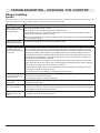
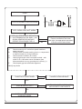
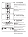
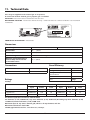
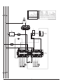
AlberTine 90 Dual Fuel Range
Service Instructions
AlberTine
AlberTine
This book contains many important safety messages.
Always read and obey all safety messages.
Installer : Leave these instructions with the range.
Important - Save the installation instructions for the local electrical
inspector’s use.
F107150-02
Contents
Troubleshooting
3
Servicing Notes
7
1 To change an oven lightbulb
8
2 To move range for servicing
8
3 To remove the oven door
8
4 To remove the cooktop
9
5 To remove a control panel
9
6 To remove an outer side panel
10
7 To remove an oven neon
10
8 To change oven light switch
10
9 To remove thermostat
10
10 To change a multifunction oven function switch
11
11 To remove a cooktop valve
11
12 To change a cooktop burner FSD
11
13 To change an ignition switch
11
14 To remove a cooktop burner orifice
12
15 To remove a cooktop burner spark
12
16 To remove a cooktop burner
12
17 To change the oven outer door panel and door trims
12
18 To replace a door inner panel
13
19 To remove the oven door seal
13
20 To remove the cooktop spark generator
13
21 To remove the cooktop electrode leads
13
22 To remove oven inner back
14
23 To replace an oven fan
14
24 To remove an oven fan element
14
25 To remove left hand multifunction oven bottom and top elements
14
26 To change the cooling fan
15
Technical Data
16
Schematic diagram of the range
17
TROUBLESHOOTING - CHECKING THE OVEN
Check
Result
One bulb does not
work
Possible Cause
Light bulb failed (most likely cause)
No power to range
Open the oven door and turn on the oven lights
Action
Fault in power supply to switch on facia
Faulty switch
In line switch problem
Remove the light bulb. Check the bulb resistance with a meter and replace it if necessary.
If the bulb is OK then move the range forward and remove the rear cover.
With the meter check the continuity of the wiring to the bulb and the action of the switch. Replace wiring or switch
as necessary.
Check
Result
Turn the function control to the Defrost setting
and check that the oven fans start to spin.
Action
Both lights do not
work
Fan(s) do not spin
Possible Cause
Fault in power supply to switch
Faulty switch
Fault in power supply to fan
Fan motor faulty
Fan blades impeded
Remove the oven inner back and check that the fan is not impeded.
If not then move the range forward and remove the rear cover.
With the meter check the continuity of the wiring to the fan and the action of the switch. Replace wiring, switches
or fan as necessary.
Check
Remove the oven racks. Turn the oven
temperature control to 400F and turn the function
control to each setting in turn and check that the
elements start to heat up. See the chart opposite.
You should be able to feel the heat from the
element after few moments by holding your
hand close to the element (DON’T TOUCH THE
ELEMENTS!).
The bottom elements may take slightly longer to
heat up.
Turn the controls off when you have finished.
Result
One element does not
heat up
Possible Cause
Burnt out element (most likely cause)
Faulty switch
Fault in power supply to element
Faulty oven thermostat (most likely cause)
No element heats up
Faulty switch
Fault in power supply to elements
Action
One element not working
Remove the element and check it with a meter. Replace with a new element if necessary.
If the element is OK then move the range forward and check the continuity of the wiring
and the function switch.
3
No element working
Remove the range cooktop
and check the thermostat and
function switch
TROUBLESHOOTING - CHECKING THE OVEN
ArtNo.280-116 - MF Knob Symbols
��������������
��������
��������������
���������
����������
���������
���������
�������
����������������
���������������
ArtNo.280-0117 - MF Oven Element Servicing
�����������������
�������������������
������������������������
���������
��������
Base Heat
Base element only
Convection Broiling
Fan(s) plus both the
top elements.
Browning Element
Inner element in the
top of the oven only.
Fan Assisted Oven
Fan(s) plus outer
element at the top
and the base
element.
Conventional Oven
Outer top element
and the base element
- no fan(s).
Defrost
Fan(s) only. No heat
is applied.
Convection Assisted
Oven
Fan(s) and the
heating element
around it.
4
TROUBLESHOOTING - CHECKING THE COOKTOP
Range Cooktop
Ignition
The maintop burners have spark ignition operated by a switch on each control valve. When any burner control knob is pressed
in the spark generator module produces sparks at all the burners ignition electrodes.
Problem
Check
Try lighting the burner with a match.
The ignition system
makes sparks but does Are the flames even around the head with a blueish color?
not light the gas
Check the burner head is clean and the flame ports are clear. Check that the burner head is
sitting down correctly on the burner base.
What gas is being used? The range is supplied set for Natural Gas. It must be converted before
it can be used on LP gas.
The ignition system
does not make sparks
Use flow chart (page 6) to check out the ignition system.
The burner lights but
the flame goes out
when the control knob
is released
Each burner gas control valve includes a thermoelectric solenoid flame safety valve (FSD)
that is normally closed. There is a sensor probe mounted on each burner. To light a burner
the user must push in the control knob and turn to the full on position. Pushing in the knob
overrides the safety valve and allows gas to flow to the burner while the knob is pushed in.
The spark ignition lights the burner and the flame heats the sensor probe. When it gets hot
enough the sensor produces a very low voltage electric current that keeps the safety valve
open when the control knob is released.
Try holding the knob in for longer. The FSD should hold in after a few seconds, if it does not
hold in after 10 seconds the sensor may not be getting hot enough because there is problem
with the burner head or the sensor position is incorrect.
Check the burner head is clean and the flame ports are clear. Check that the burner head is
sitting down correctly on the burner base.
If this does not solve the problem try changing the sensor probe.
The burner flame goes Check that the burner control valve is fitted with the correct bypass screw. See the ‘Technical
Data’ section at the end of this book.
out when the control
is turned to low
Try changing the bypass screw for a new one.
The burner flames are
very yellow
What gas is being used? The range is supplied set for Natural Gas. It must be converted before
it can be used on LP gas.
The burner flames are
very small and blue
What gas is being used? The range is supplied set for Natural Gas. If it has been converted for
use on LP gas it must be reconverted by changing the burner orifices and control valve bypass
screws before it can be used on Natural Gas.
The pattern of flames
on the burner is not
even
Check the burner head is clean and the flame ports are clear. Check that the burner head is
sitting down correctly on the burner base.
5
START
PUSH IN BURNER CONTROL KNOB
CLEAR
CLEAR
ELECTRODE DOES NOT SPARK
CHECK NO RESISTANCE BETWEEN
L1 ON TERMINAL BLOCK AND L1 ON
SPARK GENERATOR MODULE.
REPEAT PROCEDURE FOR L2.
YES
A.
B.
C.
D.
E.
NO
Correct any wiring faults.
Ensure connections are clean
and tight. Use appropriate procedure
to check control valve switch.
Check continuity of h.t wire from spark module to
spark electrode.
Visually check for spark tracking from h.t. components
to earthed metal (e.g. fixing brackets).
Check ceramic insulation for cracks.
Unplug high tension wire from spark module - with
meter on�Ω x 100 scale ensure resistance from
disconnected wire to any ground point is infinity (∞).
Check spark gap and electrode alignment.
Rectify any faults.
DOES ELECTRODE SPARK
YES
CHANGE SPARK MODULE
NO
DOES BURNER LIGHT?
YES
NO
IGNITION SYSTEM NOW IN
WORKING ORDER
6
CHECK GAS SUPPLY TO RANGE
AND BURNER COMPONENTS
SERVICING - WARNING
Disconnect from electricity and gas before servicing. Check range is safe when you have finished.
Servicing Notes
When servicing or replacing gas carrying components
disconnect from gas before commencing operation and
check range is gas sound after completion. When checking
for gas leaks use a liquid leak detector at all joints and
connections to check for leaks in the system. Use a product
specifically manufactured for leak detection. Leak testing
of the range shall be conducted in accordance to the
manufacturer’s instructions.
CAUTION: DO NOT USE A FLAME TO
CHECK FOR GAS LEAKS.
When using test pressures greater than ½ psig (3.5kPa)
to pressure test the gas supply system of the residence,
disconnect the range and individual shut-off valve from
the gas supply piping. When using test pressures of ½
psig (3.5kPa) or less to test the gas supply system, simply
isolate the range from the gas supply system by closing the
individual shut-off valve.
Do not use re-conditioned or unauthorised gas controls.
Disconnect from electricity supply before commencing
servicing, particularly before removing any of the following:
control panel, side panels, cooktop tray, or any of the
electrical components or cover boxes. Before electrical
reconnection make sure the range is electrically safe.
7
1
Fig. 1-1
To change an oven light bulb
Turn off the power at the circuit breaker.
Make sure the oven is cool. Open the oven door and remove
the oven racks.
Unscrew the bulb cover by turning counter clockwise. It may
be very stiff Fig.1-1.
Taking care to protect your fingers in case the bulb should
shatter, unscrew the old bulb.
�������������������������������
Screw in the new bulb, screw back the bulb cover. Turn on the
circuit breaker and check that the bulb now lights.
Fig. 2-1
Replacement bulb must be 15w 125-130v lamp, FOR OVENS,
heat resistant to 300°C (570°F).
ArtNo.341-0001 - 90SC - Drawer pulled forward
2
To move range for servicing
Follow these procedures to move the range for servicing:
Shut off the gas supply and disconnect electrical supply to
appliance. Disconnect gas supply tubing to appliance and
unplug the electrical supply cord. (Note: These areas may be
more easily accessible once the storage drawer is removed).
Fig. 2-2
ArtNo.281-0017 - Removing the door
NOTE: A qualified person should disconnect and reconnect
the gas supply.
The range is very heavy. Please assess any risks associated
with moving. You may require a protective floor covering to
prevent any possible damage. Ensure that the floor covering
is firmly attached to prevent it being disturbed when moving
the range around. You will need the levelling tool.
ArtNo.281-0139 - Drawer clip lift
Fig. 3-1
Pull the drawer out to its furthest point and empty it Fig. 2-1.
Lift up the ends of the plastic clips (one each side) to release
the catches holding the drawer to the side runners and at the
same time pull the drawer forward and away from the side
runners Fig. 2-2.
For safety’s sake push the drawer runners back out of the way.
Put the drawer somewhere safe - do not refit it until you have
finished, you will need access to the area behind the drawer.
3
Fig. 3-2
To remove the oven door
To remove the door, open the door fully. Swivel the locking ‘U’
clips forward to the locking position Fig. 3-1. To remove the
oven door, grip the sides of the door, lift upwards and then
slide the door forward Fig. 3-2.
�������������������������������������������
When you have removed the oven door, continue as follows:
Lower the two rear rollers.
First use the levelling tool to turn the hexagonal adjusting
nut and make 10 complete 360° turns clockwise. (This means
turning and removing the levelling tool 20 times) Fig. 3-3.
Fig. 3-3
Make sure you lower BOTH REAR ROLLERS. There are two
adjusting nuts, one for each roller, at both the front bottom
corners of the range.
ArtNo.010-0010 Lowering the rear rollers (90)
The appliance can be lifted/moved by gripping the top of the
oven cavity once the door is removed.
Do not replace the storage drawer yet.
x10
8
With your hands griping under the control panel slide, the
range forward to disengage from the anti-tip bracket. Do not
pull the range by the handrail.
Fig. 3-4
Reverse procedure to reinstall. If gas line has been
disconnected, check for gas leaks after re-connection.
NOTE: A qualified person should disconnect and reconnect
the gas supply.
The service engineer MUST follow installation instructions
provided with the gas appliance connector and the warning
label attached to the connector.
ArtNo280-0085 Refitting Drawer
CAUTION: DO NOT USE A FLAME TO CHECK FOR GAS LEAKS.
Fig. 3-5
When using test pressures greater than ½ psig (3.5kPa)
to pressure test the gas supply system of the residence,
disconnect the range and individual shut-off valve from
the gas supply piping. When using test pressures of ½
psig (3.5kPa) or less to test the gas supply system, simply
isolate the range from the gas supply system by closing the
individual shut-off valve.
ArtNo.280-0021 - Drawer Locking
If the range is removed for any reason, make sure the anti-tip
device is re-engaged properly when the range is replaced.
Failure to take this precaution could result in tipping of the
range and cause injury.
Fig. 4-1
Replace the storage drawer
To replace the drawer in the range, pull the side rails fully out
Fig. 3-4. Carefully move the drawer back between the rails
and rest it on the side rails. At each side hold the front of the
drawer and pull the side rail forward so that the clips click
into position holding the drawer to the side rails Fig. 3-5.
4
ArtNo281-0109 Burner Venturi
To remove the cooktop
Fig. 4-2
Disconnect the range from the electricity supply.
Remove cooktop grids and burner heads Fig. 4-1.
Undo the large brass nuts and remove the brass venturis
using a 22mm socket Fig. 4-2. Lift up the front of the cooktop
top and disconnect the ignition leads from the electrodes
and earth lead. Lift the cooktop clear of the range. Replace in
reverse order.
5
To remove the control panel
Fig. 5-1
Remove all the control knobs. Open oven door. Remove the
4 screws on oven beak. Remove the 3 screws on the control
panel underside and 3 screws on the top front. Pull the
control panel forward Fig. 5-1.
Remove the connections from the rear of the neon and light
switch. Lift the panel clear of the range.
Replace all parts in reverse order.
When replacing any electrical connections refer to the wiring
diagram.
9
6
Fig. 6-1
To remove an outer side panel
Disconnect the range from the electricity supply. Remove the
control panel. Remove the plinth, 3 screws.
Undo the lower retaining screw situated below the edge
at the panel front corner. Remove the side panel retaining
screw on the upper front edge and the two fixings on the rear
or the side panel. Remove the panel by pulling it away from
the range Fig. 6-1.
7
To remove an oven neon
Remove the control panel.
Remove the relevant neon connections and undo the nut
which secures the neon to the control panel Fig. 7-1.
������������������������
Fig. 7-1
Replace parts in reverse order. Ensure the replacement neon
functions correctly.
8
����������������������
To change oven light switch
Remove control panel.
NB The old switch may be destroyed during removal.
Fig. 8-1
Remove switch button and old switch from its bezel by
gripping the switch body behind the control panel and
twisting sharply. The switch bezel can then be removed by
folding back its locking wings and pushing forward Fig. 8-1.
Fit the new bezel to the control panel by first lining up the
raised key on its body with the cutout in the control panel
and pushing it in from the front. Assemble the new switch to
the bezel by lining up the key sections and pushing home. Fit
the new button by pushing in from the front.
ArtNo281-0015 rear of switch
Fig. 9-1
Replace control panel in reverse order and test for correct
operation.
�����
9
To remove a thermostat
Note: Two thermostats are used in the oven. One is a primary
thermostat, which controls the oven temperature and can
be adjusted by the customer using the control knob. The
maximum housing temperature limit for this thermostat is
T120 (UL) and has an oven control temperature limit of 475ºF.
The other is a protection thermostat to prevent the oven
overheating if the primary oven thermostat should fail. The
maximum housing temperature limit for this thermostat is
T120 (UL) and the safety cut off temperature is 622ºF +/50ºF.
ArtNo.281-0116 - Oven Thermostat Phial
The protect thermostat only operates if the primary
thermostat has failed.
a) To change the primary thermostat:
Remove the cooktop.
Remove the control panel.
Remove the oven shelves.
Undo the range rear cover screws and covers.
Track the route of the thermostat capillary from the rear of
the control on the facia to where it disappears into the oven.
By moving the capillary it will become obvious which of the
two phials in the oven it is connected to. The phial can be
removed by loosening the p-clips Fig. 9-1.
Feed the thermostat capillary out and clear of the oven
noting the routing.
10
Remove the two screws fixing the thermostat to the inner
control panel and disconnect the wiring from the thermostat.
Fit the replacement in reverse order.
Ensure the phial is clipped securely to the oven rear cover.
Fig. 11-1
b) To change the protect thermostat follow the same
procedure as above except that the control is situated on the
rear cover.
10
To change a multifunction oven function
switch
ArtNo.281-0119 - Removing a cooktop valve
Move the range away from the wall - see ‘How To Move the
Range for Servicing’ (page 8).
Fig. 11-2
Remove the cooktop grates, cooktop accessories and burner
heads. Undo the large brass nuts and remove the brass
venturis and washers. Lift up the front of the cooktop top and
prop it up.
Remove the control panel.
Remove the fixing screws from the front of the Multifunction
oven function switch, disconnect the leads and remove the
switch. Fit the new switch.
11
ArtNo.281-0120 - Removing a cooktop 2
To remove a cooktop valve
Fig. 12-1
Remove the cooktop and control panel.
Unplug the FSD lead from the rear of the valve Fig. 11-1.
Undo compression fitting at the rear of the valve. Remove the
fixings that secure the valve to the gas rail Fig. 11-2.
Disconnect the ignition switch wiring.
Remove the valve. Remove and discard the gasket seal. Fit
new gasket seal to replacement valve.
ArtNo.281-0121 - Removing the brass venturi
Re-assemble in reverse order. Check the range is gas sound.
Check cooktop ignition.
12
Fig. 12-2
To change a cooktop burner FSD
Move the range away from the wall - see ‘How To Move the
Range for Servicing’ (page 8).
ArtNo.281-0117 - FSD probe fixing nut
Remove the cooktop grates, cooktop accessories and burner
heads. Undo the large brass nuts and remove the brass
venturis and washers. Lift up the front of the cooktop top and
prop it up.
Unplug the hotplate FSD from the back of the burner control
valve Fig. 12-1.
Remove the nut holding the nut holding FSD probe to the
burner mounting cross member Fig. 12-2.
Fit the new FSD probe, plug into the back of the control valve.
Reassemble in reverse order and check for correct burner
operation.
13
To change an ignition switch
Change the cooktop control valve.
11
14
Fig. 14-1
To remove a cooktop burner orifice
Disconnect the range from the electricity supply.
�����������������
������������
Remove pan support and burner head. Undo the large brass
nut and remove the brass venturi. Lift up the burner base and
disconnect the ignition lead from the electrode. The orifice is
now accessible using a 7mm box spanner.
Alternatively, remove the cooktop. Remove the orifice directly
from the burner body. Fit the appropriate orifice Fig. 14-1.
������
Re-assemble in reverse order. Check the range is gas sound.
ArtNo.281-0128 - Burner support bracket
15
Fig. 15-1
To remove a cooktop burner spark
electrode
Disconnect the range from the electricity supply. Remove the
cooktop grids, cooktop accessories and burner heads.
Undo the bezel venturi and remove the bezel from the
cooktop. The spark ignition wire will be pulled through the
electrode clearance hole Fig. 15-1. Disconnect the spark
electrode from the ignition wire.
ArtNo.281-0118 - Electrode spring
Note
Take care to prevent the ignition wire from falling back
through the clearance hole. Undo the spark electrode from
the bezel by removing the spring clip and spring. Fit the
replacement electrode to the burner bezel. Ensure that the
spring and clip are properly located. Replace in reverse order
and check correct burner ignition.
Fig. 16-1
16
To remove a cooktop burner
Remove the cooktop grids, cooktop accessories and burner
heads. Remove the cooktop.
Fig. 17-1
Remove the nut that secures the burner body to the support
channel. Remove the fixings that secure the support channel
to the chassis. Lift the channel clear of the range Fig. 16-1.
ArtNo.281-0129 - Cooktop
burner orifice assy
Undo the compression fitting which connects the burner
body to the gas pipe. Remove the burner body from the
range.
Replace in reverse order. Check the range is gas sound and
that the burner operates satisfactorily.
17
������������������������������
To change the oven outer door panel
or door trims
The door outer panel and all the trim parts are available as
separate spares so that individual parts can be changed.
Door is very heavy - take care.
Unscrew the door handle and remove the handle and door
trim handle disk Fig. 17-1.
�������������������������������
12
Place the outer panel on a clean flat surface.
Fig. 17-2
The door trim handle plate is held in place by screws on the
inside. Studs and nuts hold the other trims Fig. 17-2.
Replace the damaged parts and re-assemble in reverse order.
18
To replace a door inner panel
The door inner panel is supplied.
Remove the door.
Carefully place the door, outer side up, on a clean level
surface. Remove the hexagon headed screws.
19
To remove the oven door seal
Fig. 19-1
Open oven door. The seal is held in place by small hooks to
the range front. At the corner pull seal diagonally away from
the door centre until that hook is released.
Proceed to the next hook and release it in a similar way, and
so on. Use force if the hooks are stiff, as the old seal will be
discarded.
When fitting new seal, position the seal join at the bottom.
Hook the new seal in one of the corner holes of the door, and
proceed round the door snapping in each hook in turn
Fig. 19-1.
20
To remove the cooktop spark generator
Remove cooktop. Unclip the spark generator by first sliding
right then lift left hand side and pull forward. Remove the
wiring ensuring the wires are assembled in the same position
in new generator Fig. 20-1.
21
ArtNo.281-0017 - Removing the door
Fig. 20-1
To remove the cooktop electrode leads
Remove the cooktop grids, cooktop accessories and burner
heads.
Lift up the front of the cooktop and prop it up.
Disconnect the leads at the electrodes and generator. Replace
with new leads.
Re-assemble in reverse order and check ignition.
�����������������������������
13
22
Fig. 22-1
To remove oven inner backs
Open the oven door. For the right hand side unscrew the 4
thermostat phial fixing screws Fig. 22-1.
Remove the fixings that secure the inner back to the oven
rear. Lift the removable panels away.
Re-assemble in reverse order. Ensure that the retaining fixings
are fully tightened.
23
To replace an oven fan
Disconnect the range from the electricity supply.
Fig. 23-1
Pull the range forward to access the cover boxes at the rear
of the range, see the section ‘How To Move the Range for
Servicing’ (page 8).
Remove the inner back.
Hold the fan blades and undo the centre nut (LH thread),
brass washers, fan blade and circlip Fig. 23-1.
Undo the screws that retain the fan and remove it from the
cavity rear.
��������������������������
Fig. 24-1
Fit the replacement and re-assemble parts in reverse order.
Check that the oven operates satisfactorily.
ArtNo 281-0149 - USA oven fan element
24
To remove an oven fan element
Disconnect the range from the electricity supply.
Remove the inner back.
Remove the screws that secure the element within the oven
and lift the element away carefully Fig. 24-1.
Disconnect the leads and connect to the replacement
element and re-assemble parts in reverse order.
Fig. 25-1
25
To remove the left hand
multifunction oven bottom and
top elements
Disconnect the range from the electricity supply.
Bottom Element
Pull the range forward to access the cover boxes at the rear
of the range, see the section ‘How To Move the Range for
Servicing’. Remove the fixings that secure the cover and lift it
clear.
�����������������������������������
Fig. 25-2
Remove the 2 screws ‘A’ and allow the plate to drop down.
Remove the 2 screws B, lower the upper plate and remove
through the slot in the range back Fig. 25-1.
Undo the terminal connections, noting their positions.
Remove the element fixings and withdraw element. Replace
the element and re-assemble parts in reverse order.
���������������������������������
Top Element
Remove the top element bracket fixings and withdraw
elements carefully lifting to clear the clips on the support bar
Fig. 25-2.
Replace the element and re-assemble parts in reverse order.
Check that the oven operates satisfactorily.
14
26
To change the cooling fan
Fig. 26-1
Remove the cooktop (see section 4).
Remove the two screws on the centre rail Fig. 26-1. You can
then lift this panel to gain access to the fan.
Remove the cooling fan access panel Fig. 26-2. Disconnect
the wiring from the left hand side of the fan.
Remove the screws that hold the cooling fan to the duct
Fig. 26-3. The fan can then be lifted to be removed.
Re-assemble in reverse order.
Fig. 26-2
������������
Fig. 26-3
���������������������������������
15
11. Technical Data
This range is supplied set for natural gas 4” wc presure.
A conversion kit from natural gas to propane gas is included.
INSTALLER: Please leave these instructions with the user.
DATA BADGE LOCATION: Inside base drawer of cavity - remove drawer. For removal of drawer see installation
instructions.
���������
�������������������������
����
ArtNo.280-0090 - Drawer cavity & badges
COUNTRY OF DESTINATION: USA/Canada
Dimensions
Overall height
minimum 35
15/16” (91cm)
Overall width
35
1/2”
Overall depth
28
5/8”
Space for fixing
see “Position the Range’.
Minimum space between the top
of the cooktop and a horizontal
combustable surface.
311/2” (80cm)
(90cm)
(72.5cm)
Connections
maximum 36
7/8”
(93.7cm)
Oven Efficiency
Gas
Electric
1/2” NPT at rear left hand side
240V 60Hz
Oven
Ratings
Energy Efficiency Class
A
Energy consumption based on
standard load
0.90kWh
Useable volume (cubic foot)
3.8
Size
Large
Cooktop
Natural Gas 4” WC
Propane Gas 10” WC
Input
Orifice
Screw
Input
Orifice
Screw
Centre Burner
17,500btu/hr
205
82
17,500btu/hr
118
49
Large Burners
12,000btu/hr
150
70
12,000btu/hr
99
38
Right Hand Front Burner
6,000btu/hr
112
53
6,000btu/hr
68
31
Gas burner inputs based on Gross Calorific Value
Fan elements (2 off) 1800W each, Top outer elements (2 off) 750W each, Browning top inner elements (2 off)
1150W each, Bottom elements (2 off) 750W each.
Maximum input at any time is fanned grill, which is all top elements and fan.
Maximum total electric load 240V
3850W (approximate total inc. oven fans etc.) 16 amps.
16
17
�
��
��
���
�
�
�
�
�
�
��
�����������
�
�
�
�
�
�
�
��
�
��
�
�
��
��
�����
��
�����
�
�
�
�
��
�
�
�����
�
�
�
�
�
�
�
�
�
�
�
�
�
��
��
�
�
�����������
�
�����
�����
ArtNo.080-0023 - LC Albertine 36 USA circuit diagram
�
�
��
��
��
�
��
�
�����
��
��
��
��
�
��
�
�
�
�
�
��
�����
�
�
�
�����
��
�
��
�
�
�����
�����
���
������
������
�����
����
���������������
������������
�����
���������
��
��
�
�
�
�
��
������
������
�
�����
�
�
�
�
�
�
�
�
�
�
�
�
�
�
�
�
�
�
�
�
�
�������������������
����������������������
�����������������
��������������������
��������������������
��������������
������
�����������
�����������������
��������������������
��������������������
��������������
������
�����������������
���������
����������
����������
�����������������
���������������
��������������
������������
���� �����������
������
����
�
��
��
18
19
ArtNo280-0093 Back Cover Bar
��


![U109969-03 - 900S Falcon Albertine [NL-DE] (Sep](http://vs1.manualzilla.com/store/data/006803119_1-3e5bc5b7002fe08f8a32bb7db1ca8572-150x150.png)