1
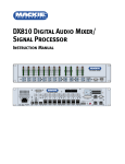
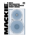
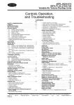
INSTRUCTION MANUAL
DX810 v3.3
8x10 Digital Matrix Mixer and Signal Processor
OL
OL
OL
OL
OL
OL
OL
2
4
7
10
15
20
25
30
35
40
50
2
4
7
10
15
20
25
30
35
40
50
2
4
7
10
15
20
25
30
35
40
50
2
4
7
10
15
20
25
30
35
40
50
2
4
7
10
15
20
25
30
35
40
50
2
4
7
10
15
20
25
30
35
40
50
2
4
7
10
15
20
25
30
35
40
50
OL
15
12
9
6
3
2
4
7
10
15
20
25
30
35
40
50
0
3
6
9
12
15
DX810 DIGITAL MIXER
A
1
2
3
4
5
6
7
8
LO
EQ
HI
A
MASTER
B
LOCK
MODE
B
POWER
COMM PORT
1 2 3 4 5 6 7 8
SERIAL NUMBER
MANUFACTURING DATE
– +
DX810 DIGITAL MIXER
U
U
U
U
U
U
U
U
U
U
C GAIN
MI
C GAIN
MI
C GAIN
MI
C GAIN
MI
C GAIN
MI
C GAIN
MI
C GAIN
MI
C GAIN
MI
60
0
-30dB +30dB
60
0
-30dB +30dB
60
0
-30dB +30dB
60
0
-30dB +30dB
60
0
-30dB +30dB
60
0
-30dB +30dB
60
0
-30dB +30dB
60
0
-30dB +30dB
TRIM
TRIM
TRIM
TRIM
TRIM
TRIM
TRIM
TRIM
MIC
MIC
MIC
MIC
MIC
MIC
MIC
MIC
G
12
-20
+20
TRIM
BUS A
POWER
INPUT
22-28V DC,
3A MAX
100 – 240V
R
, 50/60Hz, 1A MAX
LISTED COMMERCIAL
AUDIO EQUIPMENT
9Z39
–
-20
+20
TRIM
BUS B
MIC
+ G
LINE
G +
1
2
3
4
5
6
7
8
–
G 11
INPUTS
OUTPUTS
I
+ –
C
H
G
A
LINE
LINE
LINE
LINE
LINE
LINE
LINE
G
1
B
1 2 3 4 5 6 7 8
LINE
D
1 +5V
+
E
F
–
REMOTE BUS
COMM PORT
OUTPUTS
ON
LINE
J
LOGIC I/O
PHANTOM POWER
48V DC
–
+
LINE
G
•10e
DIRECT OUTPUTS
RECORD
A
G
+
–
B
G
+
–
CAUTION
WARNING — To reduce the risk of fire or
electric shock, do not expose this appliance to
rain or moisture.
AVIS
RISK OF ELECTRIC SHOCK • DO NOT OPEN
RISQUE DE CHOC ELECTRIQUE
NE PAS OUVRIR
CAUTION: TO REDUCE THE RISK OF ELECTRIC SHOCK
DO NOT REMOVE COVER (OR BACK)
NO USER-SERVICEABLE PARTS INSIDE
REFER SERVICING TO QUALIFIED PERSONNEL
ATTENTION: POUR EVITER LES RISQUES DE CHOC
ELECTRIQUE, NE PAS ENLEVER LE COUVERCLE. AUCUN
ENTRETIEN DE PIECES INTERIEURES PAR L'USAGER. CONFIER
L'ENTRETIEN AU PERSONNEL QUALIFIE.
AVIS: POUR EVITER LES RISQUES D'INCENDIE OU
D'ELECTROCUTION, N'EXPOSEZ PAS CET ARTICLE
A LA PLUIE OU A L'HUMIDITE
The lightning flash with arrowhead symbol within an equilateral triangle is
intended to alert the user to the presence of uninsulated "dangerous voltage"
within the product's enclosure, that may be of sufficient magnitude to constitute
a risk of electric shock to persons.
Le symbole éclair avec point de flèche à l'intérieur d'un triangle équilatéral est
utilisé pour alerter l'utilisateur de la présence à l'intérieur du coffret de "voltage
dangereux" non isolé d'ampleur suffisante pour constituer un risque d'éléctrocution.
The exclamation point within an equilateral triangle is intended to alert the user
of the presence of important operating and maintenance (servicing) instructions
in the literature accompanying the appliance.
Le point d'exclamation à l'intérieur d'un triangle équilatéral est employé pour
alerter les utilisateurs de la présence d'instructions importantes pour le fonctionnement et l'entretien (service) dans le livret d'instruction accompagnant l'appareil.
Table of Contents
1. SAFETY INSTRUCTIONS ............................................................... 2
2. INTRODUCTION .............................................................................. 3
Key Features ................................................................................. 4
Front Panel Features ..................................................................... 5
Rear Panel Features ..................................................................... 5
3. INSTALLATION ................................................................................ 7
Connections .................................................................................. 7
AC Power Considerations ............................................................. 8
4. OPERATION .................................................................................... 9
Quick Start .................................................................................... 9
Using Inputs 1-8 ......................................................................... 10
Using the BUS A and B Inputs .................................................... 10
Using the DIRECT OUTPUTS ....................................................... 11
Using OUTPUTS A Through J ..................................................... 11
Using the RECORD Output .......................................................... 11
Using the REMOTE Controls ....................................................... 11
Using the LOGIC I/O ................................................................... 11
Password Protection ................................................................... 13
5. DX-810-PC SOFTWARE (v 3.3) .................................................... 13
Installing the Software ............................................................... 13
Upgrading the Software ............................................................. 13
Connecting a PC ......................................................................... 14
Upgrading the Firmware ............................................................. 14
Overview .................................................................................. 14
Top Section ................................................................................. 15
Menu Bar ............................................................................... 15
Indicators/Presets/Control ..................................................... 18
Button Section ....................................................................... 19
Crosspoint Matrix Section .......................................................... 26
Input Section .............................................................................. 27
Output Section ............................................................................ 27
Group Section ............................................................................. 28
Exclusive Enable Program Selection ...................................... 28
6. SPECIFICATIONS .......................................................................... 29
DX810 Block Diagram ................................................................. 29
DX810 Specifications ................................................................. 30
7. SERVICE INFORMATION ............................................................. 32
Appendix A: Logic Input Functions ................................................... 33
Appendix B: Logic Output Functions ................................................. 33
Appendix C: Selection Remote Predefined Functions ...................... 34
Appendix D: Level Remote Predefined Functions ............................. 35
2 – DX810
CAUTION — Internal lithium battery. Danger
of explosion if battery is incorrectly replaced.
Replace only with the same or equivalent type.
1. SAFETY INSTRUCTIONS
1.
Read Instructions — Read all the safety and operation instructions before
operating the DX810.
2. Retain Instructions — The safety and operating instructions should be
kept for future reference.
3. HEED ALL WARNINGS — Follow all warnings on the DX810 and in these
operating instructions.
4. FOLLOW ALL INSTRUCTIONS — Follow all operating and other
instructions.
5. Water and Moisture — Do not use the DX810 near water – for example,
near a bathtub, washbowl, kitchen sink, laundry tub, in a wet basement,
near a swimming pool, etc.
6. Ventilation — This DX810 should be situated so that its location or
position does not interfere with its proper ventilation. For example, it
should not be situated on a bed, sofa, rug, or similar surface that may block
any ventilation openings, or placed in a built-in installation such as a
bookcase or cabinet that may impede the flow of air through ventilation
openings.
7. Heat — Locate the DX810 away from heat sources such as radiators, or
other devices which produce heat.
8. Power Sources — Connect the DX810 to a power supply only of the type
described in these operation instructions or as marked on the rear panel. If
using an external DC power supply or battery pack, be sure the voltage
corresponds to the range indicated on the rear panel, and that it is
connected with the correct polarity.
9. Power Cord Protection — Route power supply cords so that they are not
likely to be walked upon or pinched by items placed upon or against them,
paying particular attention to cords at plugs, convenience receptacles, and
the point where they exit the DX810.
10. Object and Liquid Entry — Do not drop objects into or spill liquids into the
inside of the DX810.
11. Damage Requiring Service — The DX810 should be serviced only by
qualified service personnel when:
A. The power-supply cord or the plug has been damaged; or
B. Objects have fallen, or liquid has spilled into the DX810; or
C. The DX810 has been exposed to rain; or
D. The DX810 does not appear to operate normally or exhibits a marked
change in performance; or
E. The DX810 has been dropped, or its chassis damaged.
12. Servicing — The user should not attempt to service the DX810 beyond
those means described in this operating manual. All other servicing should
be referred to the EAW Commercial Service Department.
13. To prevent electric shock, do not use this polarized plug with an extension
cord, receptacle or other outlet unless the blades can be fully inserted to
prevent blade exposure.
Pour prévenir les chocs électriques ne pas utiliser cette fiche polariseé
avec un prolongateur, un prise de courant ou une autre sortie de courant,
sauf si les lames peuvent être insérées à fond sans laisser aucune pariie à
découvert.
14. Grounding or Polarization — Precautions should be taken so that the
grounding or polarization means of the DX-810 is not defeated.
15. This apparatus does not exceed the Class A/Class B (whichever is
applicable) limits for radio noise emissions from digital apparatus as set
out in the radio interference regulations of the Canadian Department of
Communications.
ATTENTION —Le présent appareil numérique n’émet pas de bruits
radioélectriques dépassant las limites applicables aux appareils
numériques de class A/de class B (selon le cas) prescrites dans le
règlement sur le brouillage radioélectrique édicté par les ministere des
communications du Canada.
2. INTRODUCTION
The DX810 is our popular DX8 stereo digital audio
mixer with the DX10e Expansion Kit installed. This
adds eight more balanced outputs and converts it
into a powerful matrix mixer/processor. It is
designed for use in a variety of installations such as
churches, courtrooms, convention centers, and
hotels. With eight inputs, ten outputs, and a toolbox
full of DSP, the DX810 fits most any installed sound
reinforcement application.
Each of the 10 outputs represents a discrete mix
of the eight inputs, resulting in a true 8x10 mixing
matrix with virtual faders at each crosspoint. It has
the ability to group any combination of gain
elements to one of 32 groups.
A new software interface provides intuitive
setup and operation via a PC. 31-band third-octave
graphic or eight-band parametric EQs are available
on each output. There is also a three band
sweepable high and low shelving EQ with a fully
parametric mid-range control on each input.
The processing power provided by the DX810
permits inserting a gate on each input, as well as a
compressor on each input and output. It also
permits inserting signal delay on each output, and
creating crossover groups with custom high, low, or
bandpass filters applied to each output. Up to five
outputs can be assigned to a crossover group.
Each of the eight input channels is terminated to
two Phoenix-type detachable connectors. Each
connector is optimized to accept either microphone
or line-level signals. Microphone preamplifiers
employ XDR™ technology to offer studio-class
audio performance. Phantom power of 48 VDC is
switchable individually on each input. Two auxiliary
line-level inputs with trim are provided, allowing
analog signals to be mixed with the A and B master
mixes. All main outputs deliver balanced line-level
signals to detachable Phoenix-type connectors. The
main A and B outputs also deliver buffered
unbalanced signals to RCA connectors intended for
recording.
The DX810 offers an intuitive front panel user
interface for the A and B outputs. It consists of
dual-function LED bar graph meters for each input
and the A and B outputs. Input meters indicate the
presence of signal before signal processing (pre-
fader). Output meters indicate the actual level at
output (post-fader). Levels are set by means of UP/
DOWN pushbuttons dedicated to each input and
output. A MODE button is used to select between
Mix A and B. This allows adjustment of levels to
both mix outputs from the same set of input
controls. A third function of the MODE button
allows the user to LOCK the front panel controls
until a security unlock code is entered.
The DX810 offers flexible interface options
through dedicated inputs and outputs for control
and programming purposes. Two independent
RS232 connectors are provided, one on the front
panel and one on the rear, for connection to a
computer or control system. A multi-pin (DB25F)
connector on the rear panel allows interface among
the 10 Logic Inputs and 10 Logic Outputs. This
interface connects to switches, LEDs, and other
devices, enabling hardware control and indication
from custom control panels. All logic inputs and
outputs are programmable in software. A
proprietary remote control bus allows connection of
the optional wired remotes over three-conductor
cable. Remotes are available in Volume Control
(DX-RVC) and 4-Switch (DX-SW4) versions and may
be combined in any configuration.
The DX810 is supplied with DX-810-PC software
that allows access to all of the system’s settings
and configurations. The software provides access to
the 3-band input EQ, 31-band graphic EQ, eightband parametric EQ, compressors, gates, delays,
and crossover configuration. Group assignments
and room combining are also configured in the
software application. In addition, it allows saving
and recalling up to 24 presets, configuration for
input force on/force off functions with priority, and
for the logic input and output connections. All
settings and text labels are retained in the DX810,
and can be saved on the computer’s local drive.
The DX810 is UL and CE approved and designed
for continuous use in professional fixed installation
systems. An internal auto-ranging power supply
allows connection to mains voltages from 90-240
VAC at 50/60 Hz. This is without requiring jumper or
switch setting changes. A 24 VDC input is provided
for applications where backup power is required.
Switchover to backup power is automatic and silent.
Part No. SW0096 Rev. A 01/04
© 2004 LOUD Technologies Inc. All Rights Reserved.
DX810 – 3
Preview Limit Reached! To view more of this manual,
please visit:
http://freemanualdownload.com/EAW-DX810-free-manu
al-download