1
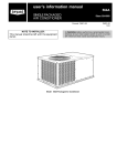
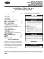
48AJ,AK,AW,AY020-060
with Reciprocating Compressor
48EJ,EK,EW,EY024-068
Single Package Rooftop Units
Electric Cooling/Gas Heating
Installation, Start-Up and
Service Instructions
CONTENTS
Page
SAFETY CONSIDERATIONS . . . . . . . . . . . . . . . . . . . . . . 1
INSTALLATION . . . . . . . . . . . . . . . . . . . . . . . . . . . . . . . . 1-58
Step 1 — Provide Unit Support . . . . . . . . . . . . . . . . . . . 1
• ROOF CURB
• ALTERNATE UNIT SUPPORT
Step 2 — Rig and Place Unit . . . . . . . . . . . . . . . . . . . . . 2
• POSITIONING
• ROOF MOUNT
Step 3 — Field Fabricate Ductwork . . . . . . . . . . . . . . . 2
Step 4 — Make Unit Duct Connections . . . . . . . . . . . 2
Step 5 — Install Flue Hood . . . . . . . . . . . . . . . . . . . . . . 28
Step 6 — Trap Condensate Drain . . . . . . . . . . . . . . . . 28
Step 7 — Install Gas Piping . . . . . . . . . . . . . . . . . . . . . 28
Step 8 — Controls Options . . . . . . . . . . . . . . . . . . . . . . 29
• STAGED GAS UNIT APPLICATIONS
• THERMISTORS
• CONSTANT VOLUME APPLICATIONS
• VARIABLE AIR VOLUME (VAV) APPLICATIONS
Step 9 — Make Electrical Connections . . . . . . . . . . 33
• POWER WIRING
• FIELD POWER SUPPLY
• FIELD CONTROL WIRING
Step 10 — Make Outdoor-Air Inlet
Adjustments . . . . . . . . . . . . . . . . . . . . . . . . . . . . . . . . . . 48
• ECONOMIZER
• ECONOMIZER SETTINGS
Step 11 — Position Power Exhaust/Barometric
Relief Damper Hood. . . . . . . . . . . . . . . . . . . . . . . . . . . 52
Step 12 — Install All Accessories . . . . . . . . . . . . . . . 54
Step 13 — Field Modifications. . . . . . . . . . . . . . . . . . . 57
START-UP . . . . . . . . . . . . . . . . . . . . . . . . . . . . . . . . . . . . 58-89
SERVICE . . . . . . . . . . . . . . . . . . . . . . . . . . . . . . . . . . . . 89-102
TROUBLESHOOTING. . . . . . . . . . . . . . . . . . . . . . . 103-115
START-UP CHECKLIST . . . . . . . . . . . . . . . . . . . CL-1,CL-2
SAFETY CONSIDERATIONS
Installation and servicing of air-conditioning equipment can
be hazardous due to system pressure and electrical components. Only trained and qualified service personnel should install, repair, or service air-conditioning equipment.
Untrained personnel can perform the basic maintenance
functions of cleaning coils and filters and replacing filters. All
other operations should be performed by trained service personnel. When working on air-conditioning equipment, observe
precautions in the literature, tags and labels attached to the unit,
and other safety precautions that may apply.
Follow all safety codes. Wear safety glasses and work
gloves. Use quenching cloth for unbrazing operations. Have
fire extinguishers available for all brazing operations.
Before performing service or maintenance operations on
unit, turn off main power switch to unit. Electrical shock
could cause personal injury.
1. Improper installation, adjustment, alteration, service,
or maintenance can cause property damage, personal
injury, or loss of life. Refer to the User’s Information
Manual provided with this unit for more details.
2. Do not store or use gasoline or other flammable vapors and liquids in the vicinity of this or any other
appliance.
What to do if you smell gas:
1. DO NOT try to light any appliance.
2. DO NOT touch any electrical switch, or use any
phone in your building.
3. IMMEDIATELY call your gas supplier from a neighbor’s phone. Follow the gas supplier’s instructions.
4. If you cannot reach your gas supplier, call the fire
department.
Disconnect gas piping from unit when pressure testing at
pressure greater than 0.5 psig. Pressures greater than
0.5 psig will cause gas valve damage resulting in hazardous
condition. If gas valve is subjected to pressure greater than
0.5 psig, it must be replaced before use. When pressure
testing field-supplied gas piping at pressures of 0.5 psig or
less, a unit connected to such piping must be isolated by
closing the manual gas valve(s).
INSTALLATION
Step 1 — Provide Unit Support
1. All panels must be in place when rigging.
2. Unit is not designed for handling by fork truck.
Manufacturer reserves the right to discontinue, or change at any time, specifications or designs without notice and without incurring obligations.
PC 111
Catalog No. 534-739
Printed in U.S.A.
Form 48A,E-1SI
Pg 1
107
11-01
Replaces: 48E-6SI
Book 1
Tab 1a
When unit is located adjacent to public walkways, flue assembly must be at least 7 ft above grade.
ROOF MOUNT — Check building codes for weight distribution requirements. See Fig. 17. Unit operating weight is shown
in Table 2.
ROOF CURB — For vertical discharge units, assemble or install accessory roof curb in accordance with instructions
shipped with this accessory. See Fig. 1-4. Install insulation,
cant strips, roofing, and counter flashing as shown. Ductwork
can be installed to roof curb before unit is set in place. Curb
should be level. This is necessary to permit unit drain to function properly. Unit leveling tolerance is shown in Fig. 1-3.
Refer to Accessory Roof Curb Installation Instructions for
additional information as required. When accessory roof curb
is used, unit may be installed on class A, B, or C roof covering
material.
Step 3 — Field Fabricate Ductwork — Secure all
ducts to building structure. Use flexible duct connectors between unit and ducts as required. Insulate and weatherproof all
external ductwork, joints, and roof openings with counter
flashing and mastic in accordance with applicable codes.
NOTE: Due to width of the horizontal supply/return ductwork,
provisions should be made for servicing of the outdoor air filters (i.e., catwalk over ductwork).
Ducts passing through an unconditioned space must be insulated and covered with a vapor barrier. Outlet grilles must not
lie directly below unit discharge. The return duct must have a
90-degree elbow before opening into the building space if the
unit is equipped with power exhaust.
To attach ductwork to roof curb, insert duct approximately
10 to 11 in. up into roof curb. Connect ductwork to 14-gage
roof curb material with sheet metal screws driven from inside
the duct.
IMPORTANT: The gasketing of the unit to the roof curb is
critical for a watertight seal. Install gasket with the roof
curb as shown in Fig. 1-3. Improperly applied gasket can
also result in air leaks and poor unit performance.
ALTERNATE UNIT SUPPORT — When the preferred curb
or slab mount cannot be used, support unit with sleepers on perimeter, using unit curb support area. If sleepers cannot be
used, support long sides of unit (refer to Fig. 5-16) with a minimum number of 4-in. x 4-in. pads spaced as follows:
48AJ,AK,AW,AY020-030 and 48EJ,EK,EW,EY024-034 units
require 3 pads on each side; 48AJ,AK,AW,AY035-050 and
48EJ,EK,EW,EY038-048 units require 4 pads on each side;
48AJ,AK,AW,AY060 and 48EJ,EK,EW,EY054-068 units require 6 pads on each side. Unit may sag if supported by corners
only.
For vertical supply and return units, tools or parts could
drop into ductwork and cause an injury. Install a 90-degree
elbow turn in the supply and return ductwork between the
unit and the conditioned space. If a 90-degree elbow cannot
be installed, then a grille of sufficient strength and density
should be installed to prevent objects from falling into the
conditioned space.
Step 2 — Rig and Place Unit — Inspect
unit for
transportation damage. See Tables 1A and 1B for physical data.
File any claim with transportation agency.
Do not drop unit; keep upright. Use spreader bars over unit
to prevent sling or cable damage. Level by using unit frame as
a reference; leveling tolerance is shown in Fig. 1-3. See Fig. 17
for additional information. Unit operating weight is shown in
Table 2.
NOTE: On retrofit jobs, ductwork may be attached to old unit
instead of roof curb. Be careful not to damage ductwork when
removing old unit. Attach existing ductwork to roof curb
instead of unit.
Four lifting lugs are provided on the unit base rails as shown
in Fig. 5-16. Refer to rigging instructions on unit.
POSITIONING — Maintain clearance, per Fig. 5-16, around
and above unit to provide minimum distance from combustible
materials, proper airflow, and service access.
Do not install unit in an indoor location. Do not locate unit
air inlets near exhaust vents or other sources of contaminated
air. For proper unit operation, adequate combustion and ventilation air must be provided in accordance with Section 5.3 (Air
for Combustion and Ventilation) of the National Fuel Gas
Code, ANSI Z223.1 (American National Standards Institute).
Although unit is weatherproof, guard against water from
higher level runoff and overhangs.
Locate mechanical draft system flue assembly at least 4 ft
from any opening through which combustion products could
enter the building, and at least 4 ft from any adjacent building.
Step 4 — Make Unit Duct Connections
48AJ,AK,EJ,EK UNITS — Unit is shipped for through-thebottom duct connections. Field-fabricated ductwork should be
attached to the roof curb. Supply and return duct dimensions
are shown in Fig. 5-7 and 11-13. Air distribution is shown in
Fig. 18 and 19. Refer to installation instructions shipped with
roof curb for more information.
48AW,AY,EW,EY UNITS — Remove shipping covers from
supply and return air openings. Attach field-supplied ductwork
to unit. Connect to the unit with a single duct for all supply
openings and with a single duct for all return openings. Splitting of the airflow into branch ducts should not be done at the
unit. Sufficient duct length should be used prior to branching to
ensure the air temperatures are well mixed within the ductwork. See Fig. 8-10 and 14-16 for duct opening dimensions.
Secure all ducts to building structure. Air distribution is shown
in Fig. 8-10 and 14-16.
Install accessory barometric relief or power exhaust in the
field-fabricated return ductwork. Refer to Step 11 — Position
Power Exhaust/Barometric Relief Damper Hood section on
page 52 for more information.
Instructions continued on page 28.
2
3
Fig. 1 — Roof Curb — 48AJ,AK020-030 and 48EJ,EK024-034 Units
Preview Limit Reached! To view more of this manual,
please visit:
http://freemanualdownload.com/Carrier-48AK-free-man
ual-download