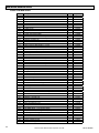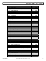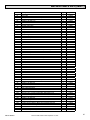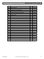
1
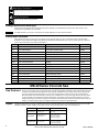
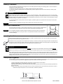
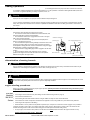
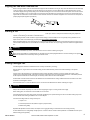
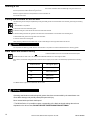
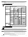
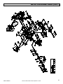
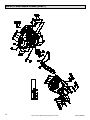
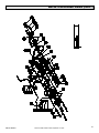
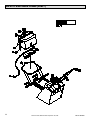
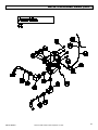
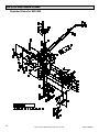
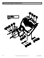
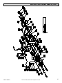
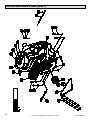
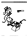
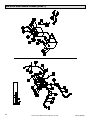
MK-20 SERIES
on
Model MK 20 Series
Owner’s Manual Parts List &
Operating Instructions
CONCRETE SAWS
20 SERIES MODELS
2013 HSP, 2013 HE,
2020 HSP
R
CAUTION:
))
((
Read Safety
And General
Instructions
Carefully
Before Using
Saw For The
First Time.
serial number
You should record the serial
number of your saw on this
owner’s manual and on the
warranty card, which must
be sent in to be effective. Be
sure to include all pertinent
information required.
Part No. 156777
Revision 09/06
Table of Contents
General Safety Instructions.......................................... 2
safety messages......................................................... 3
hazard symbols........................................................... 3
damage prevention messages.................................... 4
safety label locations................................................... 4
Saw Features................................................................. 4
blade drive system...................................................... 5
tach/ Hourmeter MK-20 Series................................... 5
water system............................................................... 5
Unpacking, Assembly and Preparation....................... 5
Initial Servicing.............................................................. 5
engine preparation...................................................... 5
add oil.................................................................. 5
add fuel................................................................ 5
Battery Preparation..................................................... 6
hydrostatic transmission............................................. 6
mounting the blade..................................................... 6
front pointer alignment................................................ 6
Sawing Operations........................................................ 7
description of controls................................................. 7
determination of sawing hazards................................ 7
operation in enclosed areas........................................ 7
engine starting procedures......................................... 7
pre start checklist MK-2013 Series...................... 7
pre start checklist MK-2020................................. 8
maneuvering the saw.................................................. 8
wet cutting................................................................... 8
dry cutting................................................................... 8
aligning the saw with a marked line............................ 9
starting a cut............................................................... 9
sawing a straight line.................................................. 9
finishing a cut............................................................ 10
cutting with the blade on the left side........................ 10
blade speed and throttle setting................................ 10
Maintenance................................................................. 11
cleaning......................................................................11
engine........................................................................11
Maintenance Schedule..............................................11
grease points............................................................ 12
controls..................................................................... 12
hydrostatic transmission........................................... 12
drive chain................................................................. 12
friction drive wheels adjustment................................ 12
neutral adjustment.................................................... 12
v-belts........................................................................ 13
electrical system........................................................ 13
battery....................................................................... 13
depth control............................................................. 13
water system............................................................. 13
Troubleshooting.......................................................... 14
Service Record............................................................ 15
Parts List MK-2013...................................................... 16
Parts List MK-2020...................................................... 22
Exploded Views for MK-2013...................................... 28
Exploded Views for MK-2020...................................... 34
General Safety Instructions
For your safety!
These safety precautions should be followed at all times. Failure to follow these safety precautions could
result in injury to yourself and others.
This manual has been prepared to provide complete instructions for operation and maintenance of the MK20 Series concrete saw. For additional instruction concerning engine operations and care refer to the engine
manufacturers instructions. Before using this equipment, ensure that the person operating this machine
has read and understands all instructions in this manual. Precaution is the best insurance against accidents.
Read and observe all safety precautions.
Revision 09/06, Effective Date September 18, 2006
MK-20 SERIES
safety messages
)
A safety message informs you about potential hazards that could hurt you or others. Each safety message is preceded by one of the
) Caution.
threeon
words: Danger, Warning, or
((
Danger
on
((
on
Warning
))
You CAN be KILLED or SERIOUSLY injured if you don’t follow instructions.
Caution
)
on
hazard symbols
Read Owner‘s Manual Before Use!
((
onusing this
Before
)) equipment, ensure that the person operating this machine has read and understands all of the instructions in the
manual. Precaution is the best insurance against accidents. Read and understand all safety precautions, messages, warnings and
hazard symbols. You are responsible for your own safety.
Keep Gaurds In Place!
))
((
onto safety guidelines: ANSI American National Standards Institute, OHSA, or local Regulations. Never operate the saw with out
Adhere
the guards in place!
))
Over Speed!
((
((
))
ontamper with the governor components or settings to increase the maximum speed. Severe personal injury and damage to the
Never
)
)
engine or equipment can result if operated at speeds above maximum.
((
Explosive Fuel!
))
on
((
Gasoline is extremely flammable and its vapors can explode if ignited. Store gasoline only in approved containers, in well-ventilated,
unoccupied buildings, away from sparks or flames. Do not fill the fuel tank while the engine is hot or running, since spilled fuel could
ignite if it comes in contact with hot parts or sparks from ignition. Do not start the engine near spilled fuel. Never use gasoline as a
cleaning agent.
))
Electrical
on Shock!
((
Never touch electrical wires or components while the engine is running. They can be sources of electrical shock which could cause
severe injury or burns.
))
Hot Parts!
((
Engine components can get extremely hot from operation. To prevent severe burns, do not touch these areas while the engine is
running or immediately after it is turned off. Never operate the engine with heat shields or guards removed.
))
Accidental Starts!
Before servicing the engine or equipment, always remove the key and disconnect the spark plug lead to prevent the engine from
starting accidentally. Ground the lead to prevent sparks that could cause fires. Make sure the equipment is in neutral.
((
on
))
Rotating Parts!
Keep hands, feet, hair, and clothing away from all moving parts to prevent injury. Never operate the engine with covers, shrouds, or
guards removed.
((
on
Lethal Exhaust Gases!
))
((
Engine exhaust gases contain poisonous carbon monoxide. Carbon monoxide is odorless, colorless, and can cause death if inhaled.
Avoid inhaling exhaust fumes, and never run the engine in a closed building or confined area.
))
Use Approved Eye Protection!
Always use approved eye protection with side shields or face shields.
((
on
((
You CAN be injured if you don’t
) follow instructions.
Additional information as to the nature of the hazard is provided by the following hazards symbols which appear throughout the
on
manual in conjunction with safety message alert symbols.
MK-20 SERIES
))
Revision 09/06, Effective Date September 18, 2006
((
on
Respiratory Protection! ))
((
Always use approved respiratory protection.
Hearing Protection!
Always use approved hearing protection.
damage prevention messages
))
((
Other important messages that are designed to help prevent damage to your MK-20 Series concrete saw, other property, or the
environment are preceded by the word notice.
notice
Your MK-20 Series concrete saw or other property could be damaged if you don’t follow instructions.
safetyonlabel locations
Safety labels are located according to the chart below and the parts list starting on page 15. The labels contain important safety
information. Please read them carefully. These labels are considered a permanent part of your saw. If a label comes off or becomes
hard to read, contact MK or your dealer for replacement.
Location
Description
Part #
C6
Top of Belt Guard
Spark Plug Caution Label
155579
C7
Front of Belt Guard
Belt Tension Caution Label
155583
C8
Top of Shaft & Belt Guard
Guards in Place Caution Label
155587
D15
Top of Blade Guard
Lift Guard Caution Label
155586
G13
Top of Console Tower
Central Control Panel
156749
G14
Back of))Console Tower
Water On/Off
154404
G15
Back of Console Tower
Engage
154405
G16
Back of Console Tower
Disengage
154406
G17
Back of Console Tower
Engine Stop
156601
L19
Top of Gas Tank
Hot Surface Caution Label
155578
L20
Top of Gas Tank
Refueling Warning Label
155580
L21
Front of Gas Tank
California Danger Label
155581
L22
Top of Gas Tank
Lethal Exhaust Danger Label
155582
M7
Front Edge of Frame
Hands and Feet Caution Label
155585
O4
Center of Handlebar
Handle Lifting Warning Label
156627
((
Item
MK-20 Series Concrete Saw
Saw Features
Engine
The MK-20 Series Concrete Saw is designed for wet or dry, high production flat and general industrial application
sawing. The heavy duty steel, one piece box frame is precision jig welded and reinforced. This precisely reinforced steel
construction with balanced weight distribution and ergonomic handlebars assures straight and accurate cutting as well
as ease of operations preventing fatigue. The 4-cycle air cooled engine is located for easy access and maintenance.
Each solid rubber wheel is mounted on an axle for years of reliable use. The rear axle is rigid, while the front axle pivots
causing the blade to be lowered to the desired cutting depth. The positive screw feed provides precision control of the
raising and lowering of the blade. The positive screw feed control wheel and all controls are located for easy access and
visibility. The following table shows the available models and the features that differentiate them.
The MK-2013HSP features a Honda ™ GX390 13 hp engine. The MK-2013HE features a Honda GX390 with electric start. The MK2020 HSP features a Honda™ GX620 20 hp engine with electric start and key ignition switch and 16” blade guard.
Model
Engine/Blade Capacity
MK-2013 HSP
cyclone air filter, tach/
hourmeter
MK-2013 HE
Honda GX390 13 hp
16” blade guard
electric starter, tach/
hourmeter, centrifugal
water pump (optional)
MK-2020 HSP
Additional Features
Honda GX390 13 hp
16” blade guard
Honda GX620 20 hp
20” blade guard
electric starter, tach/
hourmeter, centrifugal
water pump (optional)
Revision 09/06, Effective Date September 18, 2006
MK-20 SERIES
blade drive system
The blade drive shaft pulleys are connected to both the engine and to the frame mounted blade shaft. Matched v-belts are connected
to the pulleys providing engine power to the blade shaft. The one (1) inch diameter blade shaft is supported by two self-aligning pillow
block bearings. The uniquely designed right and left blade shaft allows for cutting within two (2) inches of any wall.
on
tach/ Hourmeter MK-20 Series
A digital readout tach/hourmeter is factory installed on all MK-20 Series models. When the engine is running, the display will indicate
the engines RPM. When the engine is shut off, the display will switch to run time, initially in minutes, and then switching to hours after
the first hour of operation.
water system
The water system of this saw provides water to both sides of the saw blade from inside the blade guard. The saw includes a hose bib
hookup and water flow control valve.
Unpacking, Assembly and Preparation
Your MK-20 Series has been shipped from the factory fully assembled and requires only minimal service to insure proper machine
preparation prior to use. The following instructions should be followed closely. Carefully remove carton, packing materials and the
MK-20 Series from the pallet. The
) saw has been thoroughly inspected and test operated before shipping and should not require
any additional adjustments prior to use. Check each item with the illustration making certain all items are accounted for and in good
visual condition before discarding any packing materials. If there are any missing or damaged parts, call customer service on our toll
free number: 1-(800) 421-2222 for instructions before proceeding further. CONTENTS OF CARTON: saw, wrench, engine manual,
warranty card, owners manual.
((
)
Warning
For your own safety, never start engine until all assembly steps are complete. Read and familiarize yourself with all controls and
features of this saw as shown in the illustration before beginning operations. (Descriptions and illustrations are as accurate as possible
at the time of publication. Illustrations may include optional equipment or accessories and may not show all models covered by this
literature). The handlebar and pointer assemblies are shipped in the carton without attachment to the main saw frame. Upon removal
of the saw from the carton and pallet, the handlebars should be placed in their correct mounting tube positions attached to the rear of
on Series main frame. Fasteners (3/8-16 bolts, washers, and nuts) have been placed in the plastic owners tube attached to
the MK-20
the saw with the manual. Remove these fasteners and use them to attach the handlebar and pointer assembly to the main frame as
indicated in the exploded drawing.
Initial Servicing
The engine must be thoroughly lubricated, and filled with fuel prior to break-in or use. Refer to manufactures instructions for details of
service for the engine. The section on Maintenance in this manual describes the required periodic maintenance required under normal
use.
engine preparation
notice
add
oil
The engine may be shipped with oil in the crank case. Check crankcase dipstick. To fill the crankcase with oil, place the engine level.
In order for this to be accomplished the blade must not be installed, and the depth adjustment must be down (until the engine is level).
Refer to the manufacturers instructions for details on the type and amount of oil required. Since the proper amount of oil is important
for safe operation, check the oil level of the engine each time you put fuel in the gas tank. Remember that the engine and oil must be
warm and your saw must be on level ground to get an accurate reading.
add
fuel
The engine is designed to operate on regular grade unleaded gasoline only. Adding fuel to the tank should be accomplished only
when the engine is stopped and cool. Care should be taken to prevent spilling fuel over any part of the console or engine.
((
))
Warning
In the event of a fuel spill do not attempt to start the engine until the spilled fuel has been wiped up and the area is completely dry.
When filling the fuel tank do not overfill. Always leave enough area for expansion due to environmental heating.
MK-20 SERIES
Revision 09/06, Effective Date September 18, 2006
Battery Preparation
)
((
The 12 volt battery is shipped wet and charged. Connect the battery leads accourding to the following steps to ensure that power is
)
provided to the engines electric starter.
1. Remove the front tower panel (item L17 or LA25) to obtain access to the batery terminals.
2. Connect the positive (+) battery cable to the Positive battery terminal. Tighten the cap screw and nut securely to assure proper
electrical contact.
Warning
When tightening the positive (+) battery cable end, do not contact the Negative (-) battery terminal with the wrench or other metallic
objects. This could cause an electrical short and electrical sparking or an explosion of the battery. Be careful not to connect the battery
in reverse polarity, as this will short circuit the battery charging system causing the fuse on the engine to become damaged, and also
possibly resulting in an explosion of the battery.
on
3. Connect the Negative (-) battery cable end to the negative (-) terminal. Tighten the cap screw and nut securely to assure proper
electrical contact.
notice
4. Electric power is now available for engine starting. Replace the front tower panel securely.
hydrostatic transmission
The Hydro-Static Transmission is factory filled with fluid having a viscosity equivalent to SAE 20 W 20.
Check the oil level on the expansion tank to ensure that the transmission has adequate fluid.
notice
Do not overfill the expansion tank. Notice that the full level line is near the bottom of the expansion
tank. Over filling will result in rupturing the seals on the hydromatic transmission and subsequent
mechanical damage.
O
IL
L E V E L CO
LD
mounting the blade
When mounting the blade, locate the direction arrow on the blade and install the blade in the proper orientation. The blade rotates
clockwise when viewed from the right side of the saw.
)
((
The blade must be properly fitted) over the blade shaft and drive pin. The drive pin must project through the hole in the blade and into
the flange for proper performance. When tightening the blade shaft nut against the outside of the flange, tighten securely. Blade shaft
threads are left-hand on the right side of the saw, and right-hand on the left of the saw.
WARNING
DO NOT operate without the proper blade guard covering the blade! DO NOT
operate the saw with the front of the blade guard raised. Ensure that blade exposure does not exceed 180 degrees during operation.
When installing the blade insure that the blade shaft and flanges are free of dirt and all foreign material before mounting blade on the
arbor shaft. Tightening the blade against a uneven surface can cause fracture of an abrasive blade or cause the blade to run out of
alignment, which will result in excessive blade wear. Before mounting the blade on the arbor shaft, check to be sure the shaft is not
damaged and the threads are clear of dirt and residue.
front pointer alignment
The front pointer is set in line at the factory. However, the pointer should be checked for proper alignment with the blade after every
use. The following are the procedures for aligning the pointer with the blade, with the engine shut off.
1. Using a straight edge, carefully mark a line 12 feet long on a smooth level concrete surface.
2. Place saw parallel to line. Lower blade and center it over the line.
3. With the blade centered over the line and the saw frame parallel to the line, lower the front pointer assembly and position the pointer over the line.
4. Finally, roll the saw along the entire length of the line. The saw should lead off no more than 6 inches to the left in 12 feet of forward travel. Adjust the pointer in or out if the lead-off is outside this parameter.
Revision 09/06, Effective Date September 18, 2006
MK-20 SERIES
Sawing Operations
))
((
This section of the manual describes the operating procedures, and safety precautions for proper use of this concrete saw. This saw
is intended for industrial applications by experienced operators. It is to be operated in conformance with applicable federal, state and
local codes or regulations pertaining to safety, air pollution, noise, etc.
Warning
Improper use of this equipment, or improper machine alterations may be dangerous.
It is the operators responsibility to use this machine under safe working conditions and to be fully aware of requirements for operator
onThe operator must be aware of the machine’s capabilities and limitations and follow the safety precautions in each section of
safety.
this manual.
description of controls
All controls for saw operation are located on the console.
• The raise lever wheel raises the blade when rotated clockwise, and
lowers
onthe blade when rotated counterclockwise.
• The raise/lower wheel lock is engaged when the knob on the right
raise/lower control wheel
side of the console is tightened.
• The throttle control increases engine rpm from slow (idle) at the
rpm/hour gauge
bottom, to fast (full rpm) at the top.
• The forward/reverse speed control gradually increases the saw travel
speed (up for forward, down for reverse) when moved from the central
neutral position. Always place this control in neutral before using the engage/
disengage lever or starting or stopping the engine.
• The transmission engage/disengage lever is engaged in the full down
position.
throttle
• The keyed ignition switch turns clockwise to the on and start
trans. control lever
positions. The engine turns over with the switch in the start position.
depth gauge
Release the key after the engine starts.
on/off switch
hose bibb
choke
water control lever
optional pump on/off switch
((
))
trans. engage/ disengage lever
determination of sawing hazards
Warning
Prior to operation of this machine the operator must determine the existence and location of any subsurface features which may be
hazardous or could damage the )equipment (i.e. electric cable, natural gas line, etc.).
((
)
operation in enclosed areas
Warning
The operator is cautioned not to use this equipment within enclosed spaces. Exhaust from the engine in an enclosed space can cause
serious illness and possibly death. Ensure that the space is adequately ventilated.
engine starting procedures
Refer to the engine operating manual for proper engine operation. Special precautions should be taken during the break-in period
as specified by the Engine Manual.
pre start •
checklist •
MK-2013 •
Series •
•
Check engine oil level. Add oil if low. (See adding oil under Initial servicing section on page 4).
Check fuel level. Add fuel if low.
Check cooling air intake and external surfaces of engine. Make sure they are clean and unobstructed.
Check that the air cleaner components and all shrouds, equipment covers, and guards are in place and securely fastened.
Choke engine as required for cold starting.
• Move kill switch to the on position. Grasp handle of pull start rope, and pull it out a few inches until it engages. Once pull start is engaged, pull firmly to spin engine. Once engine starts push choke control in. Allow engine to warm up for a few minutes at half throttle. All sawing is done at the correct throttle setting (see the blade speed and throttle setting table).
• To stop engine, move throttle to slow position, turn kill switch to the OFF position and wait for all engine movement to stop.
MK-20 SERIES
DO NOT TURN OFF WHILE AT FULL THROTTLE!
Revision 09/06, Effective Date September 18, 2006
pre start •
checklist •
MK-2020 •
Check engine oil level. Add oil if low. (See adding oil under Initial servicing section on page 5).
Check fuel level. Add fuel if low.
Check cooling air intake and external surfaces of engine. Make sure they are clean and unobstructed.
•
Check that the air cleaner components and all shrouds, equipment covers, and guards are in place and securely fastened.
•
Check that the transmission is disengaged and in neutral. The transmission lever must be exactly in neutral to prevent resistance which could keep the transmission from starting.
•
Pull choke: choke engine as required for cold starting.
• Turn ignition switch to start. Once engine starts push choke control in. Allow engine to warm up for a few minutes at half throttle. All sawing is done at the correct throttle setting (see the blade speed and throttle setting table.)
onstop engine, move throttle to slow position, turn key switch to the OFF position and wait for all engine movement to stop.
• To
DO NOT TURN OFF WHILE AT FULL THROTTLE!
notice
))
((
maneuvering the saw
Raise the blade as high as possible when maneuvering so that the blade will not strike the pavement.
Warning
The blade is spinning whenever the saw is running.
Raise the blade as high as possible when maneuvering so that the blade will not strike the pavement.
The speed control lever for the hydrostatic transmission is adjusted at the factory to provide approximately 40 ft/min maximum in
forward and 20 ft/min maximum in reverse with the engine running at full throttle. When maneuvering, the engine needs to be at onehalf throttle or more so that the hydrostatic transmission can operate efficiently.
When the TRANSMISSION LEVER is in NEUTRAL and the DRIVE DISENGAGE LEVER is in the ENGAGE position, the
transmission is in NEUTRAL and the wheels are locked.
)
((
To engage the transmission push) the engaging lever down on the right rear of the console cowling. To disengage the transmission
pull the engaging lever up. When the saw is manually pushed, the transmission must be disengaged. The transmission speed control
lever is located on the top of the console. This lever controls the variable forward and reverse ground speed (up to 40 feet per minute)
of the saw.
Warning
When engaging the transmission, with the engaging lever, be sure the speed control lever is at the neutral position to avoid saw
movement.
wet cutting
The water used on the blade is to provide coolant during cutting, and to flush the concrete cutting from the cut.
The water hose bibb is located below the throttle control on the left side of the saw. After connecting the water supply, turn on the
water at the source and use water valve on console to control flow of water to blade. Be sure that both sides of the blade are getting
adequate flow of water. The water control adjustment allows the operator to manually control the flow of water to the blade during all
operations.
dry cutting
Dry cutting blades have been specially designed for use with concrete saws. Ensure that the blade you are using is clearly marked for
dry cutting.
notice
When dry cutting, it is important to keep the air filter clean. Check the condition of the filter at least every four (4) hours of operation.
Clean the pre-filter (wash in soapy water and re-oil) and change the paper filter as soon as it becomes clogged. Concrete dust is very
abrasive, and will quickly damage internal engine parts, causing loss of compression and eventual engine failure.
Saw only as deep as the specifications and job conditions require. Remember airflow helps to cool the blade during dry cutting.
Cutting too deep with one pass, or exerting excessive forward or side pressure can be dangerous. Step cut in increments of 2 inches
(50 mm) or less, for the best results.
If reinforced abrasive blades are used for cured concrete it is usually better to saw only 1” deep per pass if deeper cuts are required,
cut in multiple passes.
Thinner Diamond Blades are especially advantageous when cutting dry.
Revision 09/06, Effective Date September 18, 2006
MK-20 SERIES
aligning theonsaw with a marked line
Refer to the figure below. Push the saw forward and approach the marked line at an angle. Stop when the distance from the rear edge
of the saw frame to the line (distance A) and the distance from the pointer to the line (distance B) are approximately equal. Lift the
rear wheels slightly off the ground by lifting on the handles and swing the rear of the saw around until the pointer is on the line and the
saw frame is parallel to it. Do not tilt the saw too far forward to keep the blade from contacting the concrete. The saw should now be
aligned with the marked line. Practice will fine tune this method. Critical to this method of alignment is to ensure that the saw pointer is
properly aligned (see alignment procedures).
A
B
starting a cut
With the engine running at half-throttle. Open the water valve to full open. Check to verify that the water is flowing fully. Adjust the
amount of water flowing on the blade to a desired amount.
After adjusting the flow of water increase to proper throttle setting. Lower the blade into the cut by slowly turning clockwise on the
depth control wheel. If the water supply
is interrupted, stop cutting immediately.
)
)
((
When the desired depth of cut is reached, lock the control wheel in position with the depth control locking knob. During cutting, do not
exert excessive side pressure on the handle bars to attempt to steer the saw. Use only enough pressure to follow the original marked
line.
on
Warning
on If the saw should stall for any reason, raise the blade out of the cut before restarting the engine!
When lowering the blade into a partially made cut, the blade must be perfectly aligned within the cut before starting to saw again. DO
NOT force the blade into the material by lowering the blade too fast.
sawing a straight line
The following items should be considered for best economy and efficiency in sawing:
With the water on, engine at the correct throttle setting, and the blade lowered, push the saw forward referring to the pointer
alignment.
))
((
The saw has a natural tendency to pull towards the side on which the blade is mounted. To assure straight line cutting, apply
pressure to the appropriate handle. If excessive pressure is required back off on the forward speed of the saw. If excessive pressure
is still required to make the saw travel straight, the saw may need to have the arbor shaft adjusted.
))
((
Avoid sudden corrective actions when the saw deviates from the intended line of cutting. Sudden and severe corrections can cause
the blade to be damaged or broken.
If the saw stalls in the cut, raise the blade out of the cut and check the blade shaft nut before restarting the engine.
Warning
Always raise the blade completely out of the cut before stopping the engine or turning off the water supply.
When sawing joints, be careful not to let the blade cut into the forms.
The forward speed of the saw, during cutting, should be regulated by the operator. Driving the saw too fast while cutting may cause
the front wheels to lift causing the blade to cut at uneven depths.
The three controlling factors of cutting economy are:
1. Depth of cut
2. Forward speed of the saw (with the engine at proper throttle)
3. Blade cutting ability
Experimental adjustment of these items, with respect to the aggregate being cut will result in the best cutting economy.
As new blades wear, the cutting ability usually improves. It is best to start at a slow forward speed with a new Blade and work up to a
desired cutting speed gradually.
MK-20 SERIES
Revision 09/06, Effective Date September 18, 2006
on
finishing a cut
Raise the blade out of the cut by cranking the depth control wheel counter-clockwise. Raise the blade high enough out of the cut to
clear the pavement and allow maneuvering of the saw.
Move the engine throttle to the slow position then turn the kill switch off.
Turn off the water valve.
cutting with the blade on the left side
on
Left side cutting can be easily accomplished by moving the blade guard to the left hand side of the saw belt guard using the following
steps:
1. Turn kill switch to off position.
2. Disconnect water hose from blade guard.
3. Remove shaft guard, from the left side of the saw frame and set aside.
on
4. Remove blade guard from the right side of the saw frame and reassemble on the left side of the saw belt guard.
)
) right side of the saw frame.
5. Reassemble shaft guard on the
((
6. Connect water hose to blade guard.
When attaching a blade to the left blade shaft, use the outside flange from the right side and the left side nut.
Warning
))
((
Do not operate saw with any guards removed. Turn kill switch to off position to avoid accidental starts when removing guards.
on
blade speed and throttle setting
((
))
Since diamond blades cut best at specific rim-speeds, blades of different diameters must be turned at different blade shaft rpm’s.
The MK-2013 will run either a 14 or 16” blade and the MK-2020 HSP will run a 16” through 20” blade.
Safe, efficient, economical cutting performance will occur at the engine rpm (as read on the tachometer) stipulated on the following
chart.
blade diameter 14”
set engine rpm to
16”
3200-full throttle
18”
2850-3300
20”
2550-3000
full throttle (3500)
))
((
The MK-20 Series engine shaft to blade shaft ratio is 1:.895.
Warning
Operating saw blades at rotational speeds greater than those recommended by the manufacturer can
cause blade damage and possibly subsequent personal injury.
Never exceed 3600 rpm blade shaft speed.
* The MK-20 Series, it is possible to cause overspeeding of the blade at throttle settings above those
stipulated on the above chart; DO NOT EXCEED THESE ENGINE RPM SETTINGS!
10
Revision 09/06, Effective Date September 18, 2006
MK-20 SERIES
))
Maintenance
((
Periodic maintenance including cleaning, lubrication, tensioning of drive belts, and inspection for wear and damage are routine
servicing procedures. Following the procedures as outlined in the following table can prevent serious damage or malfunctioning of the
machine and aid in preserving the useful life of saw blades.
Warning
Before servicing the saw or engine, always turn the kill switch to the off position.
on
Item performed at
every indicated hours
or interval period
whichever goes first.
Air Filter
))
maintenance
operation
every 8 hours
or daily
Check
every 4 hours
when dry
cutting
when dry
cutting
25 hours
or weekly
100 hours or
seasonal
Change air
filter
((
on
Maintenance Schedule
Hydrostatic
Transmission
reservoir
Check oil
Blade
shaft
bearings
Mainframe
lube blade
shaft bearings
at end of
operations
Pivot
Bearings
Chain Drive
Adjust
tension
Transmission
control
Assemblies
Battery
V-Belts
replace
check water
level
Battery
((
Engine
)) Definitive information on engine maintenance is contained in
the or Honda Engine Manual provided separately. Perform all
maintenance procedures as recommended by the Engine Manual.
Warning
Shut off the engine before performing any maintenance. If the engine must be run after a maintenance operation make sure the area
is well ventilated. The exhaust contains poisonous carbon monoxide gas! Exposure can cause loss of consciousness and may result in
death.
cleaning
Clean the machine daily being careful to remove cutting dust and slurry from the blade guard engine cooling fan and air ducts. Failure
to perform this operation may prevent smooth control of the saw. Steam cleaning is the preferred method of cleaning.
engine
Engine maintenance and adjustment is necessary to keep the saw in good operating condition. Maintenance operations include oil
changes, filter changes, air cleaner, spark plug, fuel filter, etc. Perform all maintenance procedures as recommended by the Honda
Engine Manual provided separately.
For a new engine, it is especially important to change the oil after the first 5 hours of operation. Thereafter, change the oil after every
100 hours of operation as per the engine manufacturers manual.
Note : Always dispose of used engine oil and filters in a responsible manner. Follow your community’s standards for disposing of these
items. Call your local recycling center to find out about recycling engine oil.
MK-20 SERIES
Revision 09/06, Effective Date September 18, 2006
11
on
grease points
There are four (4) grease points (zerk fittings) on the MK20 Series concrete saw.
The blade shaft bearing grease points need to be serviced at the end of operations on a daily basis. The rest of the grease points
require service on a weekly basis (see maintenance schedule).
The two blade shaft grease points are accessed from underneath by tilting the saw back. The raise/lower adjustment tube grease
point is accessed from the inside of tower control box. The transmission drive spline shaft bearings are accessed from the inside of
tower control box and by raising the front of the saw to access from underneath the frame. See parts lists for grease point locations.
controls
Stiff or sluggish response of controls must be corrected immediately. Periodically clean and lubricate the throttle cable, the throttle
and choke controls. The frequency of this maintenance will depend on the utilization rate and the amount of dust. After performing any
maintenance on controls, saw responsiveness must be checked before the initiation of sawing operations.
hydrostatic transmission
The hydrostatic transmission should not normally require maintenance. However, the hydraulic oil level in the reservoir and the cooling
fan blade must be checked frequently.
))
drive chain
((
Chain tension is adjusted by loosening the four transmission bracket mounting bolts and moving the transmission up or down as
required. All nuts must be retightened after each adjustment. Excessive tension on the drive chains will reduce chain life and should
be avoided. Periodically wipe the chain clean and relubricate with penetrating chain lubricant.
Caution
Breakage of the drive chain will result in the loss of braking friction through the drive
wheels. Perform daily checks of the drive chain. If any damage is noted the chain must be replaced.
friction drive wheels adjustment
If the friction drive wheels DO NOT engage the rear wheels with sufficient pressure, slippage of the rear wheels may occur. To correct
this situation, lengthen the engagement linkage by loosening the two (2) linkage adjustment bolts. Lengthen the linkage bars a small
amount and retighten the bolts.
neutral adjustment
If, due to transmission control cable or other component replacement, the transmission control system needs to be adjusted to obtain
NEUTRAL the following procedure must be followed:
1. Stop the engine and Place Drive Disengage Lever in Disengage position.
2. Remove the belt guard. Loosen the engine mounting bolts, remove the v-belts and slide the engine as far forward as possible
(approximately 2”).
3. Loosen cable clamp on transmission control arm.
4. Place Transmission Speed Control lever in neutral.
5. Place the transmission in neutral by moving the transmission control arm back and forth while manually rotating the transmission
pulley. When the pulley spins freely and no movement of the drive chain is observed, the neutral position has been obtained.
6. Tighten the cable clamp.
7. Replace the v-belts and properly adjust v-belt tension by repositioning engine and tightening the mounting bolts.
8. Reinstall the belt guard.
12
Revision 09/06, Effective Date September 18, 2006
MK-20 SERIES
v-belts
This machine is equipped with two heavy duty V-belts which are tensioned properly at the factory. These must be retensioned after the first half day of operation and periodically thereafter. Adjust to the original tension as set at the factory,
which is approximately 1/4 inch of defection of the center of the belt halfway between the pulley on the motor and the pulley
on the blade shaft.
To adjust belt tension, first remove the belt guard. With the belt guard removed, loosen
motor mount bolts. Loosen the lock nut and adjust set bolt on the motor tension adjuster
on until the required belt tension is achieved.
Retighten the motor mounting bolts.
The two most common causes of misalignment are shown in the drawings.
a). the engine drive shaft and the blade shaft are not parallel.
)
b). the pulleys are not located properly on the shafts.
)
((
FIGURE ONE
FIGURE TWO
steel straight edge
Never make adjustments to belts or pulleys while engine is running.
Caution
notice
DO NOT OVER TENSION as damage to belts and bearings may occur. Belts that are too
loose may slip, resulting in short life and loss of power to the blade shaft. If any belts are
on
worn or damaged, replace the complete set.
The motor mounting plate must be maintained parallel to the frame. Make sure all lock
nuts are tightened and retighten the bracket bolts.
See parts list for further v- belt spec. information.
electrical system
fig.1
fig. 2
Note: gap between steel
straight edge and sheave
))
((
A fuse protects the battery charging circuit. The fuse and the battery are the only user serviceable parts of the electrical system. a
short circuit or a battery connected in reverse polarity will blow the fuse. Refer to the Honda engine manual for the location and type
of fuse. The fuse on the Honda engine is located between the starter solenoid and the engine, and is rated at 30 amps.
Caution
If the fuse blows, determine the cause of the problem before resuming operations.
battery
)
((
Check water level weekly. Add distilled water if necessary. Check terminal cables and remove any deposits. Remove the battery for
)
recharging and follow the instructions for recharging. Damage can result to the battery and electrical system if the battery is charged
or installed in reverse polarity. Make sure that the negative terminal is connected to ground.
Remove and install battery as per instructions in initial servicing section of this manual. Be careful not to contact metal while
loosening positive terminal with tools.
Caution
Observe all battery precautions as outlined in the Initial Servicing section of this manual.
depth control
The depth control (raising screw) consists of a threaded rod which feeds into a steel nut. In order to keep the two parts working
smoothly it is necessary to keep the rod free from dirt and sludge as much as possible. Cleaning the threaded rod with a rag after
each use will prevent sludge from collecting in the tube assembly and protect the threads. It is a good practice to keep the raising
screw threads lubricated, as the slurry generated during cutting will cause premature thread wear.
water system
Check and clean system periodically. Make sure all outlets in the blade guard spray bars are open. Clean if necessary. When storing
saw under freezing conditions it is recommended that the water lines be drained to prevent damage.
MK-20 SERIES
Revision 09/06, Effective Date September 18, 2006
13
Troubleshooting
When trouble occurs, Be sure to check the simple causes which, at first, may seem too
obvious to be considered. Refer to the table below for problems and their possible causes.
Cause
Loose
Transmission
Linkage
Oil
Level
Transmission
Jerky when
starting
X
X
Transmission
operates in one
direction
X
Problem
Transmission
Transmission
Operating Hot
X
Cooling
Fan
Water in Oil
Reservoir
Dirty
Cooling
Fans
Loose Drive
Chain
X
X
X
X
X
X
Oil color is black
Oil color is milky
X
Cause No Fuel
Problem
Will Not Start
Hard Starting
Stops
Suddenly
Improper Dirt in
Fuel
Fuel
Line
X
X
X
X
X
X
Lacks Power
Engine
X
X
X
Operates
Erratically
Fuse
Burned
Out
Incorrect Dirty Air
Oil Level Filter
X
X
X
X
X
X
X
X
X
X
X
X
Skips or
Misfires
X
X
X
Back Fires
X
X
X
X
X
X
X
X
Overheats
High Fuel
Consumption
Problem
Cause Improper Blade
Improper Belt
for the Application Tension
Reduced Blade Life
X
Excessive Belt
Wear
14
X
X
X
X
Knocks On
Pings
Other
Faulty
Spark
Plugs
Revision 09/06, Effective Date September 18, 2006
X
X
Damage Caused
by External Objects
X
MK-20 SERIES
SERVICE
Service Record
Date
MK-20 SERIES
Service Performed
Revision 09/06, Effective Date September 18, 2006
Engine Hours
15
MK-2013 PARTS LIST
Parts List MK-2013
Item
A
A1
A2
A3
16
Description
Accessories
Tube, Owner’s Manual (not shown)
Owner’s Manual, MK 20-Series (not shown)
Wrench
Qty
1
1
1
P/N
155419
156777
137976
B
B1
B2
Belts
V-Belt, AX-33
V-Belt, AX-43
2
1
156598
156110
C
C1
C2
C3
C4
C5
C6
C7
C8
C9
Belt Guard
Guard, MK 20-Series Belt
Screw, 3/8-16 X 1 Hex Head Cap
Screw, 3/8-16 X 3/4 Hex Head Cap
Washer, 3/8 Split Lock
Washer, 3/8 SAE Flat
Label, Caution, Sparkplug, 1.5 X 3.0
Label, Caution, Belt Tension, 1.5 X 3.0
Label, Caution, Guards in Place, 1.5 X 3.0
Pin, 1/4 X 3/4 Roll (not shown)
1
2
1
3
3
1
1
1
1
159888
152507
153527
150925
150923
155579
155583
155587
n/a
D
D1
D2
D3
D4
D5
D6
D7
D8
D9
D10
D11
D12
D13
D14
D15
D16
Assembly, 16” Blade Guard, MK 20-Series
Guard, Blade, 16” Rear, MK 20-Series
Guard, Blade, 16” Front, MK 20-Series
Screw, 3/8-16 X 4 Hex Head Cap
Washer, 3/8 SAE Flat
Nut, 3/8-16 Centerlock Hex
Screw, 3/8-16 X 1 Hex Head Cap
Washer, 3/8 SAE Flat
Washer, 3/8 Split Lock
Fitting, Brass 1/8 MNPT X 3/8 BARB
Flap, Rubber Splash
Screw, 1/4-20 X 3/4 Hex Head Cap
Washer, 1/4 SAE Flat
Washer, 1/4 Split Lock
Nut, 1/4-20 Hex
Label, Caution, Lift Guard, 1.5 X 3.0
Label, Blade Failure Warning
1
1
1
1
2
1
4
4
4
1
1
2
4
2
2
1
1
158817
156780
151346
153531
150923
153522
152507
150923
150925
152501
150846
152504
151915
152591
151893
155586
155588
E
E1
E2
E3
E4
E5
E6
E7
E8
E9
E10
E11
E12
E13
E14
Assembly, 1-3/16 X 13HP Blade Shaft
Shaft, 1-3/16 Dia. Blade
Bearing, 1 3/16 ID Pillow Block
Screw, 7/16-14 X 1 1/2 Hex Head Cap
Washer, 1/2 SAE Flat
Washer, 7/16 SAE Flat
Washer, 7/16 Split Lock
Flange, Inner, 1” Bore
Key, #9 Woodruff
Key, 1/4 Square X 1-3/4
Pulley, 2A32B36TB1210
Bushing, 1210 X 1 3/16 Taper Lock
Nut, Blade Shaft, 1-14 Left Hand (gold)
Nut, Blade Shaft, 1-14 Right Hand (silver)
Assembly, Outer Flange
1
1
2
4
4
4
4
2
2
1
1
1
1
1
1
156653
156599
155622
155155
150924
151050
151051
150731
150794
150796
151963
151964
138701
138693
155451
G
G1
G2
Console Tower
Panel, Right Hand Tower
Panel, Left Hand Tower
1
1
156500
156501
Revision 09/06, Effective Date September 18, 2006
MK-20 SERIES
MK-2013 PARTS LIST (cont...)
Item
G3
G4
G5
G6
G7
G8
G9
G11
G12
G13
G14
G15
G16
G17
G21
G22
Qty
1
1
1
4
4
4
18
1
3
1
1
1
1
1
1
1
P/N
156504
156505
156305
153527
150925
150923
153880
151914
151893
156749
154404
154405
154406
156601
156615
156779
H7
H8
H9
H10
H11
H12
H13
H14
Depth Control
Wheel, Depth Control
Screw, 3/8-16 X 1/2 Socket Head Set
Handle, Depth Control Wheel
Handgrip
Screw, 1/2 X 3/4 Socket Head Shoulder
Tube, Depth Control
a) Fitting, Grease
Nut, 3/8-16 Nylock Hex
Screw, 3/8-16 X 2 Hex Head Cap
Bearing, 3/4 ID Flange
Screw, 3/8-16 X 1 Socket Head Cap
Spacer, Depth Control (not shown)
Nut, 3/4-10 Hex
Screw, Depth Control
Label, Clipper, 1.75 Round (not shown)
1
1
1
1
1
1
1
1
1
1
2
1
2
1
1
155156
153710
156236
150842
156177
155049
153852
152505
153485
155151
156602
155161
155063
155062
n/a
I
I1
I2
I3
I4
I5
I6
I7
I8
I9
I10
I11
I12
I13
I14
I15
I16
Depth Indicator
Clamp, Depth Indicator
Screw, 5/16-18 X 1 Hex Head Cap
Washer, 5/16 SAE Flat
Arm, Depth Indicator
Screw, 1/4-20 X 1/2 Pan Head Phillips Cap
Washer, 1/4 Split Lock
Spring, Depth Indicator
Screw, 8-32 X 1/2 Pan Head Phillips Cap
Washer, #8 SAE Flat
Nut, 8-32 Hex
Spool, 2-3/4 Depth Indicator
1/4-20 X 2 ¼ Hex Head Cap
Nut, 1/4-20 Hex
Bracket, Depth Indicator
Screw, 1/4-20 X 1 Flat Head Phillips Cap (not shown)
Washer, 1/4 SAE Flat
1
1
1
1
2
2
1
1
2
1
1
1
1
1
1
1
156603
151743
151754
156604
155452
152591
156605
152517
155454
153549
156606
156607
151893
156608
153894
151915
J
J1
J2
J3
J4
Depth Lock
Spring, Detent
Washer, 3/8 SAE Flat
Screw, 3/8-16 X 2 Socket Head Cap
Nut, 3/8-16 Nylock Hex
1
1
1
1
156609
150923
153643
152505
H
H1
H2
H3
H4
H5
H6
MK-20 SERIES
Description
Panel, Tower Upper Back
Panel, Tower Lower Back
Panel, Control
Screw, 3/8-16 X 3/4 Hex Head Cap
Washer, 3/8 Split Lock
Washer, 3/8 SAE Flat
Screw, 1/4-20 X 1/2 Truss Head Phillips Cap
Screw, 1/4-20 X 1 1/2 Hex Head Cap
Nut, 1/4-20 Hex
Label, Control Panel
Label, Water On/Off
Label, Engage
Label, Disengage
Label, Engine On-Off-Start
Plug, 3/4 Flush Head Button (not shown)
Plug, 1/2 Flush Head Button (not shown)
Revision 09/06, Effective Date September 18, 2006
17
MK-2013 PARTS LIST (cont...)
18
Item
Description
Qty
P/N
K
K1
K2
K3
K4
K5
K6
K7
K8
K9
K10
Engage/Disengage Lever
Lever, Engage / Disengage
Arm, Drive Adjustment
Knob, 1/2-20 Ball
Screw, 3/8-16 X 1 1/2 Hex Head Cap
Screw, 3/8-16 X 2 1/4 Hex Head Cap
Nut, 3/8-16 Nylock Hex
Screw, 3/8-16 X 3/4 Hex Head Cap
Washer, 3/8 Split Lock
Washer, 3/8 SAE Flat
Pin, 3/8 X 1 1/4 Clevis, w/ Hairpin Cotter Pin
1
2
1
1
1
2
2
2
6
1
156610
154242
154486
153528
153529
152505
153527
150925
150923
156611
L
L1
L8
L9
L10
L11
L12
L13
L14
L15
L16
L17
L18
L19
L20
L21
L22
L23
L24
L25
L26
L27
Engines
Engine, Honda GX390 13HP, w/ Cyclone Filter
Deflector, Honda 11/13HP (not shown)
Screw, 6-32 X 1/2 Pan Head Phillips Self-Tap Cap
Pulley, 3B34TB1210, Reverse Mount
Bushing, 1210 X 1 ID Taper Lock, w/ Int. Key
Nut, 3/8-16 Nylock Hex
Washer, 3/8 SAE Flat
Screw, 3/8-16 X 2 Hex Head Cap
Pin, Throttle Control
Screw, 8-32 X 3/8 Pan Head Cap
Pin, Cotter, 1/16 X 3/4
Plug, 3/4 Flush Head Button
Label, Caution, Hot Surface, 1.5 X 3.0
Label, Warning, Refueling, 1.5 X 3.0
Label, Danger, California, 1.5 X 3.0 (not shown)
Label, Danger, Lethal Exhaust, 1.5 X 3.0
Panel, Front Tower, MK
Oil Drain, M12 x 3/8 Push
Bracket, Honda Fuel Tank (not shown)
Nut, M8 Flange Hex (not shown)
Screw, M8 X 16 mm Hex Head Cap (not shown)
1
1
3
1
1
4
4
4
1
1
1
1
1
1
1
1
1
1
1
2
2
155365
155375
153466
155009
154431
152505
150923
153485
151284
156614
152518
156615
155578
155580
155581
155582
156502
157577-02
158570
156624
156625
M
M1
M2
M3
M4
M5
M6
M7
M8
Frame
Frame
Mount, Engine
Screw, 1/2-13 X 1 3/4 Hex Head Cap
Screw, 1/2-13 X 1 1/4 Hex Head Cap
Washer, 1/2 SAE Flat
Bolt, 1/2-13 X 3 Hex Head Tap
Label, Caution, Hands and Feet, 2 X 4
Tag, Serial Number MK-20 Series (not shown)
1
1
2
2
4
1
1
1
157092
154237
153853
153532
150924
153854
155585
156919
O
O1
O2
O3
O4
Handlebar
Handlebar
Handgrip
Bolt, 3/8-16 X 1 1/2 Hex Head Tap
Label, Warning, Handle Lifting, .625 X 2.937 (not shown)
1
2
2
1
156516
150842
156656
156627
P
P1
P2
P3
P4
Idler Arm
Arm, Idler
Screw, 3/8-16 X 2 Hex Head Cap
Spacer, 3/4 OD X 3/8 ID X 1/2
Washer, 3/8 Split Lock
1
2
1
1
154244
153485
156628
150925
Revision 09/06, Effective Date September 18, 2006
MK-20 SERIES
MK-2013 PARTS LIST (cont...)
Item
P5
P6
P7
P8
P9
MK-20 SERIES
Description
Washer, 3/8 SAE Flat
Pulley, Idler
Spring, Idler Pulley
Eyebolt, 1/4-20 X 3
Nut, 1/4-20 Hex
Qty
3
1
1
1
2
P/N
150923
153797
153807
153887
151893
Q
Q1
Q2
Q3
Q4
Q5
Lifting Bail
Bail, Lifting
Screw, 1/2-13 X 1 1/4 Hex Head Cap
Washer, 1/2 Split Lock
Washer, 1/2 SAE Flat
Nut, 1/2-13 Hex
1
4
4
8
4
156543
153532
153524
150924
151282
R
R1
R2
R3
R4
R5
R6
R7
R8
Pointer
Arm, Pointer
Pointer
Wheel, Pointer, w/ 3/8 X 1/2 X 5/8 nylon bushing
Screw, 1/4-20 X 3/4 Thumb
Nut, 3/8-16 Nylock Hex
Washer, 3/8 SAE Flat
Screw, 3/8-16 X 2 1/2 Hex Head Cap (not shown)
Screw, 3/8-16 X 1 1/2 Hex Head Cap
1
1
1
1
3
6
1
2
156544
155057
155066
150991
152505
150923
156030
153528
U
U1
U2
U3
U4
U5
U6
U7
Rear Axle
Shaft, 3/4 Dia. Axle
Wheel, Rear, 6 Dia. X 2
Collar, 3/4 Set
Washer, 3/4 SAE Flat
Screw, 5/16-18 X 3/4 Hex Head Cap
Washer, 5/16 Split Lock
Washer, 3/8 SAE Flat
1
2
2
4
2
2
2
153873
138529
153814
153523
151369
151747
150923
V
V1
V2
V3
V4
V5
Shaft Guard
Guard, Shaft
Screw, 3/8-16 X 1 Hex Head Cap
Washer, 3/8 Split Lock
Washer, 3/8 SAE Flat
Label, Caution, Guards in Place, 1.5X3.0
1
3
3
3
1
156307
152507
150925
150923
155587
W
W1
W2
W3
Tach / Wire Harnesses
Wire Harness, Honda Premium
Tach / Hourmeter w/ Connector
Screw, 8-32 X 1/2 Pan Head Phillips Self-Tapping Cap
1
1
2
156633
156631
156632
X
X1
X2
X3
X4
Throttle Cable
Cable, Throttle, 13HP Honda
Throttle Head
Screw, 10-24 X 3/4, Pan Head Phillips, Self Tapping
Nut, 10-24 Clip
1
1
2
2
156640
155406
156641
155407
Y
Y1
Y2
Y3
Y4
Y5
Y6
Transmission
Mount, Transmission
Bracket, Transmission Control Cable
Lever, Transmission Control
Sprocket, #35-B12 X 17mm Bore
Nut, 3/8-16 Nylock Hex
Washer, 3/8 SAE Flat
1
1
1
1
9
17
154230
153862
154238
153811
152505
150923
Revision 09/06, Effective Date September 18, 2006
19
MK-2013 PARTS LIST (cont...)
Item
Y7
Y8
Y9
Y10
Y11
Y12
Y13
Y14
Y15
Y16
Y17
Y18
Y19
Y20
Y21
Y22
Y23
Y24
Y25
Y26
Y27
Y28
Y29
Y30
Qty
2
2
2
1
1
1
1
1
4
1
1
1
1
1
1
3
1
2
2
4
2
2
2
1
P/N
152504
152591
151915
151052
153684
154369
154383
153783
153113
156642
154172
153842
153860
153891
156309
150344
153812
152025
153852
150774
153786
153532
150924
153957
Transmission Control Cable
Cable, Transmission Control
Throttle Head
Screw, 10-24 X 3/4 Pan Head Phillips, Self Tapping
Nut, 10-24 Clip
1
1
2
2
156643
155406
156641
155407
AA
AA1
AA2
AA3
AA4
AA5
AA6
AA7
AA8
AA9
Truck
Truck
Shaft, 3/4 Dia. Pivot
Washer, 3/4 SAE Flat
Washer, 3/4 Shim
Wheel, Front, 5 Dia. X 2
Pin, 1/8 X 1 1/2 Cotter
Screw, 5/16-18 X 3/4 Hex Head Cap
Washer, 5/16 Split Lock
Washer, 3/8 SAE Flat
1
1
4
~4
2
2
2
2
2
154231
153873
153523
153699
138537
153861
151369
151747
150923
BB
BB1
BB2
BB3
BB4
BB5
BB6
BB7
BB8
BB9
BB10
BB11
BB12
Assembly, Water Tank
Tank, Water
Cap
Valve, 3/8 MNPT x 3/8 FNPT Mini Ball
Elbow, 3/8NPT Nylon Street
Coupling, Quick Disconnect Socket X. 3/8 Tube
Coupling, Quick Disconnect Plug X 3/8 Tube
Tee, 3/8 Hose Barb, Brass
Hose, 3/8 I.D. Vinyl
Clamp, 5/8 Hose
Slider, Water Tank Strap
Strap, Water Tank
Instruction Sheet, Water Tank Installation (not shown)
1
1
1
1
1
1
1
1
3’
4
2
1
1
157852
156644
156956
157898
157895
158079
158080
156646
150845
151198
158095
158094
157852-IS
Assembly, Water Pump
1
158097
Z
Z1
Z2
Z3
Z4
CC
20
Description
Screw, 1/4-20 X 3/4 Hex Head Cap
Washer, 1/4 Split Lock
Washer, 1/4 SAE Flat
Screw, 10-32 X 1/2 Pan Head Phillips Cap
Washer, #10 Split Lock
Washer, #10 SAE Flat
Clamp, Transmission Control Cable
Transmission, Hydrostatic
Screw, 3/8-16 X 3 Hex Head Cap
Pulley, 1-Groove, 6” Dia X 17mm Bore
Screw, 10-24 X 1/2 Hex Head Cap
Pin, Transmission Control
Pin, 3/32 X 1 Cotter
Shaft, Drive Wheel
Roller Chain and Link
Key, 3/16 X 3/16 x 1 1/8 Square
Sprocket, #35BS48 X 3/4 Bore
Bearing, Flange
Fitting, Grease
Screw, 3/8-16 X 1 1/4 Hex Head Cap
Wheel, Splined Drive
Screw, 1/2-13 X 1 1/4 Hex Head Cap
Washer, 1/2 SAE Flat
Spring, Extension
Revision 09/06, Effective Date September 18, 2006
MK-20 SERIES
MK-2013 PARTS LIST (cont...)
MK-20 SERIES
Item
CC1
CC2
CC3
CC4
CC5
CC6
CC7
CC8
CC9
CC10
CC11
CC12
CC13
CC14
CC15
CC16
Description
Pump, Electric Self Priming Centrifugal, 12V
Fitting, 3/8 MNPT X 3/8 BARB, Brass
Elbow, 3/8 MNPT 90 Street, Galvanized
Fitting, 3/4 MNPT X 3/8 FNPT, Brass
Screw, 1/4-20 X 1/2 Hex Head Cap
Washer, 1/4 Split Lock
Washer, 1/4 SAE Flat
Nut, 1/4-20 Hex
Switch, 15A/120V SPST Screw Terminal
Terminal, 16-14 X #10 Stud Ring
Terminal, 16-14 X 1/4 Stud Ring
Terminal, 16-14 X .156 Male Bullet
Connector, .156 Female Bullet Clamp-On Receptacle
Wire, 14 GA Red Stranded
Clamp, 5/8 Hose
Instruction Sheet, Water Pump Installation
DD
DD1
DD2
DD3
DD4
DD5
DD6
DD7
Assembly, Water Valve
Fitting, Brass, 1/2 MNPT X Garden Hose Swivel
Valve, Shut-Off, 1/2 FNPT X 1/2 FNPT
Screw, 10-24 X 3/8 Phillips Head Self-Tapping Cap
Elbow, 1/2 MNPT 90° Street, Galvanized
Fitting, Brass, 1/2 MNPT X 3/8 BARB
Clamp, 5/8 Hose
Hose, 3/8 ID Vinyl
Revision 09/06, Effective Date September 18, 2006
Qty
1
2
1
2
4
4
4
4
1
2
1
1
1
12”
2
1
P/N
156647
152076
152074
156648
152608
152591
151915
151893
156649
154540
156638
152426
152425
156650
151198
158097-IS
1
1
1
2
1
1
2
3’
153888
151322
153796
151262
150844
153653
151198
150845
21
MK-2020 PARTS LIST
Parts List MK-2020
Item
A
A1
A2
A3
Description
Accessories
Tube, Owner’s Manual
Owner’s Manual, MK 20-Series
Wrench
Qty
1
1
1
p/n
155419
156777
137976
B
B1A
B2
Belts
V-Belt, AX-33
V-Belt, AX-43
2
1
150764
156110
C
C1
C2
C3
C4
C5
C6
C7
C8
C9
Belt Guard
Guard, MK 20-Series Belt
Screw, 3/8-16 X 1 Hex Head Cap
Screw, 3/8-16 X 3/4 Hex Head Cap
Washer, 3/8 Split Lock
Washer, 3/8 SAE Flat
Label, Caution, Sparkplug, 1.5 X 3.0
Label, Caution, Belt Tension, 1.5 X 3.0
Label, Caution, Guards in Place, 1.5 X 3.0
Pin, 1/4 X 3/4 Roll (not shown)
1
2
1
3
3
1
1
1
1
159888
152507
153527
150925
150923
155579
155583
155587
n/a
D1A
D2A
D3
D4
D5
D6
D7
D8
D9
D10
D11
D12
D13
D14
D15
D16
Assembly, 20” Blade Guard, MK 20-Series
Guard, Blade, 20” Rear, MK 20-Series
Guard, Blade, 20” Front, MK 20-Series
Screw, 3/8-16 X 4 Hex Head Cap
Washer, 3/8 SAE Flat
Nut, 3/8-16 Centerlock Hex
Screw, 3/8-16 X 1 Hex Head Cap
Washer, 3/8 SAE Flat
Washer, 3/8 Split Lock
Fitting, Brass 1/8 MNPT X 3/8 BARB
Flap, Rubber Splash
Screw, 1/4-20 X 3/4 Hex Head Cap
Washer, 1/4 SAE Flat
Washer, 1/4 Split Lock
Nut, 1/4-20 Hex
Label, Caution, Lift Guard, 1.5 X 3.0
Label, Blade Failure Warning
1
1
1
1
2
1
4
4
4
1
1
2
4
2
2
1
1
158818
156781
154062
153531
150923
153522
152507
150923
150925
152501
150846
152504
151915
152591
151893
155586
155588
E1
E2
E3
E4
E5
E6
E7
E8
E9
E10A
E11A
E12
E13
E14
Assembly, 1-3/16 X 20HP Blade Shaft
Shaft, 1-3/16 Dia. Blade
Bearing, 1 3/16 ID Pillow Block
Screw, 7/16-14 X 1 1/2 Hex Head Cap
Washer, 1/2 SAE Flat
Washer, 7/16 SAE Flat
Washer, 7/16 Split Lock
Flange, Inner, 1” Bore
Key, #9 Woodruff
Key, 1/4 Square X 1-3/4
Pulley, 2A34B38TB1610
Bushing, 1610 X 1 3/16 Taper Lock
Nut, Blade Shaft, 1-14 Left Hand (gold)
Nut, Blade Shaft, 1-14 Right Hand (silver)
Assembly, Outer Flange
1
1
2
4
4
4
4
2
2
1
1
1
1
1
1
156654
156599
155622
155155
150924
151050
151051
150731
150794
150796
155010
155011
138701
138693
155451
Console Tower
Panel, Right Hand Tower
Panel, Left Hand Tower
Panel, Tower Upper Back
1
1
1
156500
156501
156504
G
G1
G2
G3
22
Revision 09/06, Effective Date September 18, 2006
MK-20 SERIES
MK-2020 PARTS LIST (cont...)
Item
G4
G5
G6
G7
G8
G9
G11
G12
G13
G14
G15
G16
G17
G21
G22
Qty
1
1
4
4
4
18
1
3
1
1
1
1
1
1
1
p/n
156505
156305
153527
150925
150923
153880
151914
151893
156749
154404
154405
154406
156601
156615
156779
H7
H8
H9
H10
H11
H12
H13
H14
Depth Control
Wheel, Depth Control
Screw, 3/8-16 X 1/2 Socket Head Set
Handle, Depth Control Wheel
Handgrip
Screw, 1/2 X 3/4 Socket Head Shoulder
Tube, Depth Control
a) Fitting, Grease
Nut, 3/8-16 Nylock Hex
Screw, 3/8-16 X 2 Hex Head Cap
Bearing, 3/4 ID Flange
Screw, 3/8-16 X 1 Socket Head Cap
Spacer, Depth Control (not shown)
Nut, 3/4-10 Hex
Screw, Depth Control
Label, Clipper, 1.75 Round (not shown)
1
1
1
1
1
1
1
1
1
1
2
1
2
1
1
155156
153710
156236
150842
156177
155049
153852
152505
153485
155151
156602
155161
155063
155062
n/a
I
I1
I2
I3
I4
I5
I6
I7
I8
I9
I10
I11
I12
I13
I14
I15
I16
Depth Indicator
Clamp, Depth Indicator
Screw, 5/16-18 X 1 Hex Head Cap
Washer, 5/16 SAE Flat
Arm, Depth Indicator
Screw, 1/4-20 X 1/2 Pan Head Phillips Cap
Washer, 1/4 Split Lock
Spring, Depth Indicator
Screw, 8-32 X 1/2 Pan Head Phillips Cap
Washer, #8 SAE Flat
Nut, 8-32 Hex
Spool, 2-3/4 Depth Indicator
1/4-20 X 2 ¼ Hex Head Cap
Nut, 1/4-20 Hex
Bracket, Depth Indicator
Screw, 1/4-20 X 1 Flat Head Phillips Cap (not shown)
Washer, 1/4 SAE Flat
1
1
1
1
2
2
1
1
2
1
1
1
1
1
1
1
156603
151743
151754
156604
155452
152591
156605
152517
155454
153549
156606
156607
151893
156608
153894
151915
J
J1
J2
J3
J4
Depth Lock
Spring, Detent
Washer, 3/8 SAE Flat
Screw, 3/8-16 X 2 Socket Head Cap
Nut, 3/8-16 Nylock Hex
1
1
1
1
156609
150923
153643
152505
K
Engage/Disengage Lever
-
-
H
H1
H2
H3
H4
H5
H6
MK-20 SERIES
Description
Panel, Tower Lower Back
Panel, Control
Screw, 3/8-16 X 3/4 Hex Head Cap
Washer, 3/8 Split Lock
Washer, 3/8 SAE Flat
Screw, 1/4-20 X 1/2 Truss Head Phillips Cap
Screw, 1/4-20 X 1 1/2 Hex Head Cap
Nut, 1/4-20 Hex
Label, Control Panel
Label, Water On/Off
Label, Engage
Label, Disengage
Label, Engine On-Off-Start
Plug, 3/4 Flush Head Button (not shown)
Plug, 1/2 Flush Head Button (not shown)
Revision 09/06, Effective Date September 18, 2006
23
MK-2020 PARTS LIST (cont...)
24
Item
K1
K2
K3
K4
K5
K6
K7
K8
K9
K10
Description
Lever, Engage / Disengage
Arm, Drive Adjustment
Knob, 1/2-20 Ball
Screw, 3/8-16 X 1 1/2 Hex Head Cap
Screw, 3/8-16 X 2 1/4 Hex Head Cap
Nut, 3/8-16 Nylock Hex
Screw, 3/8-16 X 3/4 Hex Head Cap
Washer, 3/8 Split Lock
Washer, 3/8 SAE Flat
Pin, 3/8 X 1 1/4 Clevis, w/ Hairpin Cotter Pin
Qty
1
2
1
1
1
2
2
2
6
1
p/n
156610
154242
154486
153528
153529
152505
153527
150925
150923
156611
L
L1B
L2
L3
L4
L5
L6
L7
L10
L11A
L12
L13
L14
L15
L16
L17
L18
L19
L20
L21
L22
L23
L23A
L24A
L25
L26
L27
L28
L29
Engines
Engine, Honda GX620K1 20HP
Muffler, Honda GX620K1 20HP Engine
Tank, Fuel
Cap, Fuel Tank
Joint, Fuel Tank (not shown)
O-Ring, Fuel Tank Joint (not shown)
Hose, 5.5mm X 8m Fuel (not shown)
Pulley, 3B34TB1210, Reverse Mount
Bushing, 1210 X 1 1/8 ID Taper Lock, w/ Int. Key
Nut, 3/8-16 Nylock Hex
Washer, 3/8 SAE Flat
Screw, 3/8-16 X 2 Hex Head Cap
Pin, Throttle Control
Screw, 8-32 X 3/8 Pan Head Cap
Pin, Cotter, 1/16 X 3/4
Plug, 3/4 Flush Head Button
Label, Caution, Hot Surface, 1.5 X 3.0
Label, Warning, Refueling, 1.5 X 3.0
Label, Danger, California, 1.5 X 3.0 (not shown)
Label, Danger, Lethal Exhaust, 1.5 X 3.0
Panel, Front Tower, MK
Panel, Front Tower, Rectifier Mount
Oil Drain M14 X 3/8 Push
Bracket, Honda Fuel Tank (not shown)
Nut, M8 Flange Hex (not shown)
Screw, M8 X 16 mm Hex Head Cap (not shown)
Cable, Choke, with knob
Nut, 3/8-24 Hex Jam
1
1
1
1
1
1
20”
1
1
4
4
4
1
1
1
1
1
1
1
1
1
1
1
1
2
2
1
1
158229
158567
156618
156619
156620
156621
156622
155009
154430
152505
150923
153485
151284
156614
152518
156615
155578
155580
155581
155582
156502
156503
157577-03
158570
156624
156625
158816
156623
M
M1
M2
M3
M4
M5
M6
M7
M8
Frame
Frame
Mount, Engine
Screw, 1/2-13 X 1 3/4 Hex Head Cap
Screw, 1/2-13 X 1 1/4 Hex Head Cap
Washer, 1/2 SAE Flat
Bolt, 1/2-13 X 3 Hex Head Tap
Label, Caution, Hands and Feet, 2 X 4
Tag, Serial Number MK-20 Series (not shown)
1
1
2
2
4
1
1
1
157092
154237
153853
153532
150924
153854
155585
156919
O
O1
O2
O3
O4
Handlebar
Handlebar
Handgrip
Bolt, 3/8-16 X 1 1/2 Hex Head Tap
Label, Warning, Handle Lifting, .625 X 2.937 (not shown)
1
2
2
1
156516
150842
156656
156627
Revision 09/06, Effective Date September 18, 2006
MK-20 SERIES
MK-2020 PARTS LIST (cont...)
Item
P
P1
P2
P3
P4
P5
P6
P7
P8
P9
Qty
1
2
1
1
3
1
1
1
2
p/n
154244
153485
156628
150925
150923
153797
153807
153887
151893
Q
Q1
Q2
Q3
Q4
Q5
Lifting Bail
Bail, Lifting
Screw, 1/2-13 X 1 1/4 Hex Head Cap
Washer, 1/2 Split Lock
Washer, 1/2 SAE Flat
Nut, 1/2-13 Hex
1
4
4
8
4
156543
153532
153524
150924
151282
R
R1
R2
R3
R4
R5
R6
R7
R8
Pointer
Arm, Pointer
Pointer
Wheel, Pointer, w/ 3/8 X 1/2 X 5/8 nylon bushing
Screw, 1/4-20 X 3/4 Thumb
Nut, 3/8-16 Nylock Hex
Washer, 3/8 SAE Flat
Screw, 3/8-16 X 2 1/2 Hex Head Cap (not shown)
Screw, 3/8-16 X 1 1/2 Hex Head Cap
1
1
1
1
3
6
1
2
156544
155057
155066
150991
152505
150923
156030
153528
U
U1
U2
U3
U4
U5
U6
U7
Rear Axle
Shaft, 3/4 Dia. Axle
Wheel, Rear, 6 Dia. X 2
Collar, 3/4 Set
Washer, 3/4 SAE Flat
Screw, 5/16-18 X 3/4 Hex Head Cap
Washer, 5/16 Split Lock
Washer, 3/8 SAE Flat
1
2
2
4
2
2
2
153873
138529
153814
153523
151369
151747
150923
V
V1
V2
V3
V4
V5
Shaft Guard
Guard, Shaft
Screw, 3/8-16 X 1 Hex Head Cap
Washer, 3/8 Split Lock
Washer, 3/8 SAE Flat
Label, Caution, Guards in Place, 1.5X3.0
1
3
3
3
1
156307
152507
150925
150923
155587
Tach / Wire Harnesses
Wire Harness, 20HP Honda K1
Tach / Hourmeter
Screw, 8-32 X 1/2 Pan Head Phillips Self-Tapping Cap
Bracket, Battery
Screw, 3/8-16 X 3/4 Button Head Socket Cap
Washer, 3/8 SAE Flat
Nut, 3/8-16 Nylock Hex
Cable, 4ga X 48 Battery, Red with 5/16 Ring Terminals
Cable, 4ga X 24 Battery, Black with 5/16 Ring Terminals
Bolt, 5/16-18 X 1 Carriage
Washer, 5/16 SAE Flat
Nut, 5/16-18 Hex
Washer, 3/8 Split Lock (not shown)
1
1
2
1
2
2
2
1
1
2
2
2
1
158684
153877
156632
156634
156635
150923
152505
153848
153849
151698
151754
101196
150925
W
W1B
W2A
W3
W4
W5
W6
W7
W8
W9
W10
W11
W12
W13
MK-20 SERIES
Description
Idler Arm
Arm, Idler
Screw, 3/8-16 X 2 Hex Head Cap
Spacer, 3/4 OD X 3/8 ID X 1/2
Washer, 3/8 Split Lock
Washer, 3/8 SAE Flat
Pulley, Idler
Spring, Idler Pulley
Eyebolt, 1/4-20 X 3
Nut, 1/4-20 Hex
Revision 09/06, Effective Date September 18, 2006
25
MK-2020 PARTS LIST (cont...)
Item
W14
W16
W21
Description
Clip, .62 Metal Cord (not shown)
Battery, 12 Volt 35 Amp-Hours
Insulator, Battery Terminal
X
X1A
X2
X3
X4
Y
Y1
Y2
Y3
Y4
Y5
Y6
Y7
Y8
Y9
Y10
Y11
Y12
Y13
Y14
Y15
Y16
Y17
Y18
Y19
Y20
Y21
Y22
Y23
Y24
Y25
Y26
Y27
Y28
Y29
Y30
Z
Z1
Z2
Z3
Z4
AA
AA1
AA2
AA3
AA4
AA5
AA6
AA7
AA8
AA9
26
Qty
2
1
1
p/n
158790
162589
162769
Throttle Cable
Cable, Throttle, 20HP Honda
Throttle Head
Screw, 10-24 X 3/4, Pan Head Phillips, Self Tapping
Nut, 10-24 Clip
1
1
2
2
158815
155406
156641
155407
Transmission
Mount, Transmission
Bracket, Transmission Control Cable
Lever, Transmission Control
Sprocket, #35-B12 X 17mm Bore
Nut, 3/8-16 Nylock Hex
Washer, 3/8 SAE Flat
Screw, 1/4-20 X 3/4 Hex Head Cap
Washer, 1/4 Split Lock
Washer, 1/4 SAE Flat
Screw, 10-32 X 1/2 Pan Head Phillips Cap
Washer, #10 Split Lock
Washer, #10 SAE Flat
Clamp, Transmission Control Cable
Transmission, Hydrostatic
Screw, 3/8-16 X 3 Hex Head Cap
Pulley, 1-Groove, 6” Dia X 17mm Bore
Screw, 10-24 X 1/2 Hex Head Cap
Pin, Transmission Control
Pin, 3/32 X 1 Cotter
Shaft, Drive Wheel
Roller Chain and Link
Key, 3/16 X 3/16 x 1 1/8 Square
Sprocket, #35BS48 X 3/4 Bore
Bearing, Flange
Fitting, Grease
Screw, 3/8-16 X 1 1/4 Hex Head Cap
Wheel, Splined Drive
Screw, 1/2-13 X 1 1/4 Hex Head Cap
Washer, 1/2 SAE Flat
Spring, Extension
1
1
1
1
9
17
2
2
2
1
1
1
1
1
4
1
1
1
1
1
1
3
1
2
2
4
2
2
2
1
154230
153862
154238
153811
152505
150923
152504
152591
151915
151052
153684
154369
154383
153783
153113
156642
154172
153842
153860
153891
156309
150344
153812
152025
153852
150774
153786
153532
150924
153957
Transmission Control Cable
Cable, Transmission Control
Throttle Head
Screw, 10-24 X 3/4 Pan Head Phillips, Self Tapping
Nut, 10-24 Clip
1
1
2
2
156643
155406
156641
155407
Truck
Truck
Shaft, 3/4 Dia. Pivot
Washer, 3/4 SAE Flat
Washer, 3/4 Shim
Wheel, Front, 5 Dia. X 2
Pin, 1/8 X 1 1/2 Cotter
Screw, 5/16-18 X 3/4 Hex Head Cap
Washer, 5/16 Split Lock
Washer, 3/8 SAE Flat
1
1
4
~4
2
2
2
2
2
154231
153873
153523
153699
138537
153861
151369
151747
150923
Revision 09/06, Effective Date September 18, 2006
MK-20 SERIES
MK-2020 PARTS LIST (cont...)
MK-20 SERIES
Item
Description
Qty
p/n
BB
BB1
BB2
BB3
BB4
BB5
BB6
BB7
BB8
BB9
BB10
BB11
BB12
Assembly, Water Tank
Tank, Water
Cap
Valve, 3/8 MNPT x 3/8 FNPT Mini Ball
Elbow, 3/8NPT Nylon Street
Coupling, Quick Disconnect Socket X. 3/8 Tube
Coupling, Quick Disconnect Plug X 3/8 Tube
Tee, 3/8 Hose Barb, Brass
Hose, 3/8 I.D. Vinyl
Clamp, 5/8 Hose
Slider, Water Tank Strap
Strap, Water Tank
Instruction Sheet, Water Tank Installation (not shown)
1
1
1
1
1
1
1
1
3’
4
2
1
1
157852
156644
156956
157898
157895
158079
158080
156646
150845
151198
158095
158094
157852-IS
CC
CC1
CC2
CC3
CC4
CC5
CC6
CC7
CC8
CC9
CC10
CC11
CC12
CC13
CC14
CC15
CC16
Assembly, Water Pump
Pump, Electric Self Priming Centrifugal, 12V
Fitting, 3/8 MNPT X 3/8 BARB, Brass
Elbow, 3/8 MNPT 90 Street, Galvanized
Fitting, 3/4 MNPT X 3/8 FNPT, Brass
Screw, 1/4-20 X 1/2 Hex Head Cap
Washer, 1/4 Split Lock
Washer, 1/4 SAE Flat
Nut, 1/4-20 Hex
Switch, 15A/120V SPST Screw Terminal
Terminal, 16-14 X #10 Stud Ring
Terminal, 16-14 X 1/4 Stud Ring
Terminal, 16-14 X .156 Male Bullet
Connector, .156 Female Bullet Clamp-On Receptacle
Wire, 14 GA Red Stranded
Clamp, 5/8 Hose
Instruction Sheet, Water Pump Installation
1
1
2
1
2
4
4
4
4
1
2
1
1
1
12”
2
1
158097
156647
152076
152074
156648
152608
152591
151915
151893
156649
154540
156638
152426
152425
156650
151198
158097-IS
DD
DD1
DD2
DD3
DD4
DD5
DD6
DD7
Assembly, Water Valve
Fitting, Brass, 1/2 MNPT X Garden Hose Swivel
Valve, Shut-Off, 1/2 FNPT X 1/2 FNPT
Screw, 10-24 X 3/8 Phillips Head Self-Tapping Cap
Elbow, 1/2 MNPT 90° Street, Galvanized
Fitting, Brass, 1/2 MNPT X 3/8 BARB
Clamp, 5/8 Hose
Hose, 3/8 ID Vinyl
1
1
1
2
1
1
2
3’
153888
151322
153796
151262
150844
153653
151198
150845
Revision 09/06, Effective Date September 18, 2006
27
MK-2013 EXPLODED VIEWS
Exploded Views for MK-2013
28
Revision 09/06, Effective Date September 18, 2006
MK-20 SERIES
MK-2013 EXPLODED VIEWS (cont...)
MK-20 SERIES
Revision 09/06, Effective Date September 18, 2006
29
MK-2013 EXPLODED VIEWS (cont...)
30
Revision 09/06, Effective Date September 18, 2006
MK-20 SERIES
MK-2013 EXPLODED VIEWS (cont...)
MK-20 SERIES
Revision 09/06, Effective Date September 18, 2006
31
MK-2013 EXPLODED VIEWS (cont...)
32
Revision 09/06, Effective Date September 18, 2006
MK-20 SERIES
MK-2013 EXPLODED VIEWS (cont...)
MK-20 SERIES
Revision 09/06, Effective Date September 18, 2006
33
MK-2020 EXPLODED VIEWS
Exploded Views for MK-2020
34
Revision 09/06, Effective Date September 18, 2006
MK-20 SERIES
MK-2020 EXPLODED VIEWS (cont...)
MK-20 SERIES
Revision 09/06, Effective Date September 18, 2006
35
MK-2020 EXPLODED VIEWS (cont...)
36
Revision 09/06, Effective Date September 18, 2006
MK-20 SERIES
MK-2020 EXPLODED VIEWS (cont...)
MK-20 SERIES
Revision 09/06, Effective Date September 18, 2006
37
MK-2020 EXPLODED VIEWS (cont...)
38
Revision 09/06, Effective Date September 18, 2006
MK-20 SERIES
MK-2020 EXPLODED VIEWS (cont...)
MK-20 SERIES
Revision 09/06, Effective Date September 18, 2006
39
MK-2020 EXPLODED VIEWS (cont...)
40
Revision 09/06, Effective Date September 18, 2006
MK-20 SERIES
PAGE INTENTIONALLY LEFT BLANK
MK-20 SERIES
Revision 09/06, Effective Date September 18, 2006
41
Model MK 20 Series
Owner’s Manual
Parts List &
Operating
Instructions
HOW TO ORDER REPAIR PARTS
please have the following
information ready before calling:
SERIAL NUMBER OF YOUR SAW
MODEL NUMBER OF SAW WHERE PURCHASED AND WHEN PART NUMBER
PART DESCRIPTION
all parts listed may be ordered from
your local distributor or from mk diamond.
If the part is not stocked locally, call our
toll free number listed below and ask for our
customer service department. For
technical
support call: 1 (800) 474-5594 or
1 (310) 257-2845.
RETURNED MERCHANDISE POLICY
Should you need to return any product you have
purchased from MK Diamond, please observe the
following:
Our customer service department should be
contacted for approval to return merchandise.
Merchandise will not be accepted without a
RETURNED GOODS authorization number. All
returned merchandise must be shipped prepaid
to destination. All returned merchandise must
have been purchased within the previous 12
months. A restocking charge of 15% may be
billed.
MK Diamond Products, Inc.
R
1315 Storm Parkway. Torrance, CA 90509-2803
1 (800) 421-5830
FAX 1 (310) 539-5158
Part No. 156777
Revision 09/06