1
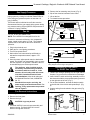
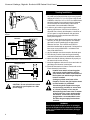
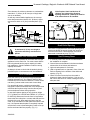
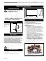
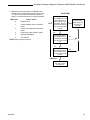
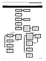
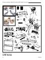
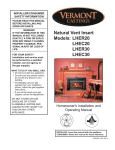
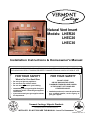
Natural Vent Insert
Models: LHER20
LHEC20
LHEC30
Installation Instructions & Homeowner's Manual
WARNING! IF THE INFORMATION IN THIS MANUAL IS NOT FOLLOWED EXACTLY, A FIRE OR
EXPLOSION MAY RESULT CAUSING PROPERTY DAMAGE,PERSONAL INJURY OR LOSS OF LIFE.
FOR YOUR SAFETY
What to Do if You Smell Gas:
•
•
•
•
•
Do not try to light any appliance.
Do not touch any electric switch.
Do not use any phone in your building.
Immediately call your gas supplier from your
neighbours phone. Follow the gas suppliers
instructions.
If you cannot reach your gas supplier call the
fire department.
FOR YOUR SAFETY
DO NOT STORE
OR USE GASOLINE OR OTHER
FLAMMABLE VAPOURS AND LIQUIDS
IN THE VICINITY OF THIS OR ANY
OTHER APPLIANCE.
• Installation and service must be performed
by a qualified installer, service agency or
your gas supplier.
DE S I GN
Vermont Castings, Majestic Products
410 Admiral Blvd. • Mississauga, Ontario, Canada L5T 2N6 • 905-670-7777
www.majesticproducts.com • www.vermontcastings.com
C E RT I F I E D
CE
RTIFI E D
INSTALLER: DO NOT DISCARD THIS MANUAL - Leave For Homeowner
10005360 6/03 Rev. 0
Vermont Castings, Majestic Products LHE Natural Vent Insert
Table of Contents
PLEASE READ THE INSTALLATION & OPERATING INSTRUCTIONS BEFORE USING THIS APPLIANCE.
Thank you and congratulations on your purchase of a Vermont Castings fireplace insert.
IMPORTANT - Read all instructions and warnings carefully before starting installation. Failure to follow these
instructions may result in a possible fire hazard and will void the manufacturers' warranty.
Installation Instruction
Important Curing/Burning Instructions ............................................................................................... 3
Locating Your Fireplace Insert .......................................................................................................... 3
Insert Applications ............................................................................................................................. 3
Fireplace & Trim Dimensions ............................................................................................................ 4
Mantels .............................................................................................................................................. 5
Framing & Finishing .......................................................................................................................... 5
Zero Clearance Applications ............................................................................................................. 5
Gas Specifications ............................................................................................................................ 6
Gas Inlet & Manifold Pressures ......................................................................................................... 6
High Elevations ................................................................................................................................. 6
Preparation ........................................................................................................................................ 6
Gas Line Installation .......................................................................................................................... 6
Gas Supply Pressures ...................................................................................................................... 7
Fan Kit ............................................................................................................................................... 7
Fan Removal Instructions ................................................................................................................. 7
Installation of Trim Switch for RN/RP Gas Valves ............................................................................. 7
Venting and Installation ..................................................................................................................... 8
Common Flue Installations ................................................................................................................ 9
Liner Installation ................................................................................................................................ 9
Draft Relief Opening .......................................................................................................................... 9
Test Chimney Draw ........................................................................................................................... 9
Vent Safety System ......................................................................................................................... 10
Vent Safety Switch Access ............................................................................................................. 10
Ceramic Refractory Installation ....................................................................................................... 10
Operating Instructions
General Glass Information ............................................................................................................. 11
Louvre Removal .............................................................................................................................. 11
Glass Cleaning ................................................................................................................................ 11
Glass Frame Removal ..................................................................................................................... 11
Log & Burner Lava Rock Installation ............................................................................................... 11
Large Lava Rock Placement ........................................................................................................... 12
Flame Adjustment ........................................................................................................................... 12
Flame Characteristics ...................................................................................................................... 12
First Firing ....................................................................................................................................... 13
Lighting & Operating Instructions .................................................................................................... 14
Troubleshooting Gas Control (820 Millivolt Gas Valve) .................................................................. 15
Troubleshooting Gas Control (Honeywell) ..................................................................................... 16
Instructions for RF Comfort Control Valve ...................................................................................... 17
Maintenance
Cleaning the Standing Pilot Control System ................................................................................... 21
Trim Cleaning .................................................................................................................................. 21
Replacement Parts .............................................................................................................................................. 22
Optional Accessories
Remote Controls ............................................................................................................................. 25
Zero Clearance Kit .......................................................................................................................... 25
Trim Options .................................................................................................................................... 25
Warranty .............................................................................................................................................................. 26
EnerGuide ............................................................................................................................................................ 28
2
10005360
Vermont Castings, Majestic Products LHE Natural Vent Insert
Installation & Operating Instructions
This gas appliance should be installed by a qualified installer
in accordance with local building codes and with current CSAB149.1 Installation codes for Gas Burning Appliances and
Equipment.
FOR U.S. Installations follow local codes and/or the current
National Fuel Gas Code ANSI Z223.1.
FOR SAFE INSTALLATION AND OPERATION OF
YOUR GAS FIREPLACE PLEASE NOTE THE
FOLLOWING:
1. This appliance gives off high temperatures and should be
located out of high traffic areas and away from furniture
and draperies.
2. Children and adults should be alerted to the hazards of the
high surface temperatures of this appliance and should
stay away to avoid burns or ignition of clothing.
3. Children should be carefully supervised when they are in
the same room as your appliance.
4. Under no circumstances should this appliance be modified.
Parts removed for servicing should be replaced prior to
operating this appliance again.
5. Installation and any repairs to this appliance should be
carried out by a qualified service person. A professional
service person should be contacted to inspect this appliance annually. Make it a practice to have all of your gas
appliances checked annually. More frequent cleaning may
be required due to excess lint and dust from carpeting,
bedding material, etc.
6. Control compartments, burners and air passages in this
appliance should be kept clean and free of dust and lint.
Make sure that the gas valve and pilot light are turned off
before you attempt to clean this unit.
7. The venting system (chimney) of this appliance should be
checked at least once a year and if needed your venting
system should be cleaned.
8. Keep the area around your appliance clear of combustible
materials, gasoline and other flammable vapor and liquids.
This appliance should not be used as a drying rack for
clothing, nor should Christmas stockings or decorations be
hung in the area of it.
9. Under no circumstances should any solid fuels (wood, coal,
paper or cardboard etc.) be used in this appliance.
10.Whether the zero clearance kit is installed directly on
carpeting, vinyl tile or any combustible material other than
wood, this heater must be installed on a metal or wood
panel extending the full width and depth of the heater. The
insert can not be installed directly onto or into
combustibles.
This appliance may be installed in an aftermarket
permanently located, manufactured (mobile) home,
where not prohibited by local codes.
This appliance is only for use with the type of gas
indicated on the rating plate.
Proposition 65 Warning: Fuels used in gas,
woodburning or oil fired appliances, and the products
of combustion of such fuels, contain chemicals known
to the State of California to cause cancer, birth defects
and other reproductive harm.
California Health & Safety Code Sec. 25249.6
10005360
IMPORTANT:
PLEASE READ THE FOLLOWING CAREFULLY
It is normal for fireplaces fabricated of steel to give off
some expansion and/or contraction noises during the
start up or cool down cycle. Similar noises are found
with your furnace heat exchanger or car engine.
It is not unusual for your Vermont Castings, Majestic
Products gas fireplace to give off some odor the first
time it is burned. This is due to the curing of the paint
and any undetected oil from the manufacturing process.
Please ensure that your room is well ventilated open all windows.
It is recommended that you burn your Vermont
Castings, Majestic Products fireplace for at least ten
(10) hours the first time you use it. If optional fan kit has
been installed, place fan in the "OFF" position during
this time.
Locating Your Gas Fireplace Insert with
Zero Clearance Kit
X
A
E
B
C
X
X
D
F
FP1249
Fig. 1 Locating unit with zero clearance kit.
A) Flat on wall
C) Island
E) *Flat on wall corner
B)
D)
F)
Cross corner
*Room divider
Chase installation
NOTE: (Fig. 1)
* When you install your Vermont Castings, Majestic Products
fireplace in (D) Room divider or (E) Flat on wall corner positions,
a minimum of 6 (X) inches (153mm) clearance must be maintained from the perpendicular wall and the outer edge of the trim.
Insert Applications
Before installing the gas fireplace insert, consideration
must be given to the functioning needs of the fireplace.
The size of the fireplace cavity (min. 25¹⁄₄"W x 17¹⁄₄"H x
13¹⁄₂" D for the LHEC20 and LHER20, 28³⁄₄"W x 21"H x
15¹⁄₂"D for LHEC30 ), the design of the chimney for
effective venting should be determined. The availability of
the gas supply as well as electricity for the insert fan
must be confirmed.
Your Natural Vent Insert unit is designed to
be vented vertically with a minimum height
of 12 feet and a maximum vertical height of
35 feet.
3
Vermont Castings, Majestic Products LHE Natural Vent Insert
Fireplace & Trim Dimensions
B
I
D
G
L
A
A
H J
B
C
K
Zero Clearance Kit
P
Insulation
M
U
Q V
T
S
F
E
O
R
Minimum Fireplace
Insert Opening
1
2
3
4
5
=
=
=
=
=
N
Air Circulating Channel
LHESSB
LHESLB/LHEABSL/LHESLGA
LHECSLB/LHECSLMB/LHECSLSA
LHEACNSS
LHETCK
LHEC20
T
R
I
M
F
I
R
E
P
L
A
C
E
M
I
N
I
M
U
M
4
O
P
E
N
I
N
G
A-1
B-1
A-2
B-2
A-3
B-3
A-4
B-4
A-5
B-5
C
D
E
F
G
H
I
J
K
L
M
N
O
P
Q
R
S
T
U
V
20⁷⁄₈"
30³⁄₄"
24¹⁄₄"
37¹⁄₂"
24¹⁄₄"
38¹⁄₈"
20³⁄₄"
30⁷⁄₈"
28"
45"
25⁵⁄₈"
16¹⁄₂"
35"
26⁵⁄₈"
13"
17"
13³⁄₈"
19¹⁄₈"
15"
10¹⁄₂"
8¹⁄₂"
37¹⁄₄"
19¹⁄₈"
27¹⁄₄"
17¹⁄₄"
25¹⁄₄"
13¹⁄₂"
17"
13³⁄₄"
18"
(530mm)
(781mm)
(616mm)
(952mm)
(616mm)
(968mm)
(527mm)
(784mm)
(711mm)
(1143mm)
(651mm)
(419mm)
(889mm)
(676mm)
(331mm)
(432mm)
(340mm)
(486mm)
(381mm)
(266mm)
(216mm)
(946mm)
(486mm)
(692mm)
(438mm)
(641mm)
(343mm)
(432mm)
(349mm)
(457mm)
Gas Inlet Knockout
Q - Fireplace opening height
R - Fireplace opening width
S - Depth of insert
T - Firebox width at insert depth(S)
LHER20
20⁷⁄₈"
30³⁄₄"
24¹⁄₄"
37¹⁄₂"
24¹⁄₄"
38¹⁄₈"
20³⁄₄"
30⁷⁄₈"
28"
45"
25⁵⁄₈"
16"
35"
26⁵⁄₈"
14"
17¹⁄₄"
13¹⁄₈"
19³⁄₈"
15"
11¹⁄₂"
8¹⁄₂"
37¹⁄₄"
19¹⁄₈"
27¹⁄₄"
17¹⁄₄"
25¹⁄₄"
14"
17"
14"
18"
(530mm)
(781mm)
(616mm)
(952mm)
(616mm)
(968mm)
(527mm)
(784mm)
(711mm)
(1143mm)
(651mm)
(406mm)
(889mm)
(676mm)
(355mm)
(438mm)
(333mm)
(492mm)
(381mm)
(292mm)
(216mm)
(946mm)
(486mm)
(692mm)
(438mm)
(641mm)
(355mm)
(432mm)
(355mm)
(457mm)
U - Firebox depth at insert back height (V)
V - Insert back height
NOTE: LHESLGA is only available for
Model LHEC30
LHEC30
26³⁄₄"
38¹⁄₄"
28³⁄₁₆"
41"
28¹⁄₄"
41¹¹⁄₁₆"
24³⁄₄"
34⁷⁄₁₆"
32¹⁄₄"
49"
29³⁄₁₆"
16⁷⁄₈"
35"
26⁵⁄₈"
15¹⁄₂"
20³⁄₄"
16"
23¹⁄₄"
17"
12³⁄₄"
8¹⁄₂"
37¹⁄₄"
19¹⁄₈"
27¹⁄₄"
21"
28³⁄₄"
16"
17³⁄₄"
16"
21⁵⁄₁₆"
(680mm)
(972mm)
(716mm)
(1042mm)
(717mm)
(1059mm)
(629mm
(875mm)
(819mm)
(1245mm)
(741mm)
(428mm)
(889mm)
(676mm)
(394mm)
(527mm)
(406mm)
(590mm)
(432mm)
(324mm)
(216mm)
(946mm)
(486mm)
(692mm)
(533mm)
(730mm)
(406mm)
(451mm)
(406mm)
(541mm)
10005360
Vermont Castings, Majestic Products LHE Natural Vent Insert
Mantels
When the unit is installed into a woodburning fireplace,
the minimum distance the mantel can be placed above
the fireplace is governed by local building codes
applicable to woodburning fireplaces. Consult local
authorities having jurisdiction for these clearances.
For applications requiring the use of a Zero Clearance
Kit, the minimum height a mantel can be installed
above the fireplace is 24" (610mm) from the top of the
upper louvres. The maximum mantel depth is 8"
(200mm). (Fig. 2)
37¹⁄₄" (946mm)
35"
(889mm)
The underside of the mantel will become
warm. Use only finishes which are heat
resistant and do not discolor.
Air Inlet Channel
27¹⁄₄" (692mm)
24" Min.
(610mm)
Drywall
19¹⁄₈"
(486mm)
Finish Wall
Decorative Trim Kit
FP1351
Fig. 3 LHE insert framing dimensions.
NOTE: Insulating around the fireplace will result in
overheating and possible malfunctioning of the circulating fan.
FP1325
Zero Clearance Applications
Fig. 2 Minimum mantel height above fireplace.
Framing & Finishing
For Zero Clearance Kit applications, it is important to
determine the finished facing material before beginning
to frame. This will allow for the thickness of the finishing
material between the frame and the fireplace trim.
Similarly, consideration must be given to the 1" inch
depth of the air inlet channel sitting on the fireplace
base. Finishing material for the hearth should be flush
with the top of the air inlet channel.
If the fireplace is installed at floor level a noncombustible hearth must extend a minimum 12" (305mm) in
front of the fireplace.
If the fireplace is recessed into the wall and at least 12"
(305mm) above floor level, no hearth is required.
An alternate air supply is recommended
with this component.
For installation other than in existing woodburning
fireplaces such as new construction or renovation
projects, a Zero Clearance Kit must be used. The kit
enables these inserts to be installed in combustible
environments. Whenever using a Zero Clearance Kit,
consideration must be given to the dimensions of the
Zero Clearance Kit and the requirements of the Air Kit.
NOTE: If a Zero Clearance Kit is required for models LHEC20/LHER20/LHEC30 Natural Vent Inserts,
only the Vermont Castings, Majestic Products zero
clearance kit HEZC is approved to be used. When
using the HEZC with insert models LHEC20 or
LHER20, the Trim Closure Kit, LHE20TCK, must
also be installed.
The use of wallpaper adjacent to this
fireplace is not recommended as high
temperatures given off by this fireplace
may adversely effect the binders in the
adhesive used to apply the wallpaper.
10005360
5
Vermont Castings, Majestic Products LHE Natural Vent Insert
Gas Specifications
Preparation
Model
Fuel
Gas Control
Max.
Input
Btu/h
Min.
Input
Btu/h
LHEC20RN
Natural Gas
Millivolt Hi/Lo
20,000
LHEC20RP
Propane Gas
Millivolt Hi/Lo
20,000
14,000
15,000
LHEC20RFN
Natural Gas Comfort Control 20,000
14,000
LHEC20RFP
Propane Gas Comfort Control 20,000
15,000
LHER20RN
Natural Gas
Millivolt Hi/Lo
20,000
14,000
LHER20RP
Propane Gas
Millivolt Hi/Lo
20,000
15,000
LHEC30RN
Natural Gas
Millivolt Hi/Lo
30,000
21,000
LHEC30RP
Propane Gas
Millivolt Hi/Lo
30,000
22,500
LHEC30RFN
Natural Gas Comfort Control 30,000
21,000
LHEC30RFP
Propane Gas Comfort Control 30,000
22,500
Gas Inlet & Manifold Pressures
Minimum Inlet Pressure
Maximum Inlet Pressure
Manifold Pressure
Natural
5.5" W.C.
14.0" W.C.
3.5" W.C.
LP
11.0" W.C.
14.0" W.C.
10.0" W.C.
Do not use this appliance if any part of it
has been under water. Immediately call a
qualified service technician to inspect the
unit and replace any part of the control
which has been under water.
These gas inserts are approved for installation in
solid fuel burning masonry or zero clearance
fireplaces.
LHEC20 / LHER20 / LHEC30
Certified To
ANSI Z 21.88-2002 / CSA 2.33-2002
Vented Gas Fireplace Heaters
High Elevations
Before beginning, remove glass door and logs from
unit. Also check to make sure there is no hidden
damage to the unit. Take a minute and plan out the
gas,venting and electrical route. It is best to start with
the gas line first followed by the chimney liner. (Refer to
Page 9)
Gas Line Installation
When purging the gas line, the front
glass must be removed.
If gas piping from the source to the heater location has
not been accomplished, install the required pipe.
Consult local plumbing code to assure proper pipe size.
The gas pipeline can be brought in through the rear or
the base of the heater.
NOTE: The gas line connection can be made of either
properly tinned 3/8" copper tubing, 1/2" rigid pipe or an
approved flex connector then reduced to 3/8" to the
heater. Some municipalities have additional local
codes, it is always best to consult your local authority
and the CSA- B149.1 installation code.
U.S. Installations consult the current National Fuel
Gas Code, ANSI Z223.1
Always check for gas leaks with a mild
soap and water solution. Do not use an
open flame for leak testing.
The gas control is equipped with a captured screw type
pressure test point, therefore it is not necessary to
provide a 1/8" test point up stream of the control.
When using copper or flex connector, use only
approved fittings. Always provide a union when using
black iron pipe so the gas line can be easily
disconnected for burner or fan servicing. See gas
specifications for pressure details and ratings. NOTE:
If flex connector is used, it must be kept inside of the
heater.
1/2" Gas Supply
Input ratings are shown in BTU per hour and are
certified without deration for elevations up to
4,500 feet (1,370m) above sea level.
1/2" x 3/8" Shut Off Valve
3/8" Nipple
For elevations above 4,500 feet (1,370m) in USA,
installations must be in accordance with the
current ANSI Z223.1 and/or local codes having
jurisdiction.
In Canada, please consult provincial and/or local
authorities having jurisdiction for installations at
elevations above 4,500 feet (1,370m).
6
3/8" Union
3/8"
Nipple
FP297
Fig. 4 Typical gas supply installation.
10005360
Vermont Castings, Majestic Products LHE Natural Vent Insert
Gas Supply Pressures
This heater must be isolated from the gas supply
piping system by closing its individual manual shut-off
valve during any pressure equal to or less than 1/2
psig (3.45kPa).
5.
6.
7.
8.
Remove the fan mounting nuts (2 nuts). (Fig. 5)
Slip off the electrical connector at the motor.
Lift out the fan.
To reinstall reverse procedure.
The heater and its individual shut-off valve must be
disconnected from the gas supply piping system during
any pressure testing of that system at test pressures in
excess of 1/2 psig (3.45kPa).
Screw
Stud
Thermal Sensor is
Attached to Burner
Base
Fan Kit
Fan is Installed at
the Back of the
Air Intake Box
Screw Stud
115 volt, 60 Hz. 56w (Model FK24)
NOTE: The LHER20 is not designed for a fan kit.
The fan kit includes the following: fan, temperature
sensor, speed control and a 6 ft. cord. The following
explains how to start and set the fan for automatic
operation.
1.
2.
3.
4.
Plug in the electrical cord.
Start gas fire - see lighting procedures.
Turn on fan speed control.
Wait until the unit has warmed up sufficiently to
activate the temperature sensor, approx. 5-10
minutes.
5. Once fan starts, adjust speed control to desired fan
speed. The fan will now automatically come on every
time the fireplace is in operation. Should the fan not
be needed simply turn off the speed control.
The appliance, when installed must be
electrically connected and grounded in
accordance with local codes or, in the
absence of local codes, with the current
CSA C22.1 Canadian Electrical Code.
U.S. Installations, follow local codes and
the National Electrical Code, ANSI/NFPA
No. 70.
Should this fan require servicing, the
power supply must be disconnected. For
rewiring of any replacement components
refer to Figure 6.
Fan Removal Instructions
1. Turn off gas and electricity.
2. Remove the front glass.
3. Remove the logs.
Fan Speed Control/Junction Box
FP1252
Fig. 5 Fan location.
Fan
Temperature Sensor
Speed
Control
Black
White
Ground
FP394
Fig. 6 Wiring diagram RN/RP. NOTE: For comfort valve
wiring diagram refer to Page 18, Figure 27.
Installation of Trim Switch
for RN/RP Gas Valves
1. Thread wire through openings on the right side of
fireplace. Do not cut wire or insulation on metal edges.
2. Insert ON/OFF switch with wiring assembly into the
bracket switch with the pre-punched opening mounted
on the right side of the trim. (Fig. 7)
3. For left side installation, relocate the bracket switch
to the left side of the trim kit and repeat Step 2. (Fig.
8)
4. Connect wiring from the switch to the gas valve (Fig.
9a & b).
Right Side Installation
Left Side Installation
On/Off
Switch
Assembly
On/Off
Switch
Assembly
CAUTION: Logs may be hot!
4. For Model LHEC20: remove burner assembly and
bracket rear log. For Model LHEC30: remove
bracket rear log and cover fan.
Wiring from
Millivolt Gas
Valve
FP1330
10005360
Fig. 7 Insert ON/OFF switch with wiring assembly into
bracket switch.
7
Vermont Castings, Majestic Products LHE Natural Vent Insert
Venting Installation
FP1331
Fig. 8 For left side installation, reverse switch position in
bracket.
SIT Valve
THTP
Thermopile
TP
TH
OT
PIL
FP382a
Fig. 9a On/Off switch or millivolt thermostat.
TPTH
TP
TH
Honeywell Valve
FP1218
Fig. 9b On/Off switch wiring.
CAUTION: Do not wire millivolt remote
wall switch for gas fireplace to a 120v
power supply.
1. The fireplace may be installed in and vented through
any solid fuel fireplace that has a minimum fireplace
opening 25¹⁄₄"W x 17¹⁄₂" H x 13¹⁄₂"D for LHEC20 and
LHER20 or 28³⁄₄"W x 21"H x 15¹⁄₂"D for LHEC30 and
has been installed in accordance with the National,
Provincial/State and local building codes and is
constructed of noncombustible materials.
2. In order to gain minimum gas insert fireplace
opening requirement, if the fire brick refractory is
removed from a factory built fireplace, a minimum of
1/4" air space is required between the gas insert
fireplace's outer casing and the inner wall of the
factory built fireplace.
3. In order to obtain the best performance, safety and
efficiency for the gas insert fireplace, the LHEC30
gas insert must be installed with an approved 4"
diameter flue liner. The LHER20 and LHEC20
should be installed with an approved 3" diameter flue
liner as per current CSA-B149.1 or National Fuel
Gas Code ANSI Z223.1.
4. Any flue damper must be removed or blocked open.
5. The chimney must be clean and in good working
order and constructed of noncombustible materials.
6. Make sure that all chimney cleanouts fit properly so
air cannot leak into the chimney.
7. Install the appliance without trim frame and make all
gas fittings and electrical connections.
8. Install the decorative trim frame. Please refer to the
Frame Assembly instructions.
Installer must attach red warning plate
with screws supplied with the gas fireplace insert to the inside of the firebox of
the fireplace into which the gas fireplace
insert is installed.
Cutting any sheet metal parts of the
fireplace, in which the gas fireplace insert
is to be installed, is prohibited.
If the factory-built fireplace has no gas
access hole(s) provided, an access hole
of 1.5 inch (37.5mm) or less may be
drilled through the lower sides or bottom
of the firebox in a proper workmanshiplike manner. This access hole must be
plugged with a noncombustible insulation after the gas supply line has been
installed.
WARNING
Some factory-built fireplaces have air passages
on face of fireplace for zero clearance capabilities.
Under no circumstances should these passages
be blocked.
8
10005360
Vermont Castings, Majestic Products LHE Natural Vent Insert
If the fireplace lintel is wider than 8"
(205mm), the height of the fireplace
opening must be 25" (635mm) to allow for
a 90° offset elbow to be installed.
Zero clearance kit minimum clearance to combustibles
materials is 1" (25mm) for B Vent (use of single wall
vent is not allowed.)
As with any natural drafted appliances, the vent cap
must always extend a minimum of 2' (610mm) above
any structure within a 10' (3m) horizontal plane. (Fig.
10)
Draft
Hood
0 To 10’
2’ Min.
3’
Min.
0 To 10’
(3m)
2’
(610mm)
Min.
Chimney Liner
Damper
Damper
Chimney
Liner
Clamp
Screw
Clamp
3’
(914mm)
Min.
Reference
Point
AC246a
ST1354
Fig. 1 Remove flue collar plate and attach to flue collar.
Draft Relief Opening
Fig. 10 Example of the 2', 3', 10' rule.
A minimum 12' (3.7m) vent height is
required to effectively vent these fireplaces.
Common Flue Installations
In some areas it is possible to vent more than one gas
appliance into the same flue. You must ensure that the
flue being shared has the proper capacity to handle
both appliances. Check installation codes for venting
capacity information.
As always it is best to check with the authority having
jurisdiction prior to commencement of the installation.
Liner Installation
Insert liner from top of chimney through the damper
opening and attach to 3" flue collar for LHEC20 and
LHER20 and 4" flue collar for LHEC30. For best results
use three (3) sheet metal screws and a hose clamp.
For natural draft inserts, packing noncombustible
fiberglass insulation around the liner in the damper area
will isolate the fireplace cavity from the chimney and
prevent drafts and noises during operation.
This insert is equipped with a draft-relief opening which
receives its dilution air supply through the opening at
the back of the insert. These openings must not be
obstructed or entered any way. (Fig. 12)
Test Chimney Draw
1. A "Chimney Draw" test must be conducted before
the installation is complete.
2. Close all doors and windows in the home and start
exhaust fans in he kitchen and bathroom.
3. Light unit and operate for 5 minutes.
4. Hold an ignited match or cigarette in front of the unit.
Refer to drawing for the location of the draft hood
opening. (Fig. 12)
5. Check to make sure smoke from the match or
cigarette is drawn into the fireplace. If it is not, turn
the unit off and check for causes creating the lack of
adequate draft.
Test for draft at these two
openings.
In case the fireplace opening is only minimum height
(17¹⁄₄" (438mm) for LHEC20 and LHER20; 21" (533mm)
for LHEC30) and access from the front is not possible,
remove the flue collar plate - unscrew and slide out from
the back of the unit. Now attach the liner to the flue
collar, lift up and slide flue collar plate back onto the unit
top. It is important that the plate is completely inserted
and the front screw is fastened again in order to line up
the flue outlet and the liner properly. (Fig. 11)
FP1355
Fig. 12 Hold an ignited match in front of fireplace.
10005360
9
Vermont Castings, Majestic Products LHE Natural Vent Insert
Blocked Flue Shut Off System
These inserts are equipped with a blocked flue shut off
switch. This switch is factory installed, wired and tested.
Check and make sure the switch and wires are in the
proper position. The shut off switch is heat activated
and wired in series with the pilot system. (Fig. 13)
Operation of this fireplace when not
connected to a properly installed and
maintained venting system or tampering
with the blocked flue shut-off system can
result in carbon monoxide (CO) poisoning and possible death.
screw that secures the switch assembly. Holding the
bracket switch carefully pull out the entire switch
assembly.
NOTE: The shut off switch cover was attached with the
gasket cover. Before installing the gasket cover back in
place, inspect and make sure the gasket is not damaged. If the gasket is damaged, install a new gasket.
Screw must be removed prior
to pulling the switch assembly
Cover
Safety
Switch
Gasket Cover
Safety Switch
Bracket Shut
Off Switch
Screws
Screws
Firebox Baffle
Bracket
FP1356
Blocked Flue Shut Off
Switch
Fig. 13 Blocked flue shut off switch location.
Blocked Flue Shut Off Switch Access
The shut off switch system of these inserts is designed
to be accessed from either inside the combustion
firebox chamber or outside at the back of the inserts
fireplace.
Access to the shut off switch from outside of the
insert
1. Turn off the unit and let it cool down if it has been
operating.
2. Shut off the gas and the electrical source to the
fireplace.
3. Disconnect the gas line and the draft hood of the
fireplace.
4. Slide the fireplace out.
Access to the shut off switch directly from inside
the combustion firebox chamber.
1. Turn off the unit and let it cool down if it has been
operating.
2. Remove the log set and remove the ceramic refractory if installed.
3. Remove the firebox baffle. (Fig. 14)
4. Remove the shut off switch cover fastened with four
(4) screws located at the right upper corner of the
firebox.
5. This time you can access the shut off switch assembly through the rectangular opening. Remove the
Screws
FP1352
Fig. 14 Access to the blocked flue shut off swtich from inside
combustion chamber.
Ceramic Refractory Installation
1. Remove front glass.
2. Remove logs from unit.
3. Remove refractory from package.
Refractory are fragile and must be handled with care. Where at all possible, two
hands should be used when handling.
4. Take center refractory and tilt so bottom edge seats
onto the rear log bracket at the back wall of the
fireplace. (Fig. 15)
5. Press center refractory to back side of fireplace and
hold in place.
6. Take left or right refractory and align it so leading
edge faces outward. (Place refractory in fireplace
side and slide it back to support the center refractory.)
7. Repeat step 6 for remaining side refractory.
8. Fasten bracket supports against refractory top to
hold side in place.
When side refractory is installed correctly, the center refractory will be supported by the side refractory.
Leading Edge
Leading Edge
Bottom Edge
Left Side
Center
Right Side
FP1329
10
Fig. 15 Ceramic refractory.
10005360
Vermont Castings, Majestic Products LHE Natural Vent Insert
Operating Instructions
General Glass Information
Only ceramic glass approved by Vermont
Castings, Majestic Products may be used
for replacement on this unit.
1. The use of substitute glass will void all product
warranties.
2. Care must be taken to avoid breakage of the glass.
3. Under no circumstances should this appliance be
operated without glass properly installed, or with any
cracked or broken glass. Replacement of any glass
assembly as supplied by the manufacturer should be
done by a licensed qualified service person.
Louvre Removal
To remove
louvre, lift louvre
up and then pull
out.
(Fig. 16)
2.
Louvre
1.
Glass Panel
FP444
Fig. 16 Louvre removal.
Glass Cleaning
It will be necessary to clean the glass periodically.
During start-up condensation, which is normal, forms
on the inside of the glass and causes lint, dust and
other airborne particles cling to the glass surface. Also
initial paint curing may deposit a slight film on the
glass. It is therefore recommended that the glass be
cleaned two or three times with a non-ammonia
household cleaner and warm water (we recommend
gas fireplace glass cleaner). After that the glass should
be cleaned two or three times during each heating
season depending on the circumstances present.
Machine Screw
FP1353
Fig. 17 Remove glass frame.
Log Installation and Burner Lava Rock
1 . Remove glass frame. (See "Glass Removal" section)
2. Remove logs from packaging.
3. Place logs according to the model instructions
below:
LHEC20, LHER20 (Figs. 18)
a. Place rear left log (JR7). Use the log's bottom
holes to locate it onto one pin stud of the rear log
bracket on the left and the other end of the log
will sit on top of the lid of the left log support.
b. Place rear right log (JR8). Use the log's bottom
holes to locate it onto the two (2) pin studs of the
rear log bracket on the right.
c. Place the front left log (JR9). Position the log
notch against the second grate from the left, and
the other edge of the log on top of the rear left log
notch. Ensure the log is secure in place.
d. Place the front right log (JR10). Position the log
notch against the third grate from the right, and
the other edge of the log on top of the rear right
log notch. Ensure the log is secure in place.
e. Place the burner lava rock on the front area of the
burner housing. (Fig. 18)
JR7
JR8
Clean glass after first two weeks of
operation.
JR10
JR9
Glass Frame Removal
1. Remove two (2) screws at the bottom of the frame.
(Fig. 17)
2. Lift up and unhook glass frame at the top.
Front Grate
Burner Lava Rock
LG285
Fig. 18 LHEC20 and LHER20 log and lava rock placement.
10005360
11
Vermont Castings, Majestic Products LHE Natural Vent Insert
KR24
KR25
Turn
counterclockwise
to decrease
flame height
LO
Honeywell Valve
HI
Turn clockwise
to increase
flame height
Fig. 20 Flame adjustment knob for Honeywell Valve.
SIT Valve
Turn
counterclockwise
to increase
flame height
HI
LHEC30 (Fig. 19)
a. Place the rear center log (KR24). Use the log's
bottom holes to locate it onto the two (2) pin studs
of the rear log bracket on the center.
b. Place rear left log (KR22). Use the log's bottom
holes to locate it onto the two (2) pin studs of the
rear log bracket on the left.
c. Place rear right log (KR23). Use the log's bottom
holes to locate it onto the two (2) pin studs of the
rear log bracket on the right.
d. Place the front left log (KR25). Position the log
notch against the second grate from the left, and
the other edge of the log on top of the rear left log
notch. Ensure the log is secure in place.
e. Place the front right log (KR26). Position the log
notch against the third grate from the right, and
the other edge of the log on top of the rear right
log notch. Ensure the log is secure in place.
f. Place the burner lava rock on the front area of the
burner housing. (Fig. 19)
LO
Turn clockwise
to decrease
flame height
Fig. 21 Flame adjustment knob for SIT Valve.
Flame Characteristics
It is important to periodically perform a visual check of
the pilot and the burner flames. Compare them to the
Figure 22 and Figure 23 or 24. If any of the flames
appear abnormal call a service person.
KR23
KR22
PSE Pilot
3/8" - 1/2"
KR26
Front Grate
Burner Lava
Rock
LG286
Fig. 19 LHEC30 log and lava rock placement.
SIT Pilot
F584-703
Fig. 22 Correct pilot flame appearance.
Large Lava Rock Placement
The large lava rock provided with this fireplace should
be placed on the firebox base on either side of the
burner assembly.
Under no circumstances should these
lava rocks be placed on top of the burner
assembly.
Flame Adjustment (RN/RP Models)
For fireplaces equipped with HI/LO valves, flame
adjustment is accomplished by rotating the HI/LO
adjustment knob located near the center of the gas
control. (Figs. 20 or 21)
12
LG287
Fig. 23 Correct burner flame appearance for LHEC20 and
LHER20.
10005360
Vermont Castings, Majestic Products LHE Natural Vent Insert
First Firing
Upon completing the gas line connection, a small
amount of air will be in the lines. When first lighting unit
with pilot light, it will take a few minutes to purge themselves of this air. Once the purging is complete, the
pilot and burner will light and operate as indicated in the
instruction manual. Subsequent lightings of the heater
will not require such purging.
LG288
Fig. 24 Correct burner flame appearance for LHEC30.
10005360
When lit for the first time, the appliance will emit a slight
odor for awhile. This is due to paint and lubricants used
in the manufacturing process. After each lighting, vapor
may condense and fog the glass; this moisture disappears within a few minutes of burning.
13
Vermont Castings, Majestic Products LHE Natural Vent Insert
Lighting And Operating Instructions
FOR YOUR SAFETY READ BEFORE LIGHTING
WARNING:If you do not follow these instructions exactly, a fire or explosion
may result causing property damage, personal injury or loss of life.
A. This heater has a pilot which must be lit manually. When lighting the pilot follow these instructions exactly.
B. BEFORE LIGHTING smell all around the heater
area for gas. Be sure to smell next to the floor
because some gas is heavier than air and will
settle on the floor.
WHAT TO DO IF YOU SMELL GAS
• Do not try to light any fireplace
• Do not touch any electric switch
• Do not use any phone in your building
• Immediately call your gas supplier from a
neighbor's phone. Follow the gas supplier's
instructions.
• If you cannot reach your gas supplier, call
the Fire Department
C. Use only your hand to push in or turn the gas
control knob. Never use tools. If the knob will not
push in or turn by hand, do not try to repair it, call a
qualified service technician. Applying force or any
attempted repair may result in a fire or explosion.
D. Do not use this fireplace if any part has been under
water. Immediately call a qualified service technician to inspect the heater and to replace any part of
the control system and any gas control which has
been under water.
Lighting Instructions
1. STOP! Read the safety information above.
2. Turn off all electrical power to the fireplace.
3. For MN/MP/TN/TP appliances ONLY, go on to
Step 4. For RN/RP appliances turn the On/Off
switch to “OFF” position or set thermostat to
lowest level.
4. Open control access panel.
5. Push in gas control knob slightly and turn
to "OFF".
clockwise
3/8" - 1/2"
OFF
3 4 5
OFF
Euro SIT
SIT NOVA
ON
OFF
OT
L
PI
ON
1 2
P
OFF ilot
PILOT
10. Push the control knob all the way in and hold.
Immediately light the pilot by repeatedly depressing the piezo spark ignitor until a flame appears.
Continue to hold the control knob in for about one
(1) minute after the pilot is lit. Release knob and it
will pop back up. Pilot should remain lit. If it goes
out, repeat steps 5 through 8.
Honeywell
6. Wait five (5) minutes to clear out any gas. Then
smell for gas, including near the floor. If you
smell gas, STOP! Follow "B" in the safety
information above. If you do not smell gas, go
to the next step.
7. Remove glass door before lighting pilot. (See
Glass Frame Removal section).
8. Visibly locate pilot by the main burner.
9. Turn knob on gas control counterclockwise
to "PILOT".
•
If knob does not pop up when released, stop
and immediately call your service technician or
gas supplier.
•
If after several tries, the pilot will not stay lit,
turn the gas control knob to " " and call your
service technician or gas supplier.
11. Replace glass door.
12. Turn gas control knob to “ON” position.
13. For RN/RP appliances turn the On/Off switch to
“ON” position or set thermostat to desired setting.
14. Turn on all electrical power to the fireplace.
To Turn Off Gas To Heater
1. Turn the On/Off switch to "OFF" position or set
the thermostat to lowest setting.
2. Turn off all electric power to the fireplace if
service is to be performed.
14
3. Open control access panel.
4. Push in gas control knob slightly and turn
clockwise
to "OFF". Do not force.
5. Close control access panel.
10005360
Vermont Castings, Majestic Products LHE Natural Vent Insert
Troubleshooting the Gas Control System
SIT NOVA 820 Millivolt Valve
NOTE: Before trouble shooting the gas control system, be sure external gas shut off is in the “On” position.
WARNING: Before doing any gas control service work, remove glass front.
SYMPTOM
1. Spark ignitor will not light
2. Pilot will not stay lit after
carefully following lighting
instructions.
3. Pilot burning, no gas to
main burner
4. Frequent pilot outage
problem.
10005360
POSSIBLE CAUSES
CORRECTIVE ACTION
A. Defective or misaligned
electrode at pilot.
Using a match, light pilot. If pilot lights, turn off
pilot and push the red button again. If pilot will not
light - check gap at electrode and pilot-should be
1/8" to have a strong spark.
B. Defective ignitor (Push Button)
Push Piezo Ignitor Button. Check for spark at
electrode and pilot. If no spark to pilot, and elec
trode wire is properly connected, replace ignitor.
A. Defective pilot generator
(thermocouple), remote wall
switch.
Check pilot flame. Must impinge on thermo
couple/thermopile. Note: this pilot burner assem
bly utilizes both-a thermocouple and a thermopile.
The thermocouple operates the main valve
operation (On and Off). Clean and or adjust pilot for
maximum flame impingement on thermopile and
thermocouple.
B. Defective automatic valve
Turn valve knob to “Pilot”. Maintain flow to pilot;
milivolt meter should read greater than 10 mV. If
the reading is okay and the pilot does not stay on,
replace the gas valve. Note: An interrupter block
(not supplied) must be used to conduct this test.
A. Wall switch or wires defective
Check wall switch and wires for proper connec
tions. Jumper wire accross terminals at wall
switch, if burner comes on, replace defective wall
switch. If okay, jumper wires across wall switch
wires at valve, if burner comes on, wires are faulty
or connections are bad.
B. Thermopile may not be
generating sufficient
millivoltage.
1. Be sure wire connections from thermopile at
gas valve terminals are tight and thermopile is
fully inserted into pilot bracket.
2. One of the wall switch wires may be grounded.
Remove wall switch wires from valve terminals if
pilot now stays lit, trace wall switch wiring for
ground. May be grounded to fireplace or gas
supply.
3. Check thermopile with millivolt meter. Take
reading at thermopile terminals of gas valve.
Should read 250-300 millivolts (minimum 150)
while holding valve knob depressed in pilot
position and wall switch “Off”. Replace faulty
thermopile if reading is below specified minimum.
C. Plugged burner orifice.
Check burner orifices for debris and remove.
D. Defective automatic valve
operator.
Turn valve knob to “On”, place wall switch to “On”
millivolt meter should read greater than 100 mV. If
the reading is okay and the burner does not come
on, replace the gas valve.
A. Pilot flame may be too low
or blowing (high) causing the
pilot safety to drop out.
Clean and/or adjust pilot flame for maximum flame
impingement on thermopile and thermocouple.
B. Possible blockage of the vent
terminal.
Check the vent terminal for blockage (recycling the
flue gases)
15
Vermont Castings, Majestic Products LHE Natural Vent Insert
Troubleshooting the Gas Control System
Honeywell Millivolt Valve
START
CHECK
Gas Supply On
NO
Supply Line Hooked Up
Shutoff Valve Open
YES
Pilot Lights With
Piezo Ignitor
NO
YES
Pilot Stays Lit
NO
Lockout Has Engaged. Wait
60 Seconds And Try Again.
For Spark At Electrode While
Depressing Piezo 1/8" Gap To
Pilot Hood Needed.
All Wiring Connections
Replace Piezo Ignitor
For Air In The Lines
Thermopile Needs A Minimum
325mv. Adjust Pilot Flame Height.
All Wiring Connections.
Replace Thermopile
Thermocouple Needs A Minimum
of 14mv.
Defective Valve. Turn To Pilot,
Meter Should Read Greater Than
100 Mv. If Not, Replace.
YES
Pilot Lights Main
Burner
YES
NO
Valve Is Turned On
On/off Switch Is Not Turned On.
Watch For Grounded Wires!
Thermopile Needs A Minimum
325mv.
Plugged Burner Orifice.
System OK.
16
10005360
Vermont Castings, Majestic Products LHE Natural Vent Insert
Instructions for RF Comfort Control Valve
The Comfort Control Valve allows remote control of
temperature, fan and flame appearance.
NOTE: The antenna should hang in free air away from
grounded metal.
Operation
1. If the manual switch is in remote position, switch it to
LOCAL. (Fig. 25)
2. Turn the pilotstat knob counterclockwise from OFF
to the PILOT position, push the knob down, and hold
in position. The pilot valve opens and allows gas to
flow to the pilot burner.
3. Push plunger on the piezo until the pilot burner is lit.
When the pilot burner is lit, the LED on the control
will come on after approximately 40 seconds and will
be continuously red. When the light turns off which
will be approximately 10 seconds after it has been
continuously red, the receiver/valve is fully powered.
7. If the manual switch is in the LOCAL position, the
valve will be at the highest fixed pressure setting.
The transmitter will control the fan only.
Shut Off Procedure
If the manual switch is in the REMOTE position, the
transmitter can shut off the main burner and fan.
However, the control is still on and a command from the
transmitter can turn on the main burner or fan.
To shut off the system, turn the pilotstat knob clockwise
to the OFF position. This action closes the main gas
and safety valves. The transmitter cannot turn on the
main burner or fan.
Transmitter Operation
Off Mode
In the OFF mode, the fireplace flame and fan are off,
the display will show OFF and displays the room
temperature. If the receiver is in REMOTE mode, the
fireplace will shut off.
Piezo Ignitor
Mode
Auto
On
Off
OFF
•
O
• N
OT
PIL
Display
Room Temperature
Set Temperature
Flame Height Level
Fan Speed Level
Countdown Timer
Low Battery
Flame
LE
D
REMOTE
LOCAL
Up
Increases Flame
Height, Fan Speed
Timer, or Set Point
Countdown
Timer
LED
Local/Remote
Switch
Pilotstat Knob
Antenna
FP1037
Fig. 25 Comfort conrol valve.
4. Release the knob. The shaft will move upward. The
pilot burner should now stay burning. If the pilot
burner goes out, repeat step 2.
5. Turn the knob counterclockwise to the ON position. If
the manual switch is in the LOCAL position, the main
burner will turn on immediately.
6. ON the initial use of a transmitter, a recognition
operation is required between the receiver/valve and
transmitter. Change the switch from LOCAL to
REMOTE. Press the fan or flame button on the
transmitter within 30 seconds. The LED will blink
indicating the transmitter will now work with the
receiver/valve. If the switch continues in the REMOTE position, the transmitter will now control the
main valve, flame modulation level and fan control.
10005360
Down
Decrease
Flame, Fan
Speed Timer
or Set Point
Fan
FP1039
Fig. 26 Transmitter diagram.
On (Manual) Mode
In the ON mode, the room temperature, flame and fan
levels will be shown. MANUAL will appear next to both
the flame and fan icons.
When the control is in the ON mode, the flame and fan
levels, and delay timer are changed with the up and
down buttons. To change the flame level, press the
flame button followed by an arrow key. To change the
fan level, press the fan key followed by an arrow key.
Pushing the arrow key once will change the level by
one unit.
17
Vermont Castings, Majestic Products LHE Natural Vent Insert
Delay Timer Mode
Pilot
Assembly
The shut off delay timer has a maximum of 2 hours and
a minimum of zero minutes. To change the timer level,
press the time key followed by an arrow key. Pushing
the key once will change the timer by 10 minutes.
Fan
Auto Mode
In the AUTO mode, the room temperature, set temperature, flame and fan levels will be shown. AUTO will
appear next to both the flame and fan icons.
When the control is in the AUTO mode, the main burner
will turn on/off or modulate based on the heat needed to
maintain the set temperature. The flame level will
change automatically to optimize the heat output
needed to maintain the set temperature. To change the
set temperature, press the up or down key. Pushing a
key once will change the temperature by one degree.
Fan Override During Auto Mode
If a lower or higher fan speed is desired when operating
in the AUTO mode, the fan speed can be overridden by
pushing the fan button followed by the up or down key.
Pushing a key once will change the fan level by one
unit. In this mode “AUTO” is displayed next to the flame
icon and “MANUAL” is displayed next to the fan icon.
Change Between F/C Temperature Units
Push the up and down arrow keys simultaneously for at
least 3 seconds to toggle between Fahrenheit and
Celsius units.
Disable Thermostat Function
To disable the thermostat function in the AUTO mode,
push the time and down keys simultaneously for at
least 3 seconds.
To Change Batteries
1. Remove cover on the backside of the transmitter.
Install 3 AAA batteries as shown and reattach cover.
2. Once steps 1-3 in OPERATION are completed,
receiver/valve and transmitter are now ready. Press
any button on transmitter for recognition process to
occur between the receiver/valve and transmitter.
3. Use functions as described in TRANSMITTER
section.
FAN
In the AUTO mode, the fan speed will increase with
increasing flame height or decrease with decreasing
flame height. “AUTO” is displayed next to the flame and
fan icons.
Red
White
Red
White
White Dots
Antenna
FP1038
Valve
(Bottom View)
Fig. 27 Comfort Valve wiring diagram.
Troubleshooting
1. Locate LED light on valve.
2. LED will blink after every valid command received by
the transmitter; this is not an error.
3. Failure codes may occur anytime after pilot burner is
lit.
4. Sequence is failure code followed by light not
blinking for 30 seconds.
5. In the event of multiple failure codes, next failure
code follows previous failure code by approximately
3 seconds.
If an Error Code 3 is observed while performing the
testing, complete the following:
1. Make sure the spade connectors are pushed all the
way on. If the Error Code 3 is still showing, then go
to the next step.
2. Switch the front two thermopile leads with the back
two. Be sure the white lead is connected to the
spade with the white dot next to it. If the Error Code
3 is still showing, replace the thermopiles.
If an Error Code 8 is observed while performing the
testing, complete the following:
1. Confirm the valve is not in REMOTE mode.
• If the valve is producing Error Code 8 and in
REMOTE mode, the valve is defective and should
be replaced.
• If the valve is in LOCAL mode and producing
Error Code 8, then go to the next step.
18
10005360
Vermont Castings, Majestic Products LHE Natural Vent Insert
2. Slide the Remote/Local switch to REMOTE and
teach the valve a transmitter (refer to Item 6, page
1). The Error Code will clear itself after approximately 1¹⁄₂ minutes and return to normal operation.
LED Count
Service Action
Auto Path
If the manual switch is
set to REMOTE, press
the mode button to
display AUTO on the
transmitter. Does the
transmitter display the
room and temperature
setting?
8
Replace valve
7
Confirm stepper motor connection
exists
5
Confirm fan connection exists and
works
4
Confirm gas type; jumper in place
Yes
3
Replace thermopiles
2
Turn fan ON
If the setting is above
room temperature on
the transmitter, does the
main valve and fan turn
on?
NOTE: Some keys are not active.
Move switch from
LOCAL to REMOTE. Press any
key within 30
seconds.
No
Yes
If the setting is below
room temperature on
the transmitter, does
the main valve and fan
turn off?
No
Turn pilotstat knob to
OFF to turn valve
completely off
10005360
19
Vermont Castings, Majestic Products LHE Natural Vent Insert
Comfort Valve system control sequence of operation with transmitter
Set manual switch
to local or remote
Five minute wait
period
Light pilot burner
No
Did the LED stop
blinking?
Review LED
failure analysis
Release pilotstat
knob
Yes
Turn pilotstat knob
from PILOT to ON
Cycle switch once
and leave in
remote. Press any
key on transmitter
for recognition
operation
Choose Local or
Remote path. Set
switch to manual or
remote
On Path
Local Path
If manual switch is
set to LOCAL, did
main burner light?
Move switch from
local to remote.
Press any key on
transmitter. Move
switch back to
local
Yes
Transmitter
controls fan
Yes
Turn pilotstat knob
to PILOT to turn
off main burner
No
If the manual switch
is set to REMOTE,
press the mode
button to display
"ON". Does transmitter control the main
burner and fan?
Move switch from
manual to remote.
Press any key on
transmitter.
Yes
Does transmitter
change levels of
flame height, fan
speed and set
temperature?
No
Yes
Turn pilotstat knob
to OFF to turn
valve completely
off
Set levels of flame
height and fan to
“0” to shut off main
burner and fan
Turn pilotstat knob
to OFF to turn
valve completely
off
20
10005360
Vermont Castings, Majestic Products LHE Natural Vent Insert
Maintenance
Burner and Burner Compartment
It is important to keep the burner and the burner
compartment clean. At least once per year the logs and
lava rock/ember material should be removed and the
burner compartment vacuumed and wiped out. Remove
and replace the logs as per the instructions in this
manual.
Always handle the logs with care as they
are fragile and may also be hot if the
fireplace has been in use.
Fan Assembly
The fan unit requires periodic cleaning. At least once
per month in the operating season, open the lower
louvre panels and wipe or vacuum the area around the
fan to remove any build up of dust or lint.
Visually inspect pilot. Brush or blow away any dust or
lint accumulation. If pilot orifice is plugged, disassembly
may be required to remove any foreign material from
the orifice or tubing.
To obtain proper operation, it is imperative that the pilot
and burner's flame characteristics are steady, not lifting
or floating.
Typically, the top 1/8" of the thermopile should be
engulfed in the pilot flame. (Page 12, Fig. 22)
Trim Cleaning
Clean the trim with a soft clean cloth, slightly dampened
with lemon oil and buff with a soft dry cloth. Do not use
brass polish or household cleaners as these products
will damage the trim. Lemon oil can be obtained at
supermarkets or hardware stores.
Cleaning the Standing Pilot
Control System
The burner and control system consists of:
• main burner
• pilot burner
• gas orifice
• thermopile
• combination millivolt gas valve
Most of these components may require only an occasional checkup and cleaning and some may require
adjustment. If repair is necessary, it should be performed by a qualified technician.
In order to properly clean the burner and pilot assembly,
turn off the gas to the unit, remove the window frame
panel and logs exposing the burner and pilot assembly.
Clean all foreign materials from the top of the burner.
Check to make sure that burner parts are clean.
10005360
21
Vermont Castings, Majestic Products LHE Natural Vent Insert
LHER20/LHEC20
18
10a/b
1b
4
2
1a
5
3
1e
16
14
1d
6a/b
LHEC30
19
18
17
1c
8a/b
11a/b
1b
1a
7a/b
13a/b
9 a/b
1e
20
15
1d
21
22a/b
12a/b
28/29
OFF
PI
O H
PILOT
ADJ
ON
L
I
LO
T
27
30
24a/b
23 a/b
26
T
OFF
¥
41
LE
D
REMOTE
LOCAL
ON
¥
O
PIL
32
31
33
47
25
35
42
48
46
34
45
44
49
43
51
36
40
50
37
38
52
5360
Vermont Castings, Majestic Products reserves the right to make changes in design, materials, specifications, prices and discontinue colors and
products at any time, without notice.
LHE Series
22
10005360
Vermont Castings, Majestic Products LHE Natural Vent Insert
LHE Series (continued)
Ref.
Description
LHER20
1.
1a.
1b.
1c.
1d.
1e.
2.
3.
4.
5.
6a.
6b.
7a.
7b.
8a.
8b.
9a.
9b.
10a.
10b.
11a.
11b.
12a.
12b.
13a.
13b.
14.
15.
16.
17.
18.
19.
20.
21.
22a.
22b.
23a.
23b.
24a.
24b.
25.
26.
27.
28.
29.
30.
31.
32.
33.
Log Set Complete
Log Rear Left
Log Rear Right
Log Rear Center
Log Front Left
Log Front Right
Lava Rock Burner Package
Lava Rock Package
Burner Housing Assembly with Tiles
Ceramic Tile (Single)
Orifice Front Burner (Nat.)
Orifice Front Burner (Prop)
Orifice Rear Burner (Nat.)
Orifice Rear Burner (Prop.)
Orifice Pilot SIT Top Convertible
Orifice Pilot SIT Top Convertible
Orifice Pilot PSE (Nat.)
Orifice Pilot PSE (Prop.)
Pilot Assembly SIT Top Convertible (Nat.)
Pilot Assembly SIT Top Convertible (Prop.)
Pilot Assembly PSE ( Nat.)
Pilot Assembly PSE (Prop.)
Pilot Assembly RFN (Nat.)
Pilot Assembly RFP (Prop.)
Pilot Orifice RFN (Nat.)
Pilot Orifice RFP (Prop.)
Pilot Tubing w/Fittings
Manifold Tubing w/Fittings
Thermocouple SIT
Thermocouple PSE
Thermopile
Electrode Ignitor w/Cable SIT
Ignitor Piezo SIT
Ignitor Piezo Honeywell
Valve SIT 820 RN
Valve SIT 820 RP
Valve Honeywell RN
Valve Honeywell RP
Valve Honeywell RFN
Valve Honeywell RFP
Antennae (for RFN or RFP Units)
Transmitter (for RFN or RFP Units)
Thermopile (for RFN or RFP Units)
Cord Set (for RFN or RFP Units)
Cord Set (for RN or RP Units)
Fan with Bracket
Fan Temperature Sensor (for RN orRP Units)
Speed Control Switch (for RN or RP Units)
Speed Control Knob (for RN or RP Units)
10005332
10005332
10004866
JR7
JR7
KR22
JR8
JR8
KR23
KR24
JR9
JR9
KR25
JR10
JR10
KR26
57897
57897
57897
10001454
10005294
10005294
10004972
57803
57803
57803
See Rating Plate for Orifice Size
See Rating Plate for Orifice Size
See Rating Plate for Orifice Size
See Rating Plate for Orifice Size
10002268
10002268
10002268
10002269
10002269
10002269
10001822
10001822
10001822
10001823
10001823
10001823
10002389
10002389
10002389
10002390
10002390
10002390
10001741
10001741
10001741
10001742
10001742
10001742
20002266
20002266
20002268
20002268
20000908
20000908
20000907
20000907
10001296
10001296
10001296
57318
57318
57318
53373
53373
53373
10001825
10001825
10001825
51827
51827
51827
10001297
10001297
10001297
52464
52464
52464
20000062
20000062
20000062
52677
52677
52677
52678
52678
52678
10001782
10001782
10001782
10001759
10001759
10001759
20003719
20003719
20003720
20003720
20003561
20003561
20002047
20002047
20002400
20002400
20002541
20002541
51865
51865
51865
54103
54103
54103
51704
51704
51704
51738
51738
51738
51882
51882
51882
10005360
LHEC20
LHEC30
23
Vermont Castings, Majestic Products LHE Natural Vent Insert
LHE Series (continued)
Ref.
34.
35.
36.
37.
38.
39.
40.
41.
42.
43.
44.
45.
46.
47.
48.
49.
50.
51.
52.
24
Description
LHER20
LHEC20
LHEC30
Glass with Gasket
Gaskeet Glass
Frame Window
Remote Switch (for RN or RP Units)
Remote Wire Harness w/Terminals (for RN or RP Units)
Ceramic Fiber Brick FP (Optional)
Bracket Sensor
Flexible Connector (6")
Bracket Rear Log Assembly
Bracket Log Support Assembly
Gasket Cover Sensor Access
Bracket Support Grate
Hinge 2 Springs
Shield Heat Pilot
Sensor Safety Switch Assy
Grate Assembly Flat Black
Sensor Spill Switch
Bracket ON/OFF Switch
Wiring Safety Switch
10005526
57317
10005295
53606
10002582
JT1TR0
10004980
10005098
10005370
10005007
52356
10000248
10005074
10004967
51866
10005035
10005073
10005525
57317
10005067
53606
10002582
JT1TC0
10004980
10005098
10005369
10005007
52356
10000248
10005074
10004967
51866
10005035
10005073
10004989
57317
10004873
53606
10002582
KT1TC0
10004980
10005098
10005489
10004885
10005007
10003479
52356
10000248
10005074
10004967
51866
10005035
10005073
10005360
Vermont Castings, Majestic Products LHE Natural Vent Insert
Optional Accessories
Remote Controls
Trim Options
Optional remote control units are available to control
different functions of the appliance.
Model
MRC1
MRC2
MRC3
IMT
Function(s) Controlled
ON/OFF
ON/OFF and Temperature
ON/OFF and Temperature control
with a digital and a programmable
24 hour clock
Wall mounted thermostat control
NOTE: These remote controls are for RN/RP units
only.
Zero Clearance Kit
For installations other than in existing woodburning
fireplaces such as new construction or renovation
projects, a Zero Clearance Kit must be used. The
HEZC enables these inserts to be installed in combustible environments. It is recommended that an Air Kit
(AKZC) be installed whenever using a Zero Clearance
Kit. Consideration must be given to the dimensions of
the Zero Clearance Kit and the requirements of the Air
Kit when planning out the installation.
Follow the instructions supplied with the Zero Clearance Kit carefully for proper installation.
Bay Filigree Kits
Model
LHEC20BLKS
LHEC30BLKS
LHEC30BLKG
Description
Pewter Bay
Pewter Bay
Gold Bay
Arch Door Kits
Model
LHER20DKB
LHEC20DKB
LHEC30DKB
LHEC30DKS
LHEC30DKG
Description
Arch Door, Black
Arch Door, Black
Arch Door, Black
Arch Door, Pewter
Arch Door, Gold
Ceramic Firebox Liners
Model
LHER20CR
LHEC20CR
LHEC30CR
10005360
Face Kits
NOTE: One is required for LHEC20 and LHEC30
Model
LHEC20FB
LHEC20LKB
LHEC20LKS
LHEC30FB
LHEC30LKB
LHEC30LKS
LHEC30LKG
LHEC20CBTK
LHER20BTK
LHEC20BTK
HECBTKADK
HEBTKADK
LHEC30CBTK
LHEC30CBTKMB
LHEC30CBTKSA
LHEC30BTK
Description
Louvre T&B, Black
Filigree T&B, Black
Filigree T&B, Pewter
Louvre T&B, Black
Filigree T&B, Black
Filigree T&B, Pewter
Filigree T&B, Gold
Cast Bay Window, Classic Black
Bay Window w/Louvres,Black
Bay Window w/Filigree, Black
Window Adapter Kit LC30
Window Adapter Kit LC30
Cast Bay Window, Classic Black
Cast Bay Window, Midnight
Cast Bay Window, Sand
Bay Window w/Filigree, Black
Trim Kits
NOTE: One is required.
Model
LHE20SSB
LHE20SLB
LHE20TCK
LHEABSL
LHE20CSLB
LHE30SSB
LHE30SLB
LHE30SLGA
LHE30TCK
LHE30CSLB
LHE30SLMB
LHE30CSLSA
LHEACNSS
Description
Small Surround, Black
Large Surround, Black
Trim Closure Kit, Black, XL
Adjust Bevel Steel/Cast
Large Cast Surround, Classic Black
Small Surround, Black
Large Surround, Black
Large Surround, w/Gold Edge
Trim Closure Kit, Black XL
Large Cast Surround, Classic Black
Large Cast Surround, Midnight
Large Cast Surround, Sand
Adjust Cast Cont. Surround
Description
Ceramic Fiber Brick
Ceramic Fiber Brick
Ceramic Fiber Brick
25
Vermont Castings, Majestic Products LHE Natural Vent Insert
LIMITED LIFETIME WARRANTY
PRODUCT COVERED BY THIS WARRANTY
All Vermont Castings gas stoves, gas inserts, and gas fireplaces, and all Majestic or Northern Flame brand gas fireplaces
equipped with an Insta-Flame Ceramic Burner, or standard steel tube burner.
BASIC WARRANTY
The Vermont Castings, Majestic Products Company (hereinafter
referred to collectively as the Company) warrants that your new
Vermont Castings or Majestic Gas Fireplace/Stove is free from
manufacturing and material defects for a period of one year from the
date of purchase, subject to the following conditions and limitations.
EXTENDED LIFETIME WARRANTY
The heat exchanger, where applicable, and combustion chamber of
every Vermont Castings or Majestic gas product is warranted for life
against through wall perforation. All appliances equipped with an
Insta-Flame Ceramic Burner have limited lifetime coverage on the
ceramic burner plaque. Warrantees are made to the original owner
subject to proof of purchase and the conditions and limitations listed
on this Warranty Document
•
•
•
•
COMPONENT WARRANTY
CAST IRON: All external and internal cast iron parts are warranted for a
period of three years.
Note: On porcelain enamel finished external parts and accessories
The Company offers no Warranty on chipping of enamel surfaces.
Inspect all product prior to accepting it for any damage to the enamel.
The salt air environment of coastal areas or a high humidity
environment can be corrosive to the porcelain enamel finish. These
conditions can cause rusting of the cast iron beneath the porcelain
enamel finish, which will cause the finish to flake off.
Dye lot variations with replacement parts and/or accessories can
occur and are not covered by warranty.
GLASS DOORS: Glass doors are covered for a period of one year.
Glass doors are not warranted for breakage due to misuse or
accident. Glass doors are not covered for discoloration or burned in
stains due to environmental issues, or improper cleaning and
maintenance.
BRASS PLATED PARTS AND ACCESSORIES: Brass parts should be
cleaned with Lemon oil only. Brass cleaners cannot be used. Mortar
mix and masonry cleaners may corrode the brass finish. The
Company will not be responsible for, nor will it warrant any brass parts
which are damaged by external chemicals or down draft conditions.
GAS VALVES: Gas valves are covered for a period of one year
•
•
•
•
•
•
ELECTRONIC AND MECHANICAL COMPONENTS: Electronic and
mechanical components of the burner assembly are covered for one
year. All steel tube burners are warranted for one year.
ACCESSORIES: Unless otherwise noted all components and Vermont
Castings, Majestic Products company supplied accessories are covered
for a period of one year.
CONDITIONS AND LIMITATIONS
•
•
•
•
26
This new Vermont Castings or Majestic product must be installed by
a competent, authorized, service contractor. A licensed technician,
as prescribed by the local jurisdiction must perform any installation/
service work. It must be installed and operated at all times in
accordance with the Installation and Operating instructions furnished
with the product. Any alteration, willful abuse, accident, or misuse of
the product shall nullify this warranty.
This warranty is non-transferable, and is made to the original owner,
provided that the purchase was made through an authorized supplier
of the Company.
The customer must pay for any Authorized Dealer in-home travel fees
or service charges for in-home repair work. It is the dealers option
whether the repair work will be done in the customer’s home or in the
dealer’s shop.
If upon inspection, the damage is found to be the fault of the
manufacturer, repairs will be authorized at no charge to the customer
parts and/or labor.
•
Any part and/or component replaced under the provisions of this
warranty is covered for six months or the remainder of the original
warranty, whichever is longest.
This warranty is limited to the repair of or replacement of part(s) found
to be defective in material or workmanship, provided that such part(s)
have been subjected to normal conditions of use and service, after
said defect is confirmed by the Company’s inspection.
The company may, at its discretion, fully discharge all obligations with
respect to this warranty by refunding the wholesale price of the
defective part(s)
Any installation, labor, construction, transportation, or other related
costs/expenses arising from defective part(s), repair, replacement, or
otherwise of same, will not be covered by this warranty, nor shall the
Company assume responsibility for same. Further, the Company will
not be responsible for any incidental, indirect, or consequential
damages except as provided by law.
SOME STATES DO NOT ALLOW FOR THE EXCLUSION OR
LIMITATIONS OF INCIDENTAL AND CONSEQUENTIAL DAMAGES
OR LIMITATIONS ON HOW LONG AN IMPLIED WARRANTY LASTS,
SO THE ABOVE LIMITATIONS MAY NOT APPLY TO YOUR
CIRCUMSTANCES. THIS WARRANTY GIVES YOU SPECIFIC
RIGHTS AND YOU MAY HAVE OTHER RIGHTS WHICH VARY
FROM STATE TO STATE.
All other warranties-expressed or implied- with respect to the product,
its components and accessories, or any obligations/liabilities on the
part of the Company are hereby expressly excluded.
The Company neither assumes, nor authorizes any third party to
assume on its behalf, any other liabilities with respect to the sale of
this Vermont Castings, Majestic product
The warranties as outlined within this document do not apply to
chimney components or other non Vermont Castings, Majestic
accessories used in conjunction with the installation of this product..
Damage to the unit while in transit is not covered by this warranty but
is subject to claim against the common carrier. Contact the dealer
from whom you purchased your fireplace/stove (do not operate the
appliance as this might negate the ability to process the claim with the
carrier).
The Company will not be responsible for:
a) Down drafts or spillage caused by environmental conditions such
as near-by trees, buildings, roof tops, hills, or mountains.
b) Inadequate ventilation or negative air pressure caused by
mechanical systems such as furnaces, fans, clothes dryers, etc.
This warranty is void if:
a) The fireplace has been operated in atmospheres contaminated
by chlorine, fluorine, or other damaging chemicals.
b) The fireplace has been subjected to prolonged periods of
dampness or condensation
c) Any damages to the fireplace, combustion chamber, heat
exchanger or other components due to water, or weather damage,
which is the result of but not limited to, improper chimney/venting
installation.
d) Any alteration, willful abuse, accident, or misuse of the product
has occurred.
IF WARRANTY SERVICE IS NEEDED…
1) Contact your supplier. Make sure you have your warranty,
your sales receipt, and the model/serial number of your
Vermont Castings, Majestic product.
2) DO NOT ATTEMPT TO DO ANY SERVICE WORK
YOURSELF.
10005360
Vermont Castings, Majestic Products LHE Natural Vent Insert
10005360
27
Efficiency Ratings
Model
LHEC20RN
LHEC20RP
EnerGuide Ratings
Fireplace Efficiency (%)
51.2
51.2
Steady State (%)
Fan-OFF
Fan-ON
71
75
72
76
LHEC20RFN
51.2
71
75
60
LHEC20RFP
51.2
72
76
60
LHER20RN
51.0
69
N/A
59
LHER20RP
51.0
70
N/A
59
LHEC30RN
48.5
69
72
64
LHEC30RP
48.5
70
73
64
LHEC30RFN
48.5
69
72
64
LHEC30RFP
48.5
70
73
64
Vermont Castings, Majestic Products
410 Admiral Blvd. • Mississauga, Ontario, Canada L5T 2N6 • 905-670-7777
www.majesticproducts.com • www.vermontcastings.com
D.O.E.
(AFUE%)
60
60