1
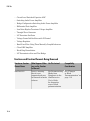
SimElectronics® Release Notes
How to Contact MathWorks
Latest news:
www.mathworks.com
Sales and services:
www.mathworks.com/sales_and_services
User community:
www.mathworks.com/matlabcentral
Technical support:
www.mathworks.com/support/contact_us
Phone:
508-647-7000
The MathWorks, Inc.
3 Apple Hill Drive
Natick, MA 01760-2098
SimElectronics® Release Notes
© COPYRIGHT 2008–2015 by The MathWorks, Inc.
The software described in this document is furnished under a license agreement. The software may be used
or copied only under the terms of the license agreement. No part of this manual may be photocopied or
reproduced in any form without prior written consent from The MathWorks, Inc.
FEDERAL ACQUISITION: This provision applies to all acquisitions of the Program and Documentation
by, for, or through the federal government of the United States. By accepting delivery of the Program
or Documentation, the government hereby agrees that this software or documentation qualifies as
commercial computer software or commercial computer software documentation as such terms are used
or defined in FAR 12.212, DFARS Part 227.72, and DFARS 252.227-7014. Accordingly, the terms and
conditions of this Agreement and only those rights specified in this Agreement, shall pertain to and
govern the use, modification, reproduction, release, performance, display, and disclosure of the Program
and Documentation by the federal government (or other entity acquiring for or through the federal
government) and shall supersede any conflicting contractual terms or conditions. If this License fails
to meet the government's needs or is inconsistent in any respect with federal procurement law, the
government agrees to return the Program and Documentation, unused, to The MathWorks, Inc.
Trademarks
MATLAB and Simulink are registered trademarks of The MathWorks, Inc. See
www.mathworks.com/trademarks for a list of additional trademarks. Other product or brand
names may be trademarks or registered trademarks of their respective holders.
Patents
MathWorks products are protected by one or more U.S. patents. Please see
www.mathworks.com/patents for more information.
Contents
R2015a
elec_getPowerLossSummary function to calculate and view
semiconductor switching device losses . . . . . . . . . . . . . . .
1-2
Nonlinear magnetization inductance with hysteresis option
for Nonlinear Inductor and Nonlinear Transformer
blocks . . . . . . . . . . . . . . . . . . . . . . . . . . . . . . . . . . . . . . . . . . . .
1-2
Schmitt Trigger block . . . . . . . . . . . . . . . . . . . . . . . . . . . . . . . .
1-3
Current Limiter block . . . . . . . . . . . . . . . . . . . . . . . . . . . . . . . .
1-3
Droop parameterization for DC-DC Converter block . . . . . .
1-3
Thermal port available for H-Bridge block . . . . . . . . . . . . . .
1-4
New examples . . . . . . . . . . . . . . . . . . . . . . . . . . . . . . . . . . . . . . .
1-4
R2014b
Averaged mode for stepper motor and driver blocks . . . . . .
2-2
Torque or force calculation option for FEM actuator
blocks . . . . . . . . . . . . . . . . . . . . . . . . . . . . . . . . . . . . . . . . . . . .
2-2
Nonzero threshold width in Switch blocks . . . . . . . . . . . . . .
2-2
Event-based variant of the N-Channel IGBT block . . . . . . . .
2-3
iii
Tabulated capacitance options for MOSFET and IGBT
blocks . . . . . . . . . . . . . . . . . . . . . . . . . . . . . . . . . . . . . . . . . . . .
2-4
Z pulse width change in Incremental Shaft Encoder block .
2-4
New examples . . . . . . . . . . . . . . . . . . . . . . . . . . . . . . . . . . . . . . .
2-4
R2014a
Unipolar Stepper Motor Driver block and half-stepping
option for stepper motor drivers . . . . . . . . . . . . . . . . . . . . .
3-2
Detent torque for stepper motors . . . . . . . . . . . . . . . . . . . . . .
3-2
Output capacitance for MOSFET and IGBT blocks . . . . . . . .
3-2
Lookup table definition of I-V relationship in IGBT and
Thyristor blocks . . . . . . . . . . . . . . . . . . . . . . . . . . . . . . . . . . .
3-3
Thyristor block that now models devices with higher leakage
currents . . . . . . . . . . . . . . . . . . . . . . . . . . . . . . . . . . . . . . . . . .
3-3
New examples . . . . . . . . . . . . . . . . . . . . . . . . . . . . . . . . . . . . . . .
3-3
R2013b
iv
Contents
Voltage-Controlled Oscillator block . . . . . . . . . . . . . . . . . . . .
4-2
Servomotor block that now permits parameterized torquespeed curve and optional iron losses . . . . . . . . . . . . . . . . .
4-2
Solar Cell block that now models solar cell arrays . . . . . . . .
4-2
New examples . . . . . . . . . . . . . . . . . . . . . . . . . . . . . . . . . . . . . . .
4-3
R2013a
Resistor with optional thermal noise . . . . . . . . . . . . . . . . . . .
5-2
Voltage and current sources with DC, AC, and noise
components . . . . . . . . . . . . . . . . . . . . . . . . . . . . . . . . . . . . . . .
5-2
Nonlinear charge model for N-Channel MOSFET, P-Channel
MOSFET, and N-Channel IGBT blocks . . . . . . . . . . . . . . . .
5-3
New examples . . . . . . . . . . . . . . . . . . . . . . . . . . . . . . . . . . . . . . .
5-3
R2012b
Single-pole and double-pole switch blocks . . . . . . . . . . . . . . .
6-2
Five new sensor blocks: PTC Thermistor, Pressure
Transducer, Resolver, Gyro, and Accelerometer . . . . . . . .
6-2
Nonlinear Transformer and Nonlinear Inductor blocks . . . .
6-3
DC-DC Converter block and Incandescent Lamp block . . . .
6-3
Unipolar Stepper Motor block and Stepper Motor block that
now account for iron losses . . . . . . . . . . . . . . . . . . . . . . . . .
6-4
New examples . . . . . . . . . . . . . . . . . . . . . . . . . . . . . . . . . . . . . . .
6-4
R2012a
Thermal Ports Available for Actuator Blocks and for Solar
Cell Block . . . . . . . . . . . . . . . . . . . . . . . . . . . . . . . . . . . . . . . .
7-2
v
Fully Differential Op-Amp Block . . . . . . . . . . . . . . . . . . . . . . .
7-2
Transmission Line Block . . . . . . . . . . . . . . . . . . . . . . . . . . . . .
7-2
Power Sensor Block . . . . . . . . . . . . . . . . . . . . . . . . . . . . . . . . .
7-2
Induction Motor Block Usability Enhancement . . . . . . . . . .
7-3
Controlled PWM Voltage Block Enhancement . . . . . . . . . . . .
7-3
Exponential Diode Block Now Models Charge Dynamics . . .
7-3
New Demos . . . . . . . . . . . . . . . . . . . . . . . . . . . . . . . . . . . . . . . . .
7-3
R2011b
Thermal Ports Available for Semiconductor Blocks . . . . . . .
8-2
New Operational Transconductance Amplifier Block . . . . . .
8-2
New Push-Pull Output Block . . . . . . . . . . . . . . . . . . . . . . . . . .
8-2
H-Bridge Block Enhancements . . . . . . . . . . . . . . . . . . . . . . . .
8-3
DC Motor Block Supports No-Load Current Data for Rotor
Damping . . . . . . . . . . . . . . . . . . . . . . . . . . . . . . . . . . . . . . . . .
8-3
New Demos . . . . . . . . . . . . . . . . . . . . . . . . . . . . . . . . . . . . . . . . .
8-4
R2011a
vi
Contents
Thermal Dependency Added to Semiconductor Blocks . . . .
9-2
New Demos . . . . . . . . . . . . . . . . . . . . . . . . . . . . . . . . . . . . . . . . .
9-2
R2010b
New Thyristor Block . . . . . . . . . . . . . . . . . . . . . . . . . . . . . . . .
10-2
New Multiplier Block . . . . . . . . . . . . . . . . . . . . . . . . . . . . . . .
10-2
Additional Exponential Diode Parameterization Options .
10-2
Channel Modulation Parameter Added for MOSFET
Blocks . . . . . . . . . . . . . . . . . . . . . . . . . . . . . . . . . . . . . . . . . .
10-2
Changes to the Bipolar Transistor Blocks . . . . . . . . . . . . . .
10-2
New Demos . . . . . . . . . . . . . . . . . . . . . . . . . . . . . . . . . . . . . . . .
10-3
R2010a
New Linear and Rotary Motors Defined in Terms of Flux .
11-2
New Potentiometer Block . . . . . . . . . . . . . . . . . . . . . . . . . . . .
11-2
Initial Conditions Tab Added for Logic Blocks . . . . . . . . . .
11-2
Changes in Block Parameterization . . . . . . . . . . . . . . . . . . .
Changes to the SPICE-Compatible Blocks . . . . . . . . . . . . . .
Changes to the Solar Cell Block . . . . . . . . . . . . . . . . . . . . .
11-2
11-2
11-3
New Demos . . . . . . . . . . . . . . . . . . . . . . . . . . . . . . . . . . . . . . . .
11-3
Functions and Function Elements Being Removed . . . . . . .
11-4
vii
R2009b
Actuators & Drivers Library Blocks . . . . . . . . . . . . . . . . . . .
New Generic Rotary Actuator Block . . . . . . . . . . . . . . . . . .
New Generic Linear Actuator Block . . . . . . . . . . . . . . . . . .
Improved Servomotor Block . . . . . . . . . . . . . . . . . . . . . . . .
12-2
12-2
12-2
12-2
New Abstracted Timer Block . . . . . . . . . . . . . . . . . . . . . . . . .
12-2
New Demos . . . . . . . . . . . . . . . . . . . . . . . . . . . . . . . . . . . . . . . .
12-2
R2009a
Actuators & Drivers Library . . . . . . . . . . . . . . . . . . . . . . . . .
New Piezo Motor Blocks . . . . . . . . . . . . . . . . . . . . . . . . . . .
Enhanced H-Bridge Block . . . . . . . . . . . . . . . . . . . . . . . . . .
13-2
13-2
13-2
Passive Devices Library . . . . . . . . . . . . . . . . . . . . . . . . . . . . .
New Switch Blocks . . . . . . . . . . . . . . . . . . . . . . . . . . . . . . .
New Resistor Block . . . . . . . . . . . . . . . . . . . . . . . . . . . . . . .
New Crystal Block . . . . . . . . . . . . . . . . . . . . . . . . . . . . . . .
Enhanced Variable Inductor and Variable Capacitor Blocks
13-2
13-2
13-2
13-3
13-3
Sources Library . . . . . . . . . . . . . . . . . . . . . . . . . . . . . . . . . . . .
Enhanced Solar Cell Block . . . . . . . . . . . . . . . . . . . . . . . . .
New Two-Input Dependent Source Blocks . . . . . . . . . . . . . .
13-3
13-3
13-3
SPICE-Compatible Semiconductors Library . . . . . . . . . . . .
Enhanced NMOS and PMOS Blocks . . . . . . . . . . . . . . . . . .
13-4
13-4
R2008b
New CMOS Logic Gate Blocks . . . . . . . . . . . . . . . . . . . . . . . .
viii
Contents
14-2
New Piezo Stack Block . . . . . . . . . . . . . . . . . . . . . . . . . . . . . .
14-2
New Relay Block . . . . . . . . . . . . . . . . . . . . . . . . . . . . . . . . . . .
14-2
New Fuse Block . . . . . . . . . . . . . . . . . . . . . . . . . . . . . . . . . . . .
14-2
New NMOS and PMOS Blocks . . . . . . . . . . . . . . . . . . . . . . . .
14-2
R2008a+
Product Introduction . . . . . . . . . . . . . . . . . . . . . . . . . . . . . . .
15-2
ix
R2015a
Version: 2.7
New Features
Bug Fixes
R2015a
elec_getPowerLossSummary function to calculate and view
semiconductor switching device losses
Checking dissipated power is useful for verifying that circuit components are
operating within their working envelopes. All components that constitute blocks
in the Semiconductor Devices library now have an internal variable called
power_dissipated, which represents the instantaneous power dissipated by the
component. When you log simulation data, the time-value series for this variable
represents the power dissipated by the component over time. You can view and plot this
data using the Simscape™ Results Explorer.
The elec_getPowerLossSummary function lets you calculate average losses for a block
over a period of time. Some blocks are composite components and therefore have more
than one power_dissipated variable, depending on their member components. For
example, the N-Channel IGBT block has separate power_dissipated logging nodes
for the MOSFET, PNP bipolar transistor, collector resistor, and emitter resistor member
components. In this case, the elec_getPowerLossSummary function sums all these
losses and provides the power loss value for the whole block.
To use the elec_getPowerLossSummary function, you have to enable simulation data
logging and run the simulation. For more information, see “Data Logging”.
The function takes a Simscape logging node as the first input argument. The second and
third input arguments are optional and represent the start and end of a time interval for
averaging the power losses. If you omit these two input arguments, the function averages
the power losses over the whole simulation time.
The function returns a MATLAB® table. The first column lists all blocks, within the
specified logging node, that have at least one power_dissipated variable, and the
second column lists the corresponding losses in watts.
For an example of using this function to determine the efficiency of a single-stage solar
converter, see Solar Power Converter.
Nonlinear magnetization inductance with hysteresis option for Nonlinear
Inductor and Nonlinear Transformer blocks
A new parameterization option for magnetization inductance, Magnetic Flux Density
Versus Magnetic Field Strength Characteristic with Hysteresis, is
available for the following blocks:
1-2
• Nonlinear Inductor
• Nonlinear Transformer
This option lets you define magnetic flux density as a function of both the magnetization
of the core and the history of the magnetic field strength, based on the Jiles-Atherton
model of hysteresis. See the block reference pages for details.
Schmitt Trigger block
The Schmitt Trigger block in the Logic sublibrary of the Integrated Circuits library
implements a behavioral model of Schmitt trigger. The block output logic level is HIGH
when the input rises above the High level input voltage value and does not go LOW
until the input falls below the lower-valued Low level input voltage value. This
implements a hysteresis characteristic between input and output of the block.
Current Limiter block
The Current Limiter block in the Semiconductor Devices library provides a behavioral
model of a current limiter. Use it to represent current limiting as found in some power
supplies and motor drives, and also to represent components that are used to limit inrush
current.
Droop parameterization for DC-DC Converter block
The DC-DC Converter block now has a new parameter, Droop parameterization,
which lets you choose between two options:
• By voltage droop with output current — Specify the absolute value of droop
by using the Output voltage droop with output current parameter. This is the
default option and the method available in previous releases.
• By percent voltage droop at rated load — Specify droop as a percentage at
rated load by using the Percent voltage droop at rated load parameter. This is
the new method. You specify a value, in percent, by which voltage drops compared to
the nominal output volage when supplying the rated load. The default is 2 percent.
The DC-DC Converter block now also has a new physical signal input port F and a
new tab, Faults, in the block dialog box, to let you simulate the DC supply failure and
converter failure. See the block reference page for details.
1-3
R2015a
Thermal port available for H-Bridge block
The H-Bridge block can now have an optional thermal port. By default, the thermal
port is not displayed. To expose the thermal port, right-click the H-Bridge block in your
model, and then from the context menu select Simscape > Block choices > Show
thermal port. This action displays the thermal port H on the block icon, and adds the
Temperature Dependence and Thermal port tabs to the block dialog box.
When the thermal port is visible:
• The heat generated by the bridge on-resistance and freewheeling diodes is added
to the thermal port. The thermal port has an associated thermal mass and initial
temperature that are set from the Thermal port tab.
• The bridge on-resistance and freewheeling diode resistance become functions
of temperature. The values for these resistances and the second measurement
temperature are defined from the Temperature Dependence tab. Resistance is
assumed to vary linearly between the two measurement temperatures. Extrapolation
is used for temperatures outside of this range except for when simulating in averaged
mode with discontinuous load current characteristics.
New examples
Examples introduced in this version are:
• Inductor With Hysteresis
• Analog Anti-Aliasing Filter
• Phase-Locked Loop
1-4
R2014b
Version: 2.6
New Features
R2014b
Averaged mode for stepper motor and driver blocks
A new parameter, Simulation mode, lets you select between Stepper and Averaged
modes, and is available for the following blocks:
• Stepper Motor
• Stepper Motor Driver
• Unipolar Stepper Motor
• Unipolar Stepper Motor Driver
If you select Averaged simulation mode for a motor-driver pair (that is, for a Stepper
Motor block and for the Stepper Motor Driver block that controls it, or for a Unipolar
Stepper Motor block and its Unipolar Stepper Motor Driver block), then the individual
steps are not simulated. This can be a good way to speed up simulation.
Averaged mode includes a slip estimator to predict whether the stepper motor would
have slipped if running in Stepping simulation mode. Upon detecting slip, the simulation
either continues (with or without a warning) or stops with an error, depending on your
setting for the Action on slipping parameter. If you simulate or predict slip, it is
generally a good practice to do some validation runs comparing Stepping and Averaged
modes before using the averaged model representation for simulation studies. See the
block reference pages for details.
Torque or force calculation option for FEM actuator blocks
FEM-Parameterized Rotary Actuator and FEM-Parameterized Linear Actuator blocks let
you either enter the torque or force data, as in previous releases, or calculate the torque
or force matrix from flux linkage information.
If the finite element package does not provide torque (force) and provides only flux data,
then you can let the block automatically calculate the torque (force) matrix from the
flux information. To select this option, set the Calculate torque matrix? or Calculate
force matrix? parameter (as appropriate) to Yes. The torque (force) matrix calculation
occurs at model initialization based on current block flux linkage information. See the
block reference pages for details.
Nonzero threshold width in Switch blocks
A new parameter, Threshold width, is available for the following blocks:
2-2
• SPST Switch
• SPDT Switch
• DPST Switch
• DPDT Switch
If the Threshold width parameter is set to zero (which is the default), the switch is
closed if the voltage presented at the vT control port exceeds the value of the Threshold
parameter.
If the Threshold width parameter is greater than zero, then switch conductance
G varies smoothly between off-state and on-state values. Defining a small positive
Threshold width can help solver convergence in some models, particularly if the
control port signal vT varies continuously as a function of other network variables.
However, defining a nonzero threshold width precludes the solver from making use of
switched linear optimizations. Therefore, if the rest of your network is switched linear,
MathWorks recommends that you set Threshold width to zero.
Event-based variant of the N-Channel IGBT block
In previous releases, the N-Channel IGBT block provided two ways of modeling an IGBT:
• As an equivalent circuit based on a PNP bipolar transistor and N-channel MOSFET
• By a lookup table approximation to the I-V (current-voltage) curve
These two methods are still available under the Full I-V and capacitance
characteristics block variant. In documentation, this variant is also referred to as the
detailed model. A new block variant, Simplified I-V characteristics and event-based
timing, provides a simplified, event-based model, which lets you represent the IGBT
more simply by using just the on-state I-V data corresponding to the gate voltage used
in your circuit. Switching between states is achieved by linearly ramping the collectoremitter voltage, which results in much faster simulation speed. Use the event-based
variant when the focus of the analysis is to understand overall circuit behavior rather
than to verify the precise IGBT timing or losses characteristics. For details, see EventBased IGBT Variant.
To select the desired variant, right-click the N-Channel IGBT block in your model. From
the context menu, select Simscape > Block choices, and then one of the following
options:
2-3
R2014b
• Full I-V and capacitance characteristics | No thermal port — Detailed model
that does not simulate the effects of generated heat and device temperature. This is
the default.
• Full I-V and capacitance characteristics | Show thermal port — Detailed
model with exposed thermal port.
• Simplified I-V characteristics and event-based timing | No thermal port —
Simplified event-based model, which also does not simulate the effects of generated
heat and device temperature.
• Simplified I-V characteristics and event-based timing | Show thermal port
— Simplified event-based model with exposed thermal port.
See the N-Channel IGBT block reference page for more information.
Tabulated capacitance options for MOSFET and IGBT blocks
N-Channel IGBT, N-Channel MOSFET, and P-Channel MOSFET blocks now have
additional options on the Junction Capacitance tab that let you parameterize the
charge model using table lookup.
In previous releases, these blocks provided two options for modeling capacitance: either
by specifying the junction capacitance values directly, or by letting the block derive them
from the input and reverse transfer capacitance values. Now each of these methods
allows you to enter either fixed capacitance values or tabulated values as a function of
the collector-emitter (drain-source) voltages. See the block reference pages for details.
Z pulse width change in Incremental Shaft Encoder block
In previous releases, there was no correlation between the Z pulse width and the
length of the A and B pulses. Therefore, although the block created a rising edge for the
synchronization Z pulse at the correct time, you could not use this block to synchronize
on the falling edge.
The Z pulse on time is now equal to the A and B pulse on times for a given rotational
speed, giving you the ability to decode on the rising edge and on the falling edge. For
existing models where just the rising edge of the pulse trains is used for decoding or
where the Z pulse is not used, there is no change in behavior.
New examples
Examples introduced in this version are:
2-4
• Behavioral IGBT Using Event-Based Equations
• Stepper Motor Averaged Mode
2-5
R2014a
Version: 2.5
New Features
Compatibility Considerations
R2014a
Unipolar Stepper Motor Driver block and half-stepping option for stepper
motor drivers
The new Unipolar Stepper Motor Driver block in the Drivers library represents a driver
specifically configured for use with the Unipolar Stepper Motor block. It connects the two
winding center-tap connections A0 and B0 to the positive supply with a voltage equal
to the value you provide for the Output voltage amplitude parameter. The A+, A-,
B+ and B- ports are then grounded in the appropriate sequence to create the stepping
motion. The block initiates a step each time the voltage at the PWM port rises above the
Enable threshold voltage.
The Stepper Motor Driver block now has an option to produce the output waveforms
required for half-stepping. By default, the driver operates in full-stepping mode, but
if you set the Stepping mode parameter to Half stepping, the driver generates
an intermediate state between the full steps, in which just one of the A or the B halfwindings is powered. As a result, the step size is half of the stepper motor’s full step size.
The new Unipolar Stepper Motor Driver block also has this option.
Detent torque for stepper motors
Both the Stepper Motor and the Unipolar Stepper Motor blocks now let you account for
the torque variation observed when the motor is unpowered and the shaft is rotated.
Detent torque is generated by the interaction of the permanent magnet flux and the
variation in reluctance as the teeth come in and out of alignment. The new Detent
torque parameter represents the amplitude of the sinusoidal torque variation, and the
corresponding term is added to the block equations. By default, the parameter value is
0, in which case detent torque is neglected in block computations. Legacy models are not
affected.
Output capacitance for MOSFET and IGBT blocks
A new block parameter lets you specify a value for output capacitance:
• For N-Channel IGBT, the Output capacitance, Coes parameter represents the
output capacitance applied across the collector-emitter ports.
• For N-Channel MOSFET and P-Channel MOSFET, the Output capacitance, Coss
parameter represents the output capacitance applied across the drain-source ports.
Modeling the output capacitance is generally important in signal processing applications,
as it has measurable effect on circuit behavior. For motor control applications the
3-2
effect is not as significant, because the other capacitances play a much bigger part in
setting turn-on and turn-off dynamics. However, if your datasheet provides a value for
output capacitance, you can enter it to increase the block fidelity. The default value is 0,
therefore legacy models are not affected.
Lookup table definition of I-V relationship in IGBT and Thyristor blocks
In previous releases, the Thyristor and N-Channel IGBT blocks have been represented
by an equivalent circuit constructed from other semiconductor blocks, such as bipolar
transistors and MOSFETs. Now both blocks have an additional representation option, by
a lookup table approximation of the on-state current-voltage curve. The main advantages
of using this option are increased simulation speed and ease of parameterization. See the
block reference pages for details.
Thyristor block that now models devices with higher leakage currents
In the Thyristor block represented by an equivalent circuit, the underlying model has
been enhanced with a pair of back-to-back diodes to allow a wider range of leakage
current variation. To help you parameterize your thyristor to match the manufacturer
datasheet, two test harnesses have been added to the SimElectronics® examples,
Thyristor Static Behavior Validation and Thyristor Dynamic Behavior Validation. See
the block reference page for more information.
Compatibility Considerations
To take advantage of the additional diodes, the mapping of the block parameters to
the equation parameters has been changed. Existing models may need fine-tuning
of parameter values to match the exact behavior with previous versions of the block,
particularly for parameters associated with dynamics.
New examples
Examples introduced in this version are:
• FEM-Parameterized Switched Reluctance Motor
• Automotive Electrical System
• Photovoltaic Generator Performance
• Microcontroller with GPIO, ADC and DAC Connections
3-3
R2014a
• Tabulate IGBT Switching Losses
3-4
R2013b
Version: 2.4
New Features
R2013b
Voltage-Controlled Oscillator block
The new Voltage-Controlled Oscillator block in the Integrated Circuits library models
abstracted behavior of a voltage-controlled oscillator (VCO). VCOs are basic building
blocks for RF transmitter and receiver devices, microprocessor clocks, and A-to-D
converters. The block models a behavioral representation of a VCO for simulation
efficiency.
You have two options for specifying frequency dependence on the input voltage:
• Linear — By specifying a coefficient for the rate of change of frequency with input
voltage.
• Tabulated — By using a lookup table and specifying a vector of input voltages and a
corresponding vector of VCO frequencies relative to the nominal frequency.
You also can model the time delay between a change in the input control voltage and the
oscillator frequency.
Servomotor block that now permits parameterized torque-speed curve
and optional iron losses
In previous versions, the Servomotor block allowed you to specify the torque-speed
envelope only as a set of speed data points and corresponding maximum torque values.
Now, you can also define the torque-speed envelope by specifying a maximum torque and
a maximum power instead of providing the tabulated torque-speed data.
The block now also accounts for iron losses due to eddy currents. The Torqueindependent electrical losses parameter is renamed to Fixed losses independent
of torque and speed, and the new Iron losses parameter lets you specify the iron
losses at the speed and torque at which efficiency is defined.
Solar Cell block that now models solar cell arrays
In previous versions, the Solar Cell block allowed you to model a single photovoltaic cell.
Now, you can model any number of solar cells connected in series using a single Solar
Cell block by setting the parameter Number of series cells to a value larger than one.
Internally the block still simulates only the equations for a single solar cell, but scales
up the output voltage according to the number of cells. This results in a more efficient
simulation than if equations for each cell were simulated individually.
4-2
If you want to model N cells in parallel, you can do so for single cells by scaling the
parameter values accordingly. That is, multiply short-circuit current, diode saturation
current, and solar-generated currents by N, and divide series resistance by N. To connect
solar cell blocks in parallel, where each block contains multiple cells in series, make
multiple copies of the block and connect accordingly.
New examples
Examples introduced in this version are:
• Solar Cell Power Curve
• Solar Power Converter
4-3
R2013a
Version: 2.3
New Features
Compatibility Considerations
R2013a
Resistor with optional thermal noise
The new Resistor block in the Passive Devices library models a linear resistor that
can optionally generate thermal noise current. The Gaussian noise is generated
using the new Random Number source block in the Simscape Foundation library.
The Repeatability parameter gives you the following options for noise control: not
repeatable, repeatable with a random seed, and repeatable with explicitly specified seed.
Compatibility Considerations
Legacy models, created in R2009b or earlier and not saved using a more recent version,
may need updating if they contain the SPICE Resistor block. If this is the case, upon
opening the model you will get a warning saying that the Resistor block does not have
a parameter named SCALE. To fix this issue, replace the resistor either with the new
Resistor block from the Passive Devices library, or with a new copy of the SPICE Resistor
block from the Additional Components/Spice-Compatible Components library.
Voltage and current sources with DC, AC, and noise components
Two new blocks have been added to the Sources library:
• Voltage Source block — Configurable as either AC or DC voltage source with optional
noise
• Current Source block — Configurable as either AC or DC current source with optional
noise
By default, both AC and DC components are set to 0 in each block. Define the AC/DC
voltage or current by specifying nonzero values for the appropriate parameters after
placing the block in your model.
If you enable the noise component, the Gaussian noise voltage or current, respectively,
is generated using the new Random Number source block in the Simscape Foundation
library. The Repeatability parameter gives you the following options for noise control:
not repeatable, repeatable with a random seed, and repeatable with explicitly specified
seed.
5-2
Nonlinear charge model for N-Channel MOSFET, P-Channel MOSFET, and
N-Channel IGBT blocks
The two MOSFET blocks now model gate junction capacitance as a fixed gate-source
capacitance and either a fixed or a nonlinear gate-drain capacitance. The IGBT block now
models gate junction capacitance as a fixed gate-emitter capacitance and either a fixed or
a nonlinear gate-collector capacitance.
If you select the nonlinear option for the charge-voltage linearity, then the gate-drain
charge relationship, or the gate-collector charge relationship, respectively, is defined by a
piecewise-linear function. For more information, see the respective block reference pages.
New examples
Examples introduced in this version are:
• Op-Amp with Noise
• Sigma Delta ADC with Noise
• IGBT Dynamic Characteristics
5-3
R2012b
Version: 2.2
New Features
Compatibility Considerations
R2012b
Single-pole and double-pole switch blocks
The Passive Devices library now contains a sublibrary, named Switches, with four new
blocks:
• The DPDT Switch block models a double-pole double-throw switch.
• The DPST Switch block models a double-pole single-throw switch.
• The SPDT Switch block models a single-pole double-throw switch.
• The SPST Switch block models a single-pole single-throw switch.
For each switch type, you have an option of modeling turn-on and turn-off delays, that is,
a delay between the point at which the voltage at the control port passes the threshold
and the point at which the switch opens or closes.
Five new sensor blocks: PTC Thermistor, Pressure Transducer, Resolver,
Gyro, and Accelerometer
Five new blocks have been added to the Sensors library:
• The Accelerometer block provides an abstract model of a MEMS accelerometer. The
acceleration at the mechanical translational port is mapped to either a voltage level or
the duty cycle of a PWM voltage across the electrical + and - ports. The output voltage
is limited according to the values that you provide for maximum and minimum
output voltage. Optionally, you can model sensor dynamics by adding a first-order
lag between the angular rate at the mechanical port and the corresponding voltage
applied to the electrical + and - ports.
• The Gyro block provides an abstract model of a MEMS gyroscope. The gyro provides
an output voltage that is proportional to the angular rotation rate presented at the
mechanical rotational port. The output voltage is limited according to the values
that you provide for maximum and minimum output voltage. Optionally, you can
model sensor dynamics by adding a first-order lag between the angular rate at the
mechanical port and the corresponding voltage applied to the electrical + and - ports.
• The PTC Thermistor block models a switching type positive temperature coefficient
(PTC) thermistor. This type of thermistor has a decreasing resistance with increasing
temperature, up to the Curie temperature. Above the Curie temperature, the
resistance increases very rapidly with increasing temperature. To represent a nonswitching linear PTC thermistor, use the Thermal Resistor block.
• The Pressure Transducer block models a generic pressure transducer that turns a
pressure measurement into a voltage. The output voltage is linearly proportional to
6-2
the pressure. If the pressure is less than zero, the block outputs zero volts. An input
pressure equal to the Pressure range parameter value results in an output voltage
equal to the Full-scale deflection parameter value. For higher pressures, the
output voltage remains at this Full-scale deflection value. You have three choices
of operation mode, which let you select between vacuum, atmospheric pressure, or
sealed-gauge reference pressure as the reference point for the pressure measurement.
You also have an option of approximating the sensor dynamics by a first-order lag.
• The Resolver block models a generic resolver, which consists of a rotary transformer
that couples an AC voltage applied to the primary winding to two secondary windings.
These secondary windings are physically oriented at 90 degrees to each other. As the
rotor angle changes, the relative coupling between the primary and the two secondary
windings varies. In the Resolver block model, the first secondary winding is oriented
such that peak coupling occurs when the rotor is at zero degrees, and therefore the
second secondary winding has minimum coupling when the rotor is at zero degrees.
Nonlinear Transformer and Nonlinear Inductor blocks
Two new blocks in the Passive Devices library let you take into account nonlinearities in
inductors and transformers due to magnetic saturation:
• The Nonlinear Inductor block represents an inductor with a core that is nonideal,
due to its magnetic properties or dimensions. You have multiple options of block
parameterization, including single inductance, single saturation point, magnetic
flux versus current characteristic, and magnetic field density versus magnetic field
strength characteristic.
• The Nonlinear Transformer block is based on the Nonlinear Inductor block and has
similar parameterization options, which let you model varying levels of nonlinearity.
You can parameterize the transformer winding either by combined primary and
secondary values, or by separate values for primary and secondary leakage resistance
and inductance.
DC-DC Converter block and Incandescent Lamp block
The new DC-DC Converter block in the Sources library represents a behavioral model
of a power converter. The power converter regulates voltage on the load side and the
required amount of power is drawn from the supply side to balance input power, output
power, and losses. Optionally, the converter can support regenerative power flow from
load to supply.
6-3
R2012b
The new Incandescent Lamp block in the Passive Devices library models an incandescent
lamp. The key characteristic of this block is that the resistance increases as the filament
warms up. The rate of heat loss from the filament is proportional to the filament’s
temperature difference to ambient. Optionally, you can simulate the fault dynamics by
specifying a simulation time at which the lamp fails.
Unipolar Stepper Motor block and Stepper Motor block that now account
for iron losses
The new Unipolar Stepper Motor block in the Rotational Actuators library represents a
stepper motor that has center taps on the two phase windings. All four half-windings are
identical. The block lets you simulate thermal effects, and also accounts for iron losses,
both in its electrical and thermal equations.
The existing Stepper Motor block has been enhanced to account for iron losses, as well.
It now has an additional thermal port HR, corresponding to the rotor and associated iron
losses. Additional parameters on the Electrical and Thermal Port tabs let you specify
magnetizing resistance, rotor thermal mass and initial temperature, and the percentage
of the magnetizing resistance associated with the magnetic path through the rotor.
Compatibility Considerations
If your existing model uses a Stepper Motor block with thermal ports exposed, the block
now has an additional thermal port HR (corresponding to the rotor and associated iron
losses). Leaving this new port unconnected results in a simulation-time error. If iron
losses associated with the rotor are not important, you can connect the HR port to an
Adiabatic Cup block.
New examples
Examples introduced in this version are:
• Automotive Alternator
• Nonlinear Inductor Characteristics
• Nonlinear Transformer Characteristics
• Parameterizing a TVS Diode
• Ultracapacitor With Converter
• Hybrid Vehicle Electrical Network
6-4
R2012a
Version: 2.1
New Features
R2012a
Thermal Ports Available for Actuator Blocks and for Solar Cell Block
All the blocks in the Rotational Actuators and Translational Actuators libraries, as well
as the Solar Cell block in the Sources library, can now have optional thermal ports. By
default, the thermal ports are not displayed. To expose the thermal port, right-click on
the relevant block in your model, and from the context menu select Simscape block
choices > Show thermal port. This action displays the thermal port H on the block
icon, and adds the Thermal port tab to the block dialog box.
This functionality is not always available for blocks in existing models, depending
on when the model was last saved. If you right-click on a block in a model saved in a
previous version, and the context menu item Simscape block choices does not appear,
make a new copy of the block from the SimElectronics library.
Fully Differential Op-Amp Block
The new Fully Differential Op-Amp block in the Integrated Circuits library models an
operational amplifier with fully differential output, that is, not referenced to ground.
The output common-mode voltage is controlled by the common-mode port cm. Internal
resistors set the nominal output common-mode voltage to be midway between the values
you provide for the positive and negative supply voltages. Applications include data
acquisition where inputs are differential, for example, sigma-delta converters.
The block provides a behavioral model of a fully differential operational amplifier.
It does not represent nonlinear effects, such as variation in gain with output voltage
amplitude, and the nonlinear nature of the output voltage-current relationship for large
load currents.
Transmission Line Block
The new Transmission Line block in the Passive Devices library lets you model a
transmission line either by using delays, or by a lumped parameter model. Use the delaybased models for better simulation performance at system level. The lossless delay-based
model represents an ideal transmission line.
Power Sensor Block
The new Power Sensor block in the Sensors library calculates the power taken by the
load connected across the + and - terminals under the assumption that only the load is
connected to the + terminal.
7-2
The sensor can return either instantaneous power, or power averaged over a fixed time
period. The latter option is useful when working with periodic current and voltage
waveforms, such as those associated with PWM control.
For an example of using this block, see the Flyback Converter demo.
Induction Motor Block Usability Enhancement
The usability of the Induction Motor block has been improved. In previous versions, when
setting Model parameterization to By motor ratings, you had to provide a value
for either the motor starting current or maximum torque. This group of parameters has
been removed, and instead the Rated RMS line current parameter value is used to
determine the total motor inductance. In existing models, if you used consistent values
for RMS starting (or locked rotor) line current and Rated RMS line current,
simulation results are the same as in previous versions.
Controlled PWM Voltage Block Enhancement
The Controlled PWM Voltage block has two new parameters, Pulse delay time and
Pulse width offset. Use these parameters to add a small turn-on delay and a small
turn-off advance. This can be helpful when fine-tuning switching times, to minimize
switching losses.
Exponential Diode Block Now Models Charge Dynamics
The Diode block now lets you model charge dynamics. The Exponential diode model
contains an additional set of parameters that let you either specify values for the transit
time and carrier lifetime directly, or calculate them using the peak reverse current and
reverse recovery time. This functionality is especially useful for applications such as
commutation diodes.
New Demos
Demos introduced in this version are:
• Controllable Phase Shifter
• Low-Pass Filter Using Operational Transconductance Amplifiers
• Fourth-Order Sallen-Key Lowpass Filter
7-3
R2012a
• Flyback Converter
7-4
R2011b
Version: 2.0
New Features
Compatibility Considerations
R2011b
Thermal Ports Available for Semiconductor Blocks
All the blocks in the Semiconductors library, as well as the Photodiode and LightEmitting Diode blocks in the Sensors library, can now have optional thermal ports. By
default, the thermal ports are not displayed. To expose the thermal port, right-click on
the relevant block in your model, and from the context menu select Simscape block
choices > Show thermal port. This action displays the thermal port H on the block
icon, and adds the Thermal port tab to the block dialog box.
Compatibility Considerations
In the N-Channel IGBT block, several new parameters on the Advanced tab have been
added, to better match the typical device datasheets. The Forward Early voltage, VAF
parameter, with the default value of 200 V, specifies the Forward Early voltage for the
PNP transistor. Previously the effect was not modeled. This means that existing models
will show small differences in the current-voltage relationship associated with the PNP
bipolar transistor, compared to the previous version. Additionally, the new Collector
resistance, RC and Emitter resistance, RE parameters have nonzero default values,
to improve the numeric efficiency of computations. If you want to preserve the simulation
results for the existing models, set Forward Early voltage, VAF to 1e10, Collector
resistance, RC to 0, and Emitter resistance, RE to 0.
New Operational Transconductance Amplifier Block
The Operational Transconductance Amplifier block, added to the Integrated Circuits
library, provides a behavioral representation of an operational transconductance
amplifier. A transconductance amplifier converts an input voltage into an output current.
Applications include variable frequency oscillators, variable gain amplifiers, and currentcontrolled filters. These applications are based on the fact that the transconductance gain
is a function of current flowing into the control current pin.
The block does not model the detailed transistor implementation. This results in faster
simulation, but the model is only valid when operating in the linear region, that is, where
the device input resistance, output resistance, and transconductance gain all depend
linearly on the control current, and are independent of input signal amplitude.
New Push-Pull Output Block
The Push-Pull Output block, added to the Integrated Circuits library, provides a
behavioral representation of a CMOS complementary output stage. To improve
8-2
simulation speed, the block does not model all the internal individual MOSFET devices
that make up the gate You can use this block to create a representative output currentvoltage relationship when defining an integrated circuit model behavior with Physical
Signal blocks from the Simscape Foundation library. For an example, see the Modeling
an Integrated Circuit demo.
H-Bridge Block Enhancements
The following enhancements have been implemented for the H-Bridge block:
• In Averaged mode, a new Load current characteristics parameter is available
with two options, Smoothed and Unsmoothed or discontinuous. The first option
assumes that the current is practically continuous due to load inductance, and
corresponds to the old block behavior. For cases where the current is not smooth, or
goes to zero between PWM cycles, use the Unsmoothed or discontinuous option,
and provide values for the new Total load series resistance, Total load series
inductance, and PWM frequency parameters. During simulation, the block uses
these values to calculate a more accurate value for H-bridge output voltage that
achieves the same average current as would be present if simulating in PWM mode.
• The Freewheeling mode parameter is now available not only in PWM mode, but
also in Averaged mode in cases where you select Unsmoothed or discontinuous
for the Load current characteristics parameter.
• An additional Freewheeling mode option, Via two semiconductor switches
and one freewheeling diode, controls the load by maintaining one high-side
bridge arm permanently on and using the PWM signal to toggle between enabling the
corresponding low-side bridge arm and the opposite high-side bridge arm. This means
that the block uses a freewheeling diode in parallel with a bridge arm, plus another
series bridge arm, to complete the dissipation circuit when the bridge turns off.
• The block dialog box has been reorganized using tabs, to improve usability.
DC Motor Block Supports No-Load Current Data for Rotor Damping
The DC Motor block has an additional option that lets you use no-load current data to
calculate a value for rotor damping. This is helpful when the manufacturer datasheet
does not provide an explicit rotor damping value.
The Rotor damping parameterization drop-down has been added to the Electrical
Torque tab of the block dialog box, with the following values:
8-3
R2011b
• By damping value — Specify a value for rotor damping directly, by using the Rotor
damping parameter on the Mechanical tab. This is the default.
• By no-load current — The block calculates rotor damping based on the values
that you specify for the No-load current and DC supply voltage when measuring
no-load current parameters. If you select this option, the Rotor damping
parameter is not available on the Mechanical tab.
Compatibility Considerations
Previously, if the Model parameterization parameter was set to By stall torque
& no-load speed or By rated power, rated speed & no-load speed, the block
did not take rotor damping into account. The new block equations always include rotor
damping, because it is now tied to no-load current. Therefore, rated speed and no-load
speed results for existing models using these options will be slightly different than in
previous versions if the model has a nonzero damping value.
If you wish to retain the original behavior, set the rotor damping to zero, and add an
external Rotational Damper block (from Simscape Foundation library) across the motor R
and C ports.
New Demos
Demos introduced in this version are:
• IGBT Thermal Characteristics
• Low-Cost Voltage Regulator
• Synchronous Buck Converter With Thermal Dynamics
• Thermal Characteristics of a Synchronous Buck Converter
8-4
R2011a
Version: 1.6
New Features
Compatibility Considerations
R2011a
Thermal Dependency Added to Semiconductor Blocks
Dialog boxes of most of the blocks in the Semiconductors library, and some related blocks,
now have a new tab, Temperature Dependence, which lets you specify additional
parameters to model the temperature dependence during simulation. For details, see
reference pages of the following blocks:
• Diode
• Light-Emitting Diode
• N-Channel IGBT
• N-Channel JFET
• N-Channel MOSFET
• NPN Bipolar Transistor
• Optocoupler
• Photodiode
• P-Channel JFET
• P-Channel MOSFET
• PNP Bipolar Transistor
Compatibility Considerations
In NPN and PNP Bipolar Transistor blocks, a new parameter, Collector-emitter
voltage at which h-parameters are defined, has been added. It serves to increase the
accuracy with which equation parameters are calculated from h-parameters, to better
capture current gain dependence on temperature. As a result, when you use Specify
from a datasheet for the Parameterization parameter, there is a small change in
the resulting transistor gain BF (calculated from the Forward current transfer ratio
h_fe parameter value), compared to the previous version of the block.
New Demos
Demos introduced in this version are:
• Torque Motor
• Schottky Barrier Diode Characteristics
• IGBT Characteristics
9-2
• Master-Slave J-K Flip-Flop
Change to an existing demo:
• The Finite Element Parameterized Solenoid demo now includes comparison with
the Simscape solenoid demo ssc_solenoid.mdl, to illustrate the effects of flux
saturation.
9-3
R2010b
Version: 1.5
New Features
R2010b
New Thyristor Block
The new Thyristor block, located in the Semiconductor Devices library, represents a
thyristor modeled using an NPN and a PNP transistor. The collector of each device is
connected to the base of the other device so as to give the P-N-P-N junction structure of a
thyristor.
New Multiplier Block
The new Multiplier block, located in the Integrated Circuits library, represents an
integrated circuit multiplier for physical signals. It allows you to multiply and divide
signals without switching to Simulink signals and back.
Additional Exponential Diode Parameterization Options
When using the Diode block, with the Diode model parameter set to Exponential, you
now have two additional options under Parameterization:
• Use an I-V data point and IS — Specify measured data at a single point on the
diode I-V curve in combination with the saturation current.
• Use an I-V data point and N — Specify measured data at a single point on the
diode I-V curve in combination with the emission coefficient.
See the block reference page for details.
Channel Modulation Parameter Added for MOSFET Blocks
The N-Channel MOSFET and P-Channel MOSFET blocks now have an additional
parameter, Channel modulation, L. The default value is 0 1/V. See the respective block
reference pages for details.
Changes to the Bipolar Transistor Blocks
The following changes have been implemented in the NPN Bipolar Transistor and PNP
Bipolar Transistor blocks:
• The Junction Capacitance tab has been renamed to Capacitance, and the two
existing parameters on it have been renamed:
10-2
• Base-emitter capacitance to Base-emitter junction capacitance
• Base-collector capacitance to Base-collector junction capacitance
• Two new parameters have been added to the Capacitance tab:
• Total forward transit time, representing the mean time for the minority
carriers to cross the base region from the emitter to the collector
• Total reverse transit time, representing the mean time for the minority carriers
to cross the base region from the collector to the emitter
• Default values for ohmic resistances have been changed to RB = 1 Ω, RC = 0.01 Ω, and
RE = 1e-4 Ω, to be consistent with the SPICE-compatible library.
New Demos
Demos introduced in this version are:
• Thyristor Static Behavior Validation
• Thyristor Dynamic Behavior Validation
• IC Multiplier Circuits
• Synchronous Buck Converter
10-3
R2010a
Version: 1.4
New Features
Compatibility Considerations
R2010a
New Linear and Rotary Motors Defined in Terms of Flux
Two new blocks represent models of a motor or actuator defined in terms of magnetic
flux:
• FEM-Parameterized Linear Actuator block, located in the Translational Actuators
library
• FEM-Parameterized Rotary Actuator block, located in the Rotational Actuators
library
New Potentiometer Block
The new Potentiometer block, located in the Passive Devices library, represents a
potentiometer, where the wiper position is controlled by the input physical signal.
Initial Conditions Tab Added for Logic Blocks
The dialog boxes of blocks in the Logic library now have an additional tab, Initial
Conditions, which lets you specify the output initial state (low or high). See the respective
block reference pages for details.
Changes in Block Parameterization
The ability to parameterize SimElectronics blocks by importing circuit data from a
SPICE netlist is no longer supported. As a result, using the netlist2sl function is no
longer recommended. See Parameterizing Blocks from Datasheets in the SimElectronics
User's Guide for alternative ways of block parameterization. Additional related changes
introduced in this version are:
• “Changes to the SPICE-Compatible Blocks” on page 11-2
• “Changes to the Solar Cell Block” on page 11-3
Changes to the SPICE-Compatible Blocks
The SPICE-compatible blocks have been moved to the Additional Components library.
They are organized in sublibraries according to function, for example, the SPICECompatible Sources library is now the Sources sublibrary of the Additional Components/
SPICE-Compatible Components library. The Resistor block, renamed SPICE Resistor,
and the Current-Controlled Switch and Voltage-Controlled Switch blocks have been
11-2
moved to the Passive Devices sublibrary of the Additional Components/SPICECompatible Components library.
Some of the blocks have been renamed so that their names start with the “SPICE” prefix.
The following table lists the old and new block names.
Old Name
New Name
Diode (SPICE)
SPICE Diode
NJFET
SPICE NJFET
NMOS
SPICE NMOS
NPN
SPICE NPN
PJFET
SPICE PJFET
PMOS
SPICE PMOS
PNP
SPICE PNP
Resistor
SPICE Resistor
There are no compatibility considerations as a result of renaming the SPICE-compatible
blocks and moving them to the Additional Components library. Your existing models will
be updated automatically when you open and save them in the new version.
Changes to the Solar Cell Block
In previous versions, the Solar Cell block had the option of using the SPICE Environment
Parameters block to set temperature. This is removed in R2010a to eliminate dependency
on the SPICE sublibrary. Also, the Solar Cell model now uses the regular Diode block
(exponential diode) rather than the SPICE Diode block.
Compatibility Considerations
There is an insignificant change in results, of the order of 1e-12, in the Solar Cell block
because of the diode replacement.
New Demos
Demos introduced in this version are:
• Finite Element Parameterized Solenoid
11-3
R2010a
• Circuit Level Switched Capacitor ADC
• Switching Audio Power Amplifier
• Bridge Configuration Switching Audio Power Amplifier
• Differential Pair Amplifier
• Low-Noise Bipolar Transistor Voltage Amplifier
• Triangle Wave Generator
• LC Transistor Oscillator
• Voltage-Controlled Oscillator with PI Control
• Voltage Regulator
• Band-Pass Filter Using Three Mutually-Coupled Inductors
• Class-E RF Amplifier
• Diode Ring Demodulator
• LC Transmission Line and Test Bridge
Functions and Function Elements Being Removed
11-4
Function or Function
Element Name
What Happens When
you use the Function
or Element?
Use This Instead
Compatibility
Considerations
netlist2sl
Issues a warning
that it is not
supported and may
be removed in future
releases
See Parameterizing
Blocks from
Datasheets in the
SimElectronics
User's Guide
for alternative
ways of block
parameterization
See “Changes
in Block
Parameterization” on
page 11-2
R2009b
Version: 1.3
New Features
Compatibility Considerations
R2009b
Actuators & Drivers Library Blocks
New features and changes introduced in this version are:
• “New Generic Rotary Actuator Block” on page 12-2
• “New Generic Linear Actuator Block” on page 12-2
• “Improved Servomotor Block” on page 12-2
New Generic Rotary Actuator Block
The Generic Rotary Actuator block models the torque-speed characteristics of a
generalized rotary actuator.
New Generic Linear Actuator Block
The Generic Linear Actuator block models the force-speed characteristics of a generalized
linear actuator.
Improved Servomotor Block
The Servomotor block now allows for the specification of additional parameters from
within the Block Parameters dialog box.
Compatibility Considerations
During simulation, the updated Servomotor block is backwards-compatible with models
defined in earlier versions of the software. However, the model generates a warning in
this version because the block dialog box supports additional unit options for torque and
speed data. To remove the warnings, open the block dialog box and select appropriate
units for the torque and speed data.
New Abstracted Timer Block
The new Timer block, located in the Integrated Circuits library, is an abstracted
behavioral model of a timer integrated circuit, such as the NE555.
New Demos
Demos introduced in this version are:
12-2
• Brushless DC Motor
• ARINC 429 Communications Link
• PNP Bipolar Transistor Characteristics
12-3
R2009a
Version: 1.2
New Features
R2009a
Actuators & Drivers Library
New features and changes introduced in this version are:
• “New Piezo Motor Blocks” on page 13-2
• “Enhanced H-Bridge Block” on page 13-2
New Piezo Motor Blocks
The Actuators & Drivers library now contains blocks for modeling piezoelectric travelling
wave motors. The library contains these new blocks:
• The Piezo Rotary Motor models the torque-speed characteristics of a rotary
piezoelectric motor.
• The Piezo Linear Motor models the force-speed characteristics of a linear piezoelectric
motor.
Enhanced H-Bridge Block
The H-Bridge block now provides the option to dissipate current via two freewheeling
diodes when the signal at the PWM port is low. To use this new option, select Via two
freewheeling diodes for the Freewheeling mode parameter.
Passive Devices Library
New features and changes introduced in this version are:
• “New Switch Blocks” on page 13-2
• “New Resistor Block” on page 13-2
• “New Crystal Block” on page 13-3
• “Enhanced Variable Inductor and Variable Capacitor Blocks” on page 13-3
New Switch Blocks
The Passive Devices library now contains Current-Controlled Switch and VoltageControlled Switch blocks to model electrical switches with hysteresis.
New Resistor Block
The Passive Devices library now contains a Resistor block to model a resistor as a
function of temperature and process data.
13-2
New Crystal Block
The Passive Devices library now contains a Crystal block to model the electrical
characteristics of a crystal resonator.
Enhanced Variable Inductor and Variable Capacitor Blocks
The Variable Inductor and Variable Capacitor blocks have the following enhancements:
• The Variable Inductor block now provides two options for the relationship between
the voltage across the device and the current through the inductor. The new
Equation parameter lets you select the voltage-current equation that you want.
• The Variable Capacitor block now provides two options for the relationship between
the current through the device and the voltage across the capacitor. The new
Equation parameter lets you select the current-voltage equation that you want.
Sources Library
New features and changes introduced in this version are:
• “Enhanced Solar Cell Block” on page 13-3
• “New Two-Input Dependent Source Blocks” on page 13-3
Enhanced Solar Cell Block
The Solar Cell block has the following enhancements:
• The block now provides the option to use an 8-parameter model that includes an
additional diode and a parallel resistor.
• The block now models temperature dependence.
New Two-Input Dependent Source Blocks
The SPICE-Compatible Sources library (in the Sources library) contains blocks for
modeling dependent sources with two controlling inputs. The library contains these new
blocks:
• PCCCS2 — Model polynomial current-controlled current source with two controlling
inputs
• PCCVS2 — Model polynomial current-controlled voltage source with two controlling
inputs
13-3
R2009a
• PVCCS2 — Model polynomial voltage-controlled current source with two controlling
inputs
• PVCVS2 — Model polynomial voltage-controlled voltage source with two controlling
inputs
SPICE-Compatible Semiconductors Library
New features and changes introduced in this version are:
Enhanced NMOS and PMOS Blocks
The NMOS and PMOS blocks now provide the option to model the electrical
characteristics of SPICE Level-3 MOSFET devices.
13-4
R2008b
Version: 1.1
New Features
R2008b
New CMOS Logic Gate Blocks
The Logic library (in the Integrated Circuits library) contains blocks for modeling CMOS
logic gates behaviorally. The library contains these new blocks:
• CMOS AND
• CMOS Buffer
• CMOS NAND
• CMOS NOR
• CMOS NOT
• CMOS OR
• CMOS XOR
New Piezo Stack Block
The Actuators & Drivers library now contains a Piezo Stack block to model the electrical
and force characteristics of a piezoelectric stacked actuator.
New Relay Block
The Passive Devices library now contains a Relay block to model the resistive and delay
characteristics of a relay controlled by an external physical signal.
New Fuse Block
The Passive Devices library now contains a Fuse block to model the following fuse
characteristics:
• Resistance.
• Rated current at which the fuse blows when exceeded for a specified amount of time.
New NMOS and PMOS Blocks
The SPICE-Compatible Semiconductors library (in the Semiconductor Devices library)
now contains NMOS and PMOS blocks to model the electrical characteristics of SPICE
Level-1 MOSFET devices.
14-2
R2008a+
Version: 1.0
New Features
R2008a+
Product Introduction
SimElectronics software is a modeling environment for the engineering design
and simulation of electronic and electromechanical systems within the Simulink®
environment.
Version 1.0 includes these features:
• A library of electronic and electromechanical blocks that model components such as:
• Sensors
• Semiconductors
• Actuators
For these blocks, you enter key parameter values directly from industry datasheets.
For more information about the available blocks, see SimElectronics Block Libraries.
• A function, netlist2sl, for creating library blocks that represent circuit data in a
SPICE netlist.
• Ability to convert SimElectronics models to C code.
For more information about code generation, see Code Generation in the Simscape
documentation.
• Access to linearization and steady-state solve capabilities in Simscape.
For more information about linearization, see Linearizing at an Operating Point in
the Simscape documentation.
For more information about how Simscape solves models, see How Simscape
Simulation Works in the Simscape documentation.
15-2