
1
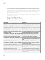
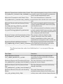
SimHydraulics® Release Notes
How to Contact MathWorks
Latest news:
www.mathworks.com
Sales and services:
www.mathworks.com/sales_and_services
User community:
www.mathworks.com/matlabcentral
Technical support:
www.mathworks.com/support/contact_us
Phone:
508-647-7000
The MathWorks, Inc.
3 Apple Hill Drive
Natick, MA 01760-2098
SimHydraulics® Release Notes
© COPYRIGHT 2006–2015 by The MathWorks, Inc.
The software described in this document is furnished under a license agreement. The software may be used
or copied only under the terms of the license agreement. No part of this manual may be photocopied or
reproduced in any form without prior written consent from The MathWorks, Inc.
FEDERAL ACQUISITION: This provision applies to all acquisitions of the Program and Documentation
by, for, or through the federal government of the United States. By accepting delivery of the Program
or Documentation, the government hereby agrees that this software or documentation qualifies as
commercial computer software or commercial computer software documentation as such terms are used
or defined in FAR 12.212, DFARS Part 227.72, and DFARS 252.227-7014. Accordingly, the terms and
conditions of this Agreement and only those rights specified in this Agreement, shall pertain to and
govern the use, modification, reproduction, release, performance, display, and disclosure of the Program
and Documentation by the federal government (or other entity acquiring for or through the federal
government) and shall supersede any conflicting contractual terms or conditions. If this License fails
to meet the government's needs or is inconsistent in any respect with federal procurement law, the
government agrees to return the Program and Documentation, unused, to The MathWorks, Inc.
Trademarks
MATLAB and Simulink are registered trademarks of The MathWorks, Inc. See
www.mathworks.com/trademarks for a list of additional trademarks. Other product or brand
names may be trademarks or registered trademarks of their respective holders.
Patents
MathWorks products are protected by one or more U.S. patents. Please see
www.mathworks.com/patents for more information.
Contents
R2015a
Variable-Displacement Hydraulic Machine (External
Efficiencies) block . . . . . . . . . . . . . . . . . . . . . . . . . . . . . . . . .
1-2
Valve opening dynamics in directional and pressure control
valves . . . . . . . . . . . . . . . . . . . . . . . . . . . . . . . . . . . . . . . . . . . .
1-2
Accumulator blocks with improved hard stops . . . . . . . . . . .
1-3
New examples . . . . . . . . . . . . . . . . . . . . . . . . . . . . . . . . . . . . . . .
1-3
R2014b
Flow Divider-Combiner block . . . . . . . . . . . . . . . . . . . . . . . . .
2-2
Variable Orifice Between Round Holes block . . . . . . . . . . . .
2-2
R2014a
Removal of laminar-turbulent zero-crossings in flow rate
equations . . . . . . . . . . . . . . . . . . . . . . . . . . . . . . . . . . . . . . . . .
3-2
Improvement of mass conservation for cylinders with fluid
compressibility . . . . . . . . . . . . . . . . . . . . . . . . . . . . . . . . . . . .
3-2
iii
Gate Valve equations change . . . . . . . . . . . . . . . . . . . . . . . . . .
3-2
R2013b
Cylinder Cushion block . . . . . . . . . . . . . . . . . . . . . . . . . . . . . .
4-2
Pressure-Compensated 3-Way Flow Control Valve block . . .
4-2
Pressure Reducing 3-Way Valve block . . . . . . . . . . . . . . . . . .
4-2
Nominal fluid density parameter for pump and motor
blocks . . . . . . . . . . . . . . . . . . . . . . . . . . . . . . . . . . . . . . . . . . . .
4-2
R2013a
iv
Contents
Flow Divider block . . . . . . . . . . . . . . . . . . . . . . . . . . . . . . . . . .
5-2
Fixed Orifice with Fluid Inertia block . . . . . . . . . . . . . . . . . .
5-2
Double-Acting Servo Cylinder block . . . . . . . . . . . . . . . . . . . .
5-2
Partially Filled Vertical Pipe LP block . . . . . . . . . . . . . . . . .
5-2
Spool Orifice Hydraulic Force block that now supports round
hole orifices . . . . . . . . . . . . . . . . . . . . . . . . . . . . . . . . . . . . . .
5-3
Improved conservation of mass for cylinders with fluid
compressibility . . . . . . . . . . . . . . . . . . . . . . . . . . . . . . . . . . . .
5-3
New examples . . . . . . . . . . . . . . . . . . . . . . . . . . . . . . . . . . . . . . .
5-3
R2012b
Journal Bearing Pressure-Fed block . . . . . . . . . . . . . . . . . . .
6-2
Fixed Orifice Empirical block . . . . . . . . . . . . . . . . . . . . . . . . .
6-2
Fixed-Displacement Motor (External Efficiencies) block . . .
6-2
Pneumo-Hydraulic Actuator block . . . . . . . . . . . . . . . . . . . . .
6-2
Counterbalance Valve and Hydraulically Operated Remote
Control Valve blocks . . . . . . . . . . . . . . . . . . . . . . . . . . . . . . .
6-3
New examples . . . . . . . . . . . . . . . . . . . . . . . . . . . . . . . . . . . . . . .
6-3
R2012a
Bug Fixes
R2011b
New Gate Valve Block . . . . . . . . . . . . . . . . . . . . . . . . . . . . . . . .
8-2
Swash Plate Block Enhancement . . . . . . . . . . . . . . . . . . . . . .
8-2
Segmented Pipe Block Enhancement . . . . . . . . . . . . . . . . . . .
8-2
v
R2011a
New Swash Plate Block . . . . . . . . . . . . . . . . . . . . . . . . . . . . . .
9-2
New Porting Plate Variable Orifice Block . . . . . . . . . . . . . . .
9-2
New Angle Sensor Block . . . . . . . . . . . . . . . . . . . . . . . . . . . . . .
9-2
Changes to SimHydraulics Demos . . . . . . . . . . . . . . . . . . . . . .
9-2
R2010b
New Jet Pump Block . . . . . . . . . . . . . . . . . . . . . . . . . . . . . . . .
10-2
Hydraulic Pipeline Block Enhancement . . . . . . . . . . . . . . . .
10-2
Changes to SimHydraulics Demos . . . . . . . . . . . . . . . . . . . . .
10-2
R2010a
vi
Contents
Simplified Blocks for Real-Time Simulation . . . . . . . . . . . .
11-2
Low-Pressure Blocks with Variable Elevations . . . . . . . . . .
11-2
Cartridge Valve Modeling Blocks . . . . . . . . . . . . . . . . . . . . .
11-2
Lubrication System Modeling Blocks . . . . . . . . . . . . . . . . . .
11-3
Centrifugal Pump Enhancement . . . . . . . . . . . . . . . . . . . . . .
11-3
Initial Piston Position in the Single-Acting Hydraulic
Cylinder Block . . . . . . . . . . . . . . . . . . . . . . . . . . . . . . . . . . .
11-3
Changes to SimHydraulics Demos . . . . . . . . . . . . . . . . . . . . .
11-4
R2009b
Additional 4-Way and 6-Way Directional Valve
Configurations . . . . . . . . . . . . . . . . . . . . . . . . . . . . . . . . . . .
12-2
Additional Low-Pressure Blocks . . . . . . . . . . . . . . . . . . . . . .
12-2
New Ball Valve with Conical Seat Block . . . . . . . . . . . . . . .
12-2
R2009a
New Low-Pressure Blocks Library . . . . . . . . . . . . . . . . . . . .
13-2
Changes to SimHydraulics Demos . . . . . . . . . . . . . . . . . . . . .
13-2
R2008b
Explicit Solvers Now Available for SimHydraulics Models
14-2
New Variable-Displacement Hydraulic Machine Block . . .
14-2
Improved Usability of the 4-Way Directional Valve Block .
14-2
Changes to SimHydraulics Demos . . . . . . . . . . . . . . . . . . . . .
14-2
vii
R2008a
Trimming Now Available for SimHydraulics Models . . . . .
15-2
New Cartridge Valve Insert and Hydraulic Cartridge Valve
Actuator Blocks . . . . . . . . . . . . . . . . . . . . . . . . . . . . . . . . . .
15-2
Additional Configurations for the Centrifugal Pump
Block . . . . . . . . . . . . . . . . . . . . . . . . . . . . . . . . . . . . . . . . . . .
15-2
Additional Fluids Available in the Hydraulic Fluid Block .
15-3
R2007b
Code Generation Now Available for SimHydraulics
Models . . . . . . . . . . . . . . . . . . . . . . . . . . . . . . . . . . . . . . . . . .
16-2
R2007a
viii
Contents
SimHydraulics Now Requires Simscape . . . . . . . . . . . . . . . .
17-2
Block Libraries Moved from SimHydraulics to Simscape . .
17-2
Sharing Models Using the Simscape Editing Modes . . . . . .
17-2
New SimHydraulics Blocks . . . . . . . . . . . . . . . . . . . . . . . . . .
17-2
Initial Conditions Added for Certain Blocks . . . . . . . . . . . .
17-2
Block Library Links Must Be Resolved . . . . . . . . . . . . . . . .
17-3
Changes to SimHydraulics Demos . . . . . . . . . . . . . . . . . . . . .
17-4
R2006b
Linearization Support . . . . . . . . . . . . . . . . . . . . . . . . . . . . . . .
18-2
New Solver Option Allows Starting Transient Analysis from a
Steady State . . . . . . . . . . . . . . . . . . . . . . . . . . . . . . . . . . . . .
18-2
Extended Functionality for Working with Physical Units .
18-2
New SimHydraulics Blocks . . . . . . . . . . . . . . . . . . . . . . . . . .
18-3
R2006a+
Product Introduction . . . . . . . . . . . . . . . . . . . . . . . . . . . . . . .
19-2
ix
R2015a
Version: 1.16
New Features
Bug Fixes
R2015a
Variable-Displacement Hydraulic Machine (External Efficiencies) block
The new Variable-Displacement Hydraulic Machine (External Efficiencies) block in
the Pumps and Motors library represents a reversible, variable positive-displacement
hydraulic machine with volumetric and mechanical efficiencies provided externally
to the block through physical signal ports EV and EM, respectively. The machine
displacement is controlled by the signal provided through the physical signal port C.
The block can work as a pump or a motor, depending on the direction of mechanical and
hydraulic power flow. To ensure continuity at the instance when the machine switches
its operational mode, the block implements a small transition region, defined by the
power threshold value. This transition region helps avoid a discontinuity and improve
numerical convergence.
Valve opening dynamics in directional and pressure control valves
The following blocks now have an additional parameter that lets you consider valve
opening dynamics:
• Check Valve
• Pilot-Operated Check Valve
• Hydraulically Operated Remote Control Valve
• Shuttle Valve
• Pressure Compensator
• Pressure Reducing 3-Way Valve
• Pressure Reducing Valve
• Pressure Relief Valve
The default block behavior is unchanged, that is, the valve sets its opening area directly
as a function of pressure. However, as the area changes instantaneously, so does the
flow equation, often by many orders of magnitude. Adding valve opening dynamics
provides continuous behavior that is more physically realistic, and is particularly helpful
in situations with rapid valve opening and closing.
If you set the new Opening dynamics parameter to Include valve opening
dynamics, two additional parameters become available:
• Opening time constant — The time constant for the first order response of the
valve opening.
• Initial area — The initial opening area of the valve.
1-2
The orifice passage area depending on pressure A(p) in the block equations then becomes
the steady-state area, calculated exactly as before, and the instantaneous orifice passage
area is calculated as
area.der = (steady-state area – area) / opening time constant,
with area = initial area at t = 0.
Use this feature in hydraulic simulations with the local solver for real-time simulation.
This feature is also helpful if you are interested in valve opening dynamics in variable
step simulations.
Accumulator blocks with improved hard stops
The Gas-Charged Accumulator and Spring-Loaded Accumulator blocks are each
equipped with two hard stops, used to restrict the fluid volume between zero and the full
fluid chamber capacity. In R2014b, these hard stops were modeled as absolutely plastic.
As a result, the fluid volume could drift below zero or above fluid chamber capacity in
some situations.
Starting in R2015a, the hard stop model in the accumulator blocks includes both a
stiffness term and a damping term to prevent the nonphysical values from occurring.
When the hard stops are modeled with finite stiffness and damping, it is still possible for
the fluid volume to become slightly negative or slightly greater than the fluid chamber
capacity. This represents the deflection in the hard stops.
As a result of these changes, both blocks now have a new parameter, Hard-stop
stiffness coefficient, which accounts for the stiffness term in the hard-stop equations.
The old parameter Penetration coefficient has been renamed to Hard-stop damping
coefficient, and some other block parameters have been renamed for clarity. See the
block reference pages for details.
When you upgrade from R2014b, the blocks in existing models automatically assume
a value of zero for the Hard-stop stiffness coefficient parameter value to preserve
the existing behavior. When you upgrade from R2014a or earlier, the blocks in existing
models automatically assume the new default values for the Hard-stop stiffness
coefficient and Hard-stop damping coefficient parameters.
New examples
The following example has been introduced in this version:
1-3
R2015a
• Hydraulic System with Priority Valve
1-4
R2014b
Version: 1.15
New Features
Bug Fixes
R2014b
Flow Divider-Combiner block
The new Flow Divider-Combiner block in the Flow Control Valves library models a valve
that divides the direct flow (incoming to port P) between two outlets, and also maintains
a specified proportion between return flows through ports A and B in the total flow rate
through port P. In other words, the valve works in two distinctive modes: flow divider
for direct flow and flow combiner for reverse flow. The existing Flow Divider block, also
available in the Flow Control Valves library, cannot be used as a flow combiner.
Variable Orifice Between Round Holes block
The new Variable Orifice Between Round Holes block in the Orifices library simulates
a variable orifice created by two interacting round holes, which can be of different
diameters. One hole is located in the sleeve, while the other is drilled in the case, with
the sleeve sliding along the case. Use this block in cartridge valve models.
2-2
R2014a
Version: 1.14
New Features
Bug Fixes
Compatibility Considerations
R2014a
Removal of laminar-turbulent zero-crossings in flow rate equations
Flow rate equations used in orifices, valves, local resistances, and low-pressure blocks
have been modified so that they no longer produce zero-crossings upon transition
between the laminar and turbulent regimes during simulation. This enhancement
increases simulation efficiency for hydraulic models. Numerical simulation results are
essentially the same.
Improvement of mass conservation for cylinders with fluid compressibility
The schematics of the cylinder and rotary actuator blocks no longer include the Hydraulic
Piston Chamber block. Instead, they are now using the updated hydro-mechanical
converter blocks from the Simscape™ Foundation library, which let you account for
fluid compressibility inside the converter block. For more information see the Simscape
Release Notes item, Hydro-mechanical converter blocks with fluid compressibility option.
Gate Valve equations change
The equations used to calculate the instantaneous area of the valve opening have
changed, to increase the fidelity of simulation. The area is now computed with the same
equation for the whole working range, 0 < h ≤ 2D:
A(h) = D2·( α/ 2 – sin(2α) / 4).
The angle α is computed as α = acos(1 – h / D) for the first half of the working range, 0 < h
≤ D, and as α = acos(h / D – 1) for the second half, D < h ≤ 2D.
Compatibility Considerations
Numerical simulation results for legacy models containing this block may change slightly
because of the change in the block equations.
3-2
R2013b
Version: 1.13
New Features
Bug Fixes
R2013b
Cylinder Cushion block
The new Cylinder Cushion block in the Hydraulic Cylinders library models a hydraulic
cylinder cushion, the device that decelerates the cylinder rod as it approaches the end of
stroke by restricting flow rate leaving the cylinder chamber.
Pressure-Compensated 3-Way Flow Control Valve block
The new Pressure-Compensated 3-Way Flow Control Valve block in the Flow Control
Valves library simulates a pressure-compensated 3-way flow control valve. The valve
includes a variable orifice and a normally closed pressure-control valve, connected in
parallel with the orifice. The purpose of the pressure-control valve is to maintain a
preset pressure differential across the orifice by diverting some flow from port A to tank
(through port R) if pressure differential exceeds the setting.
Pressure Reducing 3-Way Valve block
The new Pressure Reducing 3-Way Valve block in the Pressure Control Valves library
simulates a pressure reducing 3-way valve, sometimes also referred to as a pressure
reducing/relieving valve. The valve reduces inlet pressure to a preset value, similar to
a conventional pressure-reducing valve, but, additionally, starts working as a pressurerelief valve if the pressure continues to rise.
Nominal fluid density parameter for pump and motor blocks
The Nominal fluid density parameter lets you specify a value for fluid density, to
allow more flexibility and accuracy in modeling the working fluid. Previously, only fluid
viscosity was adjustable. The parameter has been added for the following blocks in the
Pumps and Motors library:
• Variable-Displacement Pressure-Compensated Pump
• Variable-Displacement Pump
• Variable-Displacement Motor
• Fixed-Displacement Pump
• Hydraulic Motor
4-2
R2013a
Version: 1.12
New Features
Bug Fixes
R2013a
Flow Divider block
The Flow Divider block simulates a hydraulic two-path flow divider, which consists of a
spring-centered spool installed in a case. The flow from the source enters the valve and
is split into two paths. Each path contains a fixed orifice and a variable orifice. The fixed
orifices must be precisely matched to divide flow in equal parts, or arranged in a certain
proportion if unequal division is required. The purpose of variable orifices is to maintain
a constant pressure drop across the fixed orifices, regardless of pressure fluctuations at
valve outlets. The load increase on any outlet causes the pressure drop across the spool
(and across fixed orifices) to change, and thus shift the spool. As a result, the passage
areas of variable orifices change until the pressure drop values across the fixed orifices
even out.
The Hydraulic System with Flow Divider example illustrates using a Flow Divider block
to split the flow equally between two consumers, represented by Orifice with Variable
Area Slot blocks.
Fixed Orifice with Fluid Inertia block
The Fixed Orifice with Fluid Inertia block models a hydraulic fixed orifice that accounts
for the fluid inertia, in addition to the static pressure loss. Fluid inertia plays a
noticeable role in orifices with large ratio of orifice length to the orifice hydraulic
diameter (L / DH), or in sharp-edged short orifices when the rate of change of flow rate
(fluid acceleration) is relatively large. The model accounts for the laminar and turbulent
flow regimes by monitoring the Reynolds number (Re) and comparing its value with the
critical Reynolds number (Recr). The transition between laminar and turbulent regimes
is assumed to be sharp and taking place exactly at Re=Recr.
Double-Acting Servo Cylinder block
The Double-Acting Servo Cylinder block models a hydraulic double-acting servo cylinder
implemented as a spring-centered plunger. Changing pressure at ports A and B shifts the
plunger from neutral position proportionally to the pressure differential. Use the servo
cylinder for control purposes.
Partially Filled Vertical Pipe LP block
The Partially Filled Vertical Pipe LP block models a vertical pipe connecting two tanks,
with the possibility that the top tank gets emptied, and therefore the top port of the
5-2
pipe can be exposed. The fluid level in the pipe then settles at some intermediate
position depending on pressures at both ports. The block models pipes with circular and
noncircular cross sections. The block accounts for friction losses, variable fluid level in
the pipe, and resulting variable heads at the ports.
Spool Orifice Hydraulic Force block that now supports round hole orifices
The Spool Orifice Hydraulic Force block simulates the steady-state axial hydraulic force
exerted on the spool by fluid flowing through the orifice. In previous releases, the orifice
was supposed to be rectangular. Now you have two parameterization options:
• A rectangular slot
• A round hole, or a set of round holes
The spool is assumed to be sharp-edged. The orifice width, or diameter, must be
considerably larger than the radial clearance between the spool and the sleeve.
Improved conservation of mass for cylinders with fluid compressibility
The four cylinder blocks that account for fluid compressibility have been changed to
include custom translational or rotational hydro-mechanical converters, instead of the
corresponding standard blocks from the Simscape Foundation library. The custom hydromechanical converters take into account pressure-induced density variations to give
increased accuracy. The affected blocks are:
• Double-Acting Hydraulic Cylinder
• Double-Acting Rotary Actuator
• Single-Acting Hydraulic Cylinder
• Single-Acting Rotary Actuator
New examples
The following example has been introduced in this version:
• Hydraulic System with Flow Divider
5-3
R2012b
Version: 1.11
New Features
Bug Fixes
R2012b
Journal Bearing Pressure-Fed block
The new Journal Bearing Pressure-Fed block in the Orifices library simulates the
hydraulic portion of a pressure-fed journal bearing. Connections A and B are hydraulic
conserving ports associated with the bearing inlet and outlet, respectively. The journal
radial displacement, which controls the bearing eccentricity, is imported through the
physical signal port J. The flow regime is assumed to be laminar due to small clearances.
Use this block in lubrication system simulation to assess the flow consumption through
the pressure-fed journal bearing.
Fixed Orifice Empirical block
The new Fixed Orifice Empirical block in the Orifices library models a fixed orifice in
hydraulic systems with data obtained from experimental testing. The data required
for characterization is the set of pressure differentials across the orifice, together
with associated flow rates determined for a particular fluid and temperature. The
block operates as a one-dimensional table lookup, with three interpolation and two
extrapolation methods.
Fixed-Displacement Motor (External Efficiencies) block
The new Fixed-Displacement Motor (External Efficiencies) block in the Pumps and
Motors library represents a fixed-displacement hydraulic motor with both mechanical
and volumetric efficiencies provided through the external physical signal ports.
Hydraulic losses are implemented as a leakage between hydraulic ports, while
mechanical losses are introduced through the friction imposed on the driving shaft. Both
the leakage and the friction are determined by the efficiency values.
Pneumo-Hydraulic Actuator block
The new Pneumo-Hydraulic Actuator block in the Cylinders library simulates a pneumohydraulic actuator, implemented as a double-acting cylinder with one side connected to
a hydraulic power supply and another side operated by pneumatic power. The hydraulic
part of the model accounts only for fluid consumption associated with the piston velocity.
The pneumatic part of the model is built with the ideal gas relationships. To simulate the
limit on the piston motion, the hard stop is included in the model. The piston effective
area is constant.
The model is suitable for building pneumo-hydraulic or hydro-pneumatic pumps,
intensifiers, and similar devices. You can simulate piston loading (such as inertia,
6-2
springs, friction) by modeling the load externally and connecting it to port L. Similarly,
simulate the heat exchange with the environment through the external thermal port E,
which corresponds to the gas in the chamber. Use blocks from the Simscape Foundation
library, such as Convective Heat Transfer, Conductive Heat Transfer, Thermal Mass,
and so on, depending on the actual system configuration.
Counterbalance Valve and Hydraulically Operated Remote Control Valve
blocks
Two new blocks extend the valve modeling capabilities:
• The Counterbalance Valve block in the Flow Control Valves library models an
internally-externally piloted counterbalance valve. The purpose of a counterbalance
valve is to control an overriding or suspended load by creating additional pressure in
the discharge line of a hydraulic actuator. The block is essentially a data-sheet-based
model that lets you characterize the valve by data usually provided in manufacturer
catalogs or data sheets.
• The Hydraulically Operated Remote Control Valve block in the Directional Valves
library represents a remote control valve where the valve control member (spool,
poppet, and so on) can be shifted from its initial position after pressure at the
pilot port exceeds the cracking pressure limit. The valve passage area is directly
proportional to pilot pressure. The model covers both normally closed and normally
open valve configurations.
New examples
The following example has been introduced in this version:
• Hydraulic System with Counterbalance Valve
6-3
R2012a
Version: 1.10.1
Bug Fixes
R2011b
Version: 1.10
New Features
R2011b
New Gate Valve Block
The new Gate Valve block in the Flow Control Valves library models a valve consisting
of a round orifice in the valve housing and a flat gate, which moves perpendicular to the
orifice axis. The orifice in the gate has the same diameter as the orifice in the housing. As
the gate moves, it opens or closes the valve passage. The flow rate through the valve is
proportional to the orifice opening and to the pressure differential across the orifice.
Swash Plate Block Enhancement
The Swash Plate block in the Pumps and Motors library now has the Piston offset
from the plate parameter, which lets you specify the offset between the piston tip and
the plate. The default value is 0, which corresponds to the block implementation in the
previous version.
Segmented Pipe Block Enhancement
Additional parameters in the Segmented Pipeline block let you specify the initial
condition for pressure inside the pipe segments. You have two options:
• The same initial pressure for all nodes — The initial pressure in all pipe
segments is the same, and is specified by the Initial pressure parameter value. This
is the default.
• Custom — Lets you specify initial pressure individually for each pipe segment, by
using the Initial pressure vector parameter. The vector size must be equal to the
number of pipe segments, defined by the Number of segments parameter value.
8-2
R2011a
Version: 1.9
New Features
Bug Fixes
R2011a
New Swash Plate Block
The new Swash Plate block in the Pumps and Motors library models a swash plate
mechanism used in axial-piston machines to convert translational motion of a piston
into rotational motion of a drive shaft. For details, see the block reference page and the
new Hydraulic Axial-Piston Pump with Load-Sensing and Pressure-Limiting Control
(sh_hydraulic_axial_piston_pump) demo.
New Porting Plate Variable Orifice Block
The new Porting Plate Variable Orifice block in the Pumps and Motors library models
a variable orifice located between the piston chamber and a crescent-shaped slot on a
porting plate in hydraulic axial-piston machines. For details, see the block reference page
and the new Hydraulic Axial-Piston Pump with Load-Sensing and Pressure-Limiting
Control (sh_hydraulic_axial_piston_pump) demo.
New Angle Sensor Block
The new Angle Sensor block in the Pumps and Motors library models an ideal angle
sensor with measuring range from zero to 360 degrees. With the sensor probe connected
to a mechanical rotational port, the output is a value between 0 and 2π, regardless
of the number of revolutions performed by the probe and direction of rotation. For an
example of block usage, see the new Hydraulic Axial-Piston Pump with Load-Sensing
and Pressure-Limiting Control (sh_hydraulic_axial_piston_pump) demo.
Changes to SimHydraulics Demos
The following demo has been added in Version 1.9:
Demo Name
Description
Hydraulic Axial-Piston Pump with Load-Sensing and
Pressure-Limiting Control
(sh_hydraulic_axial_piston_pump)
The demo models a test rig designed to
investigate interaction between an axialpiston pump and a typical control unit,
simultaneously performing the loadsensing and pressure-limiting functions.
To assure required accuracy, the model of
the pump must account for such features
as interaction between pistons, swash
9-2
plate, and porting plate, which makes it
necessary to build a detailed pump model.
9-3
R2010b
Version: 1.8
New Features
Bug Fixes
R2010b
New Jet Pump Block
The new Jet Pump block in the Pumps and Motors library models a jet liquid-liquid
pump operating with identical primary and secondary fluids containing no gas. For
details, see the block reference page and the new Well Jet Pump (sh_well_jet_pump)
demo.
Hydraulic Pipeline Block Enhancement
The Hydraulic Pipeline block now contains an additional parameter that lets you set the
initial pressure inside the pipe at the start of simulation. See the block reference page for
details.
Changes to SimHydraulics Demos
The following demos have been added in Version 1.8:
Demo Name
Description
Rotating Hydraulic Actuator
(sh_rotating_hydraulic_actuator)
Simulates a typical hydraulic cylinder
actuator used to operate friction clutches,
brakes and other devices installed on
rotating shafts.
Well Jet Pump
(sh_well_jet_pump)
Simulates a well jet pump installation,
consisting of a surface-mounted
centrifugal pump and a jet pump
installed in the well below water level.
10-2
R2010a
Version: 1.7
New Features
Bug Fixes
Compatibility Considerations
R2010a
Simplified Blocks for Real-Time Simulation
The following new blocks implement simplified models that reproduce only basic
functionality in exchange for better numerical efficiency:
• Single-Acting Hydraulic Cylinder (Simple) block represents a simplified version of a
single-acting hydraulic cylinder. The model assumes fluid compressibility, friction,
and leakages to be negligible. The hard stops are assumed to be fully inelastic, to
eliminate any possible oscillations at the end of the stroke.
• Double-Acting Hydraulic Cylinder (Simple) block represents a simplified version of a
double-acting hydraulic cylinder. The model assumes fluid compressibility, friction,
and leakages to be negligible. The hard stops are assumed to be fully inelastic, to
eliminate any possible oscillations at the end of the stroke.
• 4-Way Ideal Valve block represents a 4-way critically-centered valve. Initial openings
of all orifices are set to 0, which significantly simplifies the model.
• Valve Actuator block represents a simplified version of a valve actuator, built as a
first-order lag.
Use these blocks for real-time and HIL (hardware-in-the-loop) simulation, if such
simplifications are acceptable.
Low-Pressure Blocks with Variable Elevations
Additional blocks in the Low-Pressure Blocks library incorporate elevation information
and let you specify elevations as input signals, rather than as block parameters:
• Resistive Pipe LP with Variable Elevation block represents a hydraulic pipeline which
accounts for friction losses and port elevations.
• Hydraulic Pipe LP with Variable Elevation block represents a hydraulic pipeline with
resistive, fluid compressibility, and elevation properties.
Use these blocks for low-pressure system simulation in which the pipe ends change their
positions with respect to the reference plane.
Cartridge Valve Modeling Blocks
Two new blocks extend the cartridge valve modeling capabilities:
• Cartridge Valve Insert with Conical Seat block represents an insert of a hydraulic
cartridge valve consisting of a poppet interacting with the conical seat.
11-2
• Hydraulic 4-Port Cartridge Valve Actuator block represents double-acting hydraulic
valve actuator driven by four pressures. Use this block as a pilot actuator for cartridge
valves, as well as pilot-operated pressure and control valves, in applications where all
the forces, except spring and pressure forces, and flow consumption can be neglected.
There are also additional parameters in the Hydraulic Cartridge Valve Actuator block
that account for initial conditions and dynamic properties of the model. See the block
reference page for details.
Lubrication System Modeling Blocks
The following blocks have been added to facilitate modeling lubrication systems:
• Centrifugal Force in Rotating Cylinder block simulates centrifugal forces exerted by
fluid on a piston if the cylinder rotates about its symmetry axis. Such cylinders are
used in control mechanisms of various friction clutches, brakes, square-jaw positive
clutches, dog clutches, and so on. No inertial effects are considered in the model. In
other words, the angular velocity is assumed to be constant or changing at very low
speed.
• Rotating Pipe block models a hydraulic pipeline represented as a short bore drilled
through a shaft at some angle to its axis, or as a short pipe that connects actuator or
bearings, mounted on the shaft, with the channel inside the shaft. Such connections
are typical for lubrication systems and for hydraulically-operated clutches and
mechanisms. The shaft angular velocity is assumed to be constant or changing at very
low speed.
Centrifugal Pump Enhancement
The Centrifugal Pump block now contains additional parameters that let you simulate
operation at zero angular velocity. See the block reference page for details.
Initial Piston Position in the Single-Acting Hydraulic Cylinder Block
The Piston initial position parameter in the block dialog box has been renamed to
Initial distance between piston and cap, and the way it is used in the block output
has been changed.
In previous versions, the Piston initial position parameter let you specify the distance
that the piston is extended at the beginning of simulation by setting the piston initial
11-3
R2010a
position to any point within its stroke, but this value was not included in calculating the
rod displacement. In other words, the rod displacement output at the block's physical
signal port was with respect to the initial piston position.
In the current version, the Initial distance between piston and cap parameter value
is included in calculating the rod displacement output by the block:
xpst = x0 + xp
where
xpst
Rod displacement output by the physical signal port
x0
Initial distance between piston and cap
xp
Rod displacement with respect to its initial position
For details, see the block reference page.
Compatibility Considerations
The block output changes because of the new way it calculates rod displacement. It used
to start out at zero but now starts out at the initial position. If you have used this block
with nonzero initial position in your models, the block output will differ by this value:
xnew = x0 + xold
where
xnew
Rod displacement output by the physical signal port in the current version
xold
Rod displacement output by the physical signal port in the previous version
x0
Piston initial position value
Changes to SimHydraulics Demos
The following demos have been added in Version 1.7:
Demo Name
11-4
Description
Diesel Engine In-Line Injection System
Simulates an in-line multi-element
(sh_diesel_engine_in_line_injection_system) injection system. The objective of the
simulation is to investigate the entire
system operation.
Fuel Supply System with Variable Elevation
Simulates a three-tank fuel supply
(sh_fuel_supply_system_with_variable_elevations)
system where side tanks periodically
change elevations during the simulation
cycle.
Hydraulic Actuation System with Cartridge Valves
(sh_actuation_system_cartridge_valve)
Simulates a complex actuation system
equipped with cartridge valves.
Hydraulic Closed-Loop Actuator with Fixed-Step
Represents two versions of the same
Integration
closed-loop hydraulic actuator. In the
(sh_hydraulic_closed_loop_actuator_fixed_step)
second version, standard SimHydraulics®
blocks are replaced with their simplified
versions and the model is optimized for
fixed-step integration.
11-5
R2009b
Version: 1.6
New Features
Bug Fixes
R2009b
Additional 4-Way and 6-Way Directional Valve Configurations
Nine 4-way directional valve blocks and one 6-way directional valve block have been
added to the Directional Valves library, and the original 4-Way Directional Valve block
has been modified, to enable additional valve configurations. For more information, see
Modeling Directional Valves, as well as individual block reference pages.
Additional Low-Pressure Blocks
The following blocks have been added to the Low-Pressure Blocks library:
• Variable Head Two-Arm Tank block represents a tank with constant pressurization
and volume-dependent fluid level. The tank has two hydraulic ports and a physical
signal port, which exports the volume of fluid in the tank.
• Variable Head Three-Arm Tank block represents a tank with constant pressurization
and volume-dependent fluid level. The tank has three hydraulic ports and a physical
signal port, which exports the volume of fluid in the tank.
Both blocks account for the fluid level change caused by the volume variation, as well as
for pressure loss in the connecting pipes that can be caused by a filter, fittings, or some
other local resistance. You can specify pipeline diameter, pressure loss coefficient, and
elevation information for each hydraulic port separately.
New Ball Valve with Conical Seat Block
The new Ball Valve with Conical Seat block in the Flow Control Valves library models a
ball valve created by a spherical ball and a conical seat. The valve is characterized by the
ball diameter, cone angle, and orifice diameter.
12-2
R2009a
Version: 1.5
New Features
Bug Fixes
R2009a
New Low-Pressure Blocks Library
The Low-Pressure Blocks library, added in this release, contains five new blocks that
incorporate elevation information:
• Constant Head Tank block represents a tank where pressurization and fluid level
remain constant regardless of volume change. The block accounts for the fluid
level elevation with respect to the tank bottom, as well as for pressure loss in the
connecting pipe that can be caused by a filter, fittings, or some other local resistance.
• Variable Head Tank block represents a tank with constant pressurization and
volume-dependent fluid level. The block accounts for the fluid level change caused by
the volume variation, as well as for pressure loss in the connecting pipe that can be
caused by a filter, fittings, or some other local resistance.
• Resistive Pipe LP block represents a hydraulic pipeline which accounts for friction
losses and port elevations.
• Hydraulic Pipe LP block represents a hydraulic pipeline with resistive, fluid
compressibility, and elevation properties.
• Segmented Pipe LP block represents a hydraulic pipeline with resistive, fluid inertia,
fluid compressibility, and elevation properties.
These blocks enable additional applications, such as low-pressure fluid transportation
system simulation.
Changes to SimHydraulics Demos
The following demos have been added in Version 1.5:
Demo Name
Description
Water Supply System
(sh_water_supply_system)
The water supply system modeled in the demo
consists of three pumping stations located at 45,
25, and 30 m with respect to the reference plane,
respectively. All three stations are expected
to pump water in a tank located at 61 m. The
objective of simulation is to determine steadystate flow rates and pressures.
Fluid Transportation System with Three Tanks
(sh_three_tanks)
The demo illustrates a classical problem of
fluid transportation: to determine flow rates,
pressures, and fluid volumes in a system built
13-2
of three constant head tanks. The tanks are
located at different elevations and connected
with pipelines combined together in a common
node. The pipelines are simulated with the
Segmented Pipeline LP block, which accounts for
hydraulic losses, fluid inertia, and the head due
to different node elevations.
13-3
R2008b
Version: 1.4
New Features
Bug Fixes
R2008b
Explicit Solvers Now Available for SimHydraulics Models
Using explicit solvers has been implemented for models that include Simscape and
SimHydraulics blocks. For more information, see Setting Up Solvers for Physical Models
in the Simscape documentation.
New Variable-Displacement Hydraulic Machine Block
The Variable-Displacement Hydraulic Machine block, able to work as a pump or a motor,
enables modeling variable-efficiency machines based on manufacturer's data sheets. The
machine displacement is controlled by the signal provided through the physical signal
port C. The machine efficiency is simulated by implementing regime-dependable leakage
and friction torque based on the experimentally established correlations between the
machine efficiencies and pressure, angular velocity, and displacement.
Improved Usability of the 4-Way Directional Valve Block
The 4-Way Directional Valve block dialog box has been reorganized using tabs to improve
usability. Use the Initial openings tab to set all the initial orifice openings. The Basic
parameters tab contains the model parameterization options and the corresponding
parameters. The parameters themselves have not changed.
Changes to SimHydraulics Demos
The following demos have been added in Version 1.4:
Demo Name
Description
Hydraulic Drill-Ream Actuator
(sh_drill_ream_actuator)
The actuator is intended to drive a machine
tool working unit performing a sequence of
three technological operations: coarse drilling,
fine drilling, and reaming. The actuator
speed is controlled by one of three pressurecompensated flow control valves metering out
return flow from the cylinder. The selection
of an appropriate flow control is performed by
directional valves that are activated by a control
unit.
14-2
Front-Loader Actuation System
(sh_front_loader_actuation_system)
The model shows a simplified version of an
actuation system consisting of the lift and tilt
cylinders. Each of the cylinders is controlled by
an open center, 5-way, 3-position directional
valve. The valves are connected in series
through their unloading branch in such a way
that the system pump is unloaded when both
command levers are in neutral position. If either
tilt or lift command is applied, the unloading
path is closed.
Pipeline System with Centrifugal Pump
(sh_pipeline_system_centrifugal_pump)
The demo represents a typical pipeline system
with the centrifugal pump. The system is built
of three manifolds connected with hoses. The
combination of valves installed inside manifolds
allows flow rate to be directed through different
branches. The manifold models account for local
resistances, elbows, and cylindrical channels.
Also, the Variable Volume Chamber Test Rig (sh_variable_chamber_test_rig) demo
has been renamed to Variable Volume Piston Chamber Test Rig, and all the Variable
Volume Chamber blocks in it have been replaced with Piston Chamber blocks.
14-3
R2008a
Version: 1.3
New Features
Bug Fixes
R2008a
Trimming Now Available for SimHydraulics Models
Finding and managing operating points by trimming has been implemented for models
that include Simscape and SimHydraulics blocks. Simulink® Control Design™ product
is required for using this functionality. For more information, see Trimming Simscape
Models in the Simscape documentation.
New Cartridge Valve Insert and Hydraulic Cartridge Valve Actuator
Blocks
Two new blocks facilitate modeling cartridge valves:
• Cartridge Valve Insert block in the Directional Valves library represents an insert
of a hydraulic cartridge valve consisting of a poppet interacting with the sleeve seat.
The poppet position is determined by pressures at ports A, B, and X and force of the
spring. This is a structural model based on a Variable Orifice block and a Hydraulic
Cartridge Valve Actuator block, described below.
• Hydraulic Cartridge Valve Actuator block in the Valve Actuators library represents
a double-acting hydraulic valve actuator driven by three pressures. Use this block as
a pilot actuator for cartridge valves, as well as pilot-operated pressure and control
valves in applications where all the forces, except spring and pressure forces, and flow
consumption can be neglected.
Additional Configurations for the Centrifugal Pump Block
The Centrifugal Pump block represents a centrifugal pump of any type as a data-sheetbased model. Depending on data listed in the manufacturer's catalogs or data sheets for
your particular pump, you can now choose one of the following model parameterization
options:
• By approximating polynomial — Provide values for the polynomial coefficients.
These values can be determined analytically or experimentally, depending on the data
available. This is the default method, equivalent to the implementation available in
the previous release.
• By two 1D characteristics: P-Q and N-Q — Provide tabulated data of
pressure differential and brake power versus pump delivery characteristics. The
pressure differential and brake power are determined by one-dimensional table
lookup. You have a choice of three interpolation methods and two extrapolation
methods.
15-2
• By two 2D characteristics: P-Q-W and N-Q-W — Provide tabulated data
of pressure differential and brake power versus pump delivery characteristics at
different angular velocities. The pressure differential and brake power are determined
by two-dimensional table lookup. You have a choice of three interpolation methods
and two extrapolation methods.
Additional Fluids Available in the Hydraulic Fluid Block
The following predefined fluids have been added to the Hydraulic Fluid block:
• ISO VG 22 (ESSO UNIVIS N 22)
• ISO VG 46 (ESSO UNIVIS N 46)
• Brake fluid DOT3
• Brake fluid DOT4
• Brake fluid DOT5
• Water
See the block reference page for more information. The Examples section shows how you
can get information on the fluids and their properties.
15-3
R2007b
Version: 1.2.1
New Features
Bug Fixes
R2007b
Code Generation Now Available for SimHydraulics Models
Code generation has been implemented for models that include Simscape and
SimHydraulics blocks. For more information, see Code Generation in the Simscape
documentation.
16-2
R2007a
Version: 1.2
New Features
Bug Fixes
Compatibility Considerations
R2007a
SimHydraulics Now Requires Simscape
SimHydraulics now depends on and requires Simscape, the platform for all Physical
Modeling products, which includes common Physical Modeling utilities and block
libraries.
Block Libraries Moved from SimHydraulics to Simscape
The Foundation and Utilities block libraries that used to be included in SimHydraulics
(V1.0 and V1.1) are now part of Simscape product.
Sharing Models Using the Simscape Editing Modes
When working with SimHydraulics models, you now have a selection of two Simscape
editing modes that allow full or restricted editing of models.
• The Restricted mode requires SimHydraulics software to be installed, but does not
require a license. It allows you change a limited set of model parameters, but not the
blocks or connections, in a SimHydraulics model.
• The Full mode requires SimHydraulics software to be installed with a license. It
allows you to change anything in a SimHydraulics model.
New SimHydraulics Blocks
The new blocks introduced in Version 1.2 are listed below:
• Centrifugal Pump
• Single-Acting Rotary Actuator
• Double-Acting Rotary Actuator
• Hydraulic Single-Acting Valve Actuator
• Hydraulic Double-Acting Valve Actuator
• Valve Hydraulic Force
• Spool Orifice Hydraulic Force
Initial Conditions Added for Certain Blocks
Several blocks now have a parameter that specifies the initial condition for use in
computing the block's initial state at the beginning of a simulation run. Note that some of
17-2
these blocks, which used to be included in SimHydraulics (V1.0 and V1.1), are now part
of Simscape product. The following is a complete list of blocks where you can specify an
initial condition through the block dialog box:
• Gas-Charged Accumulator
• Spring-Loaded Accumulator
• Constant Volume Chamber
• Variable Volume Chamber
• Fluid Inertia
• Inertia
• Mass
• PS Integrator
• Rotational Spring
• Translational Spring
For details, see the block reference pages.
Compatibility Considerations
In this version, there is a difference in the way the initial conditions are computed, and
as a result, the blocks that have an initial condition parameter work differently than
they used to in the previous version.
Block Library Links Must Be Resolved
All SimHydraulics blocks in your models must now have resolved block library links.
You can neither disable nor break these library links. This is a global requirement
of Simscape modeling environment. Consult the Simscape documentation for further
details.
Compatibility Considerations
If you have an existing SimHydraulics model with disabled or broken links from
SimHydraulics blocks to the SimHydraulics block library, you must restore all the broken
block library links for your model to be valid.
17-3
R2007a
If you have disabled or broken the SimHydraulics library link for blocks that you have
customized and want to keep these modified blocks in your model, you must move these
modified blocks to your own custom library or libraries, then copy the block instances
that you need to your model.
You must still restore the block link to its parent library, whether that parent library is
SimHydraulics or your own.
Changes to SimHydraulics Demos
The following demos have been added in Version 1.2:
Demo Name
Description
Hydraulic Actuator with Two-Chamber
Snubbers
(sh_actuator_with_2_chamber_snubbers)
The reciprocal actuator demonstrated in this
model is equipped with snubbers (cushions) on
both sides of the cylinder.
Digital Hydraulic Actuator
(sh_digital_hydraulic_actuator)
The digital hydraulic actuator consists of three
double-acting cylinders mounted in the same
shell and interconnected through the hard stops.
Hydraulic Actuator with Load-Sensing Variable- The circuit demonstrates usage of a load-sensing
Displacement Pump
and pressure-limiting unit in a conventional
(sh_hydraulic_actuator_load_sensing_pump)
reciprocal system with variable load on the
forward stroke.
Hydraulic Actuator with Telescopic Cylinder
The actuator is built around a telescopic
(sh_hydraulic_actuator_telescopic_cylinder)
hydraulic cylinder, which is equipped with three
rods interacting with each other through hard
stops.
Closed-Circuit Reciprocal Actuator
The demo illustrates a closed-circuit
(sh_hydraulic_closed_circuit_reciprocal_actuator)
electrohydraulic actuator driven by a variablevelocity electrical motor.
Power-Assisted Steering Mechanism
The model represents a simplified version of a
(sh_hydraulic_power_assisted_steering) power-assisted steering mechanism showing all
its major parts.
Hydraulic System with Servo-Valve
The demo represents the model of a two-stage
(sh_hydraulic_system_with_servo_valve) servo-valve with a 4-way, 3-position spool valve
in the power stage and a flapper-nozzle amplifier
in the pilot stage.
17-4
Hydraulic Transmission with Secondary Control The system demonstrates usage of the so-called
(sh_hydraulic_transmission_secondary_control)
secondary control in hydrostatic transmissions
with a variable-displacement motor.
Hydrostatic Transmission with Shuttle Valve
The circuit demonstrates a hydrostatic
(sh_hydrostatic_transmission_shuttle_valve)
transmission with a shuttle valve in the control
unit.
Hydraulic Circuit with Load-Sensing Velocity
Control
(sh_load_sensing_velocity_control)
The circuit is equipped with the load-sensing
velocity regulator installed between the pump
and directional valve.
Oscillating Hydraulic Mechanism
(sh_oscillating_hydraulic_mechanism)
The oscillating hydraulic mechanism consists of
a single-acting hydraulic rotary actuator, winch,
flow control valve, two-position electrohydraulic
valve, and power and control units.
Reciprocal Actuator with Counterbalance Valves The actuator is built of a double-acting
(sh_reciprocal_actuator_cntrb_valves) cylinder, directional valve, flow control,
block of counterbalance valves, power unit,
replenishment arrangement, and a control unit.
Sequencing Circuit with Rotary Actuators
The sequence circuit is based on four check
(sh_sequencing_circuit_rotary_actuators)valves installed in both pressure and return
lines of the second rotary actuator.
The following demos that used to be in SimHydraulics 1.1 are now part of Simscape
product:
Demo Name
Description
Simple Mechanical System
(ssc_simple_mechanical_system)
This model is built of both rotational and
translational mechanical blocks to illustrate
their use in a system.
Mechanical System with Translational Friction The demo illustrates a mass loaded with a
(ssc_mechanical_system_translational_friction)
spring and viscous damper.
Mechanical System with Translational Hard
The demo illustrates two masses interacting
Stop
through a hard stop.
(ssc_mechanical_system_translational_hardstop)
Mechanical Rotational System with Stick-Slip
Motion
(ssc_rot_system_stick_slip)
This model demonstrates a mechanical
rotational system, where a load is driven by a
velocity source with a friction element between
17-5
R2007a
them, and stick-slip motion is developed in the
regions of constant velocities.
Linkage Mechanism
(ssc_linkage_mechanism)
17-6
The model demonstrates the use of the Lever
block in a linkage mechanism.
R2006b
Version: 1.1
New Features
Bug Fixes
R2006b
Linearization Support
The Simulink linmod and dlinmod commands create continuous- or discrete-time linear
time-invariant (LTI) state-space models from Simulink models. You can now use these
commands to generate an LTI state-space model from a model containing SimHydraulics
components.
There are two basic ways linmod and dlinmod can be used, and the behavior of
linearization differs depending on which method is chosen. If linmod(mdl) is called
(that is, the arguments for time, state, and input are not provided), then consistent initial
conditions are solved for in the same way as on the first step of a simulation. If you call
linmod(mdl, t, x, u), it is particularly important to provide it with a consistent
state to linearize about. For more information, see Linearizing at an Operating Point in
the Simscape User's Guide.
New Solver Option Allows Starting Transient Analysis from a Steady
State
A new solver option allows you to specify that simulation starts from a steady state.
Steady state means that the system variables are no longer changing with time.
If you select the Start simulation from steady state check box in the Solver block
dialog, the solver attempts to find the steady state that would result if the inputs to the
system were held constant for a sufficiently large time, starting from the initial state
obtained from the initial conditions computation. Although the solver tries to find the
particular steady state resulting from the given initial conditions, it is not guaranteed to
do so. All that is guaranteed is that if the steady-state solve succeeds, the state found is a
steady state (within tolerance). Simulation then starts from this steady state.
Note If the simulation fails at or near the start time when you use the Start simulation
from steady state option, consider clearing the check box and simulating with the plain
initial conditions computation only.
Extended Functionality for Working with Physical Units
Version 1.1 provides the following commands that help you specify the physical units for
your system:
• pm_adddimension
18-2
• pm_addunit
• pm_getunits
Unit names are defined in the pm_units.m file, which is shipped with the product.
You can open this file to see how the physical units are defined, and also as an example
when adding your own units. This file is located in the directory matlabroot\toolbox
\physmod\pm_util\pm_util.
Use the pm_getunits command to get an up-to-date list of units currently defined in
your unit registry. Use the pm_adddimension and pm_addunit commands to define
additional units.
New SimHydraulics Blocks
The new blocks introduced in Version 1.1 are listed below:
• Annular Orifice
• Cylinder Friction
• Reservoir
• Elbow
• Pipe Bend
• T-junction
• Gradual Area Change
• Sudden Area Change
• Variable-Displacement Motor
• Variable-Displacement Pump
• Shuttle Valve
• PS Product
• PS Divide
18-3
R2006a+
Version: 1.0
New Features
R2006a+
Product Introduction
SimHydraulics software is a modeling environment for the engineering design and
simulation of hydraulic power and control systems within Simulink and MATLAB®.
It is based on the Physical Network approach and contains a comprehensive library of
hydraulic blocks, as well as one-dimensional translational and rotational mechanical
elements and utility blocks.
SimHydraulics software key features are:
• Enables modeling and simulation of hydraulic power and control systems in Simulink
• Provides intuitive and convenient description of multidomain models based on
physical networks
• Includes a library of hydraulic components, such as pumps, valves, accumulators, and
pipelines, that account for effects such as fluid compressibility, turbulence transition,
and fluid inertia
• Provides foundation library of hydraulic building blocks, as well as fundamental
mechanical and mathematical elements, to enable efficient extension and
customization of models
• Provides customizable library of hydraulic fluids
SimHydraulics software employs a network approach to model building. Components in
the network correspond to physical elements, such as pumps, motors, valves, etc. The
lines that join the components correspond to physical connections that transmit power
between components. Unlike traditional Simulink block diagrams, these connections are
non-directional and do not require the user to resolve the causality of the system while
building the model. SimHydraulics libraries contain more than 75 models of hydraulic
and mechanical components. All the models were developed to be easily characterized
by data normally available in manufacturer's catalogs or data sheets. Building a model
of a system is analogous to assembling the actual physical system with off-the-shelf
components. The end result is a hydraulic circuit schematic in concurrence with ISO
1219 Fluid Power Standard.
SimHydraulics limitations are:
• Explicit solvers are not currently supported. Only the following solvers are supported:
ode15s, ode23t, and ode14x.
• A SimHydraulics physical network should not exist within a Simulink algebraic
loop. This means that you should not directly connect an output of a PS-Simulink
19-2
Converter block to an input of a Simulink-PS Converter block of the same physical
network.
• Code generation is not currently supported.
19-3


![libsbml[5pt] Developer`s Manual](http://vs1.manualzilla.com/store/data/005677524_1-a4aef53ff9933c16603010582721c07c-150x150.png)