1
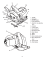
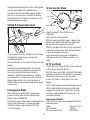
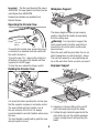
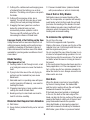
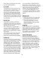
Circular Saw
Instruction Manual
764272-00
Consistent with our continuing product
development, improvements may have
been made which render the contents of this
instruction manual slightly different to the
product received.
CS718-AE
Congratulations!
On the purchase of your Black &
Decker circular saw.
To ensure the best results from your
circular saw please read these safety and
usage instructions carefully.
If you have any questions or queries after
reading this user manual please do not
hesitate to call our Service Centre.
Service Department:
U.A.E
PO.Box 5420
Dubai
Tel: 971-4-7028234
Fax: 971-4-2822765
2
3
6
15
1
16
14
2
10
9
8
7
11
13
12
4
5
3
1. Handle
2. Namplate
3. On/Off Switch
4. Lock-Off button
5. Depth of cut adjusting
lever
6. Cordset
7. Lower guard
8. Hex head bolt
9. Shoe/base plate
R&D
10. Outer flange
11. Blade
12. Fence
13. Fence locking screw
14. Bevel adjustment
lever
15. Upper guard
16. Front handle
General Safety Rules
electric shock.
d) Do not abuse the cord. Never use
the cord for carrying, pulling or
unplugging the power tool. Keep
cord away from heat, oil, sharp
edges or moving parts. Damaged or
entangled cords increase the risk of
electric shock.
d) When operating a power tool
outdoors, use an extension cord
suitable for outdoor use.Use of a
cord suitable for outdoor use reduces
the risk of electric shock.
Warning! Read all instructions. Failure
to follow all instructions listed below may
result in electric shock, fire and/or serious
injury. The term “power tool” in all of the
warnings listed below refers to your mains
operated (corded) power tool or battery
operated (cordless) power tool.
SAVE THESE INSTRUCTIONS.
1) Work area
a) Keep work area clean and well lit.
Cluttered and dark areas invite
accidents.
b) Do not operate power tools in
explosive atmospheres, such as in
the presence of flammable liquids,
gases or dust. Power tools create
sparks which may ignite the dust
perfumes.
c) Keep children and bystanders
away while operating a power tool.
Distractions can cause you to lose
control.
3) Personal safety
a) Stay alert, watch what you are
doing and use common sense when
operating a power tool. Do not use a
power tool while you are tired or
under the influence of drugs, alcohol
or medication. A moment of
inattention while operating power
tools may result in serious personal
injury.
b) Use safety equipment.
Always wear eye protection.
Safety equipment such as dust mask,
non-skid safety shoes, hard hat, or
hearing protection used for
appropriate conditions will reduce
personal injuries.
c) Avoid accidental starting.
Ensure the switch is in the off
position before plugging in.
Carrying power tools with your finger
on the switch or plugging in power
tools that have the switch on invites
accidents.
d) Remove any adjusting key or
wrench before turning the power tool
on. A wrench or a key left attached to
a rotating part of the power tool may
result in personal injury.
2) Electrical safety
a) Power tool plugs must match the
outlet. Never modify the plug in any
way. Do not use any adapter plugs
with earthed (grounded) power
tools. Unmodified plugs and matching
outlets will reduce risk of electric
shock.
b) Avoid body contact with earthed
or grounded surfaces such as pipes,
radiators, ranges and refrigerators.
There is an increased risk of electric
shock if your body is earthed or
grounded.
c) Do not expose power tools to rain
or wet conditions. Water entering a
power tool will increase the risk of
4
e) Do not overreach. Keep proper
footing and balance at all times. This
enables better control of the power
tool in unexpected situations.
f) Press properly. Do not wear loose
clothing or jewellery.
Keep your hair, clothing and gloves
away from moving parts. Loose
clothes, jewellery or long hair can be
caught in moving parts.
g) If devices are provided for the
connection of dust extraction and
collection facilities, ensure these
are connected and properly used.
Use of these devices can reduce dust
related hazards.
for misalignment or binding of
moving parts, breakage of parts
and any other condition that may
affect the power tools operation.
If damaged, have the power tool
repaired before use. Many accidents
are caused by poorly maintained
power tools.
f) Keep cutting tools sharp and
clean. Properly maintained cutting
tools with sharp cutting edges are
less likely to bind and are easier to
control.
g) Use the power tool, accessories
and tool bits etc., in accordance
with these instructions and in the
manner intended for the particular
type.
4) Power tool use and care
a) Do not force the power tool.
Use the correct power tool for your
application. The correct power tool
will do the job better and safer at the
rate for which it was designed.
b) Do not use the power tool if the
switch does not turn it on and off.
Any power tool that cannot be
controlled with the switch is
dangerous and must be repaired.
c) Disconnect the plug from the
power source before making any
adjustments, changing accessories,
or storing power tools. Such
preventive safety measures reduce
the risk of starting the power tool
accidentally.
d) Store idle power tools out of the
reach of children and do not allow
persons unfamiliar with the power
tool or these instructions to operate
the power tool. Power tools are
dangerous in the hands of untrained
users.
e) Maintain power tools. Check
5) Service
a) Have your power tool serviced by
a qualified repair person using only
identical replacement parts.This will
ensure that the safety of the power
tool is maintained.
Additional Safety Instructions
a) Young children and the infirm.
This appliance is not intended for use
by young children or infirm persons
without supervision. Young children
should be supervised to
ensure that they do not play with
this appliance.
b) Replacement of the supply cord.
If the supply cord is damaged, it must
be replaced by the manufacturer or
an authorised Black & Decker Service
Centre in order to avoid a hazard.
5
Additional Safety Instructions
For Circular Saw
Depth of Cut
Scale
Warning! The use of any accessory or
attachment, other than recommended in
this instruction manual, may present a risk
of personal injury.
Warning! Your saw is designed for
use with wood cutting blades with a max
operating speed above 4800 RPM.
Warning! Do Not use blades with a
Max operating speed below this speed.
Do not use saw blades which are deformed
or cracked.
Do not use saw blades made from High
Speed Steel.
Do not use saw blades which do not
comply with the characteristics specified
within this manual.
Do not stop the saw with lateral pressure on
the blade.
Do not lock the moveable guard in the open
position.
Ensure the moveable guard operates freely
without jamming.
Always ensure the retraction mechanism of
the guard operates correctly prior to using
the saw each time.
Always remove the plug of the saw from
the mains supply before making any
adjustments or maintenance to the saw.
Preparing Your Saw
Setting the Depth of Cut.
Remove the plug of the saw from the electricity
supply.
Unlock the depth of cut lock adjustment by
lifting the depth of cut locking lever.
The depth of cut can now be adjusted by lifting
the rear section of the saw body.
6
Depth of Cut
Lever
A scale referring to the depth of cut is provided
as a guide. It is located between the top guard
and the rear handle.
Note, the scale is a guide only and where an
accurate depth of cut is required, the actual
depth of cut should be measured with a rule.
AfterPIC
the desired
setting is achieved, lock the
C
depth of cut adjustment by pushing the depth
of cut locking lever downwards.
Where the saw blade is required to cut fully
through the work piece, the blade should be
set to a depth of cut 3 - 5 mm greater than the
work piece.
Fitting and Adjusting the Parallel
Fence
Your CS718 Circular Saw includes a parallel
fence. This assists in the sawing of a straight
line, parallel to the edge of the work piece.
To fit and adjust the parallel fence proceed as
follows:
Remove the plug of the saw from the
electricity supply.
Loosen the parallel locking screw at the front of
the saw shoe.
Slide the parallel fence into the slot under the
locking screw.
Slide the parallel fence towards the cutting
blade until the desired measurement is
obtained between the tooth of the cutting blade
and the inner edge of the parallel fence.
To ensure the correct setting, always make a
test cut on a scrap piece of timber to ensure
the parallel fence has been correctly set to the
measurement you require.
To Remove the Blade
Setting the Bevel Adjustment
hex head bolt
Outer Flange
Saw Blade
Adjust the depth of cut of the saw to
maximum.
Fully retract the lower guard.
With the lower guard fully open, depress the
spindle lock button and rotate the blade until
the spindle lock engages the spindle.
With the spindle lock button firmly depressed,
rotate the locking screw with the hex spanner
in an anti-clockwise direction.
Fully remove the screw and small washer.
Fully remove the outer flange and the saw
blade.
PIC G
Your circular saw can cut angles up to 45 Deg.
To adjust the angle of your circular saw
proceed as follows:
Remove the plug of the saw from the electricity
supply.
Unlock the bevel adjustment by turning the
lock lever clockwise. Move the saw around
the bevel scale until the desired angle is
indicated. Tighten the bevel lock by rotating
anti-clockwise. To ensure the correct setting,
always make a test cut on a scrap piece of
timber. Make any fine adjustments to the angle
if necessary.
To Fit the Blade
Ensure the inner flange is fitted to the saw and
is free of any sawdust / dirt etc.
With the lower guard fully retracted fit the blade
ensuring the arrow on the blade is in the same
direction as the arrow on the saw cover.
Ensure the blade is sitting flat on the inner
flange.
Fit the outer flange ensuring the flange is clean.
Fit the blade locking screw and washer and
engage the spindle lock. Tighten the locking
screw by rotating with the hex spanner in a
clockwise direction.
Changing the Blade
Before fitting any blade to the circular saw
ensure the max safe working speed of the
blade is above 4800RPM.
Remove the plug of the saw from the electricity
supply. Never attempt to change the blade
while the circular saw is plugged into the
electricity supply.
Replacement Blades
The CS718 Circular Saw is designed to fit the
following blade.
Blade
184mm (71/4”)
Bore diameter
20mm
No load speed (min)
4800 RPM
7
Important: The No Load Speed of the saw is
4800 RPM. The saw blade to be fitted must be
rated higher than 4800 RPM.
Workpiece Support
Replacement blades are available from
Black & Decker.
45
30
15
Operating the Circular Saw
On/Off
Trigger
The above diagram shows proper sawing
position. Note that the hands are kept away
from the cutting area.
Warning! It is important to support the
work properly and to hold the saw firmly to
prevent loss of control which could cause
personal injury.
Place the work with the good side, the one on
which appearance is most important – down.
The saw cuts upward, so any splintering will
be on the work face that is up when you saw it.
Lock off
button
To operate the circular saw, ensure the plug is
B
connected PIC.
to a standard
electrical outlet with
SWITCH DET AIL
the switch turned on.
To turn the saw “On”, depress the small lock
off button on the side of the handle and then
squeeze the On/Off trigger .
To stop the saw, release the trigger switch.
Improper Support
Holding the Circular Saw
45
30
15
45
30
15
45
30
15
PIC H
It is important when operating
the circular saw
that the operator is always in complete control.
The saw is fitted with two handles, one at
the rear and one at the front. It is always
recommended to use both handles when using
the saw.
The front handle is positioned to guide the saw
along the path to be cut.
A. Sagging or improper lifting of the cut off
piece will cause pinching of the blade.
B. Cutting through material supported at the
outer ends only. As the material weakens
it sags, closing the kerf and pinching the
blade.
8
C. Cutting off a cantilevered overhanging piece
of material from the bottom in a vertical
direction. The falling cut-off piece can pinch
the blade.
D. Cutting off long narrow strips (as in
ripping). The cut off strip can sag or twist
closing the kerf and pinching the blade.
E. Snagging the lower guard on a surface
below the material being cut can
momentarily reduce operator control.
The saw can lift partially out of the cut
increasing the chance of blade twist.
C. Pressure treated timber (material treated
with preservatives or anti-rot chemicals).
Use of Dull or Dirty Blades
Dull blades cause increased loading of the
saw. To compensate, an operator will usually
push harder which further loads the unit and
promotes the twisting of the blade in the kerf.
Worn blades may also have insufficient body
clearance which increases the chance of
binding and increased loading.
To minimise the splintering:
Improper Depth of Cut Setting on the Saw
Do not force the saw.
Cut from the opposite side if possible.
Clamp a thin piece of scrap over the top of the
material to be cut. Cut through both the scrap
and the original work piece.
Do not overload the saw. Allow the saw to run
at close to full speed during operation. Do not
force the saw into the work piece. The tool will
cut better when the saw is running at close to
full speed.
In the event where the saw has been used in a
heavy application, or if the saw appears to be
hot, run the saw for two minutes unloaded to
allow the motor to cool. Always ensure the air
intake vents are clear.
Using the saw with an excessive depth of cut
setting increases loading on the unit and susceptibility to twisting of the blade in the kerf.
It also increases the surface area of the blade
available for pinching under conditions of kerf
close down.
Blade Twisting
(Misalignment in Cut)
A. Pushing harder to cut through a knot, a nail
or a hard grain area can cause the blade to
twist.
B. Trying to turn the saw in the cut (trying to
get back on the marked line) can cause
blade twist.
C. Extended reach or operating saw with poor
control (operator off balance), can result in
twisting the blade.
D. Changing hand grip or body position while
cutting can result in blade twist.
E. Backing unit up to clear blade can lead to
twist if not done carefully.
Kick Back
When the blade is pinched or bound tightly
by the kerf closing down, the blade stalls
and the motor reaction drives the unit rapidly
backwards towards the operator.
If the blade becomes twisted or misaligned
in the cut, the teeth at the back edge of the
blade can dig into the top surface of the wood
causing the blade to climb out of the kerf and
jump backwards towards the operator.
Using dull blades or improperly supported
work will increase the tendency for kickback.
Wet timber, green timber or pressure treated
Materials that Require Extra Attention
A. Wet timber.
B. Green timber (material freshly cut or not kiln
dried).
9
timber require special attention during cutting
operation to prevent kickback.
Line Guide
The right side of the notch in the front of the
shoe is the guide for straight 90 degree cuts.
The left side of the notch is for 45 degree
bevel cuts. The cutting guide notch gives an
approximate line of cut since different blade
types and thickness alter the line cut. Always
make sample cuts in scrap timber to obtain the
actual line cut. To minimize splintering, cut the
good side down.
General Cuts
When starting a cut always hold the saw
handle with one and and the front handle with
the other. Never force the saw but maintain a
light and continuous pressure.
After completing the cut, allow the saw to
come to a complete stop. When cutting is
interrupted, resume cutting by allowing the
blade to reach full speed and then re-entering
the cut slowly.
When cutting across the grain, the fibres of
the wood have a tendency to lift and tear.
Moving the saw slowly minimises this effect.
Pocket Cuts
Disconnect the plug from the power supply
before making any adjustments. Set the depth
adjustment based on the thickness of the
material to be cut. Tilt the saw forward with
the cutting guide notch on the line drawn for
the cut. Raise the lower guard by using the lift
lever. With the blade barely above the material
to be cut, start the saw and allow the blade to
come to full speed. Gradually lower the blade
into the material being cut using the front end
of the shoe as a pivot point. When the blade
starts cutting, release the lower guard. When
the shoe is resting flat on the surface being
cut, proceed cutting in a forward direction to
the end of the cut. Allow the blade to come to a
full stop before removing it form the cut. Never
pull the saw backward since the blade will
climb out of the cut and kick back will occur.
Turn the saw around and finish the cut in a
normal manner, sawing forward. Use a jigsaw
or a handsaw to finish the cut in the corners, if
required.
Maintenance
1. All bearings are sealed. They are lubricated
for life and need no further maintenance.
2. The brushes are designed to give you
several years of use. If they ever need
replacement return the tool to the nearest
service centre for repair.
Important
To assure product SAFETY and RELIABILITY,
repairs, maintenance and adjustment including
brush inspection and replacement) should be
performed by authorised service centres or
other qualified service organisations, always
using identical replacement parts.
Service Information
Black & Decker offers a full network of
company owned and authorized service
locations throughout the country. All Black &
Decker Service Centers are staffed with trained
personnel to provide customers with efficient
and reliable power tool service. Whether you
need technical advice, repair, or genuine
factory replacement parts, contact the Black
& Decker location nearest you. To find your
local service location, refer to the yellow page
directory under “Tools—Electric” or call:
U.A.E on 971-4-7028234
10
Accessories
CAUTION: The use of any nonrecommended accessory such as dado sets,
molding cutters or abrasive wheels may be
hazardous.
Technical Data
Model:
Watts
No load speed
Volts AC/Frquency
Max depth of cut 90o
Max depth of cut 45o
Blade diameter
Blade bore
CS718-AE
1500 W
4800 RPM
230V 50Hz
63 mm
43 mm
185 mm
20 mm
11