1
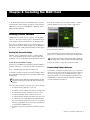
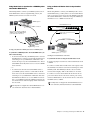
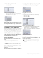
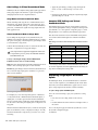
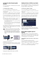
VENUE MADI Option Card For VENUE Systems Avid 2001 Junipero Serra Boulevard Daly City, CA 94014-3886 USA Product Information For company and product information, visit us on the web at www.avid.com Guide Part Number 9321-62043-00 REV " /10 Legal Notices Communication Statement This guide is copyrighted ©2010 by Avid Technology, Inc., with all rights reserved. Under copyright laws, this guide may not be duplicated in whole or in part without the written consent of Avid Technology, Inc. NOTE: This equipment has been tested and found to comply with the limits for a Class B digital device, pursuant to Part 15 of the FCC Rules. These limits are designed to provide reasonable protection against harmful interference in a residential installation. This equipment generates, uses, and can radiate radio frequency energy and, if not installed and used in accordance with the instructions, may cause harmful interference to radio communications. However, there is no guarantee that interference will not occur in a particular installation. If this equipment does cause harmful interference to radio or television reception, which can be determined by turning the equipment off and on, the user is encouraged to try and correct the interference by one or more of the following measures: • Reorient or locate the receiving antenna. • Increase the separation between the equipment and receiver. • Connect the equipment into an outlet on a circuit different from that to which the receiver is connected. • Consult the dealer or an experienced radio/TV technician for help. 003, 96 I/O, 96i I/O, 192 Digital I/O, 192 I/O, 888|24 I/O, 882|20 I/O, 1622 I/O, 24-Bit ADAT Bridge I/O, AudioSuite, Avid, Avid DNA, Avid Mojo, Avid Unity, Avid Unity ISIS, Avid Xpress, AVoption, Axiom, Beat Detective, Bomb Factory, Bruno, C|24, Command|8, Control|24, D-Command, D-Control, D-Fi, D-fx, D-Show, D-Verb, DAE, Digi 002, DigiBase, DigiDelivery, Digidesign, Digidesign Audio Engine, Digidesign Intelligent Noise Reduction, Digidesign TDM Bus, DigiDrive, DigiRack, DigiTest, DigiTranslator, DINR, D-Show, DV Toolkit, EditPack, Eleven, HD Core, HD Process, Hybrid, Impact, Interplay, LoFi, M-Audio, MachineControl, Maxim, Mbox, MediaComposer, MIDI I/O, MIX, MultiShell, Nitris, OMF, OMF Interchange, PRE, ProControl, Pro Tools M-Powered, Pro Tools, Pro Tools|HD, Pro Tools LE, QuickPunch, Recti-Fi, Reel Tape, Reso, Reverb One, ReVibe, RTAS, Sibelius, Smack!, SoundReplacer, Sound Designer II, Strike, Structure, SYNC HD, SYNC I/O, Synchronic, TL Aggro, TL AutoPan, TL Drum Rehab, TL Everyphase, TL Fauxlder, TL In Tune, TL MasterMeter, TL Metro, TL Space, TL Utilities, Transfuser, Trillium Lane Labs, Vari-Fi Velvet, X-Form, and XMON are trademarks or registered trademarks of Avid. Xpand! is Registered in the U.S. Patent and Trademark Office. All other trademarks are the property of their respective owners. Product features, specifications, system requirements, and availability are subject to change without notice. Canadian Compliance Statement: This Class B digital apparatus complies with Canadian ICES-003. Cet appareil numérique de la classe B est conforme à la norme NMB-003 du Canada. Australian Compliance Guide Part Number 9322-62043-00 REV " /10 Documentation Feedback We are always looking for ways to improve our documentation. If you have comments, corrections, or suggestions regarding our documentation, email us at [email protected]. Avid European Compliance Communications and Safety Regulation Information Compliance Statement This model VENUE MADI Option Card complies with the following standards regulating interference and EMC: • FCC Part 15 Class B • EN 55103-1 E3 • EN 55103-2 E3 • AS/NZS 3548 Class B • CISPR 22 Class B Radio and Television Interference This equipment has been tested and found to comply with the limits for a Class B digital device, pursuant to Part 15 of the FCC Rules. DECLARATION OF CONFORMITY We Avid, 2001 Junipero Serra Boulevard, Suite 200 Daly City, CA 94014 USA tel: 650-731-6300 declare under our sole responsibility that the product VENUE MADI Option Card complies with Part 15 of FCC Rules. Operation is subject to the following two conditions: (1) this device may not cause harmful interference, and (2) this device must accept any interference received, including interference that may cause undesired operation. Contents Chapter 1. Overview . . . . . . . . . . . . . . . . . . . . . . . . . . . . . . . . . . . . . . . . . . . . . . . . . . . . . . . . . . . . . . . . . . . . . . . . . . . . . . 1 MADI Card Capabilities and Features . . . . . . . . . . . . . . . . . . . . . . . . . . . . . . . . . . . . . . . . . . . . . . . . . . . . . . . . . . . . . . . 1 MADI Card Components. . . . . . . . . . . . . . . . . . . . . . . . . . . . . . . . . . . . . . . . . . . . . . . . . . . . . . . . . . . . . . . . . . . . . . . . . 1 Qualified VENUE Systems. . . . . . . . . . . . . . . . . . . . . . . . . . . . . . . . . . . . . . . . . . . . . . . . . . . . . . . . . . . . . . . . . . . . . . . . 1 System Requirements . . . . . . . . . . . . . . . . . . . . . . . . . . . . . . . . . . . . . . . . . . . . . . . . . . . . . . . . . . . . . . . . . . . . . . . . . . 1 Conventions Used in This Guide . . . . . . . . . . . . . . . . . . . . . . . . . . . . . . . . . . . . . . . . . . . . . . . . . . . . . . . . . . . . . . . . . . . 2 Chapter 2. Installing the MADI Card . . . . . . . . . . . . . . . . . . . . . . . . . . . . . . . . . . . . . . . . . . . . . . . . . . . . . . . . . . . . . . . . 3 Installing D-Show Software. . . . . . . . . . . . . . . . . . . . . . . . . . . . . . . . . . . . . . . . . . . . . . . . . . . . . . . . . . . . . . . . . . . . . . . 3 FOH Rack MADI Card Installation . . . . . . . . . . . . . . . . . . . . . . . . . . . . . . . . . . . . . . . . . . . . . . . . . . . . . . . . . . . . . . . . . . 4 Mix Rack MADI Card Installation. . . . . . . . . . . . . . . . . . . . . . . . . . . . . . . . . . . . . . . . . . . . . . . . . . . . . . . . . . . . . . . . . . . 5 Confirming MADI Card Installation . . . . . . . . . . . . . . . . . . . . . . . . . . . . . . . . . . . . . . . . . . . . . . . . . . . . . . . . . . . . . . . . . 7 Chapter 3. Connecting and Using the MADI Card . . . . . . . . . . . . . . . . . . . . . . . . . . . . . . . . . . . . . . . . . . . . . . . . . . . . 9 Making Audio Connections . . . . . . . . . . . . . . . . . . . . . . . . . . . . . . . . . . . . . . . . . . . . . . . . . . . . . . . . . . . . . . . . . . . . . . . 9 Synchronizing MADI Devices. . . . . . . . . . . . . . . . . . . . . . . . . . . . . . . . . . . . . . . . . . . . . . . . . . . . . . . . . . . . . . . . . . . . . 10 Using MADI. . . . . . . . . . . . . . . . . . . . . . . . . . . . . . . . . . . . . . . . . . . . . . . . . . . . . . . . . . . . . . . . . . . . . . . . . . . . . . . . . 12 Sending A Direct Digital Split of Stage Inputs. . . . . . . . . . . . . . . . . . . . . . . . . . . . . . . . . . . . . . . . . . . . . . . . . . . . . . . . . 12 Performing a Virtual Soundcheck . . . . . . . . . . . . . . . . . . . . . . . . . . . . . . . . . . . . . . . . . . . . . . . . . . . . . . . . . . . . . . . . . 13 Replacing Stage Inputs with MADI Inputs . . . . . . . . . . . . . . . . . . . . . . . . . . . . . . . . . . . . . . . . . . . . . . . . . . . . . . . . . . . 14 Using MADI Assignable Channels . . . . . . . . . . . . . . . . . . . . . . . . . . . . . . . . . . . . . . . . . . . . . . . . . . . . . . . . . . . . . . . . . 15 Contents iii Chapter 1: Overview Welcome to the VENUE MADI Option card for VENUE systems. With the MADI card you can connect your qualified VENUE system to any MADI-compatible device, enabling you to take advantage of the MADI format’s multi-channel audio distribution capabilities. MADI Card Capabilities and Features • Allows up to 64 channels of 24 bit, 48 kHz digital audio to be sent to and from a qualified VENUE system. (For more information, see “Qualified VENUE Systems” on page 1.) • Provides optical and coaxial connections, with advanced features such as: • Automatic input signal detection, simplifying setup and allowing for redundant connections. • Simultaneous output to both the optical and coaxial output connectors, facilitating redundant connections or distribution to multiple destinations. • Provides a one-for-one digital split of all Stage input channels 1-48 without needing to crosspatch or configure the D-Show software Patchbay. • Provides an additional 16 user-assignable input and 16 user-assignable output channels (configured in the D-Show software Patchbay), which can be used for any combination of recording and playback (including simultaneous playback and recording). • Supports 64-channel and 56-channel MADI formats, providing automatic input format detection and user-selectable output format. • Provides Signal Present and Optical Source LEDs, giving visual feedback for verifying connection status and simplifying troubleshooting. MADI Card Components The MADI Card package includes the following: • MADI card (installs into a qualified VENUE system) • Ribbon cable for connecting the MADI card to the DSP Mix Engine card Qualified VENUE Systems Qualified VENUE systems include VENUE D-Show systems, VENUE Profile systems, and VENUE Mix Rack systems. On VENUE D-Show and VENUE Profile systems, up to two MADI cards can be installed in a VENUE FOH Rack for a total of 128 channels of digital I/O. On VENUE Mix Rack systems, one MADI card can be installed in a VENUE Mix Rack for a total of 64 channels of digital I/O. System Requirements The following elements are required to use the MADI card with your qualified VENUE system: • A qualified VENUE system • An available expansion slot in your VENUE FOH Rack or VENUE Mix Rack • (FOH Rack only) A second Snake card if installing two MADI cards or installing a MADI card and an HDx Option card • A system running D-Show 2.8.5 or higher • The following cables (purchased separately), depending on the format of your external MADI devices: • 75 Ohm coaxial (BNC) cable (Belden 1855 or 1694 type) for an audio connection of 100 meters (328 feet) maximum • SC FDDI fiber-optic cable for an audio connection of 2,000 meters (6,562 feet) maximum • Depending on your system configuration, a 75 Ohm coaxial (BNC) cable (Belden 1855 and 1694 type, purchased separately) for synchronization. For more information on synchronization, see “Synchronizing MADI Devices” on page 10. The MADI card cannot be used simultaneously with an FWx card. If an FWx card is installed in your rack, the ribbon cable that connects it to the Mix Engine card needs to be disconnected before installing the MADI card. • Registration Information Card • This guide Chapter 1: Overview 1 Compatibility Information Avid can only assure compatibility and provide support for hardware and software it has tested and approved. For a list of Avid-qualified computers, operating systems, hard drives, and third-party devices, refer to the latest compatibility information on the website (www.avid.com), click on the Products and Services menu at the top of the page, and choose the product you are interested in from the menu. Conventions Used in This Guide Our guides use the following conventions to indicate menu choices and key commands: Convention Action File > Save Choose Save from the File menu Control+N Hold down the Control key and press the N key Control-click Hold down the Control key and click the mouse button Right-click Click with the right mouse button The names of Commands, Options, and Settings that appear on-screen are in a different font. The following symbols are used to highlight important information: User Tips are helpful hints for getting the most from your VENUE system. Important Notices include information that could affect your data or the performance of your system. Shortcuts show you useful keyboard or mouse shortcuts. Cross References point to related sections in this guide and other guides. 2 VENUE MADI Option Card Guide Chapter 2: Installing the MADI Card To install the MADI card in your VENUE system, you need to first install the software update (if required), then install the MADI card (or cards) in your FOH Rack or Mix Rack, and finally confirm installation. 5 In the left column, select the items you want to transfer from the VENUE system to your portable storage device. Installing D-Show Software VENUE D-Show software 2.8.5 is required to use the MADI card. Go to the System > Options page to check which version of the D-Show software is installed on your VENUE system. If you need to install the D-Show 2.8.5 software update, you should first back up the current settings on your VENUE system. Then you can download and install the software update. Show files selected for transfer from D-Show to USB key disk 6 Click the Transfer button. Backing Up Current Settings Whether you are performing an update or a full system restore, you should back up any Console Settings, Show files and Presets on your system before installing D-Show software. To back up the current D-Show settings: Large transfers may take time. Transfer status is shown by a progress bar. A transfer may be cancelled by clicking Cancel. Cancelled transfers may result in partial folder contents on the storage device, which will have to be deleted manually. Remove the portable storage device from the system. 1 Power up your VENUE system, making sure that all amps or speakers connected to your system are muted or turned off. 2 Go to the Filing page and click the Transfer tab. 3 Connect a portable storage device (such as a USB key disk) to the system. The device appears above the right column of the Transfer page. The USB ports on the Mix Rack and the FOH Rack are USB 2.0 ports. Use these ports to reduce the time needed for large transfers. Downloading D-Show Software If you need to download a software update, go to our website (www.avid.com), click on the Products and Services menu at the top of the page, and choose VENUE from the pop-up menu. From there, you can find the latest information on VENUE D-Show software updates and upgrades, including software installation instructions. 4 Do one of the following to select the type of data to transfer: • To transfer all data, click the Console icon. • To transfer Console Settings only, click the Settings icon. • To transfer Show Folders, click the Show Folders icon. • To transfer individual Shows, click the Shows icon. • To transfer all Preset Folders, click the Preset Folders icon. • To transfer Presets for individual items, click the Built-In icon or the Plug-In icon and choose a processor or plug-in from the pop-up menu. Or, choose D-Show Input Channel to transfer Input Channel Presets. • To transfer Scope Sets for Recall Safe, click the Scope Sets icon. Chapter 2: Installing the MADI Card 3 FOH Rack MADI Card Installation Install the MADI card in your FOH Rack after installing the software update (if necessary). A maximum of two MADI cards can be installed in an FOH Rack. One MADI card and one HDx card can be installed and used simultaneously in an FOH Rack. If your system includes two MADI cards, or a MADI card and an HDx card, a second Snake card must be installed in your FOH Rack, even if you are not using two Stage Racks. See the Snake Card Guide for instructions on installing a second Snake card. Expansion slots Expansion slots on the back panel of the FOH Rack 6 Remove the MADI card from its packing material. Hold the card by its edges. Mounting bracket To install MADI cards in your FOH Rack: Power connector 1 Shut down your sound system. Ribbon Cable connector 2 Power down your FOH Rack. 3 Disconnect power, audio, FOH Link, and any other cables attached to your FOH Rack. 4 Remove the front panel faceplate by unscrewing its mounting screws (#1 Phillips). Mounting screws (remove all) MADI card showing bracket and connectors Faceplate 7 Gently slide the card into the expansion slot. Make sure it is oriented right-side up. 8 Secure the MADI card to the back panel of the FOH Rack us- ing the two screws that secured the faceplate to the rack. Front panel of the FOH Rack 5 On the back panel, choose an empty expansion slot and remove the screws that hold the faceplate in place. In the FOH Rack, orient the cards to match the order of the Snake cards. The first (top) Snake card corresponds to Stage Rack 1, so place the first MADI card in the top expansion slot. When connected to the first, innermost Mix Engine card, the top MADI card will correspond to Stage Rack 1 and the first Snake card. Installing the MADI card in the FOH Rack 9 From the front of the rack, reach inside the rack and attach the included screw to secure the card to the chassis of the FOH Rack. 10 Inside the rack, locate an available power cable plug and attach it to the power socket on each MADI card. When the power cable plug is correctly attached to the MADI card, the yellow wire should be the first wire on the left. Power cables for expansion cards are pre-installed in the FOH Rack. 4 VENUE MADI Option Card Guide 11 Still inside the rack, attach the included ribbon cable to the ribbon connector on the MADI card. Make sure that the notches on the ribbon cable line up correctly with the notch on the ports. Mix Rack MADI Card Installation Install the MADI card in your Mix Rack after installing the software update (if necessary). One MADI card can be installed in a Mix Rack, and may not be used simultaneously with an FWx card. To install the MADI card in your Mix Rack: 1 Shut down your sound system. 2 Power down your Mix Rack. 3 Disconnect all power, audio, FOH Link, and any other cables attached to the Mix Rack. Attaching the ribbon cable to the MADI card 12 Attach this ribbon cable to the connector labeled “FireWire” on the first Mix Engine card (the inner-most card when viewed from the open front panel). Make sure that the notches on the ribbon cable line up correctly with the notch on the ports. 4 Remove the front panel faceplate by unscrewing its mounting screws (#1 Phillips). Keep the screws nearby for remounting the front panel later. Mounting screws (remove all) The MADI card connected to this first Mix Engine card will appear as MADI 1 in the Patchbay. Faceplate Installing the MADI card in the FOH Rack 13 If you are installing a second MADI card, do the following: • Slide the card into the open expansion slot beneath the first card. • Attach the included ribbon cable to the ribbon connector on the second MADI card and to the connector labeled “FireWire” on the Mix Engine card immediately adjacent to the Mix Engine card referred to in Step 12. Front of the Mix Rack 5 On the back panel, choose an empty expansion slot and remove the screws that hold the faceplate in place. The MADI card connected to this second Mix Engine card will appear as MADI 2 in the Patchbay. A single installed MADI card may be connected to the second Mix Engine card, which will then appear on the system as MADI 2. A second FOH Rack Snake card is required to use any MADI card as MADI 2. Expansion slot covers 14 Reattach the FOH Rack front panel faceplate 15 Reconnect power, audio, FOH Link, and any other cables to the FOH Rack. 16 Proceed to “Confirming MADI Card Installation” on page 7. Back of the Mix Rack Chapter 2: Installing the MADI Card 5 6 Remove the MADI card from its packing material. Hold the card by its edges. 10 Inside the rack, locate an available power cable. If the power cable is attached to the chassis with zip ties, cut the zip ties. Be careful not to cut the wires. Mounting bracket Power connector Ribbon Cable connector Cuttiing the zip tie 11 Attach the power cable to the power socket on the MADI MADI card showing bracket and connectors 7 Gently slide the card into the expansion slot. Make sure it is card. When the power cable plug is correctly attached to the MADI card, the yellow wire should be the first wire on the left. Make sure they are connected securely. oriented right-side up. 8 Secure the card to the back of the Mix Rack using the screws that secured the expansion slot cover. Attaching the power cable 12 Still inside the rack, attach the included ribbon cable to the Installing the MADI card in the Mix Rack ribbon connector socket labelled “FireWire” on the first Mix Engine card (the inner-most card when viewed from the open front panel). Make sure that the ribbon cable connector’s notch is facing you when attaching the cable. 9 From the front of the rack, reach inside the Mix Rack and se- cure the card to the chassis of the Mix Rack by tightening the captive thumbscrews. Tightening the captive thumbscrew 6 VENUE MADI Option Card Guide Attaching the ribbon cable to the MADI card 13 Attach the other end of the ribbon cable to the ribbon connector socket on the MADI card. Make sure that the notch on the ribbon cable lines up correctly with the notch on the port. Confirming MADI Card Installation After you have updated the software and installed the MADI card(s) in your FOH Rack or Mix Rack, you should confirm that it has been successfully installed. To confirm MADI card installation, do the following: 1 Power up your VENUE system, making sure that all amps or speakers connected to your system are muted or turned off. When you power up your MADI-equipped VENUE system, all MADI card outputs are muted until full system initialization is complete. All MADI outputs are also muted during the system shutdown procedure. Attaching the ribbon cable to the Mix Engine Card 2 In D-Show, go to the Options > Devices page. 14 Reattach the Mix Rack faceplate using its screws. 3 When successfully installed, the MADI card is auto-detected 15 Reconnect power, audio, FOH Link, and any other cables to and shown on the Options > Devices page in the following ways, depending on your system configuration: the Mix Rack. 16 Proceed to “Confirming MADI Card Installation” on page 7. • In systems that include an FOH Rack, the MADI card connected to the inner-most Mix Engine card appears as MADI 1, and the card connected to the second Mix Engine card MADI 2. MADI card indicated in the FOH Rack icon in the Devices page Two MADI cards indicated in the FOH Rack icon in the Devices page • In systems that include a Mix Rack, the MADI card appears as MADI 1. MADI card MADI card indicated in the Mix Rack icon in the Devices page Chapter 2: Installing the MADI Card 7 8 VENUE MADI Option Card Guide Chapter 3: Connecting and Using the MADI Card After installing the MADI card, you can make audio connections between your VENUE system and your MADI device. If you are sending audio to your MADI device, see “Sending Audio” on page 9. If you are receiving audio from your MADI device, see “Receiving Audio” on page 9. 5 To select the MADI format for any your MADI device con- nected to the MADI card outputs, click the box above the top row of the patching grid that says MADI 1 Assignable or (for systems with two Stage Racks and two MADI cards) MADI 2 Assignable, and choose either 64 Channel MADI Output or 56 Channel MADI Output from the pop-up menu. Additionally, you must establish proper synchronization between your VENUE system and any connected MADI devices. You may or may not need to make additional connections. See “Synchronizing MADI Devices” on page 10. For information on using the MADI card, see “Using MADI” on page 12. Making Audio Connections This section shows how to make the audio connections between your VENUE system and your MADI device. Sending Audio When you are sending audio from your VENUE system to an external MADI device, in the D-Show software you must select the MADI format (64-channel or 56-channel) of your MADI device. Both the optical and the coaxial outputs of the MADI card are active at all times. To connect a MADI device to your VENUE system: 1 Power up your VENUE system, and do one of the following to put your system into Config Mode: • Press the Console Config switch on the console. – or – • Double-click the Mode box in the bottom-right corner of the screen. 2 Connect to your MADI device using the optical and/or the coaxial connectors of the MADI card. 3 Go to the Patchbay page and click the Outputs tab. Click to reveal pop-up menu Choosing the MADI output format Receiving Audio When your VENUE system is receiving audio from a MADI device, only one of the inputs—either the coaxial or the optical inputs—is active at a time. Three MADI input connection options are available: Optical Priority (default) The optical input is automatically selected and made active when a valid input signal is detected on the optical input. If signal is being sent simultaneously to both the optical and the coaxial inputs, only the optical input will be active. Optical Only the optical input is active, whether or not a valid MADI connection exists. Coaxial Only the coaxial input is active, whether or not a valid MADI connection exists. To connect a MADI device to your VENUE system: 1 Power up your VENUE system, and do one of the following to put your system into Config Mode: • Press the Console Config switch on the console. – or – • Double-click the Mode box in the bottom-right corner of the screen. 2 Connect to the your MADI device using either the optical or the coaxial connectors of the MADI card. 4 Click the Pro Tools and MADI tab at the top of the patching grid. Chapter 3: Connecting and Using the MADI Card 9 3 Go to the System page and, under Inputs 1-48 or Inputs 49-96, choose either Optical Priority, Optical, or Coaxial from the Input Format pop-up menu. Using Word Clock to Synchronize Two VENUE Systems When using MADI to connect two VENUE systems, one of the systems provides word clock to the other system. The system receiving word clock detects it automatically. VENUE D-Show system Choosing the MADI card Input Format MADI connection 4 On the MADI card, the Sig LED and Opt LED indicate signal status as follows: Sig Lights green when a valid MADI stream is detected on either the coaxial input port or the optical input port of your MADI card. Opt Lights green when a valid MADI stream is detected on the optical input of your MADI card, and the Optical input is active. Word clock connection from Word Clock Out of FOH Rack Snake card To Word Clock In on Mix Rack VENUE Mix Rack system Synchronizing MADI Devices Any time two digital audio devices are connected together care must be taken to ensure they are properly synchronized or the audio will suffer from clicks, pops and distortion (even if the devices are operating at the same sample rate). This synchronization can be achieved by using a dedicated word clock connection between devices, by synchronizing the receiving device to the incoming MADI audio signal, or by using onboard Sample Rate Conversion (SRC) on the receiving device. This section shows the following three example of configurations using a dedicated word clock connection between devices: Using Word Clock to Synchronize Two VENUE Systems Using Word Clock to Synchronize a VENUE System and another MADI Device Using an External Master Clock to Synchronize Devices When connecting two VENUE systems using MADI, a dedicated word clock connection is required. Not all devices support all of these synchronization methods, so you should consult the user guide for your MADI device in order to determine its capabilities. 10 VENUE MADI Option Card Guide Clocking setup between two VENUE systems To synchronize two VENUE systems: Connect the coaxial cable from the Word Clock Out port on one of the VENUE systems to the Word Clock In port on the other VENUE system. The VENUE system receiving word clock auto-detects word clock and displays “EXT” in the Mode box on-screen. Using Word Clock to Synchronize a VENUE System and another MADI Device Using an External Master Clock to Synchronize Devices When using MADI to connect your VENUE system to an external MADI device such as a digital mixing console, the VENUE system can send or receive word clock. When using MADI to connect your VENUE system to an external MADI device, you may want to use an external master clock to provide word clock to both your VENUE system and the external MADI device. All devices except the VENUE system must be set to a 48kHz word clock rate. VENUE system External Master Clock MADI connection Word Clock Outs Word clock connection between VENUE system and MADI device (can run in either direction) Word clock connections to all MADI devices MADI connection External MADI device Digital mixing console Clocking setup between a VENUE system and a non-VENUE system To synchronize a VENUE system to an another MADI device, do either of the following: VENUE System • To send word clock from your VENUE system to an external MADI device, connect a coaxial cable from the Word Clock Out port on your FOH Rack or Mix Rack to the word clock in port on your external MADI device. The external MADI device may need to be set to receive a 48kHz word clock rate. Clocking to an external master clock device – or – external master clock device to the Word Clock In ports on the VENUE system. The VENUE system auto-detects external word clock and display “EXT” in the Mode box on-screen. • To send word clock from an external MADI device to your VENUE system, connect a coaxial cable from the word clock out of the external MADI device to the Word Clock In port on your FOH Rack or Mix Rack. The external MADI device must be set to send 48kHz word clock rate to your VENUE system. The VENUE system auto-detects external word clock and display “EXT” in the Mode box on-screen. To synchronize all devices using an external master clock: 1 Set the outgoing word clock rate of the external master clock to 48kHz. 2 Connect a coaxial cable from the word clock outputs of the 3 Connect a second coaxial cable from the word clock out ports of the master clock to the word clock in ports on any connected MADI devices. Set the word clock rate of the external MADI device to 48kHz. You may have to configure the external MADI device to receive word clock, and Check the device’s documentation. You may have to configure the external MADI device to receive word clock. Check the device’s documentation. Chapter 3: Connecting and Using the MADI Card 11 Using MADI You can use MADI with your VENUE system in the following ways: Stage mode Your Stage inputs are the main source of audio signals for your VENUE system. In this mode, you can send a one-for-one digital split of VENUE Stage input channels to an external MADI device such as a MADI router, another digital mixing console, or a digital recorder. See “Sending A Direct Digital Split of Stage Inputs” on page 12. Virtual Soundcheck mode You can soundcheck the band using pre-recorded audio from an external MADI device. Changes made in Virtual Soundcheck mode, including Snapshot creation and modification, carry over when switching back to Stage mode. Input channel gain changes made while in Virtual Soundcheck mode can be applied to Stage input channels when switching back to Stage mode. See “Performing a Virtual Soundcheck” on page 13. MADI Input mode Audio from your MADI device is the main audio source for your VENUE system. Stage inputs 1-48 on your VENUE system are replaced with inputs from an external MADI device such as another VENUE system or another digital mixing console. Input channel gain and other PRE parameters such HPFs can be stored in Snaphots. See “Replacing Stage Inputs with MADI Inputs” on page 14. In all modes, MADI assignable inputs and outputs are available. Using assignables, you can send the Main L/R Mix or a submix (Matrix, Group, etc.), send the Direct Outs of VENUE system channels, and route audio from your MADI device to any available VENUE system input channel. See “Using MADI Assignable Channels” on page 15. Sending A Direct Digital Split of Stage Inputs When Stage inputs are the main source of audio for your VENUE system, a one-for-one digital split of Stage input channels 1-48 (even unused Stage input channels) are sent to both the optical and coaxial outputs of the MADI card. The pickoff point for each channel is post-analog input gain, but pre-digital trim and all channel processing, including high pass filter. Thus, the gain for any input channel sent to your external MADI device is dependent on the VENUE system input gain setting of that Stage input channel. VENUE systems use a combination of analog input gain and digital trim, controlled by a single Gain control, to set the overall input channel gain. Stage Input channels 1-48 sent via MADI are sourced post-analog input gain, but pre-digital trim, which means the signal level received by a connected MADI device is affected by the analog input gain only. This gain is adjusted in coarse 3 dB steps (for VENUE FOH Rack) or 6 dB steps (for VENUE Mix Rack), and a slight click may be heard on the receiving MADI device when a Stage Input channel’s Gain control is adjusted. MADI assignable input and output channels 49-64 (or 49-56 for 56-channel MADI devices) can be used independently of the Stage input splits. See “Using MADI Assignable Channels” on page 15 for more information. To send a split of the Stage inputs: 1 Do one of the following to put your system into Config Mode: • Press the Console Config switch on the console. – or – Available I/O The following table shows the input and output channels that are available for a single MADI card in each mode: MADI Assignable Input Channels MADI Assignable Output Channels MADI Input Channels Stage Input Channels Stage Mode n/a 1-48 49-64* 49-56** 49-64* 49-56** MADI Input Mode 1-48 n/a 49-64* 49-56** 49-64* 49-56** Virtual Soundcheck Mode 1-48 n/a 49-64* 49-56** 49-64* 49-56** *For 64-channel format MADI devices ** For 56-channel format MADI devices 12 VENUE MADI Option Card Guide • Double-click the Mode box in the bottom-right corner of the screen. 2 Go to the Options page and click the System tab to access the System Configuration page. 3 Click Edit. 4 Do either or both of the following depending on your sys- tem configuration: • For Stage inputs 1-48, in the Inputs section of the System Configuration page, beneath Inputs 1–48, select Stage 1 (or Stage for Mix Rack). Selecting Stage 1 inputs • For Stage inputs 49-96, do the following: • Select Enable Stage 2. • Select Enable MADI 2. Enabling the second Stage Rack and MADI card • In the Inputs section of the System Configuration page, beneath Inputs 49–96, select Stage 2. • For inputs 1-48, in the Inputs section of the System Configuration page, beneath Inputs 1–48, select MADI 1, then select Virtual Soundcheck from the MADI Format pop-up menu. Enabling MADI 1 Virtual Soundcheck – or – • For systems with a second MADI card, do the following: • Select Enable Stage 2. • Select Enable MADI 2. Selecting Stage 2 inputs 5 Click Apply. The system restarts with all selected Stage inputs active, and Stage input signals are sent to both the optical and coaxial outputs on any MADI cards present. Enabling the second Stage Rack and MADI card Performing a Virtual Soundcheck In Virtual Soundcheck mode, audio from your external MADI devices replaces the corresponding Stage inputs one-for-one, and appear in place of those Stage Inputs in the D-Show software Patchbay. All changes (such as channel assignments, and input and output processing) are carried over when you switch to Virtual Soundcheck mode, and the digital portion of the gain for each channel is preserved and applied to the incoming MADI signal. This results in the same apparent levels for both the MADI inputs and the Stage inputs. To perform a Virtual Soundcheck: 1 Do one of the following to put your system into Config Mode: • Press the Console Config switch on the console. – or – • In the Inputs section of the System Configuration page, beneath Inputs 49–96, select MADI 2, then select Virtual Soundcheck from the MADI Format pop-up menu. Enabling MADI 2 Virtual Soundcheck 5 Click Apply. The MADI inputs are now active. The Stage tabs in the Patchbay are replaced by MADI tabs, and all Stage routing is preserved. If you change input routing when MADI inputs are active, those changes remain when you switch back to Stage input mode. • Double-click the Mode box in the bottom-right corner of the screen. 2 Go to the Options page and click the System tab to access the System Configuration page. 3 Click Edit. 4 Do one of the following depending on your configuration: Chapter 3: Connecting and Using the MADI Card 13 Gain Settings in Virtual Soundcheck Mode VENUE systems use a hybrid analog/digital gain approach for analog Stage inputs. The behavior of gain settings when changing between modes is explained below. • Apply the gain change, yielding a Stage Rack gain increase of 6 dB, or a final setting of +36 dB (30+6). – or – • Discard the gain change, leaving the original Stage input gain unchanged at +30 dB. Stage Mode to Virtual Soundcheck Mode When switching from Stage mode to MADI Virtual Soundcheck mode, the digital component of the gain stage (up to +3 dB for the FOH Rack, and up to +6dB for the Mix Rack) is preserved, so MADI audio signals and Stage inputs have the same apparent level. Virtual Soundcheck Mode to Stage Mode If you change the digital gain of any channel from your VENUE console while in Virtual Soundcheck mode, you have the option of keeping or discarding those gain changes when you switch back to Stage mode. D-Show will automatically activate or deactivate the Pad on a channel to compensate for large gain changes. Gain compensation is applied to all applicable channels. It is not possible to preserve gain for an individual channel or individual MADI card. To keep or discard gain changes made in MADI Virtual Soundcheck mode, click one of the following: Apply Any gain changes made in Virtual Soundcheck mode are added to the total Stage input gain on each channel. Discard Any gain changes made in Virtual Soundcheck mode are lost and the Stage input gain is returned to its previous value on each channel. Snapshot PRE Settings and Virtual Soundcheck Mode The PRE Data Type Scope button on the Snapshots page lets you recall the preamplifier settings on inputs for all scoped Input Channels. Go to the Options > Snapshots page to set the PRE parameters to be recalled by the PRE data type button. The data in the table below shows which PRE setting can be stored and recalled with Snapshots in Virtual Soundcheck mode. PRE settings stored and recalled with Snapshots in Virtual Soundcheck mode PRE Parameter Recall Store HPF freq and state Yes Yes Phase Yes Yes Gain No No* Phantom Power No No Pad No No * Gain changes made while in Virtual Soundcheck mode can not be stored to snapshots, but can be applied back to the analog settings when switching back to Stage mode. Replacing Stage Inputs with MADI Inputs In MADI Input mode, an external MADI device is the main source of audio signals for your VENUE system. Audio channels from your external MADI device appear one-for-one in place of Stage inputs in the D-Show software Patchbay. To replace Stage inputs with MADI inputs: Gain change dialog For example, if you set the Stage Rack gain for a channel to +30 dB, then switch to MADI Virtual Soundcheck inputs, a digital gain of +2.2 dB is preserved in Virtual Soundcheck mode to yield the same overall gain on that channel (because 2.2 dB of the 30 dB setting was digital gain as compared to analog gain). While in Virtual Soundcheck mode, if you increase the digital gain on a channel by 6 dB (to a displayed setting of +8.2 dB), and then switch back to Stage mode, you can do one of the following: 14 VENUE MADI Option Card Guide 1 Do one of the following to put your system into Config Mode: • Press the Console Config switch on the console. – or – • Double-click the Mode box in the bottom-right corner of the screen. 2 Go to the Options page and click the System tab to access the System Configuration page. 3 Click Edit. 4 Do either or both of the following depending on your sys- tem configuration: • For inputs 1-48, in the Inputs section of the System Configuration page, beneath Inputs 1–48, select MADI 1, then select Input Mode from the MADI Format pop-up menu. When switching from MADI input mode to Stage mode, all MADI digital gain settings are replaced by pre-existing Stage gain settings. Snapshot PRE Settings and MADI Inputs The PRE Data Type Scope button on the Snapshots page lets you recall the preamplifier settings on inputs for all scoped Input Channels. Go to the Options > Snapshots page to set the PRE parameters to be recalled by the PRE data type button. Selecting MADI 1 inputs The data in the table below shows which PRE setting can be stored with Snapshots created in MADI input mode. • For inputs 49-96, do the following: PRE settings stored and recalled with Snapshots in MADI input mode • Select Enable MADI 2. It is possible to use MADI 2 inputs even if Stage 2 is not present in the system. To use a second MADI card, you will need a second Snake card installed in your FOH Rack. See the Snake Card Guide for more information. PRE Parameter Recall Store/Overwrite HPF freq and state Yes Yes Phase Yes Yes Gain Yes Yes Phantom Power No No Pad No No Using MADI Assignable Channels Enabling the second MADI card • In the Inputs section of the System Configuration page, beneath Inputs 49–96, select MADI 2, then select MADI Input from MADI Format the pop-up menu. MADI assignable input and output channels are routed in the D-Show software Patchbay. They are routed independently of any other input or output routing configurations, and are freely available in any mode (Stage mode, MADI input Mode, or Virtual Soundcheck mode). If you are using a 64-channel external MADI device, a total of 16 assignable inputs and 16 assignable outputs are available simultaneously. These channels are numbered 49-64 in the Patchbay. Selecting MADI 2 inputs 5 Click Apply. In the dialog box that appears, click OK. The sys- tem restarts with the chosen MADI inputs active. You cannot cancel this action. However, a history Show file is automatically created. If you enabled MADI Input mode by accident, enable Stage mode, go to Filing > History, select the most recent Show file, and click Load. Adjusting Input Gain in MADI Input Mode In MADI Input mode, input channel gain is adjusted using the input gain encoders. Digital gain (-20 dB to +18 dB) is available for all MADI inputs. When switching from Stage mode to MADI input mode, all gains for MADI input channels are set to 0 dB. If you are using a 56-channel format MADI device, a total of eight assignable inputs and eight assignable outputs are available simultaneously. These channels are numbered 49-56 in the Patchbay. Using assignables, you can do the following: Send Direct Outs Send Direct outs of individual input or output channels, with adjustable level and selectable pickoff point. Send a Stereo Left/Right Mix Send a stereo Left/Right mix, or one or more submixes or auxiliary sends. All signals sent this way are post-fader. Route MADI Inputs for Playback Route signals from an external MADI device to any input channel or FX Return for playback. Chapter 3: Connecting and Using the MADI Card 15 Sending Direct Outs Using Assignable Channels Sending the Stereo L/R Mix or any Submix The following shows how to send the Direct Out of a channel to your MADI device. The following example shows how to send your the stereo L/R mix or any submixes to your MADI device. Sending audio using output channels is always post-fader. To send the Direct Out of a channel: To send the stereo L/R Mix or a submix: 1 Go to the Patchbay page and click the Directs tab 1 Go to the Patchbay page and click the Outputs tab. 2 Click the Channels, FX Returns, or Outputs tab to the left of 2 Click the Mains, PQ, Matrix, Aux, or Grp tab to the left of the the channel grid. channel grid. 3 Click the Pro Tool & MADI tab at the top right of the channel 3 Click the Pro Tools & MADI tab at the top right of the channel grid to show the available MADI assignable output channels. grid to show the available MADI assignable output channels. 4 Click in the channel grid to route a channel (listed on the 4 Click in the channel grid to route the output channels left) to an available MADI assignable channel (listed across the top). (listed on the left) to available MADI assignable channels (listed across the top). 5 Click the Pickoff column in the Patchbay to specify one of the following pickoff sources for each Direct Output: • Top of Channel, FX Return, Mains, Group, Aux, Matrix, or PQ (indicated by a “T”) • Insert Return (indicated by an “I”) (input channels only) • Pre-fader (indicated by a lowercase “p”) or Post-fader (indicated by an uppercase “P”) The available Direct Output pickoff points for input channels and FX Returns can be configured globally as pre- or post-fader in the Options > Pickoffs page. To send the stereo L/R mix pre-EQ, use the Top of Mains Direct Out pickoff point. This lets you capture the mix without hearing the effect of any inserted plug-ins or graphic EQs. Pre-Fader captures any inserts, but no changes to the fader level. Post-Fader captures any inserts and any fader changes. Routing a Group to MADI assignable outputs 5 Activate each output by turning on the assigned output channels, and adjust the level using the level controls of the assigned output channels. Routing MADI Assignable Inputs for Playback Using assignable inputs, you can route audio signals from your MADI device to any input channel or FX Return on your VENUE system. You can do this even if you are sending a split of your Stage inputs to an your MADI device. To route a MADI assignable input channel to a input channel or FX Return: Click to display Pickoff menu Specifying the channel Pickoff source 6 Activate and set the level for each Direct Output by clicking its In button and dragging its on-screen encoder in the Direct Out section. In button and level control Activating a Direct Output in the Directs page of the Patchbay 16 VENUE MADI Option Card Guide 1 Go to the Patchbay and click the Inputs tab. 2 Click the Channels or FX Returns tab to the left of the channel grid to display the type of channels you want to use. 3 Click the Pro Tools & MADI tab at the top right of the channel grid to show the available MADI assignable inputs. 4 Click in the channel grid to route a MADI assignable chan- nel (listed across the top to an available input channel or FX Return (listed on the left). Patching MADI channels to the FX Returns for playback 5 Activate each input by turning on the assigned input channels, and adjust the level by adjusting the faders of the assigned input channels. Chapter 3: Connecting and Using the MADI Card 17 18 VENUE MADI Option Card Guide


![Stage 48 - akmedia.[bleep]digidesign.](http://vs1.manualzilla.com/store/data/007247961_1-0fc36f720a3108317a47260e3de3799a-150x150.png)