1
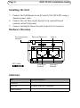
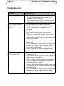
INSTALLATION GUIDE ENGLISH AXIS T8120 Midspan 15 W 1-port Legal Considerations Video and audio surveillance can be prohibited by laws that vary from country to country. Check the laws in your local region before using this product for surveillance purposes. Electromagnetic Compatibility (EMC) USA - Using an unshielded network cable (UTP): This equipment has been tested using an unshielded network cable (UTP) and found to comply with the limits for a Class A digital device, pursuant to part 15 of the FCC Rules. These limits are designed to provide reasonable protection against harmful interference when the equipment is operated in a commercial environment. This equipment generates, uses, and can radiate radio frequency energy and, if not installed and used in accordance with the instruction manual, may cause harmful interference to radio communications. Operation of this equipment in a residential area is likely to cause harmful interference in which case the user will be required to correct the interference at his own expense. Using a shielded network cable (STP): This equipment has also been tested using a shielded network cable (STP) and found to comply with the limits for a Class B digital device, pursuant to part 15 of the FCC Rules. These limits are designed to provide reasonable protection against harmful interference in a residential installation. This equipment generates, uses and can radiate radio frequency energy and, if not installed and used in accordance with the instructions, may cause harmful interference to radio communications. However, there is no guarantee that interference will not occur in a particular installation. If this equipment does cause harmful interference to radio or television reception, which can be determined by turning the equipment off and on, the user is encouraged to try to correct the interference by one or more of the following measures: • Reorient or relocate the receiving antenna. • Increase the separation between the equipment and receiver. • Connect the equipment into an outlet on a circuit • Consult the dealer or an experienced radio/TV technician for help. Europe This digital equipment fulfills the requirements for RF emission according to the Class B limit of EN 55022. This product fulfills the requirements for immunity according to EN 55024 office and commercial environments. Japan - この装置は、クラスB 情報技術装置です。この 装置は、家庭環境で使用することを目 的としていますが 、この装置がラジオやテレビジョン受信機に近接して使 用されると、 受信障害を引き起こすことがあります。 取扱説明書に従って正しい取り扱いをして下さい。 Safety This product complies to EN/IEC 60950-1, Safety of Information Technology Equipment. Korea - ࢇ̛̛Еɼࢽࡈ%̗ࢷળࢶଢ̛̛Ի۰ ࣯Իɼࢽ߾۰ࡈیଜЕʨࡶּࢶࡳԻଜֲֻҘ एࠇ߾۰ࡈیଟܹݡТЬ Canada - This Class B digital apparatus complies with Canadian ICES-003. Australia - This digital equipment fulfills the requirements for RF emission according to the Class B limit of AS/NZS CISPR 22. Trademarks The product described in this guide is a licensed product of PowerDsine. RoHS This product complies with both the European RoHS directive, 2002/95/EC, and the Chinese RoHS regulations, ACPEIP. WEEE Directive The European Union has enacted a Directive 2002/96/EC on Waste Electrical and Electronic Equipment (WEEE Directive). This directive is applicable in the European Union member states. The WEEE marking on this product (see right) or its documentation indicates that the product must not be disposed of together with household waste. To prevent possible harm to human health and/or the environment, the product must be disposed of in an approved and environmentally safe recycling process. For further information on how to dispose of this product correctly, contact the product supplier, or the local authority responsible for waste disposal in your area. Business users should contact the product supplier for information on how to dispose of this product correctly. This product should not be mixed with other commercial waste. For more information, visit www.axis.com/techsup/. Support Should you require any technical assistance, please contact your Axis reseller. If your questions cannot be answered immediately, your reseller will forward your queries through the appropriate channels to ensure a rapid response. If you are connected to the Internet, you can: • download user documentation and firmware updates • find answers to problems in the FAQ database. Search by product, category, phrases. • report problems to Axis support by logging in to your private support area. Contact Information Axis Communications AB Emdalavägen 14 223 69 Lund, Sweden Tel: +46 46 272 18 00 Fax: +46 46 13 61 30 www.axis.com AXIS T8120 Installation Guide Page 3 AXIS T8120 Installation Guide Safety Information • When transporting the Axis product, use the original packaging or equivalent to prevent damage to the product. • Store the Axis product in a dry and ventilated environment. • Do not attempt to repair the product by yourself, contact Axis or your Axis reseller for service matters. • The product should connected to PoE networks only, without routing to the outside plant. • Only qualified personnel can install or remove the product. • The power cord must have regulatory agency approval for the specific country in which is used, (for example UL, CSA, VDE on). • The power cord must be a three-conductor type (two current carrying conductors, one ground conductor) terminated on one end by an IEC 60320 appliance coupler (for connecting to the product) and on the other end by a plug containing a ground (earthing) contact. The power cord must be rated for a minimum of 250 V AC RMS operation, with a minimum rated current capacity of 5 amps (or a minimum wire gauge of 18 AWG (0.75 mm2). • A product installed in Australia requires power cords with a minimum wire gauge of 16 AWG (1.0 mm2). • The products “DATA IN” and “DATA & POWER OUT” ports are shielded RJ45 data sockets. They cannot be used as Plain Old Telephone Service (POTS) telephone sockets. Only RJ45 data connectors can be connected to these sockets. ENGLISH • Avoid exposing the Axis product to vibration, shocks or heavy pressure and do not install the product on unstable brackets, since this could cause damage to the product. Page 4 AXIS T8120 Installation Guide • The AC wall socket outlet must be near the product and easily accessed. AC power can be removed from the product by disconnecting the AC power cord from either the wall socket-outlet or from the products appliance coupler. • The products “DATA IN” and “DATA & POWER OUT” interfaces are qualified as Safety Extra-low Voltage (SELV) circuits according to IEC 60950-1. These interfaces can only be connected to SELV interfaces on other equipment. • The product should only be connected to the IP device with which it was bought. Using the product with other IP devices can cause damage to the IP device. • Follow basic electricity safety measures whenever connecting the device to its power source. • Read the installation instructions before connecting the product to its power source. • A voltage mismatch can cause equipment damage and may pose a fire hazard. If the voltage indicated on the label is different from the power outlet voltage, do not connect the product to this power outlet. • The product can be used only in Restricted Access Locations. AXIS T8120 Installation Guide Page 5 Functions and Features The Power over Ethernet (PoE) Midspan adds 48V DC to unused (nondata) wires (Mode B) in a standard Category 5 Ethernet cable. As a result, the PoE Midspan delivers both data and power to the terminal. The device is designed to meet the IEEE802.3af standard. • Ensure AC power is applied to the PoE Midspan using an operational AC cable with an appropriate ground connection. • Ensure that output Ethernet cable is connected to the Data & Power Out port. • Verify that a power ready Ethernet compatible device is connected. Note: Do not use a cross over cable between the PoE Midspan output port and the load device. Mounting Note the following before mounting the PoE Midspan to a fixed location: • The PoE Midspan may be wall or bench mounted using the rear side holes. • Do not cover the PoE Midspan or block the airflow to the PoE with any foreign objects. Keep the PoE Midspan away from excessive heat and humidity, and keep it free from vibration and dust. • Ensure that the cable length from the Ethernet network source to the terminal does not exceed 100 meters (333 ft). The PoE is not a repeater and does not amplify the Ethernet data signal. • Use a splitter if desired, ensure that the splitter is connected close to the terminal and not on the Midspan. • There is no "on-off" switch, simply plug the PoE Midspan to an AC power source. ENGLISH Preliminary steps Page 6 AXIS T8120 Installation Guide Installing the Unit 1. 2. 3. Connect the PoE Midspan to an AC outlet (100-240 V AC), using a standard power cable. Connect the unit Data In jack (input) to the remote Ethernet network switch Patch panel. Connect the Data & Power Out jack (output) to the terminal. Hardware Overview Port connectivity indicator CAT 5 Cable Data and Power out Output port Terminal Data in Input port Ethernet Indicators LED Yellow On Indicated Behavior Power is on (power is active) Green On A remote terminal is connected Green Blinking Overload state or short-circuit AXIS T8120 Installation Guide Page 7 Specifications Environmental Specifications Mode Temperature Humidity Operating 0 °C to 40 °C (32 °F to 104 °F) 10 to 90% RH (no condensation -20 °C to 70 °C (-4 °F to 158 °F) allowed) Storage Input voltage 100 to 240V AC (50/60 Hz) Input current 0.5 A (maximal) Available Output Power (Maximum) 16.8 W Nominal Output Voltage 48V DC Ethernet Interface Input (Data In): Ethernet 10/100Base-T Output (Data & Power Out): Ethernet 10/100Base-T, plus 48 VDC RJ45 female socket RJ45 female socket, with DC voltage on wire pairs 4-5 and 7-8. ENGLISH Electrical Specifications Page 8 AXIS T8120 Installation Guide Troubleshooting Symptom Corrective Steps Midspan does not power up 1. 2. 3. Verify that an approved power cord is used. Verify that the voltage at the power inlet is between 100 and 240V AC. Remove and re-apply power to the device and check the indicators during power up sequence. A port indicator is not lit 1. The Midspan did not detect a device and and the Midspan does not therefore the port is not enabled. operate 2. Verify that the device is designed for PoE operation 3. Verify that you are using a standard Category 5/ 5e/6, straight-wired cable, with four pairs 4. If there is a connected external power splitter, replace it to verify that it is functioning properly 5. Ensure that the input Ethernet cable is connected to the Data In port 6. Verify that the device is connected to the Data & Power port. 7. Try to reconnect the same device into a different Midspan. If it works, there is probably a faulty port or RJ45 connection. 8. Verify that there is no short over any of the twisted pair cables or over the RJ45 connectors. The end device operates, but 1. Verify that the port indicator on the front panel is there is no data link continuously lit. 2. If an external power splitter is in use, replace it with a known-good splitter. 3. Verify that for this link, you are using standard UTP/FTP Category 5 straight (non-crossover) cabling, with all four pairs. 4. Verify that the Ethernet cable length is less than 100 meters from the Ethernet source to the load/ remote terminal. 5. Try to reconnect the same device into a different Midspan. If it works, there is probably a faulty port or RJ45 connection. Liability Every care has been taken in the preparation of this document. Please inform your local Axis office of any inaccuracies or omissions. Axis Communications AB cannot be held responsible for any technical or typographical errors and reserves the right to make changes to the product and documentation without prior notice. Axis Communications AB makes no warranty of any kind with regard to the material contained within this document, including, but not limited to, the implied warranties of merchantability and fitness for a particular purpose. Axis Communications AB shall not be liable nor responsible for incidental Support or consequential damages in connection with the furnishing, performance or use of this material. This product is only to be used for its intended purpose. Notice Axis’ policy is to improve its products as new technology, components, software, and firmware become available. Axis, therefore, reserves the right to change specifications without prior notice. Installation Guide AXIS T8120 15W Midspan 1-port © Axis Communications AB, 2012-2014 Ver.2.1 Printed: October 2014 Part No. 60330