1
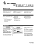
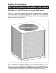
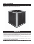
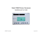
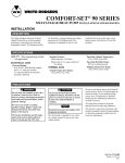
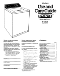
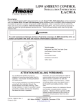
ASC01A
Anti Short-Cycle Control
Heating & Air Conditioning
®
PCK01A
Com fort. Q uality. Trust.
Pressure Control Kits
Installation Instructions
DESCRIPTION
This kit is for use with Amana VCA and RCB remote cooling
units that do not have high or low pressure cutouts or
factory-installed anti short-cycle protector. The Anti ShortCycle Control kit (ASC) prevents short cycling of the compressor. The Pressure Control Kit (PCK) helps protect the
compressor from damage due to abnormally high or low
refrigerant pressures. It also prevents short cycling of the
compressor.
Although it is not mandatory, we recommend that this kit be
installed before the refrigerant lines are connected to the
outdoor unit, and before the line and low voltage wiring is
connected to the outdoor unit.
PCK kits include a high pressure cutout, a low pressure
cutout, and an anti short-cycle control. It also includes tees
for mounting the pressure cutouts on the outdoor unit
service valves. After the tees are installed, a gauge manifold can be attached to them when servicing is necessary.
The ASC kit contains a anti short-cycle protector for use on
units with reciprocating compressors.
BILL OF MATERIAL
PCK01A
2
1
1
1
1
1
1
1
1
1
4
1
ASC01A
Refrigerant Tees, w/valvcores
Low Pressure Cutout, Auto Reset
High Pressure Cutout, Auto Reset
Short Cycle Protector
Yellow-1 Wire
Black-1 Wire
Wire Nut
Wiring Diagram Label
Installation Instructions
Sheet Metal Screw
Teflon Seals
Extension Tube
These kits should only be installed by a qualified, experienced technician.
NOTE: Units with scroll compressors have ASC protectors
installed at the factory.
RECOGNIZE THIS SYMBOL AS A SAFETY PRECAUTION.
ATTENTION INSTALLING PERSONNEL
As a professional installer you have an obligation to
know the product better than the customer. This
includes all safety precautions and related items.
Remember, it is your responsibility to install the
product safely and to know it well enough to be able
to instruct a customer in its safe use.
Prior to actual installation, thoroughly familiarize
yourself with this Instruction Manual. Pay special
attention to all safety warnings. Often during
installation or repair it is possible to place yourself
in a position which is more hazardous than when
the unit is in operation.
Safety is a matter of common sense...a matter of
thinking before acting. Most dealers have a list of
specific good safety practices...follow them.
May 2001
The precautions listed in this Installation Manual
are intended as supplemental to existing practices.
However, if there is a direct conflict between existing
practices and the content of this manual, the
precautions listed here take precedence.
Amana
1810 Wilson Parkway • Fayetteville, TN 37334
10664122
COMPONENT INSTALLATION
PRESSURE CUTOUT INSTALLATION
Anti
Anti Short-Cycle
Control
Control
NOTE: The high and low pressure cutouts on the PCK reset
automatically. All wiring to the pressure cutouts and the anti
short-cycle control must be 24 volt.
The pressure cutouts are installed outside the unit casing.
They are weatherproof but not tamper-proof. Please inform the building owner before installing that tampering
with the pressure cutouts can cause refrigerant leakage
and equipment damage.
Low
Low Pressure
Cutout Wire
High Pressure
Pressur
Cutout Wire
WARNING
To avoid the risk of electrical shock, injury,
or death, disconnect the electrical, power
before installing this kit.
WARNING
To avoid possible injury from refrigerant,
wear gloves and goggles while installing
this kit.
Figure 2
1. Remove and save the caps from the service valves
Schraeder fittings.
High Pressure
Cutout
7. If the service valves have never been opened, proceed
to Anti Short-Cycle Control Installation. If the valves
have been opened, do not run the unit, but perform a
preliminary leak check instead on the tees and pressure switches. If a leak is found, tighten the connection
slightly and recheck. Repeat until leaks are eliminated.
Low Pressure
Cutout
ANTI SHORT-CYCLE CONTROL INSTALLATION
Refrigerant
Tees
Figure 1
2. Install the PCK refrigerant tees onto the Schraeder
fittings (Figure 1). Torque to 10 ft/lbs to avoid refrigerant leaks.
3. Place a Teflon seal in the fitting for the high pressure
(blue wire) cutout. Install this cutout on the liquid line
tee. The liquid line is the smaller of the two lines.
Torque to 10 ft/lbs to avoid refrigerant leaks.
4. Place a teflon seal in the fitting for the low pressure
(yellow wire) cutout. Install this cutout on the suction
line tee. The suction line is the larger of the two lines.
Torque to 10 ft/lbs to avoid refrigerant leaks.
5. Reinstall the caps on the ends of the refrigerant tees.
Finger-tighten.
6. Insert the blue and yellow wires from the pressure
cutouts into the low voltage entrance.
Figure 3
1. Remove and save the control box cover from the unit.
Save the screws which held it in place.
2. In the extreme upper right corner of the control box is
a filler screw. Remove and discard.
3. Mount the anti-short cycle control “upside down” in the
filler hole (Figure 2). Ensure the control terminals are
at the bottom. Secure the control using the large screw
supplied in the kit.
2
WIRING
WIRING
WIRING
PCK01A WIRING
ASC01A WIRING
ASC
PROTECTOR
Y1 R1
Y2 R2
HIGH PRESSURE
CUTOUT
WIRE NUT
BLUE
SHORT CYCLE
PROTECTOR
Y1 R1
Y2 R2
E
BLU
YELL
OW
YL-1
YELLOW 1
LOW PRESSURE
CUTOUT
T2 T1
CONTACTOR
L2 L1
CONTACTOR
T2 T1
YELLOW
BL A
CK-1
Y
BLACK 1
THERMOSTAT
WIRE
THERMOSTAT
WIRE
L2 L1
C
FACTORY INSTALLED
BLACK-1
BLACK 1
Figure 4
UNIT
TERMINAL
BOARD
Figure 5
1. Remove the factory-installed YL-1 low voltage wire
attached to the coil of the compressor contactor and
thermostat wire connection. Discard.
2. Connect the yellow low pressure cutout wire with the
flag terminal to the field-supplied thermostat wire coming from “Y” indoors. Cut and strip if necessary.
Connect the other yellow low pressure cutout wire to
the stripped end of the blue high pressure cutout wire.
Wire nut the ends and crimp (see Figure 4).
3. Attach the flagged end of the blue high pressure cutout
wire to terminal “R1” on the ASC control.
4. Attach one end of the Black-1 wire provided with the
PCK kit to terminal “R2” on the ASC control. Attach the
other end to the field-supplied thermostat wire coming
from terminal “C” indoors and the factory-installed
Black-1 wire coming from the coil of the compressor
contactor.
5. Attach one end of the YL-1 wire provided with the kit to
terminal “Y1” on the ASC control. Attach the other end
of this wire to the coil of the compressor contactor.
6. Using the wiring diagram (10799001) included in the kit
as a guide, inspect all wiring to ensure that all connections are tight and no errors have been made.
7. Remove the backing from the wiring diagram. Without
covering the unit wiring diagram, attach the PCK wiring
diagram on the inside of the control box cover.
1. The Black-1 wire provided with the kit includes a
piggyback terminal. Attach this end to “R2” on the short
cycle control.
2. Disconnect the BK-1 wire that runs from unit contactor
to low voltage connection and reconnect this end to the
piggyback terminal on the “R2” terminal of the short
cycle control.
3. Connect the other end of the BK-1 wire supplied with
the kit to the unit contactor (same terminal disconnected in step 2 above).
4. Disconnect YL-1 wire at the contactor end and reconnect it to the “R1” terminal on the anti short-cycle
control.
5. Connect one end of the YL-1 wire supplied with the kit
to the Y1 terminal on the short cycle control and the
other end to the unit contactor coil terminal vacated in
step 4.
6. Use the anti short-cycle control wiring label, 11036301,
which is included in the ASC kit, as a guide. Inspect all
wiring carefully to ensure that all connections are tight
and no errors have been made.
7. Remove the backing from the anti short-cycle control
label. Without covering the unit wiring diagram, attach
the label on the inside of the control box cover.
3
WRAP-UP
WRAP-UP
1. Replace the cover on the control box.
2. To complete the outdoor unit installation, refer to the outdoor unit
Installation Manual.
3. When the system installation is complete and the outdoor temperature
is 50°F or higher, run the system to confirm proper operation:
— If any sparking, unusual noises, or unusual odors are noticed,
immediately disconnect the electrical power, then recheck wiring and
components.
— Upon the initial call for cooling, the compressor and outdoor fan
should start. The high and low pressure switches should both be
closed.
— End the call for cooling, and then immediately begin another call for
cooling. Assuming that no indoor fan time delay relay is present, the
indoor fan should restart immediately, but the compressor and
outdoor fan should not restart for about 3 minutes.
— To avoid possible equipment damage, do not adjust airflow or
refrigerant charge in an attempt to cause the pressure switches to
open. The high pressure switch opens at about 400 psi, and closes
at about 300 psi. The PCK01A low pressure switch opens at about
35 PSI, and closes at about 85 PSI. A properly operating cooling
system will not experience pressure extremes enough to cause
these pressure switches to open.
4. While the system is operating, perform a final refrigerant leak check on
the tees and pressure switches. If a leak is found, tighten the joint
slightly and retest. Repeat until all leaks are eliminated.
4