1
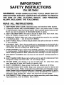
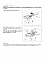
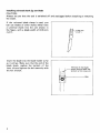
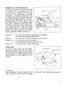
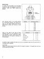
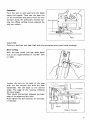
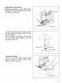
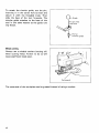
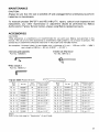
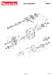
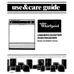
Electronic Jig Saw
MODEL 4303C
INSTRUCTION MANUAL
SPECIFICATIONS
Max. cutting capacities
Length of
stroke
26 mm
(1")
Wood
1
'Omm
(2.318")
Strokes
I I!$:
Overall
length
per minute
Steel
1
1,000 - 3,000
I
2
19mm
(8-518")
Manufacturer reserves the right to change specifications w i t h o u t notice.
Note: Specifications may differ from country t o country.
WARNING: For your personal safety, READ and UNDERSTAND before using.
SAVE THESE INSTRUCTIONS FOR FUTURE REFERENCE.
I
1
weight
Net
2.5 kg
(5.5 Ibs)
IMPORTANT
SAFETY INSTRUCTIONS
(For All Tools)
WARNING: WHEN USING ELECTRIC TOOLS, BASIC SAFETY
PRECAUTIONS SHOULD ALWAYS BE FOLLOWED TO REDUCE
THE RISK OF FIRE, ELECTRIC SHOCK, AND PERSONAL
INJURY, INCLUDING THE FOLLOWING:
READ ALL INSTRUCTIONS.
1. KEEP WORK AREA CLEAN. Cluttered areas and benches invite injuries.
2. CONSIDER WORK AREA ENVIRONMENT. Don't use power tools in damp
or wet locations. Keep work area well lit. Don't expose power tools t o rain.
Don't use tool in presence of flammable liquids or gases.
3. KEEP CHILDREN AWAY. All visitors should be kept away from work area.
Don't let visitors contact tool or extension cord.
4.STORE IDLE TOOLS. When not in use, tools should be stored in dry, and high
or locked-up place - out of reach of children.
5 . DON'T FORCE TOOL. It will do the job better and safer at the rate for which
it was intended.
6. USE RIGHT TOOL. Don't force small tool or attachment t o do the job of a
heavy-duty tool. Don't use tool for purpose not intended; for example, don't
use circular saw for cutting tree limbs or logs.
7 . DRESS PROPERLY. Don't wear loose clothing or jewelry. They can be caught
in moving parts. Rubber gloves and non-skid footwear are recommended
when working outdoors. Wear protective hair covering t o contain long hair.
8. USE SAFETY GLASSES. Also use face or dust mask i f cutting operation is
dusty.
9. DON'T ABUSE CORD. Never carry tool by cord or yank it t o disconnect from
receptacle. Keep cord from heat, oil, and sharp edges.
10. SECURE WORK. Use clamps or a vise t o hold work. It's safer than using
your hand and it frees both hands t o operate tool.
11. DON'T OVERREACH. Keep proper footing and balance at all times.
12. MAINTAIN TOOLS WITH CARE. Keep tools sharp and clean for better and
safer performance. Follow instructions for lubricating and changing accessories. Inspect tool cords periodically and if damaged, have repaired by authorized service facility. Inspect extension cords periodically and replace if
damaged. Keep handles dry, clean, and free from oil and grease.
13. DISCONNECT TOOLS. When not in use, before servicing, and when changing accessories, such as blades, bits, cutters.
2
14. REMOVE ADJUSTING KEYS AND WRENCHES. Form habit of checking t o
see that keys and adjusting wrenches are removed from tool before turning
it on.
15. AVOID UNINTENTIONAL STARTING. Don’t carry tool with finger on switch.
Be sure s w i t c h is OFF when plugging in.
16. EXTENSION CORDS. Make sure your extension cord is in good condition.
When using an extension cord, be sure t o use one heavy enough t o carry
the current your product will draw. A n undersized cord will cause a drop
i n line voltage resulting in loss of power and overheating. Table 1 shows the
correct size t o use depending on cord length and nameplate ampere rating.
If in doubt, use the next heavier gage. The smaller the gage number, the
heavier the cord.
TABLE 1
MINIMUM GAGE
FOR CORD SETS
Total Length of Cord in Feet
0 - 25
26
- 50
Ampere Rating
More
Not More
Than
Than
0
6
10
12
-
6
10
12
16
51 - 100
101 - 150
AWG
18
18
16
14
16
16
16
12
:
I
14
12
14
12
Not Recommended
3
VOLTAGE WARNING: Before connecting the tool to a power source (receptacle,
outlet, etc.) be sure the voltage supplied is the same as that specified on the
nameplate of the tool. A power source with voltage greater than that specified
for the tool can result in SERIOUS INJURY to the user - as well as damage to
the tool. If in doubt, DO NOT PLUG IN THE TOOL. Using a power source with
voltage less than .the nameplate rating is harmful to the motor.
ADDITIONAL SAFETY RULES
1. Avoid cutting nails. Inspect for and remove all nails from the workpiece before operation.
2. Don't cut hollow pipe.
3. Do not cut oversize workpiece.
4. Check for the proper clearance beneath the workpiece before cutting so that
the blade will not strike the floor, workbench, etc.
5. Hold the tool firmly.
6. Make sure the blade is not contacting the workpiece before the switch is
turned on.
7. Keep hands away from moving parts.
8. When cutting through walls, floors or wherever "live" electrical wires may
be encountered, DO NOT TOUCH ANY METAL PARTS OF THE TOOL!
Hold the tool only by the insulated grasping surfaces to prevent electric shock
if you cut through a "live" wire.
9. Do not leave the tool running. Operate the tool only when hand-held.
IO. Always switch off and wait for the blade to come to a complete stop before
removing the blade from the workpiece.
11. Do not touch the blade or the workpiece immediately after operation; they
may be extremely hot and could burn your skin.
SAVE THESE INSTRUCTIONS.
4
Installing Makita jig saw blade
CAUTION :
Always be sure that the tool is switched off and unplugged before installing or removing
the blade.
Use the hex wrench to loosen the bolt.
With the blade teeth facing forward, insert
the blade into the blade holder as far as
it will go.
Make sure that the back edge of the blade
fits into the roller and tighten the bolt
securely with the hex wrench.
I *
Jig saw blade
CAUTION :
Use a lubricant or cutting oil between the blade and roller when cutting iron or composition board, etc. Failure to do so will shorten the service life of your blade and roller.
5
Installing universal shank jig saw blade
CAUTION :
Always be sure that the tool is switched off and unplugged before installing or removing
the blade.
If the universal blade clamp i s used, you
can use blades of other makes which have
a universal shank like the one shown in
the figure, with a blade width of 6.35 mm
(1/4").
Insert the blade into the blade holder as far
as it will go. Make sure that the end of the
blade shank reaches the bottom of the
inner s l i t and tighten the bolt securely with
The end of the blade
shank should reach the
bottom of the inner slit
the hex wrench.
il
6
Straight line or orbital cutting action
Conventional jig saws cut with a straight
line action, that is, the blade moves only
up and down in a straight line. Your saw
also cuts in this manner but, for softer
workpieces, an orbital cutting action can
be selected. Soft workpieces like wood and
plastic permit deep penetration of individual saw teeth. The orbital action thrusts
the blade forward on the cutting stroke
and greatly increases cutting speed over
conventional jig saws. Harder workpieces
like metal should be cut using the straight
line cutting action or a very low orbital
setting. To select straight line or orbital
cutting, adjust the number on the saw.
I
\
Lever
Position 0 - For cutting in mild steel, stainless steel and plastics.
For clean cuts in wood and plywood.
Position I - For cutting in mild steel, aluminum and hard wood.
Position I1
-
Position I11 -
For cutting in wood and plywood.
For fast cutting in aluminum and mild steel.
For fast cutting in wood and plywood.
Switch action
To start the tool, simply pull the trigger.
Release the trigger to stop. For continuous
operation, pull the trigger and then push in
the lock button. To stop the tool from the
locked position, pull the trigger fully, then
release it.
Lock button
/
Switch triqqer
CAUTION :
Before plugging in the tool, always check to see that the switch trigger actuates properly
and returns to the "OFF" position released.
Speed change
To adjust the tool speed, turn the speed
change dial. The tool speed can be adjusted
between 1,000 and 3,000 strokes per
minute.
The reference table on the right denotes
the relationship between the number settings on the speed change dial and the
approximate strokes per minute a t that
setting.
Number
1,000
2
1,200
I
1,700
1
I
3
1
1
4
2,200
1
1
5
2,700
I
3,000
I
6
Refer to the table on the right to select
suggested speed for the workpiece to be
cut. However, proper speed may differ
depending upon the type or thickness of
the workpiece.
Strokes per minute
1
Wor kpiece
Wood
M i l d steel
Stainless steel
Aluminum
Plastics
I
I
I
Number
5-6
3-6
3-4
2-3
1-4
In general, higher speeds will allow you to cut a workpiece faster but the service life of
the blade will be reduced.
CAUTION :
Adjust the speed change dial only within the range of numbers 1 through 6. Do not force
the dial beyond this range.
8
Operation
Turn the tool on and wait until the blade
attains full speed. Then rest the base flat
on the workpiece and gently move the tool
forward along the previously marked cutting line. When cutting curves, advance the
tool very slowly.
I
.
I
CAUTION :
Failure to hold the tool base flush with the workpiece may cause blade breakage.
Bevel cutting
With the base tilted, you can make bevel
cuts a t any angle between 0" and 45" (left
or right).
Loosen the bolt on the back of the base
with the hex wrench and slide the base
backwards. Tilt the base to the desired
angle. The edge of the housing indicates
the bevel angle.
Then check the contact between the back
edge of the blade and the roller.
Now tighten the bolt securely on the back
of the base.
Edge of housing
9
Front flush cuts
Loosen the bolt on the back of the base
with the hex wrench, then slide the base
backwards. Check the contact between the
back edge of the blade and the roller, then
secure the bolt.
Plunge cutting
Starting a cut a t other than the edge of the
workpiece without first drilling a starting
hole requires a "plunge cut". This can be
accomplished by tipping the tool forward
until the front end of the base rests against
the workpiece. Switch the tool on and
lower the back end of the tool slowly,
gradually allowing the blade to saw through
the workpiece until the base i s able to s i t
flat on the workpiece. You may then proceed forward with the cut in a normal
manner.
If using a drill for a starting hole, bore a
hole over 12 mm (1/2") in diameter. Then
insert the blade in it and proceed.
Finishing edges
To trim edges or make dimensional adjustments run the blade lightly along the cut
edges.
For smoother cutting of plywood or other
workpieces with easily splintered surfaces,
transparent tape may be used over your
cutting line.
10
I
I
Using guide rule (Rip fence)
When cutting widths of under 150 m m (6")
repeatedly, use of the guide rule will assure
fast, clean, straight cuts.
~
To attach the guide rule (rip fence), secure
the rule holder to the base with the screw
(do not tighten).
Insert the guide rule between the base and
the rule holder. Now tighten the screw
with the hex wrench.
I
Rule holder
Guide rule
Screw
Hex wrench
Using circular guide
Use of the circular guide insures clean,
smooth cutting of circles (radius; under
200 m m ; 7-7/8")and arcs.
I
Circular guide
11
To attach the circular guide, use the pin,
inserting it in the center hole (arrow) and
secure it with the threaded knob. Then
slide the base of the tool forwards. The
circular guide attaches to the base of the
tool in the same manner as the guide rule
(rip fence).
0I
Knob
F i t pin into
this hole
b
Pin for
circular guide
Metal cutting
Always use a suitable coolant (cutting oil)
when cutting metal. Failure to do so will
cause significant blade wear.
I
Cutting oil
The underside of the workpiece can be greased instead of using a coolant.
12
MAINTENANCE
CAUTION:
Always be sure that the tool is switched off and unplugged before attempting to perform
inspection or maintenance.
To maintain product SAFETY and RELIABILITY, repairs, carbon brush inspection and
replacement, any other maintenance or adjustment should be performed by Makita
Authorized or Factory Service Centers, always using Makita replacement parts.
ACC ESSOR I ES
CAUTION:
These accessories o r attachments are recommended f o r use w i t h y o u r Makita tool specified in this
manual. The use of any other accessories o r attachments m i g h t present a risk o f injury to persons. The
accessories o r attachments should be used o n l y in the proper and intended manner.
A n exception: Universal shank jig saw blades w i t h a thickness of 1 mm - 1.25mm (1/32"- 3/64")
and a length o f 58 mm - 82 mm (2-9/32"
- 3-7/32").
0
Circular guide assembly
Part No. 123030-5
Hex wrench 3
Part No. 783201-2
s Jig saw blade (Packed 5 each)
0
Guide rule (Rip fence)
Part No. 1641 13-2
-
(Note)
Refer to the next page for "Application" of each blade.
13
Jig saw blade
Application
No. 51
I
Plastics
Aluminum
Mild steel
1.5 - 3 mm thick
11/16’ - 1/8”)
1 - 6 mm thick
13/64” - 1/4‘l
3 mm thick
13/64’’ - 1/8”l
4
-
30 mm thick
I
For fast cutting.
4 - 30 mm thick
15/32’’ - 1-1/8“)
For fast finish work.
No.
6-13
No.
6-14
I
I
8-15
No.
6-16
-
I
For fast finish work.
I
I
I
I
H
I
I
5 - 60 mm thick
(13/64“ - 2-3/8”)
I
4 - 60 mm thick
15/32” - 2-3/8‘)
4 - 60 mm thick
15/32” - 2-3/8”1
2 - 30 mm thick
15/64‘’ - 1-1/8”1
2 - 30 mm thick
15/64‘’ - 1-1/8”)
U
-
l-l/8”)
5 - 60 mm thick
l13/64“ - 2-3/8”)
3 - 30 mm thick
11/8‘ - 1-1/8”)
9
Y q z15/64”
F K
- 1-1/8”)
x r
No.
For fast finish work.
2-3/8”)
( 13/64” - 2-3/8“)
6-19
3 - 30 mm thick
11/8“ - l - l / 8 ” )
No.
No.
8-27
3 - 30 mm thick
11/8” - 1-1/8”)
H
3 - 55 mm thick
(1/8” - 2-1/8”)
I
I
-
3 - 10 mm thick
1118‘’ - 318”)
I
I
I
Cuts on down stroke.
Splinter-free on finish side.
I
For finish work,
especially in plastics
1 - 6 mm thick
(3164‘’ - 114“)
1 - 3 mm thick
3 - 10 mm thick
(1/8” - 3/8”l
3 - 6 mm thick
( 1 /8” - 1/4”)
Also ideal for cutting
stainless steel.
0.5 - 2 mm thick
11/64” - 5/64”)
Also ideal for cutting
stainless steel.
0.5
- 3 mm thick
11/64“ - 1/8”)
13/64”
I
-
1/8”)
- 10 mm thick
11/8” - 3/8”)
3 - 55 mm thick
11/8” - 2-1/8”)
3 - 55 mm thick
(1/8“ - 2-1/8”)
Also ideal for cutting
stainless steel.
3 - 30 mm thick
11/8” - l - l / 8 ” )
3
3 - 30 mm thick
1118’’ - 1-118”)
3 - 10 mm thick
11/8” - 3/8”)
Ideal for scroll cutting
1 - 3 mm thick
13/64” - 118”)
Ideal for scroll cutting.
H
Ideal for cutting
thick materials.
H
-
1.5 - 3 mm thick
11/16’’ - 118”)
NOTE:
”H” s t a n d s for h a r d m a t e r i a l s
”S” s t a n d s for s o f t m a t e r i a l s
14
For fast cutting.
Ideal for scroll cutting
- 3 mm thick
13/64’ - 118”)
H
I
1
-
2 - 30 mm thick
15/64” - 1-1/8”)
1
No.
Ideal for cutting
thin materials.
Ideal for scroll cutting.
3 - 6 mm thick
(118’’ - 1/4”)
6-26
I
1.5 - 3 mm thick
11/16’’ - 1/8”)
3 - 55 mm thick
For roughing-in work
Ideal for cutting
thin materials.
H
I
-
5 - 60 mm thick
(13/64” - 2-3/8”)
3 - 55 mm thick
11/8” - 2-1/8”)
6-22
For fast finish work,
especially in plywood
-
3 - 30 mm thick
l1/8” - 1-1/8”1
11/8”
I
-
S
113/64”
Feature
Also ideal for cutting
stainless steel.
4 - 60 mm thick
15/32’’ - 2-3/8”)
3 - 60 mm thick
ll/8” - 2-318”)
No.
-
H
4 - 60 mm thick
8-11
1
U
1
-
6 mm thick
13/64”
-
114”)
May-19--'94
US
ELECTRONIC JIG SAW
Model 4303C
Note: The switch and other part configurations
may differ from country to country.
15
MODEL 4303C
May-19-'94
ZDDESCRIPTION
E=
ITEM
NO
NO
USED
US
IKSCRIPTION
MA1
~
1
1
41
2
1
42
3
1
1
43
4
5
6
1
1
4
7
8
9
0
1
1
11
2
3
44
45
46
47
48
49
50
51
52
14
18
1
53
51
3
55
19
1
56
20
1
1
1
21
22
23
24
1
1
1
1
25
26
2,
28
29
57
58
59
60
61
62
63
64
55
66
30
31
32
33
67
1
1
66
Pan Head Screw MSr2S lWllh Warherl
Hourlng se, lWlth ,,em 2,
Rvbbsr P," 4
Retalnlng Ring s 6
e" 4
Relamel
Roller
sponge Sheet
69
D"3, mate
stop Ring E
70
P," 5
34
72
Cord
35
75
75
79
80
Carbon Brush
36
31
38
3
BWSh Holder
ControllFr
Proteclo,
39
40
-
MAKITA LIMITEDONE YEAR WARRANTY
Warranty Policy
I very Uakttd tool is thoroughly mspected and tasted before leaving the factory
I t IS warranted to
bc free of detects trom workmanship and matenalr tor the penod of ON1 Y I AR from the date ot
ongnal purthax Shuuld any trouble develop dunng this une-year penod. return the (OMPLFTI
tool. freight prepaid. to one of Maktta's F d ~ t o r yor Authorized S ~ N I CCenter,
C
If inspection shows
the trouble IS Laused by defective uorkmanship or matenal. hlakita wdl repair (ur dl our option.
replace) without charge
.
This Warranty does not apply where:
repairs have been made or attempted by others:
repairs are required because of normal wear and tear:
The tool has been abused, misused or improperly maintained;
alterations have been made to the tool.
IN NO EVENT SHALL MAKITA BE LIABLE FOR ANY INDIRECT, INCIDENTAL OR CONSEQUENTIAL DAMAGES FROM THE SALE OR USE O F THE PRODUCT. THIS DISCLAIMER
APPLIES BOTH DURING AND AFTER THE TERM O F THIS WARRANTY.
MAKITA DISCLAIMS LIABILITY FOR ANY IMPLIED WARRANTIES, INCLUDING IMPLIED
WARRANTIES O F "MERCHANTABILITY" AND "FITNESS FOR A SPECIFIC PURPOSE,"
AFTER THE ONE-YEAR TERM OF THIS WARRANTY.
This Warranty gives you specific legal rights, and you may also have other rights which vary from
state to state. Some states do not allow the exclusion or Limitation of incidental or consequential
damages, so the above limitation or exclusion may not apply to you, Some states do not allow
limitation on how long an implied warranty lasts, so the above limitation may not apply to you.
Makita Corporation
3-11-8, Sumiyoshi-cho,
Anjo, Aichi 446 Japan
883885 - 069
PRINTED IN JAPAN
1994 - 6 - N