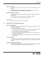
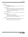
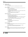
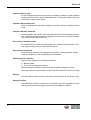
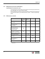
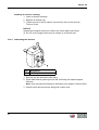
1
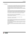
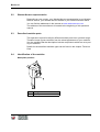
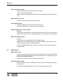
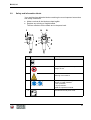
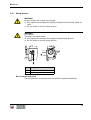
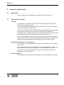
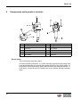
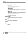
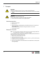
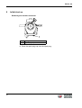
Operator's manual Gasoline demolition hammer BH 23, 24 12.2009 0109963en / 005 Manufacturer Wacker Neuson SE Preußenstraße 41 80809 München www.wackerneuson.com Tel.: +49-(0)89-354 02-0 Fax: +49-(0)89-354 02-390 Translation of the original operator’s manual in German Contents BH 23, 24 1 Foreword .................................................................................................................... 5 2 Introduction ............................................................................................................... 6 2.1 Means of representation for this operator's manual ........................................... 6 2.2 Wacker Neuson representative .......................................................................... 7 2.3 Described machine parts.................................................................................... 7 2.4 Identification of the machine............................................................................... 7 3 Safety ......................................................................................................................... 9 3.1 Principle.............................................................................................................. 9 3.2 Qualification of the operating personnel ........................................................... 12 3.3 Protective gear ................................................................................................. 13 3.4 Transport .......................................................................................................... 14 3.5 Operating safety ............................................................................................... 15 3.6 Safety during the operation of hand machines ................................................. 17 3.7 Safety during the operation of combustion engines ......................................... 17 3.8 Maintenance ..................................................................................................... 19 3.9 Safety and information labels ........................................................................... 21 3.10 Safety devices .................................................................................................. 23 4 Scope of delivery .................................................................................................... 24 5 Structure and function ........................................................................................... 25 5.1 Application ........................................................................................................ 25 5.2 Functional description....................................................................................... 25 6 Components and operator's controls ................................................................... 26 7 Transport ................................................................................................................. 28 8 Initial start up .......................................................................................................... 30 9 Use and operation ................................................................................................... 31 9.1 Prior to starting the machine............................................................................. 31 9.2 Adjusting the machine ...................................................................................... 32 9.3 Changing tools.................................................................................................. 33 9.4 Starting up ........................................................................................................ 34 9.4.1 Starting the engine ............................................................................... 35 9.5 Operating the machine ..................................................................................... 37 9.6 Decommissioning ............................................................................................. 38 10 Maintenance ............................................................................................................ 39 10.1 Maintenance personnel qualifications .............................................................. 40 3 BH 23, 24 10.2 Maintenance schedule ..................................................................................... 10.3 Maintenance work ............................................................................................ 10.3.1 Cleaning machine................................................................................. 10.3.2 Topping up with fuel ............................................................................. 10.3.3 Checking/cleaning air cleaner .............................................................. 10.3.4 Lubricating the machine ....................................................................... 10.3.5 Checking/cleaning/replacing spark plug ............................................... 10.3.6 Checking the tool holder for wear......................................................... 40 41 41 42 43 44 45 46 11 Malfunctions ............................................................................................................ 47 12 Storage ..................................................................................................................... 48 13 Disposal ................................................................................................................... 49 13.1 Disposal of the machine ................................................................................... 49 14 Accessories ............................................................................................................. 50 14.1 Truck ................................................................................................................ 50 15 Technical data ......................................................................................................... 52 15.1 BH 23 ............................................................................................................... 52 15.2 BH 24 ............................................................................................................... 54 EC Declaration of Conformity ................................................................................ 57 4 1 Foreword 1 Foreword This operator's manual contains information and procedures for the safe operation and maintenance of your Wacker Neuson machine. In the interest of your own safety and to prevent accidents, you should carefully read through the safety information, familiarize yourself with it and observe it at all times. This operator's manual is not a manual for extensive maintenance and repair work. Such work should be carried out by Wacker Neuson service or authorized specialists. The safety of the operator was one of the most important aspects taken into consideration when this machine was designed. Nevertheless, improper use or incorrect maintenance can pose a risk. Please operate and maintain your Wacker Neuson machine in accordance with the instructions in this operator's manual. Your reward will be troublefree operation and a high degree of availability. Defective machine parts must be replaced immediately! Please contact your Wacker Neuson representative if you have any questions concerning operation or maintenance. All rights reserved, especially reproduction and distribution rights. Copyright 2009 Wacker Neuson SE No part of this publication may be reproduced in any form or by any means, electronic or mechanical, including photocopying, without the expressed written permission of Wacker Neuson. Any type of reproduction, distribution or storage on data media of any type and form not authorized by Wacker Neuson represents an infringement of copyright and will be prosecuted. We expressly reserve the right to make technical modifications – even without special notice – which aim at further improving our machines or their safety standards. 5 BH 23, 24 2 2.1 Introduction Means of representation for this operator's manual Warning symbols This operator's manual contains safety information of the categories: DANGER, WARNING, CAUTION, NOTICE. They should be followed to prevent danger to life and limb of the operator or damage to equipment and exclude improper service. DANGER This warning notice indicates immediate hazards that result in serious injury or even death. f Danger can be avoided by the following the actions mentioned. WARNING This warning notice indicates possible hazards that can result in serious injury or even death. f Danger can be avoided by the following the actions mentioned. CAUTION This warning notice indicates possible hazards that can result in minor injury. f Danger can be avoided by the following the actions mentioned. NOTICE This warning notice indicates possible hazards that can result in material damage. f Danger can be avoided by the following the actions mentioned. Notes Note: Complementary information will be displayed here. Instructions f This symbol indicates there is something for you to do. 1. Numbered instructions indicate that you have to carry out something in a defined sequence. 6 This symbol is used for lists. BH 23, 24 2.2 Wacker Neuson representative Depending on your country, your Wacker Neuson representative is your Wacker Neuson service, your Wacker Neuson affiliate or your Wacker Neuson dealer. You can find the addresses in the Internet at www.wackerneuson.com. The address of the manufacturer is located at the beginning of this operator's manual. 2.3 Described machine parts This operator's manual is valid for different machine parts from a product range. Therefore some figures can differ from the actual appearance of your machine. It is also possible that the descriptions include components which are not a part of your machine. Details for the described machine types can be found in the chapter Technical Data. 2.4 Identification of the machine Nameplate position Item 1 Designation Nameplate 7 BH 23, 24 Nameplate data The nameplate lists information that uniquely identifies your machine. This information is needed to order spare parts and when requesting additional technical information. f Enter the information of your machine into the following table: Item 8 Designation 1 Group and type 2 Construction year 3 Machine no. 4 Version no. 5 Item no. Your information BH 23, 24 3 3.1 Safety Principle State of the art This machine has been constructed with state-of-the-art technology according to the recognized rules of safety. Nevertheless, when used improperly, dangers to the life and limb of the operator or to third persons or damage to the machine or other materials cannot be excluded. Proper use The machine must only be used for the following purposes: Breaking off concrete and asphalt and soil that is full of boulders. Breaking off concrete, masonry and other construction materials, untouched and frozen ground. Scarifying roads and concrete, asphalt, tar and wooden and stone paving. Cutting clay, loam, peat and salts. Breaking up compacted soils. Ramming in posts, probes and grounding rods. To tamp sleepers in track construction (only EH 22). The machine may only be used with tools that are intended for use with the machine and the material being worked on. The machine may not be used for the following purposes: Working on hazardous materials such as asbestos. Its proper use also includes the observance of all instructions contained in this operator's manual as well as complying with the required service and maintenance instructions. Any other use is regarded as improper. Any damage resulting from improper use will void the warranty and the liability on behalf of the manufacturer. The operator assumes full responsibility. 9 BH 23, 24 Structural modifications Never attempt to modify the machine without the written permission of the manufacturer. To do so will endanger your safety and the safety of other people! In addition, this will void the warranty and the liability on behalf of the manufacturer. Especially the following are cases of structural modifications: Opening the machine and the permanent removal of components from Wacker Neuson. Installing new components which are not from Wacker Neuson and not equivalent to the original parts in design and quality. Installation of accessories which are not from Wacker Neuson. It is no problem to install spare parts from Wacker Neuson. It is no problem to install accessories that are available in the Wacker Neuson product range of your machine. Please refer to the installation regulations in this operator's manual. Do not drill into the housing, e.g. to install signs. Water could penetrate the housing and damage the machine. Requirements for operation The ability to operate the machine safely requires: Proper transport, storage and setup. Careful operation. Careful service and maintenance. Operation Operate the machine only as intended and only when in proper working condition. Operate the machine in a safety-conscious manner with all safety devices attached and enabled. Do not modify or disable any safety devices. Before starting operation, check that all control and safety devices are functioning properly. Never operate the machine in a potentially explosive environment. Maintenance Regular maintenance is required in order for the machine to operate properly and reliably over time. Failure to perform adequate maintenance reduces the safety of the machine. 10 Strictly observe the prescribed maintenance intervals. Do not use the machine if it requires maintenance or repairs. BH 23, 24 Malfunctions If you detect a malfunction, you must shut down and secure the machine immediately. Eliminate the malfunctions that impair safety immediately! Have damaged or defective components replaced immediately! For further information, refer to chapter Malfunctions. Spare parts, accessories Use only spare parts from Wacker Neuson or such that are equivalent to the original parts in design and quality. Only use accessories from Wacker Neuson. Non-compliance will exempt the manufacturer from all liability. Exclusion of liability Wacker Neuson will refuse to accept liability for injuries to persons or for damage to materials in the following cases: Structural modifications. Improper use. Failure to comply with this operator's manual. Improper handling. Using of spare parts which are not from Wacker Neuson and not equivalent to the original parts in design and quality. Using of accessories which are not from Wacker Neuson. Operator's manual Always keep the operator's manual near the machine or near the worksite for quick reference. If you have misplaced the operator's manual or require an additional copy, contact your Wacker Neuson representative or download the operator's manual from the Internet (www.wackerneuson.com). Always hand over this operator's manual to other operators or to the future owner of the machine. Country-specific regulations Observe the country-specific regulations, standards and guidelines in reference to accident prevention and environmental safety, for example those pertaining to hazardous materials and wearing protective gear. Complement the operator's manual with additional instructions taking into account the operational, regulatory, national or generally applicable safety guidelines. 11 BH 23, 24 Operator's controls Always keep the operator's controls of the machine dry, clean and free of oil or grease. Operating elements such as ON/OFF switch, gas handles etc. may not be locked, manipulated or changed without authorization. Checking for signs of damage Inspect the machine when it is switched off for any signs of damage at least once per work shift. Do not operate the machine if there is visible damage or defects. Have any damage or defects eliminated immediately. Supervision Never leave the machine running unattended! 3.2 Qualification of the operating personnel Operator qualifications Only trained personnel are permitted to start and operate the machine. The following rules also apply: You are physically and mentally fit. You have received instruction on how to independently operate the machine. You have received instruction in the proper use of the machine. You are familiar with required safety devices. You are authorized to start machines and systems in accordance with the standards governing safety. Your company or the operator has assigned you to work independently with this machine. Incorrect operation Incorrect operation or misuse by untrained personnel can endanger the health and safety of the operator or third persons and also cause machine and material damage. Operating company responsibilities The operating company must make the operator's manual available to the operator and ensure that the operator has read and understood it. 12 BH 23, 24 Work recommendations Please observe the recommendations below: 3.3 Work only if you are in a good physical condition. Work attentively, particularly as you finish. Do not operate the machine when you are tired. Carry out all work calmly, circumspectly and carefully. Never operate the machine under the influence of alcohol, drugs or medication. This can impair your vision, reactions and your judgment. Work in a manner that does not endanger others. Ensure that no persons or animals are within the danger zone. Protective gear Work clothing Clothing should be appropriate, i.e. should be close-fitting but not restrict your movement. When on construction sites, do not wear long hair loosely, loose clothing or jewelry including rings. These objects can easily get caught or be drawn in by moving machine parts. Only wear clothing made of material that is not easily flammable. Personal protective gear Wear personal protective gear to avoid injuries or health hazards: Non-skid, hard-toed shoes. Work gloves made of durable material. Overalls made of durable material. Hard hat. Ear protection. Face protection. Eye protection. Breathing protection in the case of dusty ambient air. Ear protection This machine generates noise that exceeds the country-specific permissible noise levels (individual rating level). It may therefore be necessary to wear ear protection. You can find the exact value in the chapter Technical Data. When wearing ear protection while working, you must pay attention and exercise caution because your hearing is limited, e.g. in case someone screams or a signal tone sounds. Wacker Neuson recommends that you always wear ear protection. 13 BH 23, 24 3.4 Transport Switching off the machine Before you transport the machine, it must be switched off, and the engine must be given sufficient time to cool down. Emptying the tank Wacker Neuson recommends that the fuel tank be emptied and the carburetor run dry prior to transporting it. Fuel could run out, e.g. if the machine is tilted. Observe the national safety guidelines and the hazardous materials regulations that apply to the respective means of transportation. Transporting the machine Secure the machine on the transport device against tilting, falling or slipping. Lifting the machine A falling machine can cause serious injuries. The machine has no lifting or lashing points. When lifting the machine, secure it in a closed transport container or similar in order to prevent it from toppling, falling or slipping away. Restarting Machines, machine parts, accessories or tools that were detached for transport purposes must be re-mounted and fastened before restarting. Only operate in accordance with the operating instructions. 14 BH 23, 24 3.5 Operating safety Explosible environment Never operate the machine in a potentially explosive environment. Work environment Familiarize yourself with your work environment before you start work. This includes e.g. the following items: Obstacles in the work and traffic area. Load-carrying capacity of the ground. The measures needed to cordon off the construction site from public traffic in particular. The measures needed to secure walls and ceilings. Options available in the event of an accident. Safety in the work area When working with the machine especially pay attention to the following points: Electric lines or pipes in work area. Gas lines or water lines in the work area. Material becoming separated, dropping down or ejected. Make sure that you do not put other persons in danger. Pay maximum attention in the vicinity of drops or slopes. Risk of falling. Maintain a sufficient distance from flammable materials. Checks before starting work Check the following points before beginning work: Condition of tools. Machine settings. Starting the machine Observe the safety information and warning notices located on the machine and in the operator's manual. Never attempt to start a machine that requires maintenance or repairs. Start the machine as described in the operator's manual. Vertical stability Always make sure that you stand firmly when working with the machine. This applies particularly when working on scaffoldings, ladders, uneven or slippery floors etc. 15 BH 23, 24 Caution with hot parts Do not touch any hot parts such as tools, tool holders, mufflers or guide cylinders during operation or for a short period afterwards. These parts can become very hot and can cause severe burns. Caution with movable parts Keep your hands, feet and loose clothing away from moving or rotating machine parts. Caution with toxic materials Some materials may contain toxic chemicals which are released during demolition. Therefore personal protective equipment must be worn to prevent inhalation of and skin contact with work dust. Do not direct towards people Do not direct the machine towards people in the vicinity during operation. The tool might be flung out and cause serious injuries. No persons endangered Be sure that no persons are endangered by flying or falling materials. Always work very attentively, and anticipate potential hazards. Switching off the machine Switch off the engine in the following situations: Before breaks. If you are not using the machine. Before storing the machine, wait until it has completely stopped running. Store the machine or put it down in such a way that it cannot tilt, fall down or slip. Storage Set the machine down or store it securely so that it cannot tilt, fall down or slip. Storage location After operation, allow the machine to cool and then store it in a sealed-off, clean and dry location protected against frost and inaccessible to children. 16 BH 23, 24 3.6 Safety during the operation of hand machines Safe working with hand machines Secure loose workpieces with suitable methods. While working, as a rule hold the machine on the provided handles with both hands. While working, hold the machine in such a way that hand injuries are avoided when hitting hard objects. Setting the hand machine down properly Set the machine down carefully. Do not drop the machine to the floor or from greater heights. Dropping the machine can cause injuries to other persons or the machine itself can be damaged. Safe working with the hammer Keep the tool holder closed during operation. 3.7 Safety during the operation of combustion engines Checking for signs of damage Check the engine while switched off for leaks and cracks in the fuel line, tank and fuel cap at least once per work shift. Do not operate the machine if there is visible damage or defects. Have any damage or defects eliminated immediately. Dangers during operation Combustion engines can be dangerous, particularly during operation and when refueling. Read and follow all safety instructions. Otherwise there is a risk of personal injury and/or damage to property! Do not start the engine near spilt fuel or if you smell fuel – this may cause an explosion! Remove the machine from such areas. Remove the spilt fuel immediately! Not changing the engine speed Do not change the preset engine speed, as this may cause engine damage. 17 BH 23, 24 Preventing fires Open flames and smoking are strictly prohibited in the immediate vicinity of the machine. Make sure that waste, such as paper, dry leaves or grass do not accumulate around the exhaust muffler. The waste materials may ignite. Safety precautions when refueling Please observe the following safety-relevant instructions when refueling: Do not refuel near open flames. Do not smoke. Turn off the engine before refueling and allow it to cool down. Refuel in a well-ventilated environment. Wear fuel-proof protective gloves and, if there is the possibility of spraying, protective goggles and clothing. Do not inhale fuel vapors. Avoid skin and eye contact with fuel. For refueling, use clean tools such as a hopper. Do not spill fuel, especially onto hot parts. Remove any spilt fuel immediately. Use the correct fuel grade. Do not mix fuel with other liquids. Fill the tank only up to the maximum marking. If there is no Maximum marking, do not fill up the tank completely. Lock the fuel cap securely after refueling. Operation in closed rooms In closed or partially closed rooms such as tunnels, drifts or deep trenches, ensure sufficient ventilation by, for example, providing a powerful exhaust air fan. Danger of poisoning! Do not inhale exhaust fumes. They contain toxic carbon monoxide that can lead to unconsciousness or death. Caution with hot parts Do not touch any hot parts such as the engine block or exhaust muffler during operation or directly afterwards. These parts can become very hot and cause severe burns. 18 BH 23, 24 Not using starter sprays Highly flammable starter sprays pose a fire hazard. Do not use any starter sprays. Starter sprays are highly flammable and can cause backfiring and engine damage. Shutting off the fuel tap When the machine stops, shut off the fuel tap. Cleaning the engine Clean the engine when it is cool to remove any dirt. Do not use gasoline or solvents. Danger of explosion! Health hazard due to exhaust fumes Warning The engine's exhaust fumes contain chemicals which are known to the State of California to cause cancer, congenital defects or other reproductive anomalies. Notes on the EPA engine Caution This machine is equipped with an EPA-certified engine. Modifying the motor speed influences the EPA certification and emission. The motor may only be set by a skilled technician. For more detailed information, contact your nearest motor or Wacker Neuson representative. 3.8 Maintenance Maintenance work Service and maintenance work must only be carried out to the extent described in these operating instructions. All other procedures must be performed by your Wacker Neuson representative. For further information, refer to chapter Maintenance. Switching off the engine Before carrying out care or maintenance work, switch off the engine and allow it to cool down. For gasoline powered engines, you must pull off the spark plug cap. 19 BH 23, 24 Handling operating fluids safely Observe the following points when handling operating fluids, e.g. fuels, oils, greases, coolants etc.: Always wear personal safety clothing. Avoid skin and eye contact with operating fluids. Do not inhale or swallow operating fluids. In particular, avoid contact with hot operating fluids. Burn and scalding hazard. Dispose of replaced or spilled operating fluids according to the applicable regulations for environmental protection. If operating fluids escape from the machine, cease operation of the machine and have it repaired immediately by your Wacker Neuson representative. Cleaning Always keep the machine clean and be sure to clean it each time you have finished using it. Do not use gasoline or solvents. Danger of explosion! Do not use high pressure washers. Permeating water can damage the machine. When electrical equipment is present, this can pose a serious injury risk from electric shocks. Cleaning the zerk fitting Wipe the zerk fitting with a clean cloth after the lubrication of the machine. There is a danger of electrocution if there is excessive grease on the zerk fitting. 20 BH 23, 24 Safety and information labels Your machine has adhesive labels containing the most important instructions and safety information. Make sure that all the labels are kept legible. Replace any missing or illegible labels. The item numbers for the labels are in the parts book. Item Label Description 1 OFF switch. 2 Smoking and open flames are prohibited. Danger of fire. 0219180 3 Caution. Warning of hot surface. 4 Wear personal protective gear to avoid injuries or health hazards: Ear protection. Eye protection. Read the operator's manual. 0219174 3.9 5 Guaranteed sound power level. 21 BH 23, 24 Item Label Description 6 7 Caution. Warning - spring may jump out. Do not detach the hood. US machines Warning. WARNING WARNUNG ADVERTENCIA 0219261 ADVERTISSEMENT 0219176 8 US machines DANGER GEFAHR 0218955PELIGRO DANGER0219178 22 Danger. BH 23, 24 3.10 Safety devices WARNING Danger of injury due to open moving parts. f Only operate the machine with properly installed and functioning safety devices. f Do not modify or remove safety devices. WARNING Hot exhaust. Touching it can cause burns. f Only operate the machine with properly installed safety devices. f Do not modify or remove safety devices. Item Designation 1 Burn protector 2 Guard Burn protector and guard The burn protector and guard protect the operator against emitted heat. 23 BH 23, 24 4 Scope of delivery The scope of delivery includes: 24 Machine. Operator's manual. Parts book. BH 23, 24 5 5.1 Structure and function Application Use the machine only as intended, see chapter Safety, Proper use. 5.2 Functional description Principle The machine is a demolition hammer with a pneumatic percussion system. It is driven by a gasoline engine. The rotary movement of the drive engine is converted into a stroke movement via a transmission and a crank gear. The piston is moved forwards and backwards by the crank gear, this compresses the air (forward movement) or generates a partial vacuum (backward movement). Due to change in pressure the percussion piston is moved forward and backwards (air cushion percussion system) and hits the tool. The hood and operator's controls are decoupled from the percussion system by a spring system. This spring system keeps vibrations away from the operator's body if he for example presses his body against the hood while working. Integrated shut-off device – RS (optional) The machine has an integrated shut-off device for connecting to an external remote cut-off. Via the remote cut-off, you can switch off several machines from a central location. This is for the safety of the operators, e.g. in track construction work. If you wish to use your machine with a remote cut-off, please contact your Wacker Neuson representative. Low Vib (optional) The machine has very low hand-arm vibration and allows fatigue-free working. 25 BH 23, 24 6 Components and operator's controls Item Designation Item Designation 1 Recoil starter 6 Supplementary handle 2 Fuel cap 7 Air cleaner 3 Handle 8 Choke 4 Gas handle 9 OFF switch 5 Tool holder 10 Fuel tap Recoil starter The recoil starter starts the engine. In certain operating situations, e.g. when ramming in posts and grounding rods, it can be advantageous to change the traction direction of the recoil starter, i.e. the position of the recoil starter should be different to the standard position. In such cases, consult the Service Department of your Wacker Neuson representative. 26 BH 23, 24 Gas handle The gas handle has several positions: Idle position Gas handle in its original position, not pressed. Engine running at idle speed. Percussion system disengaged and does not strike. Working position The machine is pressed against the material when the gas handle is pressed. Engine running at maximum speed. Percussion system engaged and strikes. Machine raised Machine is raised from the material when the gas handle has been pressed. Engine speed limited at high speed. Percussion system engaged, but does not strike. Tool holder The tool holder is used to hold the tool. Supplementary handle The supplementary handle simplifies working in a tilted position. Wacker Neuson recommends to carry the machine using the supplementary handle. Fuel tap The fuel tap opens or closes the fuel supply. OFF switch The Off switch deactivates the machine. Choke When the engine is cold or hot, also activate the choke in order to enrich the fuelair mixture. 27 BH 23, 24 7 Transport WARNING Improper handling can result in injury or serious material damage. f Read and follow all safety instructions of this operator's manual, see chapter Safety. WARNING Danger of fire and explosions by fuel. Any fuel that escapes can ignite and cause severe burns. f Lift and move the machine in the upright position. Performing preparations 1. Switch off the engine. 2. Remove tool. 3. Lean the machine upright against a solid object and secure it to prevent it from toppling over. Wacker Neuson recommends to hang the machine on the truck. 4. Let machine cool off. Emptying the fuel system Note: The fuel cap has a pressure relief and vacuum valve through which fuel can escape when it is warm (e.g. in direct sunlight). The fuel system must be empty during transport in order to prevent fuel from escaping through the pressure relief valve. 1. Remove any dirt around the fuel cap. 2. Unscrew and remove fuel cap. 3. Pump the fuel out into a suitable container or tank, e.g. with a suction pump. 4. Position the fuel cap and tighten it. 5. Start the engine and let it idle until the fuel in the carburetor is used up and the engine stops. 28 BH 23, 24 Transporting the machine 1. Lift machine with the supplementary handle. 2. Place the machine on or into a suitable means of transport. 3. Secure the machine against falling over and down or sliding. Note: Wacker Neuson recommends to use the truck for the transport on the construction site, refer to chapter Accessories. 29 BH 23, 24 8 Initial start up Rendering the machine functional Item 1 Designation Spark plug cap f Place the spark plug cap onto the spark plug. 30 BH 23, 24 9 Use and operation WARNING Improper handling can result in injury or serious material damage. f Read and follow all safety instructions of this operator's manual, see chapter Safety. 9.1 Prior to starting the machine Checking the machine Check the following points before beginning work: f Damage to the machine and to all components. If the machine is damaged, do not start the machine. Have any damage or defects eliminated immediately. f Fuel level, see chapter Maintenance. f Air cleaner, see chapter Maintenance. f Recoil starter, see chapter Maintenance. 31 BH 23, 24 9.2 Adjusting the machine Machine with integrated shut-off device – RS (optional) Item Designation Item 1 Shorting plug 3 2 Shorting plug Designation Handle The machine only works when either the plug of the remote cut-off or the shorting plug is plugged in at the connection socket of the integrated shut-off device. Operation with remote cut-off If you wish to operate the machine via an external remote cut-off: 1. Remove the shorting plug from the connection socket. 2. Plug the shorting plug into the handle opposite so that it does not get lost. The machine is now ready for operation with the remote cut-off. For further information, see the remote cut-off operator's manual. Operation without remote cut-off If you wish to operate the machine without an external remote cut-off: 1. Remove the shorting plug from the handle opposite. 2. Plug the shorting plug into the connection socket. The machine is now ready for operation with the remote cut-off. 32 BH 23, 24 9.3 Changing tools General notes You can change the tool without additional tools. Notes on using tools Only use tools with the following properties: The tool must be suitable for the tool holder. The tool end must be undamaged. The tool must be sufficiently sharp to avoid impact damage. The tool must be suitable for the intended application. 0 Inserting tool Item Designation Item Designation 1 Handle 4 Collar 2 Guide cylinder 5 Tool 3 Tool holder 1. Clean tool end. 2. Swivel out handle on the tool holder. 3. Turn the tool into the position which is most suitable for the intended work. 4. Push tool into the tool holder as far as it will go. 5. Press the handle on the tool holder. 6. Check to see if the tool is locked by pulling on the tool. 33 BH 23, 24 Removing tool CAUTION Risk of burn injury from a hot tool and guide cylinder. f Touch the tool only if you are wearing protective gloves. 1. Swivel out handle on the tool holder. 2. Remove tool from the tool holder. 3. Press the handle on the tool holder. 9.4 Starting up Work tips When working, use the weight of the hammers. Pressing forcefully against the material to be worked on does not improve the machine's performance. Press the machine against the material to be worked as follows: Apply at least 100 N pressure. Press with sufficient strength that the machine noticeably locks into place. Apply somewhat less pressure as soon as you feel the lower stop. Notes for operation below freezing point The cold grease in the percussion system may increase the resistance to such an extent that the centrifugal clutch slips. f Allow the machine to warm up at low engine speed (do not press the gas handle) to prevent the centrifugal clutch from premature wear. 34 BH 23, 24 9.4.1 Starting the engine Note: When starting the engine, move to a position at least 3 m from the fueling area. Item Designation Item Designation 1 Choke 3 Starter rope 2 Fuel tap 4 Throttle lever Performing preparations 1. Put the machine into an upright position and hold it with one hand. 2. Open the fuel tap. Item Designation Item 1 Choke active 3 2 Choke halfway position Designation Choke inactive 3. Cold motor: Activate choke. Warm engine: Deactivate choke. Hot engine: Activate choke. 35 BH 23, 24 Starting the engine NOTICE Improper handling can damage the machine. f Do not pull the starter rope as far as it can go. f Let starter rope slowly roll back in. CAUTION Incorrect handling during starting can result in minor injuries. f Do not pull the starter rope until sufficient space is available and nobody is in the immediate vicinity. 1. Press down the gas handle (full throttle position). 2. Pull out the starter rope slowly until compression resistance can be felt and then let it slowly roll back in again. 3. Pull the starter rope firmly, but not suddenly (several times if necessary). 4. Let starter rope slowly roll back in. 5. Deactivate the choke when you hear the engine's first ignition. 6. Pull the starter rope with force, but not suddenly (several times, if necessary) until the engine starts. 7. Let starter rope slowly roll back in. 8. Release the gas handle (idle position). 9. Allow the engine to warm up. 36 BH 23, 24 9.5 Operating the machine Processing material WARNING Injuries from insufficiently guided or uncontrolled machine. f Always hold machine with both hands and stand firmly. Item 1 Designation Gas handle 1. Hold the machine firmly with both hands. 2. Place the tool into position on the material. 3. Press down the gas handle. 4. With both hands, press the machine against the material to be processed. Note: Press with sufficient strength that you feel the machine's spring system, but not the lower stop. 5. When the material has been processed, lift and adjust the machine. Note: Proceed as follows if the tool gets stuck in the material: Open the tool holder and remove the tool. Continue working with another tool. When the machine is lifted and the gas handle is pressed, the engine continues to run at a high speed, while the percussion system remains engaged. When the tool has no resistance, the percussion system goes over to idle operation and no longer impacts. Note for breaking off edges Pay attention to the following points when breaking off edges: Vertical stability. 37 BH 23, 24 9.6 Decommissioning Switching off the machine Item Designation 1 OFF switch 2 Fuel tap Item 3 Designation Gas handle 1. Release the gas handle. 2. Keep the off switch pressed until the machine has come to a complete standstill. 3. Close the fuel tap. 4. Set down the machine in such a way that it cannot tilt, fall or slip. 38 BH 23, 24 10 Maintenance WARNING Improper handling can result in injury or serious material damage. f Read and follow all safety instructions of this operator's manual, see chapter Safety. WARNING Danger of poisoning by exhaust fumes. Exhaust fumes contain toxic carbon monoxide that can lead to unconsciousness or death. f Carry out maintenance work only when the engine is off. 39 BH 23, 24 10.1 Maintenance personnel qualifications Qualifications for maintenance work The maintenance work described in this operator's manual may be performed by any responsible user unless otherwise stated. Some maintenance work may only be performed by specially trained personnel or by the service staff of your Wacker Neuson contact — these are specifically noted. 10.2 Maintenance schedule Task Visual inspection of all parts for damage. Clean the machine. Ventilation slots. Air cleaner. Check the fuel: Fuel tank fill level. Fuel tank for leaks. Lines for leaks. Check the tool ends and cutting edges – if required, sharpen, reforge or replace. Lubricate the machine. 40 Every 20 hrs. Monthly Annually Clean spark plug – change, if necessary. Check tool holder for wear – have it changed, if necessary. * Have the fuel filter replaced. * * Daily before operation Have these tasks carried out by the service department of your Wacker Neuson contact person. BH 23, 24 10.3 Maintenance work Working in the workshop Perform maintenance work in a workshop on a workbench. This has the following benefits: Protection of the machine of contamination on the construction site. A level and clean work surface makes work easier. There is a better overview over small parts and they are not lost as easily. 10.3.1 Cleaning machine Clean the machine after use. 1. Clean the ventilation slots with a suitable tool. 2. Wipe the housing with a damp and clean cloth. 41 BH 23, 24 10.3.2 Topping up with fuel WARNING Danger of fire and explosions by fuel and fuel vapors. f Do not smoke. f Do not refuel near open flames. f Turn off the engine before refueling and allow it to cool down. CAUTION Health hazard due to fuel. f Refuel in a well-ventilated environment. f Do not inhale fuel vapors. f Avoid skin and eye contact with fuel. Item 1 Designation Fuel cap Performing preparations 1. Switch off the engine. 2. Lean the machine upright against a solid object and secure it to prevent it from toppling over. Wacker Neuson recommends to hang the machine on the truck. 3. Let machine cool off. 42 BH 23, 24 Topping up with fuel 1. Remove any dirt around the fuel cap. 2. Slowly unscrew and remove fuel cap. Note: Slowly unscrew the fuel cap so that any overpressure can slowly escape. 3. Use a clean funnel to replenish fuel. See chapter Technical data for the fuel specification. See chapter Technical data for the fuel mixing table. 4. Position the fuel cap and tighten it. 10.3.3 Checking/cleaning air cleaner Performing preparations 1. Switch off the engine. 2. Lean the machine upright against a solid object and secure it to prevent it from toppling over. Wacker Neuson recommends to hang the machine on the truck. 3. Let machine cool off. Removing the air cleaner cartridge 1. Remove any dirt around the air cleaner cap. 2. Unscrew and remove all nuts of the air cleaner cap with a screw wrench. 3. Remove the air cleaner cap. 4. Remove air cleaner cartridge. Checking/cleaning air cleaner cartridge f Tap out air cleaner cartridge and blow out from inside to outside with compressed air. Note: When tapping, make sure that the air cleaner cartridge is not damaged. If the dust can no longer be removed, change the air cleaner cartridge. 43 BH 23, 24 Installing air cleaner cartridge 1. Insert air cleaner cartridge. 2. Replace air cleaner cap. 3. Tighten all nuts of the air cleaner cap securely with a screw wrench. Torque 6.5 Nm. NOTICE Operating the engine without air cleaner can cause rapid engine wear. f Do not run the engine without an air cleaner or air cleaner cap. 10.3.4 Lubricating the machine Item 1 Designation Zerk fitting 1. Remove any dirt around the zerk fitting. 2. Place filled manual grease gun onto the zerk fitting and operate approx. 20 times. Note: Only use special lubricants for lubricating, see chapter Technical Data. 3. Wipe the area around the zerk fitting with a clean cloth. 44 BH 23, 24 10.3.5 Checking/cleaning/replacing spark plug CAUTION Touching a hot spark plug can cause burns. f Only remove the spark plug when the engine has cooled down. Performing preparations 1. Switch off the engine. 2. Let machine cool off. Removing the spark plug 1. Clean around the spark plug thoroughly. 2. Pull off the spark plug cap from the spark plug. Note: Do not pull the spark plug cap off the spark plug by the ignition cable. 3. Loosen and unscrew the spark plug with a spark plug wrench. Checking/cleaning the spark plug Item 1 Designation Item Spark plug air gap 2 Designation Isolator 1. Check the isolator – if damaged, replace the spark plug. 2. Clean the electrodes with a wire brush. 3. Measure the spark plug gap with a feeler gauge – if necessary, correct it by bending the lateral electrode. See the chapter Technical data for the spark plug and electrode gap. 4. Check the spark plug gasket – if damaged, replace the spark plug. 45 BH 23, 24 Installing the spark plug 1. First screw in the spark plug manually then tighten it with a spark plug wrench. Torque 22 Nm. 2. Place the spark plug cap onto the spark plug. NOTICE A spark plug that is too loose or too tight can damage the engine. f Tighten the spark plugs with the specified torque. 10.3.6 Checking the tool holder for wear Item Value A 200 mm B Max. 6 mm 1. Insert the tool. Note: Use a new tool to measure only the wear of the tool holder and not the wear of the tool. 2. Measure the tool play 200 mm from insertion point. Play may not exceed 6 mm. If the play exceeds 6 mm, the tool holder must be replaced. 46 BH 23, 24 11 Malfunctions Potential faults, their causes and remedies can be found in the following table. Notify your Wacker Neuson contact in case of malfunctions you cannot or may not remedy yourself. Malfunction Cause Remedy Engine does not start. Fuel tap is closed. Open the fuel tap. Fuel tank is empty. Top up with fuel. Fuel line is clogged. Have the fuel line cleaned. * Fuel filter is clogged. Have the fuel filter replaces. * Carburetor is clogged. Have the carburetor cleaned. * Air cleaner is clogged. Clean air cleaner. Spark plug cap is defective. Have the machine repaired. * Spark plug is defective. Change the spark plug. Spark plug is loose. Tighten the spark plug. Spark plug gap is set incorrectly. Set the spark plug gap. The connection socket of the remote cut-off is empty. Connect remote cut-off. Insert shorting plug. Remote cut-off is not functioning properly. Check remote cut-off according to the manufacturer's instructions. Fuel tank is empty. Top up with fuel. Fuel filter is clogged. Have the fuel filter replaces. * Air cleaner is dirty. Clean or replace air cleaner. Engine has low performance. Air cleaner is dirty. Clean or replace air cleaner. Recoil starter defective. Engine shuts off right after starting. * Starter rope jammed. Starter rope torn off. Have the starter rope replaced. * Have these tasks carried out by the service department of your Wacker Neuson contact person. 47 BH 23, 24 12 Storage WARNING Danger of fire and explosions by fuel. Any fuel that escapes can ignite and cause severe burns. f Lift and move the machine in the upright position. If the machine will not operated for a while, e.g. during the winter, do the following: Performing preparations 1. Switch off the engine. 2. Remove tool. 3. Lean the machine upright against a solid object and secure it to prevent it from toppling over. Wacker Neuson recommends to hang the machine on the truck. 4. Let machine cool off. Emptying the fuel system The gasoline in the fuel partially evaporates during long-term storage. The twocycle oil in the fuel does not evaporate. After long-term storage the mixture ratio of gasoline to two-cycle oil is no longer correct. For this reason, the fuel system must be be empty for long-term storage. 1. Remove any dirt around the fuel cap. 2. Unscrew and remove fuel cap. 3. Pump the fuel out into a suitable container or tank, e.g. with a suction pump. 4. Position the fuel cap and tighten it. 5. Start the engine and let it idle until the fuel in the carburetor is used up and the engine stops. Storing the machine 1. Clean the machine. 2. Oil areas such as the tool holder and the handle, where there is a risk of rusting. 3. Store the machine in a dry place. 48 BH 23, 24 13 Disposal 13.1 Disposal of the machine Your machine contains many valuable raw materials which should be disposed and recycled in an environmentally friendly manner. During disposal of the machine observe the country-specific rules and regulations, e.g. the European Directive for obsolete electrical and electronic devices. 49 BH 23, 24 14 Accessories There is a wide range of accessories available for the machine. For more information on the individual accessories, visit the following website: www.wackerneuson.com. 14.1 Truck Item Designation 1 Hanging device 2 Guide rod 3 Tool holder Proper use The truck must only be used for the transport of Wacker Neuson large hammers and the required tools. The truck must not be used for the following: Transporting people. Transporting other machines except Wacker Neuson large hammers. The truck must not be attached to vehicles. 50 BH 23, 24 Placing hammer on the truck CAUTION Insufficient stability of the truck. Injury or damage caused by the truck tipping over or rolling off when the hammer is placed on it. f Place truck on a level surface. f Secure truck against rolling off and tipping over. 1. Switch off the machine. 2. Remove tool from the tool holder. 3. Clean the truck's guide rod. 4. Insert hammer with the tool holder on the guide rod and rest on the handles of the truck. 5. Insert tool in the tool holder. 51 BH 23, 24 15 Technical data 15.1 BH 23 Machine Designation Unit Item no. BH 23 0007891 0610292 0007894 0610296 mm (ft) 800 x 450 x 333 (2.6 x 1.5 x 1.1) Operating weight kg (lb) 23 (51) Percussion rate rpm Single stroke energy J 0008595* 1,300 55 ∅ 27x80 Special lubricating grease Hex 25x108 Hex 28x152 Retinax LX2 grease Sound power level LWA ** dB(A) 108 Sound pressure level LpA at operator's station *** dB(A) 101 Total vibration value of the acceleration ahv **** m/s2 12 Uncertainty K m/s2 3,0 Remote cut-off (RS). ** According to DIN EN ISO 3744. *** According to DIN EN ISO 11201. ****Determined according to DIN EN ISO 5349. 52 0007893 Length x Width x Height Tool holder * 0007892 Hex 28x160 BH 23, 24 Drive engine Designation Unit Manufacturer BH 23 0610292 Wacker Neuson Engine type WM 80 Combustion method 2-cycle Engine type Gasoline engine Engine displacement cm³ (in³) Rated output* kW 2 Rated speed rpm 4,250 Idle speed rpm 1,800–2,000 80 (4.9) Operating fluid Gasoline-oil mixture or 2-cycle prepared mixture (e.g. Aspen) Fuel specification Regular gasoline, lead-free 91 ROZ (87 R+M) Oil specification, 2-cycle oil NMMA TC-W3, JASO FC, JASO FD, ISO EGC, ISO EGD Gasoline/2-cycle oil mixing ratio 50:1–100:1 Fuel consumption l/h (gal/h) 0.9 (0.24) Tank capacity l (gal) 1.8 (0.48) Cooling system Air cooling Spark plug Spark plug air gap * BH 23 Bosch WR 7 AC Champion RL 86 C mm (in) 0.5 (0.02) According to DIN ISO 3046-1. 53 BH 23, 24 15.2 BH 24 Machine Designation Unit Item no. BH 24 000893 7 0008992 mm (ft) 900 x 450 x 340 (2.9 x 1.5 x 1.1) Operating weight kg (lb) 25 (55) Percussion rate rpm Single stroke energy J 0610342 1,250 65 ∅ 27x80 Special lubricating grease Hex 28x152 Hex 28x160 Hex 25x108 Retinax LX2 grease Sound power level LWA * dB(A) 108 Sound pressure level LpA at operator's station ** dB(A) 101 Total vibration value of the acceleration ahv *** m/s2 6 Uncertainty K m/s2 1,0 According to DIN EN ISO 3744. ** According to DIN EN ISO 11201. *** Determined according to DIN EN ISO 5349. 54 0008994 Length x Width x Height Tool holder * 0008993 0610293 Hex 32x160 BH 23, 24 Machine Designation Unit Item no. BH 24 Low Vib 0008995 0008996* 0610083 0610081 Length x Width x Height mm (ft) 900 x 450 x 340 (2.9 x 1.5 x 1.1) Operating weight kg (lb) 25 (55) Percussion rate rpm Single stroke energy J 0610343 1,300 55 ∅ 27x80 Tool holder Special lubricating grease * 0610082 Hex 28x152 Hex 28x160 Hex 25x108 Hex 32x160 Retinax LX2 grease Sound power level LWA ** dB(A) 108 Sound pressure level LpA at operator's station *** dB(A) 101 Total vibration value of the acceleration ahv **** m/s2 4:9 Uncertainty K m/s2 0,5 Remote cut-off (RS). ** According to DIN EN ISO 3744. *** According to DIN EN ISO 11201. ****Determined according to DIN EN ISO 5349. 55 BH 23, 24 Drive engine Designation Unit Manufacturer Engine type WM 80 Combustion method 2-cycle Gasoline engine Engine displacement cm³ (in³) Rated output* kW Rated speed rpm Idle speed rpm 80 (4.9) 2 4,100 4,500 1,800–2,000 Operating fluid Gasoline-oil mixture or 2-cycle prepared mixture (e.g. Aspen) Fuel specification Regular gasoline, lead-free 91 ROZ (87 R+M) Oil specification, 2-cycle oil NMMA TC-W3, JASO FC, JASO FD, ISO EGC, ISO EGD Gasoline/2-cycle oil mixing ratio 50:1–100:1 Fuel consumption l/h (gal/h) Tank capacity l (gal) Cooling system Spark plug air gap According to DIN ISO 3046-1. 1.1 (0.29) 0.9 (0.24) 2.1 (0.55) Air cooling Spark plug 56 BH 24 Low Vib Wacker Neuson Engine type * BH 24 Bosch WR 7 AC Champion RL 86 C mm (in) 0.5 (0.02) EC Declaration of Conformity Manufacturer Wacker Neuson SE Preußenstraße 41, 80809 München Product Type BH 23 Product type BH 24 Demolition hammer Item no. 0007891, 0007892, 0007893, 0007894, 0008595, 0610292, 0610296 0008937, 0008992, 0008993, 0008994, 0008995, 0008996, 0610081, 0610082, 0610083, 0610293, 0610342, 0610343 23 25 Weight kg Measured sound power level dB(A) 108 Guaranteed sound power level dB(A) 109 Conformity assessment procedure in accordance with 2000/14/EC, Appendix VIII, 2005/88/ EC Guidelines and standards This is to certify that this product meets and complies with the relevant regulations and requirements of the following guidelines and standards: 98/37/EC, starting on Dec. 29, 2009: 2006/42/EC, 2004/108/EC, EN 55012:2007 Authorized representative for technical documentation: Axel Häret Munich, 13/07/2009 Franz Beierlein Head of product management Dr. Michael Fischer Head of Research and Development www.wackerneuson.com Emission Control System Information Emission Control System Information Source of Emissions The combustion process produces carbon monoxide, oxides of nitrogen, and hydrocarbons. Control of hydrocarbons and oxides of nitrogen is very important because, under certain conditions, they react to form photochemical smog when subjected to sunlight. Carbon monoxide does not react in the same way, but it is toxic. Wacker Neuson utilizes lean carburetor settings and other systems to reduce the emissions of carbon monoxide, oxides of nitrogen, and hydrocarbons. The U.S. and California Clean Air Acts EPA and California regulations require all manufacturers to furnish written instructions describing the operation and maintenance of emission control systems. The following instructions and procedures must be followed in order to keep the emissions from your Wacker Neuson engine within the emissions standards. Tampering and Altering Tampering with or altering the emission control system may increase emissions beyond the legal limit. Among those acts that constitute tampering are: •Removal or alteration of any part of the intake, fuel, or exhaust systems. •Altering or defeating the speed-adjusting mechanism to cause the engine to operate outside its design parameters. Problems That May Affect Emissions If you are aware of any of the following symptoms, have your engine inspected and repaired by your servicing dealer. •Hard starting or stalling after starting. •Rough idle. •Misfiring or backfiring under load. •Afterburning (backfiring). •Black exhaust smoke or high fuel consumption. Emission Control System Information Replacement Parts The emission control systems on your Wacker Neuson engine were designed, built, and certified to conform with EPA and California emissions regulations. We recommend the use of genuine Wacker Neuson parts whenever you have maintenance done. These originaldesign replacement parts are manufactured to the same standards as the original parts, so you can be confident of their performance. The use of replacement parts that are not of the original design and quality may impair the effectiveness of your emission control system. A manufacturer of an aftermarket part assumes the responsibility that the part will not adversely affect emission performance. The manufacturer or rebuilder of the part must certify that use of the part will not result in a failure of the engine to comply with emission regulations. Maintenance Follow the maintenance schedule. Remember that this schedule is based on the assumption that your machine will be used for its designed purpose. Sustained high-load or high-temperature operation, or use in unusually wet or dusty conditions, will require more frequent service. OXYGENATED FUELS Some conventional gasolines are being blended with alcohol or an ether compound. These gasolines are collectively referred to as oxygenated fuels. To meet clean air standards, some areas of the United States and Canada use oxygenated fuels to help reduce emissions. If you use an oxygenated fuel, be sure it is unleaded and meets the minimum octane rating requirement. Before using an oxygenated fuel, try to confirm the fuel’s contents. Some States / Provinces require this information to be posted on the pump. The following are EPA-approved percentages of oxygenates: ETHANOL - (ethyl or grain alcohol) 10% by volume. You may use gasoline containing up to 10% ethanol by volume. Gasoline containing ethanol may be marketed under the name “Gasohol”. E85 fuel should never be used, as it is an alternative fuel containing 85% ethanol, 15% gasoline. MTBE - (methyl tertiary butyl ether) 15% by volume. You may use gasoline containing up to 15% MTBE by volume. Emission Control System Information METHANOL - (methyl or wood alcohol) 5% by volume. You may use gasoline containing up to 5% methanol by volume, as long as it contains cosolvents and corrosion inhibitors to protect the fuel system. Gasoline containing more than 5% methanol by volume may cause starting and/or performance problems. It may also damage metal, rubber, and plastic parts of your fuel system. If you notice any undesirable operating symptoms, try another service station, or switch to another brand of gasoline. Fuel system damage or performance problems resulting from the use of an oxygenated fuel containing more than the percentages of oxygenates mentioned above are not covered under warranty. Emission Control System Warranty Your new Wacker Neuson engine complies with the U.S. EPA emissions regulations. Wacker Neuson provides the same emission warranty coverage for engines sold in all 50 states. YOUR WARRANTY RIGHTS AND OBLIGATIONS All States Wacker Neuson must warrant the emission control system on your engine for the period of time listed below provided there has been no abuse, neglect or improper maintenance of your engine. Where a warrantable condition exists, Wacker Neuson will repair your engine at no cost to you including diagnosis, parts and labor. Your emission control system may include such parts as the carburetor, the ignition system and the catalytic converter. Also included may be hoses, connectors and other emission-related assemblies. MANUFACTURER’S WARRANTY COVERAGE: The 1998 and later engines are warranted for two years. If any emission-related part on your engine is defective, the part will be repaired or replaced by Wacker Neuson. Emission Control System Information OWNER’S WARRANTY RESPONSIBILITY: As the engine owner, you are responsible for the performance of the required maintenance listed in your owner’s manual. Wacker Neuson recommends that you retain all receipts covering maintenance on your engine, but Wacker Neuson cannot deny warranty coverage solely for the lack of receipts or for your failure to ensure the performance of all scheduled maintenance. As the engine owner, you should be aware that Wacker Neuson may deny you warranty coverage if your engine or a part has failed due to abuse, neglect, improper maintenance or unapproved modifications. You are responsible for presenting your engine to a Wacker Neuson dealer as soon as a problem exists. The warranty repairs should be completed in a reasonable amount of time, not to exceed 30 days. If you have any questions regarding your warranty rights and responsibilities, you should contact your local Wacker Neuson dealer. WARRANTY COVERAGE: Wacker Neuson engines sold after January 1, 1998, are covered by this Emission Control System Warranty for a period of two years from the date of delivery to the original retail purchaser. This warranty is transferable to each subsequent purchaser for the duration of the warranty period. Warranty repairs will be made without charge for diagnosis, parts or labor. All defective parts replaced under this warranty become property of Wacker Neuson. A list of warranted parts is located on the next page. Normal maintenance items, such as spark plugs and filters, that are on the warranted parts list are warranted up to the required replacement interval only. Wacker Neuson is also liable for damages to other engine components caused by a failure of any warranted parts during the warranty period. Only Wacker Neuson approved replacement parts may be used in the performance of any warranty repairs and must be provided without charge to the owner. The use of replacement parts not equivalent to the original parts may impair the effectiveness of your engine emission control system. If such a replacement part is used in the repair or maintenance of your engine, and an authorized Wacker Neuson dealer determines it is defective or causes a failure of a warranted part, your claim for repair of your engine may be denied. If the part in question is not related to the reason your engine requires repair, your claim will not be denied. Emission Control System Information TO OBTAIN WARRANTY SERVICE: You must take your Wacker Neuson product along with proof of original purchase date, at your expense, to any Wacker Neuson authorized dealer during their normal business hours. Claims for repair or adjustment found to be caused solely by defects in material or workmanship will not be denied because the engine was not properly maintained and used. EXCLUSIONS: FAILURES OTHER THAN THOSE RESULTING FROM DEFECTS IN MATERIAL OR WORKMANSHIP ARE NOT COVERED BY THIS WARRANTY. THIS WARRANTY DOES NOT EXTEND TO EMISSION CONTROL SYSTEMS OR PARTS WHICH ARE AFFECTED OR DAMAGED BY OWNER ABUSE, NEGLECT, IMPROPER MAINTENANCE, MISUSE, MISFUELING, IMPROPER STORAGE, ACCIDENT AND/OR COLLISION, THE INCORPORATION OF, OR ANY USE OF, ANY ADD-ON OR MODIFIED PARTS, UNSUITABLE ATTACHMENTS, OR THE UNAUTHORIZED ALTERATION OF ANY PART. THIS WARRANTY DOES NOT COVER REPLACEMENT OF EXPENDABLE MAINTENANCE ITEMS MADE IN CONNECTION WITH REQUIRED MAINTENANCE SERVICES AFTER THE ITEM’S FIRST SCHEDULED REPLACEMENT AS LISTED IN THE MAINTENANCE SECTION OF THE PRODUCT OWNER’S MANUAL, SUCH AS SPARK PLUGS AND FILTERS. DISCLAIMER OF CONSEQUENTIAL DAMAGE AND LIMITATIONS OF IMPLIED WARRANTIES: WACKER NEUSON DISCLAIMS ANY RESPONSIBILITY FOR INCIDENTAL OR CONSEQUENTIAL DAMAGES SUCH AS LOSS OF TIME OR THE USE OF THE POWER EQUIPMENT, OR ANY COMMERCIAL LOSS DUE TO THE FAILURE OF THE EQUIPMENT; AND ANY IMPLIED WARRANTIES ARE LIMITED TO THE DURATION OF THIS WRITTEN WARRANTY. THIS WARRANTY IS APPLICABLE ONLY WHERE THE U.S. EPA EMISSION CONTROL SYSTEM WARRANTY REGULATION IS IN EFFECT. Emission Control System Information SYSTEMS COVERED BY THIS WARRANTY PARTS DESCRIPTIONS FUEL METERING CARBURETOR ASSEMBLY EXHAUST SYSTEM MUFFLER AIR INDUCTION AIR FILTER HOUSING AIR FILTER ELEMENT* IGNITION FLYWHEEL MAGNETO IGNITION MODULE SPARK PLUG CAP SPARK PLUG* MISCELLANEOUS PARTS TUBING, FITTINGS, SEALS, GASKETS AND CLAMPS ASSOCIATED WITH THESE LISTED ITEMS * Indicates expendable maintenance items.