1
CONSUMER SERVICES TECHNICAL
EDUCATION GROUP PRESENTS
L-61
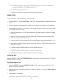
Washers and Dryers with Fifth Generation
Solid State Electronic Control Systems
Fabric/Cycles
Time
Heavy
Regular
Perm Press
Delicate
Hand Wash
Soak
14
12 Heavy
10
8 Normal
6
4 Light
Load Size
Temperature
Wash/Rinse
Hot/Warm
Hot/Cold
Warm/Warm
Warm/Cold
Cold/Cold
Extra Large
Medium
Small
Options
Super Wash
Extra Rinse
Rinse & Spin-High
Rinse & Spin-Low
Spin Only - High
Status
Fill/Wash
Rinse
Final Spin
LockOut
Cancel
Delay Hours
On
Select
Cycles/Temps
Reg/Heavy-High
Perm Press-Med
Delicate -Low
Fluff Air-No Heat
Tumble Press-Med
Damp Dry-High
On
Select
Automatic
or
Select
Timed
90 Min
70 Min
50 Min
30 Min
10 Min
Very Dry
More Dry
*Reg Dry
Less Dry
Least Dry
Select
Select
Select
Options
Status
Cycle Signal
Finish Guard
Drying
Cool Down
Finish Guard
LockOut
Select
LockOut
Cancel
Select
LockOut
Start
JOB AID
Part No. 4321848
Start
Delay
INTRODUCTION
This Job Aid, “Washers and Dryers with Fifth Generation Solid State Electronic Controls,” L-61, Part
No. 4321848 provides specific instruction for servicing the control system of Whirlpool-built three
speed direct drive washers and gas and electric dryers equipped with fifth generation fully solid state
electronic controls. These controls were introduced on Whirlpool washer model LSE9355BZO and
dryer model LE/GE9848BZO and KitchenAid washer model KAWE977BWHO and dryer model KE/
GYW977BWHO.
The Job Aid should be used in conjunction with the companion video tape , “Washers and Dryers with
Fifth Generation Solid State Electronic Controls,” Part No. 4321849.
All mechanical aspects of these units are identical to Whirlpool-build Direct Drive Washers and Gas
and Electric Dryers except as noted in ths Job Aid. For a complete description of repair procedures
refer to the Job Aids, “Direct Drive Washers” L-55, Part No. 787930 and “Dryer Mechanical Systems",
L-58, Part No. 4314557. Companion videos are also available for these Job Aid.
GOALS AND OBJECTIVES
The goal of this Job Aid is to provide specific information that will enable the service technician to
repair and maintain Whirlpool-built washers and dryers equipped with fifth generation solid state
electronic controls.
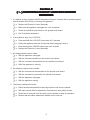
The objectives of this Job Aid are:
The service technician will •
•
Understand the function of the solid state electronic controls
Perform and interpret the diagnostic tests for the solid state electronic controls
TO THE INSTRUCTOR/INDEPENDENT STUDENT
This Job Aid is designed to be used with the video tape, “Washers and Dryers with Fifth
Genreration Solid State Electronic Control Systems,” Part No. 4321849. As you use this Job Aid
you will see a symbol that looks like this:
>>
It instructs you to view certain sections of the video tape. The section numbers you should view
appear in the lower left corner of the screen.
This symbol (.) appears next to the heading,. “Confirmation Of Understanding Exercises” which
appar at the end of various sections of the Job Aid. You will need a pencil to complete these exercises.
WHIRLPOOL CORPORATION ASSUMES NO RESPONSIBILITY
FOR ANY REPAIRS MADE ON OUR PRODUCTS BY ANYONE
OTHER THAN AUTHORIZED SERVICE TECHNICIANS
© 1995 Whirlpool Corporation, Benton Harbor, Michigan
TABLE OF CONTENTS
INTRODUCTION
III
TABLE OF CONTENTS
IV
SECTION 1 - EQUIPMENT AND SAFETY
1
SECTION 2 - INSTALLATION CONSIDERATIONS
3
SECTION 3 - THEORY OF OPERATION
7
Automatic Electronic Three Speed Direct Drive Washers
7
Electronic Electric and Gas Dryers
9
SECTION 4 - SERVICING WASHERS AND DRYERS
Automatic Electronic Three Speed Direct Drive Washers
11
11
Component Location and Access
11
Testing and Diagnosis
12
Servicing Procedures
18
Solid State Electronic Controls
18
Water Level Transducer
18
Electronic Electric and Gas Dryers
19
Component Locations and Access
19
Testing and Diagnosis
20
Servicing Procedures
23
Solid State Electronic Controls
SECTION 5 - TECH TIPS
23
25
Testing Procedures for Water level Transducer
25
Testing Procedures for LED Indicators
25
Product Speficiation and Warranty Information
25
Wiring Diagrams
26
-- NOTES --
>>
View Section 1 of the Video Tape
Section 1
EQUIPMENT AND SAFETY
EQUIPMENT
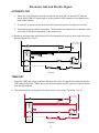
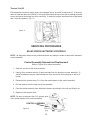
All tests/checks should be made with a VOM or DVM having a sensativity of 20,000 ohms per volt
DC or greater. Voltage check should be made with wires connected. (Figure 1)
Fig. 1
SAFETY
! WARNING
s
ELECTRICAL SHOCK HAZARD
Disconnect the unit from household electric supply before servicing.
Failure to do so could result in serious injury or death.
! CAUTION
s
ELECTROSTATIC DISCHARGE (ESD) SENSITIVE ELECTRONICS
Do not open the package containing the service replacement control assembly unitl it is time to
install it. ESD problems are present everywhere. ESD may damage or weaken the electronic
control assembly. The new control assembly may appear to work well after repair is finished,
but failure may occur at a later date due to ESD stress.
Use an anti-static wrist strap.
Connect wrist strap to green ground connection point or
unpainted metal in the appliance.
-ORTouch your finger repeatedly
to a green ground connection point
or unpainted metal in the appliance.
Before moving the part from its package,
touch the anit-static bag to a green ground connection
point or unpainted metal in the appliance.
Avoid touching electronic parts or terminal contacts;
handle electronic control assembly by edges only.
When repackaging a failed electronic control assembly in the anit-static bag,
observe above precautions.
1
-- NO
TES -NOTES
2
>>
View Section 2 of the Video Tape
Section 2
INSTALLATION CONSIDERATIONS
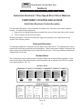
The most common cause of electronic control failure are the result of issues related to proper installation. Before servicing the appliance, perform the following checks:
·
Is the power cord firmly plugged into a live circuit with proper voltage?
·
Has a household fuse blown or circuit breaker tripped? Is the circuit on a time delay fuse?
·
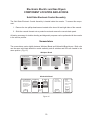
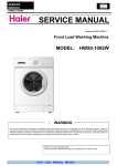
Is the washer or dryer in Lockout? Push and hold LOCKOUT select pad under OPTIONS for 5
seconds to release. (Figure 2)
·
Are both hot and cold water faucets open and water supply hoses unobstructed?
·
Check all connections before replacing components. Broken or loose wires and defective termi
nals can cause the same failure symptoms as a defective component.
1. Connectors: Look at the top of the connector for broken or loose wires. Check for wires not
pressed into the connector far enough to engage metal barbs.
2. Voltage: All voltage checks must be made with all connectors ATTACHED to the board(s).
3. Resistance: All resistance checks must be made with wiring harness or connectors
DISCONNECTED.
If the appliance appears to be properly installed and a problem still exists, further diagnosis is required.
Washer
Fabric/Cycles
Time
Heavy
Regular
Perm Press
Delicate
Hand Wash
Soak
14
12 Heavy
10
8 Normal
6
4 Light
Load Size
Temperature
Options
Wash/Rinse
Hot/Warm
Hot/Cold
Warm/Warm
Warm/Cold
Cold/Cold
Extra Large
Medium
Small
Status
Fill/Wash
Rinse
Final Spin
LockOut
Super Wash
Extra Rinse
Rinse & Spin-High
Rinse & Spin-Low
Spin Only - High
Cancel
Delay Hours
Select
Select
Select
LockOut
Start
Delay
Ü
On
Select
Select
Dryer
Reg/Heavy-High
Perm Press-Med
Delicate-Low
Fluff Air-No Heat
Tumble Press-Med
Damp Dry-High
On
Select
Automatic
or
Very Dry
More Dry
*Reg Dry
Less Dry
Least Dry
Timed
90 Min
70 Min
50 Min
30 Min
10 Min
Options
Status
Cycle Signal
Finish Guard
Drying
Cool Down
Finish Guard
LockOut
Cancel
Select
LockOut
Select
Fig. 2
3
Ü
Cycles/Temps
Start
INLET HOSES
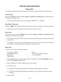
The rubber washers and inlet hoses on washers with 5th Generation Electronic Controls have been
installed in the factory. They will be found tucked into a cavity immediately below the inlet valve at the
back of the washer. (Fig. 3) Some effort will be required to separate the free ends of the hoses from
the plastic retainer inside the washer.
WATER INLET
VALVE
s
RUBBER WASHERS
AND INLET HOSES
ARE INSTALLED AT
FACTORY
s
Figure 3
4
Section 2
( . ) CONFIRMATION OF UNDERSTANDING
EXERCISES
1. If a washer or dryer equipped with 5th Generation Electronic Controls fails to operate properly,
what should be the first step in servicing the appliance?
o a. Replace the Electronic Control Assembly
o b. Make sure the appliance is plugged into a live receptacle.
o c. Check the individual components on the printed circuit board.
o d. Call for technical assistance.
2. If the washer or dryer is in LOCKOUT:
o a. Press and hold the LOCKOUT button down for 5 seconds.
o b. Unplug the appliance and wait 30 seconds before plugging it back in.
o c. Press and hold the CANCEL button down for 5 seconds.
o d. Replace the Electronic Control Assembly.
3. All voltage checks must be made:
o a. With the appliance unplugged.
o b. With the connectors attached to the printed circuit board.
o c. With the connector disconnected from the printed circuit board.
o d. While the appliance is running.
4. All resistance checks must be made:
o a. With the connectors disconnected from the printed circuit board.
o b. With the connectors connected to the printed circuit board.
o c. With the appliance unplugged.
o d. With the appliance running.
5. The factory installed inlet hoses:
o a. Should be disconnected before removing the free ends from the washer.
o b. Will require some effort to separate the free ends from their plastic retainer.
o c. Should not be removed from the cavity until the washer is ready for operation.
o d. Require that the rubber washers be installed on the inlet end.
5
-- NO
TES -NOTES
6
>>
View Section 3 of the Video Tape
Section 3
THEORY OF OPERATION
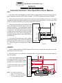
Automatic Electronic Three Speed Direct Drive Washers
FILL
1. The washer will fill automatically with warm water for approximately 90 seconds through the detergent dispenser when the START pad is touched. The STATUS display will indicate Fill/Wash.
2. The washer will then switch to regular fill through the Hot and Cold water inlet valves. The water
will enter the washer through the water inlet vacuum brake at the rear of the tub. The Hot and/or Cold
valves will energize depending on the water temperature selected.
N
3. The water level transducer will sense the water
level in the basket and send a signal to the microcomputer assembly. The microcomputer supplies
the water level transducer with 5VDC on pin 3 of
connector P1. The water level transducer outputs
a signal based on the amount of water in the basket between pins 1 and 3 which progressively illuminate the indicator LEDs on the LOAD SIZE options indicator.
4. If the water level reaches an overfill condition
mechanical contacts on the water level transducer
will remove the CPU 120V from pin 7 of connector
P1. This is the power to energize the fill valves.
(Fig. 4)
L1
CABINET
GROUND
NEUTRAL P10
N/C P11
COMAG P9
DET
DISP
COLD
9
8
FLOOD
HOT
N/C
N/C
7
6
5
4
PT HIGH
PT SIGNAL
PT LOW
3
2
1
COLD
HOT
VALVE
ASSEMBLY
WATER LEVEL
TRANSDUCER
WASHER CONTROL
ASSEMBLY
Figure 4
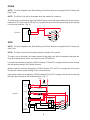
AGITATE
1. Once the basket is filled the COMAG applies 120V from P9 to energize the start capacitor and the
start winding of the drive motor.
2. Once the motor is up to speed the Centrifugal Switch will open disconnecting the start capacitor
and start winding.
NEUTRAL
L1
3. 120V is also applied directly to the
drive motor through Pin P8 (AG HI),
P13 (LMED) or P14 (LLOW) to control
the drive motor agitate speed. (Fig. 5)
4 When the agitate cycle is complete
voltage is removed from the drive
motor.
CABINET
GRO UND
NEUTRAL
N/C
COMAG
P1 0
P11
P9
START
CAPACITOR
L1
COMSP IN
LID
P3
P6
P4
LOW
SPIN
AG HI
P5
P7
P8
LLOW
LCOM
LMED
P14
P12
P13
CENTRIFUGAL
MOTOR S TART
SWITCH
START
NOTE:
•
•
•
The agitation speeds are:
High - 180 strokes per minute
Medium - 120 strokes per minute
Low - 80 strokes per minute
HIGH
MED
LOW
WASHER
CONTROL
ASS EMBLY
DRIVE MOTOR
Figure 5
7
DRAIN
NOTE: The Start Capacitor and Start Winding of the Drive Motor are energized from P9 during the
Drain Cycle.
NOTE: The Drain Cycle will be interupted when the washer lid is opened.
The drain cycle is activated by applying 120VAC directly to the high speed winding of the drive motor
between Pin P7 (Spin) and Pin P8 (Ag HI) to operate the drive motor through the high speed winding
in the reverse direction. (Fig. 6)
Figure 6
SPIN
P7
AG HI
P8
START
HIGH
MED
LOW
SPIN
DRIVE MOTOR
NOTE: The Start Capacitor and Start Winding of the Drive Motor are energized from P9 during the
Spin Cycle.
NOTE: The Spin Cycle will be interupted when the washer lid is opened.
The spin cycle is activated in the same manner as the drain cycle with the exception that there are
three spin speed options which are selected in the OPTIONS list.
Low speed is acheived by applying 120VAC between P14 and P7 to energize the drive motor through
the low speed winding in the reverse direction.
Medium speed is acheived by applying 120VAC between P13 and P7 to energize the drive motor
through the medium speed winding in the reverse direction.
High speed is acheived by applying 120VAC between P8 and P7 to energize the drive motor through
the high speed winding in the reverse direction. (Fig. 7)
NEUTRAL
L1
CABINET
GROUND
NEUTRAL
N/C
COMAG
P10
P11
P9
START
CAPACITOR
Figure 7
L1
COMSPIN
LID
P3
P6
P4
LID
SWITCH
LOW
SPIN
AG HI
P5
P7
P8
LLOW
LCOM
LMED
P14
P12
P 13
CENTRIFUGAL
MOTOR START
SWITCH
START
HIGH
MED
LOW
WASHE R
CONTROL
ASSEMBLY
DRIVE MOTOR
8
Electronic Gas and Electric Dryers
AUTOMATIC DRY
1. When any of the Automatic options are selected the dryer will run and the LED indicator
above the AUTOMATIC options will be lit along with the LED indicator for the specific automatic option chosen.
2. The sensor on the back of the dryer drum will sense the amount of moisture in the load.
3. Temperatures are sensed by a thermistor. The thermistor’s resistance will vary between 1000
ohms and 15,000 ohms depending on the temperature.
4. Based on the signal from the thermistor, the microcomputer will cycle the heat relay which energizes the heater coil. (Fig. 8)
L1
L2
N
NEUTRAL TERMINAL
LINKED TO CABINET
DRUM LAMP
DOOR
SWITCH
NEUTRAL
{
DOOR
SENSE
TEMP
THERMISTOR
MOIST
SENSOR
GROUND
MAIN
MOTOR
RELAY
THERMAL FUSE
NOT RESETTABLE
START
DRIVE MOTOR
HEAT
RELAY
THERMAL CUTOFF
NOT RESETTABLE
CONTROL
ASSEMBLY
HI-LIMIT
THERMOSTAT
HEATER
Figure 8
TIMED DRY
1. When the TIMED dry option is selected the dryer will run for the specific time selected and the
LED indicator above the TIMED options will be lit along with the LED next to the specific drying
time that was selected.
2. The moisture sensor on the back of the dryer drum is not active in Timed Dry. (Fig. 9)
L1
L2
N
NEUTRAL TERMINAL
LINK ED TO CABINET
DRUM LAMP
DOOR
SWITCH
NEUTRAL
{
DOOR
SE NSE
TEMP
THERMISTOR
MOIS T
GROUND
SE NSOR
MAIN
MOTOR
RELAY
THERMAL FUSE
NOT RES ETTABL E
START
DRIVE MOTOR
HEAT
RELAY
CONTROL
AS SEMBLY
THERMAL CUTOFF
NOT RES ETTABL E
Figure 9
9
HI-LIMIT
THERMOSTA T
HEATER
( . ) Section 3 - CONFIRMATION OF
UNDERSTANDING EXERCISES
1. The first portion of the washer FILL function is:
o a. A high pressure blast of hot water to clear the lines.
o b. A 90 second fill of hot and cold water through the detergent dispenser.
o c. A 90 second pause.
o d. None of the above.
2. The agitate speeds of the washer are:
o a. High - 180 SPM (Strokes per Minute), Medium - 120 SPM, Low - 80 SPM
o b. High - 180 RPM (Revolutions per Minute), Medium - 120 RPM, Low - 80 RPM
o c. There is no difference in agitate speeds.
o d. None of the above.
3. When drying clothes with the Automatic Option, drying time is determined by:
o a. The chosen automatic option and the moisture sensor at the back of the dryer drum.
o b. The chosen automatic option and the thermistor.
o c. The moisture sensor and the thermistor.
o d. The microcomputer's internal programming only.
4. If the washer should overfill:
o a. A microcomputer will interpret the water level and shut the fill valves off.
o b. A mechanical switch will open and shut the fill valves off.
o c. The water level transducer will malfunction.
o d. None of the above.
10
>>
View Section 4 of the Video Tape
Section 4
SERVICING WASHERS AND DRYERS
Automatic Electronic Three Speed Direct Drive Washers
COMPONENT LOCATION AND ACCESS
Solid State Electronic Control Assembly
The Solid State Electronic Control Assembly and Water level Transducer are located inside the
console. To access these components:
1. Remove the two philips head screws located at the lower left and right sides of the console.
2. Tilt the console into the service position.
All testing necessary for trouble shooting and diagnostic purposes can be perfomed with the
console in the service position.
Detergent Dispenser
The detergent dispenser is located in the front right corner under the lid. The dispenser can accommodate both liquid and powdered laundry detergents. When removing the cabinet, disconnect the
water supply hose located under a cover at the left rear of the top. Have a rag available to absorb any
residual water in the hose.
Nomenclature
The nomenclature varies slightly between Whirlpool Brand and Kitchenaid Brand washers. Both
units use the same solid state electronic control assembly and all switches and LEDs are located
in the same positions. (Fig. 10)
Whirlpool Brand
Fabric/Cycles
Time
Heavy
Regular
Perm Press
Delicate
Hand Wash
Soak
14
12 Heavy
10
8 Normal
6
4 Light
Load Size
Temperature
Wash/Rinse
Hot/Warm
Hot/Cold
Warm/Warm
Warm/Cold
Cold/Cold
Extra Large
Medium
Small
Options
Super Wash
Extra Rinse
Rinse & Spin-High
Rinse & Spin-Low
Spin Only - High
Status
Fill/Wash
Rinse
Final Spin
LockOut
Cancel
Delay Hours
On
Select
Select
Select
Select
Select
LockOut
Start
Delay
KitchenAid Brand
CYCLES
TIME
HEAVY
•
14
•
REGULAR
•
12
•
PERM PRESS
•
10
•
DELICATE
•
8
•
HANDCARE
•
6
•
SOAK
•
4
•
DELAY HOURS
ON
SELECT
LOAD SIZE
TEMPERATURE
OPTIONS
WASH/RINSE
•
HEAVY
NORMAL
LIGHT
SELECT
STATUS
• FILL/WASH
• Extra Large
• HOT/WARM
• EXTRA WASH
• RINSE
•
• HOT/COLD
• EXTRA RINSE
• FINAL SPIN
• Medium
• WARM/WARM
• RINSE/SPIN-HI
• LOCK OUT
•
• WARM/COLD
• RINSE/SPIN-LO
• Small
• COLD/COLD
• SPIN ONLY-HI
SELECT
SELECT
Figure 10
11
SELECT
START
LOCKOUT
DELAY
TESTING AND DIAGNOSIS
STARTING TEST MODE
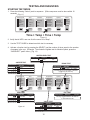
1. Press the following “Select” pads in sequence. (Entire sequence must be done within 10
seconds) (Fig. 11)
Fabric/Cycles
Time
Heavy
Regular
Perm Press
Delicate
Hand Wash
Soak
14
12 Heavy
10
8 Normal
6
4 Light
Load Size
Temperature
Wash/Rinse
Hot/Warm
Hot/Cold
Warm/Warm
Warm/Cold
Cold/Cold
Extra Large
Medium
Small
Options
Status
Super Wash
Extra Rinse
Rinse & Spin-High
Rinse & Spin-Low
Spin Only - High
Fill/Wash
Rinse
Final Spin
LockOut
Cancel
Delay Hours
On
Select
Select
Select
Select
LockOut
Select
Start
Delay
Ü
Ü
Time + Temp + Time + Temp
Figure 11
2. Verify that all LED’s are now lit at the sound of a “Beep”.
3. Use the TEST GUIDE to determine which test is necessary.
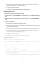
4. Activate a function test by pressing the SELECT pad the number of times equal to the number
of squares in the row. (Example: To activate the Agitate test for Meduim Speed, press the
“ON/SELECT” pad 2 times.) (Fig. 12)
WATER LEVEL TEST
Pad Presses
n
Selection
Small
Extra Large
Function
low
High
AGITATE TEST
Pad Presses
n
nn
nnn
n n n n
Selection
Heavy
Perm Press
Delicate
Off
DRAIN TEST
Function
Pad Presses
High
Medium
Low
Off
Fabric/Cycles
Time
Heavy
Regular
Perm Press
Delicate
Hand Wash
Soak
14
12 Heavy
10
8 Normal
6
4 Light
n
Function
Selection
Spin Only - Hi Drain
Unit will spin if enough water is drained
(toggle key off, then on)
Load Size
Temperature
Wash/Rinse
Hot/Warm
Hot/Cold
Warm/Warm
Warm/Cold
Cold/Cold
Extra Large
Medium
Small
Options
Super Wash
Extra Rinse
Rinse & Spin-High
Rinse & Spin-Low
Spin Only - High
Status
Fill/Wash
Rinse
Final Spin
LockOut
Cancel
Delay Hours
On
Select
Select
Select
Select
Select
LockOut
SPIN TEST
Pad Presses
nn
nnn
nnnn
nnnnn
Selection
4 minutes
6 minutes
8 minutes
Off
FILL TEST
Function
Pad Presses
Low
Medium
High
Off
Selection
Function
This key toggles between all LEDs on
or low water level fill
VALVE TEST
Pad Presses
Figure 12
Start
Delay
n
nn
nnn
n n n n
12
Function
Selection
Warm/Warm Det/Hot/Cold
Cold/Cold
Cold
Hot/Cold
Hot
Off
Off
LID AND SPIN TEST
1. Make sure the washer lid is closed before starting test.
2. Press “SELECT” pad under Temperature four times to turn off all water valves. (NOTE: Display
will show “Small” indicator light.)
Lid Switch Test
1. Press the “SELECT” pad under TIME unitl the “4” indicator LED is lit. the washer should start to
spin.
2. If the washer is not spinning, open and close the lid to reset the Neutral Drain Mechanism. If the
washer is still not spinning go to step 4.
3. If the washer is spinning, the lid switch is functioning correctly. Continue to Low Speed Spin
Test.
4. If the washer is not spinning:
a. Unplug the washer from household power supply.
b. Open the console and disconnect the lid switch connector on the cabinet.
c. Measure continuity between the outside pins on the 3-pin
connector socket with an ohm meter. (Fig. 13)
d. Verify that, with the lid closed, the switch is closed (0 ohms)
e. Verify that, with the lid open, the switch is open (~ ohms)
f.
If either conditions in d. or e. are not true, replace the lid
switch. Continue to Low Speed Spin Test.
Figure 13
Low Speed Spin Test
This test should be conducted with the lid switch closed.
1. Press the “SELECT” pad under TIME until the 4 indicator LED is lit. the washer should start to
spin.
2. Low speed spin is functioning properly if the washer is spinning. Go to Medium Speed Spin Test.
3. If washer is not spinning:
a. Unplug washer from 120VAC household power supply.
b. Open the console and inspect for loose connections. Disconnect and reconnect all wires
from the electronic control assembly.
c. Close the console, plug the washer into the household power supply and repeat steps 1 & 2.
13
d. If the washer still does not spin, leave the washer plugged in and check for 120VAC from
connectors P14 (W-OR) to P7 (W-BK) during step 1.
e. If 120VAC is present, check motor.
f.
If 120VAC is not present, replace the electronic control assembly.
Medium Speed Spin Test
This test should be conducted with the lid switch closed.
1. Press the “SELECT” pad under TIME until the "6" indicator LED is lit. The washer should start to
spin.
2. Medium speed spin is functioning properly if the washer is spinning. Go to High Speed Spin
Test.
3. If washer is not spinning:
a. Unplug washer from 120VAC household power supply.
b. Open the console and inspect for loose connections. disconnect and reconnect all wires from
the electronic control assembly.
c. Close the console, plug the washer into the household power supply and repeat steps 1 & 2.
d. If the washer still does not spin, leave the washer plugged in and check for 120VAC from
connectors P13 (W-V) to P7 (W-BK) during step 1.
e. If 120VAC is present, check motor.
f.
If 120VAC is not present, replace the electronic control assembly.
High Speed Spin Test
This test should be conducted with the lid switch closed.
1. Press the “SELECT” pad under TIME until the "8" indicator LED is lit. The washer should start to
spin.
2. High speed spin is functioning properly if the washer is spinning
3. If washer is not spinning:
a. Unplug washer from 120VAC household power supply.
b. Open the console andinspect for loose connections. Disconnect and reconnect all wires from
the electronic control assembly.
c. Close the console, plug the washer into the household power supply and repeat steps 1 & 2.
14
d. If the washer still does not spin, leave the washer plugged in and check for 120VAC from
connectors P8 (BU) to P7 (W-BK) during step 1.
e. If 120VAC is present, check motor.
f.
If 120VAC is not present, replace the electronic control assembly.
DRAIN TEST
This test should be conducted with the lid switch closed.
1. Press the “SELECT” pad under OPTIONS. (The “Small” and “Warm/Warm” indicator LEDs should
be lit.)
2. The drain function is working properly if the motor is running and the water level is decreasing.
3. If the washer will not drain (eg.: The motor is not running; the water level stays the same or takes
an unusually long time to drain):
a. Unplug the washer from 120VAC household power supply and check for kinked or clogged
drain hose.
b. Open the console and inspect for loose connections. Disconnect and reconnect all wires
from the electronic control assembly.
c. Close the console, plug the washer into the household power supply and repeat steps 1 & 2.
d. If the washer still does not drain, open the console and check for 120VAC from connectors P8
(BU) and P7 (W-BK).
e. If 120VAC is present and the motor is running, replace the pump.
f.
If 120VAC is present and the motor is not running, check motor.
g. If 120VAC is not present, replace the electronic control assembly.
AGITATE TEST
Press the “SELECT” pad under TEMPERATURE four times to turn off all water valves. (The “Small”
indicator LED should be lit.)
High Speed Agitate Test
1. Press the “SELECT” pad under FABRIC/CYCLES until the “Heavy” indicator LED is lit. The
washer should start to agitate.
2. High speed function is operating properly if the washer is agitating. Continue to Medium Speed
Agitate Test.
3. If the washer is not agitating:
a.Unplug the washer from 120VAC household power supply.
15
b. Open the console and inspect for loose connections. Disconnect and reconnect all wires
from the electronic control assembly.
c. Close the console, plug the washer into the household power supply and repeat steps 1 & 2.
d. If the washer still does not agitate, open the console and check for 120VAC from connectors
P8 (BU) and P10 (W) during step 1.
e. If 120VAC is present, check motor.
f.
If 120VAC is not present, replace the electronic control assembly.
Medium Speed Agitate Test
1. Press the “SELECT” pad under FABRIC/CYCLES until the “Perm Press” indicator LED is lit. The
washer should start to agitate.
2. Medium speed function is operating properly if the washer is agitating. Continue to Low Speed
Agitate Test.
3. If the washer is not agitating:
a. Unplug the washer from 120VAC household power supply.
b. Open the console and inspect for loose connections. Disconnect and reconnect all wires
from the electronic control assembly.
c. Close the console, plug the washer into the household power supply and repeat steps 1 & 2.
d. If the washer still does not agitate, open the console and check for 120VAC from connectors
P13 (W-V) and P10 (W) during step 1.
e. If 120VAC is present, check motor.
f.
If 120VAC is not present, replace the electronic control assembly.
Low Speed Agitate Test
1. Press the “SELECT” pad under FABRIC/CYCLES until the “Delicate” indicator LED is lit. The
washer should start to agitate.
2. Low speed function is operating properly if the washer is agitating.
3. If the washer is not agitating:
a. Unplug the washer from 120VAC household power supply.
b. Open the console and inspect for loose connections. Disconnect and reconnect all wires
from the electronic control assembly.
c. Close the console, plug the washer into the household power supply and repeat steps 1 & 2.
16
d. If the washer still does not agitate, open the console and check for 120VAC from connectors
P14 (W-O) and P7 (W-BK) during step 1.
e. If 120VAC is present, check motor.
f.
If 120VAC is not present, replace the electronic control assembly.
FILL AND DISPENSE TEST
Press the “SELECT” pad under STATUS. (The “Small” and “Warm/Warm” indicator LEDs should be
lit.)
No Fill and/or No Dispense
If the washer is not filling from all three valves:
1. Unplug the washer from 120VAC household power supply.
2. Open the console and inspect for loose connections. Disconnect and reconnect all control
connections that are shown in the “Fill and Dispense” strip circuit.
3. Close the console, reconnect the washer to the household power supply and repeat steps 1 & 2.
4. Use a voltmeter to verify the presence of 120VAC bwtween these test points:
•
•
•
P1 Pin 8 (Y-R) and P10 (W)
P1 Pin 6 (BR-R) and P10 (W)
P1 Pin 8 (W-R) and P10 (W)
Output to the cold valve
Output to the hot valve
Output to the dispenser valve
5. If 120VAC is present on all three valves, press “Cancel” and go to Washer Overfills.
6. If 120VAC is not present on any of the valves, replace the electronic control assembly.
Washer Overfills
1. Observe the water level to determine if the valves turn the water off when the level reaches the
bottom seam of the agitator auger (less than 10 inches from the bottom of the tub, no more than 2
inches above the seam.)
2. If filling continues more than an inch above this point, the washer has overfilled.
a. Press “Cancel” to stop the test and unplug the washer from 120VAC household power supply.
b. Open the console and inspect for loose connection. Disconnect and reconnect all wires
between the water level transducer and the electronic control assembly.
c. Close the console and plug the washer in. Enter “Diagnostic Test Mode.”
d. Press the “SELECT” pad under OPTIONS to drain the remaining water from the tub.
e. Repeat steps 1 and 2. If the washer still overflills, replace the water level transducer.
f.
Repeat steps 1and 2. If the washer still overfills, replace the electronic control assembly.
17
SERVICING PROCEDURES
SOLID STATE ELECTRONIC CONTROLS
NOTE: All diagnostic tests must be performed before any attempt is made to remove the electronic
control assembly.
Control Assembly Removal and Replacement
Refer to Figure 14 for these procedures.
1. Open the console to the service position. The User Cards Holder should be removed first to avoid
damage.
2. Unplug all five connectors from the control assembly. (A slotted screwdriver may be used between the 9-pin connector and the locking tab to aid in removal.)
3. Disconnect the ground wires (G-Y) from the metal chassis of the control assembly.
4. Pull the retainer from the right end of the assembly.
5. Free the control assembly from the plastic brackets by sliding it to the left and lifting it out.
6. Replace is the reverse order.
NOTE: Be sure to reconnect the (G-Y) ground wires to the metal chassis of the control assembly.
Water Level Transducer Removal/Replacement
Refer to Figure 14 for these procedures.
1. Open the console to the service position.
2. Remove the pressure hose tubing.
3. Unplug all connectors from the transducer.
4. Push down while pushing in on the nearest side mounting arm to remove.
5. Replace in reverse order.
WATER LEVEL TRANSDUCER
Figure 14
CONTROL ASSEMBLY
18
Electronic Electric and Gas Dryers
COMPONENT LOCATION AND ACCESS
Solid State Electronic Control Assembly
The Solid State Electronic Control Assembly is located inside the console. To access this component:
1. Remove the two philips head screws located at the lower left and right sides of the console.
2. Slide the console forward onto a protective mat and remove the console back panel.
All testing necessary for trouble shooting and diagnostic purposes can be perfomed with the console
in the service position.
Nomenclature
The nomenclature varies slightly between Whirlpool Brand and KitchenAid Brand dryers. Both units
use the same solid state electronic control assembly and all switches and LEDs are located in the
same position. (Fig. 15)
Whirlpool Brand
Cycles/Temps
Reg/Heavy-High
Perm Press-Med
Delicate-Low
Fluff Air-No Heat
Tumble Press-Med
Damp Dry-High
Automatic
or
Very Dry
More Dry
*Reg Dry
Less Dry
Least Dry
On
Select
Timed
90 Min
70 Min
50 Min
30 Min
10 Min
Options
Status
Cycle Signal
Finish Guard
Drying
Cool Down
Finish Guard
LockOut
Cancel
Select
LockOut
Select
Start
KitchenAid Brand
CYCLES/TEMPS
AUTOMATIC
TIMED
• REGULAR-HEAVY/HI
STATUS
OPTIONS
•
CYCLE SIGNAL
•
DRYING
•
SMOOTH GUARD
•
COOL DOWN
• PERMT PRESS/MED
VERY DRY
•
90 MIN
• DELICATE/LOW
MORE DRY
•
70 MIN
•
SMOOTH GUARD
• AIR TUMBLE/NO HEAT
*REG DRY
•
50 MIN
•
LOCK OUT
• QUICK PRESS/MED
LESS DRY
•
30 MIN
• DAMP DRY/HI
LEAST DRY
•
10 MIN
ON
SELECT
CANCEL
SELECT
LOCK OUT
SELECT
Figure 15
19
START
TESTING AND DIAGNOSIS
Diagnostics
The following problems can be diagnosed by observing the indicator LEDs on the control panel.
Power Failure
When the 3 STATUS LEDs are flashing: Drying + Cool Down + Finish Guard, a power failure may
have occurred during a cycle.
•
The flashing LEDs can be turned off by pressing “ON/SELECT” or “CANCEL”.
Open/Short Thermistor
When the TIMED LED is flashing, the thermistor or the wiring to the thermistor is open or shorted.
•
The thermistor must be replaced or the wiring fault must be corrected.
Door Open
When any one of the following STATUS LEDs is flashing: Drying, Cool Down or Finish Guard, the
door has been opened during a cycle.
•
Close the door and press “START” within five minutes of opening the door in order to continue the
current cycle.
•
The electronic control will turn off automatically if the door is left open for more than five minutes
or if “START” is not pressed within five minutes of closing the door.
Motor Test
If the motor will not start, check the following:
-
Line Voltage (120VAC)
Harness/Connections
Motor Relay
Thermal Fuse
-
Motor
Door Switch (120VAC contacts)
Control Assembly
1. If the Lockout LED is lit, press and hold “SELECT/LOCKOUT” pad under OPTIONS for 5 seconds. The Lockout LED will turn off.
2. Press “ON/SELECT” pad if the LEDs are on and go to step 4.
3. If all LEDs are off:
a. Check the ‘120VAC supply voltage to the electronic control assembly. (W to BK)
b. If 120VAC is present and the harness connections are OK, replace the electronic control
assembly.
4. Press “START”
20
a. If the motor does not start and there is an “Invalid Tone”, check the door switch. (D to D1)
b. If the motor does not start and the Drying LED lights up, check the motor and thermal fuse.
c. If the motor still does not start, check the motor relay (BK to BU)
d. If 120VAC is present and the harness connections are OK, replace the electronic control
assembly.
No Heat Test
If the heater will not turn on, check the following:
-
Line Voltage (120VAC)
Harness/Connections
Heat Relay
Thermal Cut-Off
Hi-Limit Thermostat
-
Heater
Centrifugal Switch
Thermistor
Control Assembly
1. Press “ON/SELECT” and “START”. The Drying LED will come on and the motor will start. the
heater should turn on after a 4 second delay.
2. If there is no heat, check the heat relay.
a. If 0VAC, check the centrifugal switch, heater, hi-limit thermostat and thermal cut-off.
b. If 120VAC, replace the thermistor and check harness connections.
Heat In Fluff Test
If the dryer heats in Fluff Air, check the following:
-
Harness/Connection
Heater
-
Heat Relay
Control Assembly
1. Press “ON/SELECT” until Fluff Air LED indicator is lit.
2. Press “START”
3. If heater is on, check the harness connections and heater.
a. Check the heater relay on the control board (BK to R)
b. If 0VAC, replace the electronic control assembly.
Shut Off Test
If the dryer will not shut off, check the following:
-
Harness/Connection
Sensor Strip
-
Motor Relay
Control Assembly
1. Remove clothes from the dryer and press “ON/SELECT”.
21
2. Select Automatic - Less Dry and press “START”.
3. If the motor will not stop after 16 seconds, check sensor strip (Y-R to G-Y).
a. If 0 ohms with no load, check for a short in the sensor or the Y-R wire.
b. If infinite ohms (Y-R to G-Y should be infinite with no load,) replace the electronic control
assembly.
If the dryer shuts off too soon in an “Automatic” cycle, check the following:
-
Harness/Connection
Sensor Strip
Control Assembly
1. Short the sensor strip together and press “ON/SELECT”.
2. Select Automatic - Less Dry and press “START”.
3. If the motor stops after a 16 second delay, short Y-R at the control assembly.
4. Repeat steps 1 & 2.
a. If the motor runs more that 16 seconds, repair or replace the sensor and the Y-R wire.
b. If the motor stops after a 16 seeond delay, replace the electronic control assembly.
Heater Box Hi-Limit Thermostat Test
1. Remove the thermistor from the fan housing and plug the hole.
NOTE: Protect the thermistor and leads from grounding against any metal parts.
2. Completely block the exhaust outlet.
3. Turn the dryer on and allow the hi limit thermostat to cycle once. Measure the time required for
the hi-limit thermostat to trip. Nominal times are anywhere from 21 to 90 seconds.
4. Reinstall the thermistor after testing the hi-limit thermostat.
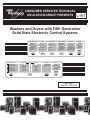
Thermistor Test
1. Check the wiring to the thermistor.
2. Disconnect the thermistor and check the internal resistance. (Figure 16)
Thermal Fuse
A thermal fuse is used on fifth generation electronic electric dryers.
The thermal fuse is wired in series in the L1 line of the dryer. If the thermistor
fails, the thermal fuse opens and shuts off power to the motor and heater to
prevent overheating. Once the thermal fuse has opened, it must be replaced.
22
THERMISTOR
RESISTANCE
TEMP
Ω
°F
19.9K
50°
15.3K
60°
11.9K
70°
9.2K
80°
7.4K
90°
5.7K
100°
4.7K
110°
3.7K
120°
3.1K
130°
2.4K
140°
Figure 16
Thermal Cut-Off
Fifth generation electronic electic dryers are equipped with a “one-shot” thermal cut-off. If the dryer
does not heat and there are 240VAC to the dryer, disconnect the dryer from the household electrical
source and check the thermal cut-off for continuity. If continuity is open, the thermal cut-off has failed
and it must be replaced. (Fig. 17)
Figure 17
SERVICING PROCEDURES
SOLID STATE ELECTRONIC CONTROLS
NOTE: All diagnostic tests must be performed before any attempt is made to remove the electronic
control assembly.
Control Assembly Removal and Replacement
Refer to Figure 18 for these procedures
1. Open the console to the service position.
2. Unplug 9-pin connector and the 2 relay terminals from the electronic control assembly. (A
slotted screwdriver may be used between the 9-pin connector and locking tab to aid in removal.)
3. Disconnect the ground wires (G-Y) from the metal chassis of the control assembly.
4. Pull the retainer from the right end of the assembly.
5. Free the control assembly from the plastic brackets by sliding it to the left and lifting it out.
6. Replace is the reverse order.
NOTE: Be sure to reconnect the (G-Y) ground wires
to the metal chassis of the control assembly.
CONTROL ASSEMBLY
Figure 18
23
( . ) Section 4 - CONFIRMATION OF
UNDERSTANDING EXERCISES
1. To enter the test mode on 5th generation washers:
o a. Press the ON/SELECT button four times.
o b. Press TIME Select + TEMP Select + TIME Select + TEMP Select within 10 seconds.
o c. Press the ON/SELECT and the CANCEL buttons twice.
o d. Unplug the washer and wait 30 seconds before plugging it back in.
2. To enter the test mode on 5th generation dryers:
o a. Press the ON/SELECT button four times.
o b. Press the Automatic or Timed SELECT button four times.
o c. Press the ON/SELECT and the CANCEL buttons twice.
o d. There is not a test mode for the dryer.
3. The electronic control boards on 5th generation washers and dryers:
o a. Have servicable parts mounted on them.
o b. Should be replaced any time the appliance is serviced.
o c. Should not be replaced until all diagnostic tests have been conducted.
o d. None of the above.
4. 5th generation washers and dryers are:
o a. Substantialy different mechanically than previous models.
o b. Mechanically nearly the same as previous models.
o c. None of the above.
o d. Hopelessly complex.
24
>>
View Section 5 of the Video Tape
Section 5
TECH TIPS
TESTING PROCEDURE FOR WATER LEVEL TRANSDUCER
Washers equipped with 5th Generatiuon Electronic Controls use a solid state electronic pressure transducer to
convert air pressure created in the pressure dome to a low voltage square wave signal to determine water level.
The microcomputer on the electronic control board translates the varying frequency of the square wave into
inches of water in the tub.
This test can be conducted to determine proper operation of the pressure transducer and the control board.
1. Use a VOM and check for the presence of 5VDC between pins 1 and 3 of P1. If there is no voltage
present, replace the control board.
2. With the washer empty, use a VOM and check for the present of .7VDC between pins 1 and 2 of P1.
If no voltage is present, replace the pressure transducer.
NOTE: When using an analog VOM (with a needle movement meter) the voltage may not read exactly as
indicated above. The voltage reading is dependent on the method any particular meter uses to average the
square wave frequency to derive the voltage reading. As a result, a chart can not be provided to confirm water
level verses voltage reading.
When using a digital VOM (with an LED display) the voltage reading is again dependent on the method used to
derive the voltage reading by averaging the frequency of the square wave signal. Some digital VOMs can
directly read the signal frequency, but this is rare. As a result, a chart can not be provided to confirm water level
verses voltage reading.
Because voltage readings may not read exact factory specifications, this test is only to confirm that the output
between low level (.7VDC) and the high level (5VDC) is present and that the transducer is working. It does not
confirm the accuracy of the water level readings.
Current water levels can only be determined by running a wash cycle and observing the actual water level in the
tub. These levels are determined by software in the microcomputor and are not adjustable.
TESTING PROCEDURES FOR LED INDICATORS
If a particular LED indicator on the electronic control board does not light when a selection is made a VOM can
be used to determine if DC voltage is present across the LED leads.
If an analog VOM is used the needle should show a positive voltage reading if the LED is operational.
If a digital VOM is used it will not show a DC voltage reading on the normal DC voltage setting. The digital VOM
should be equipped with a diode setting to properly check the LEDs.
PRODUCT SPECIFICATIONS AND WARRANTY
INFORMATION SOURCES
FOR WHIRLPOOL PRODUCTS: 1-800-253-1301
FOR KITCHENAID PRODUCTS 1-800-422-1230
FOR TECHNICIAL ASSISTANCE WHILE AT THE CUSTOMER'S HOME CALL:
1-800-253-2870
Have your store number ready to identify you as an Authorized Servicer
25
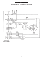
WIRING DIAGRAMS
THREE SPEED AUTOMATIC WASHER
26
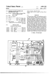
AUTOMATIC DRYER
ELECTRIC
GAS
CONFIRMATION OF UNDERSTANDING EXERCISES
ANSWER SHEET
SECTION 2
SECTION 3
SECTION 4
1.
2.
3.
4.
5.
1.
2.
3.
4.
1.
2.
3.
4.
B
A
B
A
B
B
A
A
B
27
B
D
C
B
28