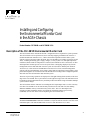
1
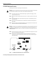
Doc. No. 78-0899-03
Installing and Configuring
the Environmental Monitor Card
in the AGS+ Chassis
Product Number: CSC-ENVM= and MC-ENVM-V2.2=
Description of the CSC-ENVM Environmental Monitor Card
The CSC-ENVM card is included in all AGS+ configurations and is required for system operation.
The CSC-ENVM is not an optional card, and is currently shipping with Microcode Version 2.2
(Product Number MC-ENVM-V2.2=), which is backward compatible with the earlier system
software versions referred to in this document. The CSC-ENVM serves a number of purposes for the
AGS+, including monitoring power supply voltages ( 5 volts [V] and 12V) and high temperature
conditions (chassis intake air temperature is measured, and exhaust air flow is measured). Air flow
and temperature monitors provide two levels of protection: warning flags displayed by network
management software and faults that cause the system to be shut down. With System Software
Version 8.3(3) or later and CSC-ENVM Microcode Version 2.2 or later, network management
software can also poll and display power supply voltage and air temperature to help predict system
problems through the use of sensors on the CSC-ENVM. An overvoltage fault or a high-temperature
fault will cause the CSC-ENVM to shut down the system.
The states of processing operations are displayed on four light emitting diodes (LEDs) on the front
edge of the CSC-ENVM. The 15-pin connector on the right front edge of the CSC-ENVM card can
be attached to the optional Flash memory card that provides nonvolatile storage of bootable multiple
system software images.
The CSC-ENVM card also functions as an intelligent slave input/output card, as well as a memory
card. The CSC-ENVM serves the same memory functions as the CSC-MT card, thus making
additional Multibus memory cards unnecessary in the AGS+. The CSC-ENVM provides
64 kilobytes (KB) of Multibus memory and 64 KB of nonvolatile random access memory
(NVRAM). (See the note in the section “Replacing the CSC-ENVM Card.”)
Note The show environment command is available as of System Software Version 8.3(3) or later.
The show environment last command is available as of System Software Version 9.0 or later. Each
command requires CSC-ENVM Microcode Version 2.2 (MC-ENVM-V2.2=) or later.
Copyright © 1994
Cisco Systems, Inc.
All rights reserved.
1
About this Document
About this Document
Before beginning any procedures, read the following outline and the sections you will be using.
•
Site Requirements and Specifications, page 3
— AGS+ Site Environment, page 3
— AGS+ System Environmental Reports, page 4
Displaying the Reason for the Last Environmental Shutdown, page 5
Preventive Site Configuration—Avoiding Shutdowns, page 6
— Troubleshooting an Air-Related Shutdown, page 7
•
Replacing the CSC-ENVM Card, page 8
— Uploading the Configuration File to a TFTP File Server, page 8
— CSC-ENVM Replacement Procedure, page 10
•
EPROM Replacement for the CSC-ENVM Card, page 11
— Tools Required, page 11
•
•
Testing the Installation, page 13
Downloading the Configuration File from a TFTP File Server, page 14
Preventing Electrostatic Discharge Damage
Electrostatic discharge (ESD) damage occurs when electronic printed circuit cards are improperly
handled and can result in complete or intermittent failures. ESD can impair electronic circuitry and
equipment. Follow ESD prevention procedures when removing and replacing cards.
Following are steps for safely handling printed circuit cards:
Step 1
Slip on an ESD-preventive wrist strap, ensuring that it makes good skin contact.
Step 2
Connect the strap to an unpainted chassis frame surface or another proper grounding point
or chassis surface to safely channel unwanted ESD voltages to ground.
Step 3
Use the edge ejectors to remove the card. Handle the card by its sides. Place the card on an
antistatic surface or in a static shielding bag. To prevent further damage to the card by ESD
voltages, defective cards must remain in the static shielding bag when returned for repair
or replacement.
Step 4
Handling the new card by its edges only, insert it into the chassis. Avoid contact between
the card and clothing. The wrist strap only protects the card from ESD voltages on the body;
ESD voltages on clothing can still damage the card.
Note To ensure that the resistor in the ESD strap is providing proper ESD protection, use an
ohmmeter to check the ESD wrist strap. For adequate safety and ESD protection the measurement
should be in the range 1 to 10 mega ohms.
2 Installing and Configuring the Environmental Monitor Card in the AGS+ Chassis
Site Requirements and Specifications
Site Requirements and Specifications
The successful use of the CSC-ENVM card in the AGS+ chassis requires that the chassis be installed
and maintained to preclude unintended shutdowns.
The AGS+ chassis has an internal blower fan that pulls air through the card cage from left to right
(with the chassis front toward you). If either the intake or exhaust vents are blocked in any way, this
air-cooling function will be impaired and the CSC-ENVM, sensing this, will shut the chassis down.
If the temperature of the air being drawn into the chassis is already higher than desirable, the air
temperature inside the chassis may be too high. This condition can occur when the wiring closet or
rack in which the chassis is mounted is not ventilated properly, when the exhaust of one chassis (or
other electronic device) is placed so it enters the air intake vent of the chassis, or when the chassis
is the top unit in an unventilated rack. With any of these conditions, a shutdown by the CSC-ENVM
can be induced.
The chassis is designed to operate in a level, dry, clean, well-ventilated, and air-conditioned
environment. While chassis shutdown due to a fault or failure is one of the designed purposes of the
CSC-ENVM, unnecessary shutdowns due to air intake blockage and poor external ventilation can
and should be avoided.
Note The AGS+ can be installed in wiring closets and rack systems as long as the above
prerequisites are observed before installation and are maintained throughout chassis operation.
AGS+ Site Environment
The AGS+ chassis can be used as a tabletop or rack-mounted system in a data processing or lab
environment. Because the large cooling fan in the AGS+ chassis is somewhat noisy (approximately
60 decibels), the chassis is designed for unattended or computer room use.
General site requirements for the AGS+ chassis are as follows:
•
•
•
Operating temperature range: 32 to 104 F (0 to 40 C)
Operating humidity range: 5 to 95%, noncondensing
Air flow: Depending upon the temperature and cooling capability of your site, the chassis will
require a minimum amount of clearance on all sides to prevent the chassis from taking in the
exhaust (heated) air of other equipment.
Installing and Configuring the Environmental Monitor Card in the AGS+ Chassis 3
Site Requirements and Specifications
AGS+ System Environmental Reports
The AGS+ system runs a routine that polls the CSC-ENVM card for voltage and temperature
readings. The system obtains these statistics from the CSC-ENVM at a rate of once a minute and
stores them in a buffer. With System Software Version 8.3(3) or later and CSC-ENVM Microcode
Version 2.2 or later, you can display the contents of this buffer with the show environment
command. The resulting display contains current intake and exhaust air temperatures, shutdown
thresholds, and voltage measurements of DC lines.
Following is sample output of the show environment command:
Router# show environment
Environmental controller firmware version 2.2
Serial number is 00225259, calibrated on 5-10-94, by technician mpo
Internal temperature measured 27.0(C), shuts down at 43.0(C)
Air flow appears good.
+5 volt line measured at 5.061(V)
+12 volt line measured at 12.070(V)
-12 volt line measured at -12.034(V)
-5 volt line measured at -4.915(V)
Router#
Automatic Warning Messages
If a measurement exceeds desired margins, but has not exceeded fatal margins, a warning message
is printed to the system console. The system software queries the CSC-ENVM card for
measurements once a minute, but warnings for a given test point are printed at most once every four
hours.
If a measurement exceeds the desired margins at any time within a four-hour period, an automatic
warning message appears on the console. As noted, the user may query the CSC-ENVM using show
environment at any time to determine if a measurement is at the warning level.
Following is an example of the message displayed on the system console when a measurement has
exceeded an acceptable margin:
Router#
ENVIRONMENTAL WARNING: Airflow appears marginal.
Following is an example of a message displayed on the system console when an ambient temperature
measurement has exceeded an acceptable margin, and the temperature reading is given:
Router#
ENVIRONMENTAL WARNING: Internal temperature measured 41.3(C)
Following is an example of a message displayed on the system console when a voltage measurement
has exceeded an acceptable margin, and the voltage reading is given:
Router#
ENVIRONMENTAL WARNING: +5 volt testpoint measured 5.310(V)
4 Installing and Configuring the Environmental Monitor Card in the AGS+ Chassis
Site Requirements and Specifications
Shutdown Messages and Thresholds
If voltage or temperature exceed maximum or fatal thresholds (shown in Table 1), the system
displays the following type of message:
Router#
SHUTDOWN: air flow problem
If a temperature or voltage test point reaches the warning level, a message is printed to the system
console. If a test point reaches the fatal threshold, the CSC-ENVM performs as follows:
1 The last measured values from each of the six test points are saved to internal NVRAM.
2 The system software is interrupted, and a shutdown message is printed on the system console.
3 The power supply is shut off after a few milliseconds of delay.
Caution If the internal temperature reaches the 43 C threshold, the chassis is completely shut down.
The internal temperature of the system exceeds the external ambient temperature by approximately
3 C. The system cannot be restarted until the internal air temperature returns to an ambient level, and
the power switch is toggled. If the shutdown was due to a voltage problem, toggling the switch may
not be sufficient to bring the system back up, and a larger problem may be indicated.
Displaying the Reason for the Last Environmental Shutdown
If a CSC-ENVM induced shutdown occurs, the CSC-ENVM logs the last measured value from each
of the six test points to internal NVRAM. Only the last set of these six measurements are stored at
any one time. With System Software Version 9.0 or later and CSC-ENVM Microcode Version 2.2
or later, these measurements can be printed to the console using the show environment last
command.
Following is sample output of the show environment last command:
Router# show environment last
Environmental controller firmware version 2.2
Serial number is 00225259, calibrated on 5-10-94, by technician mpo
Internal temperature measured 27.0(C), shuts down at 43.0(C)
Air flow appears good.
+5 volt line measured at 5.061(V)
+12 volt line measured at 12.070(V)
-12 volt line measured at -12.034(V)
-5 volt line measured at -4.915(V)
LAST Environmental Shutdown Measurements:
Internal temperature was 24.0(C)
Air flow sensor was good
+5 volt line was 4.990(V)
+12 volt line was 9.900(V)*
-12 volt line was -11719(V)
-5 volt line was -4.926(V)
Router#
Note An asterisk (*) appends the test point indicating the failure. In this example, the +12 volt line
dropped to 9.900(V) causing the shutdown.
Installing and Configuring the Environmental Monitor Card in the AGS+ Chassis 5
Site Requirements and Specifications
Table 1
Air Temperature and Voltage Warning and Fatal Thresholds
Designation
Warning Threshold
Fatal Threshold
Internal intake air at the
sensor (tolerance is +/- 3 C)
40 C
43 C
Air flow (exhaust)
Warning Message
58 C
+5 volt supply
+/-5%
+/-10%
+12 volt supply
+/-10%
+/-15%
-12 volt supply
+/-10%
+/-15%
-5 volt supply
+/-5%
+/-10%
Preventive Site Configuration—Avoiding Shutdowns
The proper location of the AGS+ chassis and the layout of your equipment rack or wiring room are
essential for proper system operation. Equipment placed too close together and inadequately
ventilated can cause system malfunctions and shutdowns. In addition, chassis panels made
inaccessible by poor equipment placement can make system maintenance difficult.
If you are currently experiencing shutdowns or unusually high errors with your existing equipment,
the following general precautions may help you isolate the cause of failures and prevent future
problems.
Read and follow the precautions below when planning your site layout and equipment locations; this
will help avoid future equipment failures and reduce the likelihood of environmentally-caused
shutdowns.
General Precautions
•
The CSC-ENVM card now provides over temperature and over/under voltage warnings and
reports.
•
Remember that electrical equipment generates heat and ambient room temperature alone may not
be adequate to cool equipment to acceptable operating temperatures.
•
Never place chassis side by side as the heated exhaust air from one chassis will be drawn into the
intake vent of the next.
•
Follow ESD-prevention procedures to avoid damage to equipment. Damage from electrostatic
discharge can cause immediate or intermittent equipment failure.
•
Ensure that the chassis cover and card access panels are in place and secure. The AGS+ chassis
is designed to allow cooling air to flow within; an open access panel will redirect the air flow.
•
Never install a chassis in an enclosed rack that does not have adequate ventilation or an exhaust
fan; use an open rack where possible.
•
A ventilation system that is too powerful in a closed rack may also prevent cooling by creating
negative pressure around the chassis and redirecting the air away from the chassis intake vent. If
necessary, operate the chassis with the rack open.
•
The correct use of baffles inside the enclosed rack can assist in cooling the AGS+.
Equipment Racks
6 Installing and Configuring the Environmental Monitor Card in the AGS+ Chassis
Site Requirements and Specifications
•
Ensure that the rack is not overly congested. In an enclosed rack, separate the units with
12 to 15 inches of vertical clearance. The horizontal clearance is standard for most enclosed
racks; avoid obstructing this space.
•
Equipment near the bottom of the rack may generate excessive heat that is drawn upward and
into the intake ports of equipment above leading to failures in the chassis at or near the top of the
rack. If the enclosed rack you are using does not have a ventilation fan, one should be installed.
Troubleshooting an Air-Related Shutdown
Following is a troubleshooting aid to help isolate and find air temperature and air flow problems. All
other shutdowns caused by the CSC-ENVM involve the power supply that will be readjusted or
replaced (depending upon the severity of the problem).
Troubleshooting Guidelines
The AGS+ unit under test (UUT) is shut down; no LEDs are lit, no processing activity is occurring,
but the blower is still running. The last message displayed on the console will indicate an air
temperature problem, an air flow problem, or a voltage problem.
Step 1
Determine if the error message indicates an air temperature or air flow problem. If it is air
temperature, go to step 2; if it is air flow, go to step 3.
Step 2
For suspected air temperature problems, answer the following questions:
Is the ambient room temperature less than 40 C at all times?
Is the temperature of the air going into the air intake vent less than 40 C?
Is there sufficient air flow through the AGS+ chassis?
Is there sufficient air flow within the rack or wiring closet?
Is the front access panel of the AGS+ chassis in place?
Is the air intake vent of the UUT isolated from the exhaust air of all other chassis?
All answers in Step 2 should be yes. If not, correct the problem or contact your service
representative for additional assistance.
Step 3
For suspected air flow problems, answer the following questions:
Is there insufficient air going through the AGS+ chassis?
Is there any blockage in or around the air intake vent?
Is there any blockage in or around the air exhaust vent?
Are there multiple units installed in this rack configuration? If the answer is yes, will
turning off some or all of the other chassis (if possible) allow the UUT to continue running?
Is there an air pressure differential between the air intake and exhaust vents?
Is the exhaust air of the UUT recirculating to its own air intake port?
The appropriate response for the questions in Step 3 should be no. If not, or if a problem
cannot be resolved using these guidelines, contact your service representative for additional
assistance.
To help determine why the CSC-ENVM told the system to shut down, use the show environment
last command and look at the second block of information to see the last environmental conditions
before the shutdown occurred. The specific test point indicating the failure will be appended with an
asterisk (*). Refer to the section “Displaying the Reason for the Last Environmental Shutdown.”
Installing and Configuring the Environmental Monitor Card in the AGS+ Chassis 7
Replacing the CSC-ENVM Card
Troubleshooting a Failure in General
When a rack-mounted chassis fails, particularly in an enclosed rack, use the show environment last
command to determine the cause of the shutdown. Next, try operating the failed chassis by itself, if
possible. Turn off other equipment in the rack to provide the unit under test a maximum of cooling
air and clean power. One by one, turn the remaining equipment back on to help isolate and locate the
source of the overtemperature problem.
Because the blower in the AGS+ chassis is connected directly to the AC source, and a power supply
failure will not cause the blower to stop, the blower operation can be used to differentiate a power
supply failure from the chassis circuit breaker opening.
The following two conditions illustrate this difference:
•
If the circuit breaker opens, no processing activity will occur, the LEDs on the individual cards
and appliques will not come on, and the blower in the AGS+ will be shut down; this condition
does not indicate an ENVM induced shutdown.
•
If the power supply fails, the blower will remain running, but everything else in the AGS+ will
be completely shut down. This condition could indicate an ENVM induced shutdown and the
show environment last command would confirm this.
Replacing the CSC-ENVM Card
Following is the procedure required for replacing the CSC-ENVM card in an AGS+ chassis.
Note The new CSC-ENVM card uses nonvolatile random-access memory (NVRAM) devices with
built-in lithium batteries. These combination NVRAM/battery devices replace the multiple
NVRAM devices and three separate nickel-cadmium batteries on previous CSC-ENVM cards;
otherwise, the CSC-ENVM cards are identical. The three spaces in the CSC-ENVM card are where
the nickel-cadmium batteries were installed, and are intentionally left empty. The performance and
memory capacity of both cards is the same in every respect.
Caution Before replacing the CSC-ENVM card, it will be necessary to upload (save) the running
configuration to a TFTP file server before removing the CSC-ENVM card to be replaced. If the
configuration is not saved first, the entire configuration will be lost inside the removed CSC-ENVM
card, and it will be necessary to reenter the entire configuration after the new CSC-ENVM card is
installed.
Uploading the Configuration File to a TFTP File Server
This procedure is necessary only if replacement of the CSC-ENVM card is required, and you wish
to avoid reentering the router configuration.
If uploading the configuration is not required or desired, proceed to the section “CSC-ENVM
Replacement Procedure.”
The following upload procedure works on SUNOS 4.1.1. Before you upload the running
configuration to the TFTP file server, ensure the following:
•
•
Your file server supports the TFTP application.
The router is connected to a network supporting a TFTP file server.
8 Installing and Configuring the Environmental Monitor Card in the AGS+ Chassis
Replacing the CSC-ENVM Card
Following is the procedure for creating a file on the TFTP file server and uploading the running
configuration to this file:
Step 1
Log onto the TFTP file server using the command telnet TFTP file server name or IP
address of the TFTP file server.
Step 2
Once on the TFTP file server, change to the default TFTP boot directory using the UNIX
command cd /directory name.
Note The name “/tftpboot” is a typical Sun default TFTP directory name. To locate and verify the
name of the default TFTP directory, use the UNIX command more /etc/services. The default
directory will be listed on the line starting with TFTP. Consult your network administrator to ensure
that a TFTP file service is available.
Step 3
Create a temporary file using the UNIX command touch filename (where filename is the
name of your temporary file).
Note Some implementations of TFTP file service require that the file does not exist on the
destination system. Conversely, the Sun TFTP daemon requires that a file that is being transferred
must first exist (as a “dummy” file) on the destination system. For example, if using NetCentral or
CiscoWorks, make certain the TFTPTYPE variable has the default value of OVERWRITE in place.
This value indicates the file must exist and can be overwritten. Consult your network administrator
to determine which implementation of TFTP file service is available.
Step 4
Give this file read/write permission using the UNIX command chmod 666 filename.
Step 5
Return to the router enable mode using the UNIX commands exit or logout.
Step 6
Use the commands write term and show config to verify that the running configuration and
the NVRAM configuration are the same.
Step 7
Use the write net command to upload the running configuration to the TFTP file server.
A sample output of the write net command follows:
Router# write net
Remote host []? 131.131.101.101
Name of configuration file to write [router-confg]? gsxx-confg
Write file gsxx-confg on host 131.131.101.101?[confirm] <Return>
Writing gsxx-confg:!!!! [ok]
The !!!! and [ok] indicate that the operation is successful and that the configuration is safely
stored in the temporary file on the TFTP file server. A failure is indicated with ... [timed
out] or [failed]. This failure would suggest a net fault or the lack of a writable, readable file
on the TFTP file server.
The configuration is now stored on the file server.
Proceed to the section “CSC-ENVM Replacement Procedure.”
Installing and Configuring the Environmental Monitor Card in the AGS+ Chassis 9
Replacing the CSC-ENVM Card
CSC-ENVM Replacement Procedure
Following is the procedure for replacing the CSC-ENVM card.
Warning Before accessing the chassis interior and removing any cards, turn off power to the chassis
because hazardous voltages are present within. Attach appropriate ESD protection.
Step 1
Turn OFF the chassis, but to channel ESD voltages to ground do not unplug it. Attach
appropriate ESD protection.
Step 2
Remove the card access panel from the front of the A+ chassis to gain access to the card
cage.
Step 3
Disconnect the flat console cable attached to the processor card immediately below the
CSC-ENVM card.
Step 4
Disconnect all cables attached to the CSC-ENVM card. Carefully note the positions of
these cables.
Step 5
Remove the suspect CSC-ENVM card and place it on an antistatic mat or antistatic foam.
Follow the card removal procedure described earlier.
Warning Only place the CSC-ENVM card on an antistatic mat or foam. The batteries on the card
are capable of very high current levels for a short duration and can overheat and explode due to a
sudden high current discharge of energy. To avoid this, do not place the CSC-ENVM card on any
conductive surfaces.
Step 6
Check for proper jumper settings on the new CSC-ENVM card. The jumpers are set at the
factory for correct operation. (See Figure 1.)
Step 7
Insert the new CSC-ENVM card into the card cage following the card removal and
replacement procedures described earlier. Place the suspect card in an antistatic bag for
return to the factory.
J10
INT 0 1 2 3 4 5 6 7
U25
Firmware
EPROM
U26
U27
U10
J303
J302
J301
J300
J20
H1542a
J2J3
Do not connect
any cables to
this connector
LEDs
RRRG
20-pin
connector
Figure 1
CSC-ENVM Environmental Monitor Card—Component Side View
10 Installing and Configuring the Environmental Monitor Card in the AGS+ Chassis
EPROM Replacement for the CSC-ENVM Card
Note The CSC-ENVM card must be installed in the top card cage slot, followed by the CSC/3
processor card. All other system bus master cards (CSC-R, CSC-P) must be placed consecutively
immediately below the CSC/3 card. These bus master cards are then followed by the other interface
cards (MCI, SCI, MEC, and so forth).
Step 8
Attach the CSC-ENVM control cable to connector J20. This control cable must attach to
the four pins on the right side (orientation is with the card front edge facing you) of J20 (see
Figure 1). The opposite end of the control cable is attached to the power supply and should
be already connected.
Caution To prevent network damage, do not connect any cables to the connector located on the left
front edge of the CSC-ENVM card. (See Figure 1.)
Step 9
Carefully route the control cable through the cable space provided at the top right of the
card cage (facing the unit). Ensure that the control cable will not be crimped or cut.
Step 10 Connect any other cables previously attached to the CSC-ENVM card.
Step 11 Connect the flat console cable to the processor card.
Proceed to the section “Testing the Installation.”
EPROM Replacement for the CSC-ENVM Card
The CSC-ENVM is currently shipping with Microcode Version 2.2 (Product Number
MC-ENVM-V2.2=), which is backward compatible with the earlier system software versions
referred to in this document. Following is the procedure for replacing the firmware EPROM on a
CSC-ENVM card, which is only required if you need to change or upgrade the firmware EPROM on
your CSC-ENVM card.
Warning Before accessing and removing any cards, turn off power to the chassis because hazardous
voltages are present within. Attach appropriate ESD protection.
Tools Required
Following are the tools required to replace the EPROM on the CSC-ENVM card:
•
•
•
•
EPROM extractor or chip extractor
One pair of small needle nose pliers
Small flat-blade screwdriver
ESD-preventive wrist strap, antistatic mat or antistatic foam
Step 1
Turn OFF power to the system, but to channel ESD voltages to ground, do not unplug it.
Step 2
Gain access to the card cage by removing the front access panel (this panel is secured with
two thumb screws).
Step 3
Disconnect the console cable attached to the processor card. Carefully note the position of
this cable.
Installing and Configuring the Environmental Monitor Card in the AGS+ Chassis 11
EPROM Replacement for the CSC-ENVM Card
Step 4
Disconnect all cables attached to the CSC-ENVM. Carefully note their position.
Step 5
Remove the CSC-ENVM card from its chassis card cage slot and place it on an antistatic
mat or antistatic foam.
Warning Place the older CSC-ENVM cards only on an antistatic mat or foam. The nickel-cadmium
batteries on the older cards are capable of very high current levels for a short duration and can
overheat and explode due to a sudden high current discharge of energy. To avoid this, do not place
these older CSC-ENVM cards on any conductive surfaces.
Step 6
Referring to Figure 1 on page 10, locate the EPROM (socket position U10) on the
CSC-ENVM card.
Step 7
Use the chip extractor tool or small flat-blade screwdriver to carefully remove the old
EPROM from its socket. Note the position of the notch (see Figure 1) in the EPROM and
socket; use this notch to position the new EPROM. Do not rely upon the orientation of the
label on the new EPROM for proper insertion.
Caution The correct placement of the EPROM is most important to prevent damage to it when the
system is powered on.
Step 8
Align the new EPROM notch with the notch in the socket. If the new EPROM is shorter
than the socket (fewer pins), insert the EPROM into the holes starting furthest from the
notch. When inserting the new EPROM be very careful not to break or bend any of the pins.
To straighten a bent pin, use needle-nose pliers. If a pin breaks, contact your service
representative to obtain a replacement.
Step 9
When the new EPROM has been installed, check for proper jumper settings. The factory
default settings shown in Figure 1 should match the settings on your card. There are no
user-configurable jumpers on the CSC-ENVM card.
Step 10 Insert the CSC-ENVM card into the card cage.
Note Correct card placement order in the card cage is required for correct system function. The
CSC-ENVM card must be installed in the top card cage slot, followed by the processor card. All
other system bus master cards (CSC-R, CSC-P) must be placed consecutively immediately below
the processor card. These bus master cards are then followed by the other interface and ciscoBus
cards (MCI, SCI, MEC, and so forth).
Step 11 Attach the CSC-ENVM control cable to connector J20. This control cable must attach to
the four pins on the right side (orientation is with card front edge facing you) of J20. (See
Figure 1.) The opposite end of the control cable is attached to the power supply and should
be already connected.
Caution To prevent network damage, do not connect any cables to the connector located on the
left-front edge of the CSC-ENVM card. (See Figure 1.)
12 Installing and Configuring the Environmental Monitor Card in the AGS+ Chassis
Testing the Installation
Step 12 Carefully route the control cable through the cable space provided at the top right of the
card cage (facing the unit). Ensure that the control cable will not be crimped or cut.
Step 13 Connect any other cables previously attached to the CSC-ENVM card.
Step 14 Connect the flat console cable to the processor card.
Proceed to the section “Testing the Installation.”
Testing the Installation
Following is the procedure for testing the installation of the CSC-ENVM card or the EPROM
upgrade in the CSC-ENVM card:
Caution In the following steps, apply power to the chassis only long enough to check the LEDs.
With the access panel removed, the chassis is susceptible to overheating. Replace the front access
panel if it is necessary to leave the power to the chassis on for some time.
Step 1
Power on the system for an installation check.
Step 2
Check the four LEDs located near the control connector (see Figure 1) on the front edge of
the CSC-ENVM. Only the green LED should be on. If any other LED or combination of
LEDs is on, turn OFF the system and check the CSC-ENVM card and cables for proper
installation. Refer to Table 2 for the function of the LEDs. Contact your service
representative if LEDs fail to come on properly.
Note EPROM replacement only—If the EPROM is incorrectly inserted when you turn on the
system, the green LED will come on indicating +5V power is available; however, the boot process
will fail; the red Conditional/Reset LED (furthest from the green LED) will remain on; and the
power supply will be shut down after 8 to 10 seconds (CSC-ENVM safety feature). Should this
occur, remove the CSC-ENVM card, examine the EPROM, straighten any bent pins, reinsert the
EPROM, and turn on the system again. If the EPROM is inserted backwards when power is turned
on, the EPROM will be destroyed and a new one will be needed. Contact your service representative
to obtain a replacement.
Warning Place the older CSC-ENVM cards only on an antistatic mat or foam. The batteries on the
older cards are capable of very high current levels for a short duration and can overheat and explode
due to a sudden high current discharge of energy. To avoid this, do not place the older CSC-ENVM
cards on any conductive surfaces.
Step 3
When the CSC-ENVM card tests successfully, turn OFF power and replace the front access
panel.
Installing and Configuring the Environmental Monitor Card in the AGS+ Chassis 13
Downloading the Configuration File from a TFTP File Server
Table 2
CSC-ENVM LED Colors, Conditions and Explanations
LED Color
Condition and Explanation
Green LE
(Far right LED)
Normally On—This Power Available LED lights to indicate that the card is
operational and that power (+5 volts) to the card is applied.
1st Red LED
Normally Off—This Interrupt Status LED lights to indicate that an interrupt
request has been issued to the system processor and that there may be a
problem somewhere within the system.
2nd Red LED
Normally Off—This New Data LED lights to indicate that the system
processor is trying to communicate with the CSC-ENVM card.
3rd Red LED
(Far left LED)
Normally Off—This Conditional/Reset LED lights to indicate that the Reset
Line has been activated; however, this does not indicate the reset reason, but
only that the reset condition has been activated.
This completes “Testing the Installation.”
Proceed as follows:
•
If the CSC-ENVM card was removed for EPROM replacement only, the chassis can be
reinstalled in the network.
•
If the CSC-ENVM was replaced and the running configuration was not uploaded before the new
CSC-ENVM was installed, the entire configuration will have to be reentered at this time. After
the entire configuration is reentered and written to memory, the chassis will be ready to be
reinstalled in the network.
•
If the running configuration was uploaded, proceed to the section “Downloading the
Configuration File from a TFTP File Server.”
Downloading the Configuration File from a TFTP File Server
After the new CSC-ENVM is installed, the saved configuration must be downloaded to the system
NVRAM.
Following is a list of what is done after the CSC-ENVM is installed, but before the saved
configuration can be restored to NVRAM:
1 Make certain that one interface is physically connected to the network with the TFTP file server.
2 Power the system on and reply yes to the configuration dialog query.
3 Go through the configuration dialog routine and enable one interface to act as the path to the
TFTP file server. Reply no to the query “Is this interface in use?” for all interfaces other than the
interface connected to the TFTP file server. Reply yes only for the interface connected to the
TFTP file server.
4 Verify the connection to the TFTP file server by transmitting a ping to the TFTP file server. The
syntax for the ping command is as follows:
Router# ping 131.131.101.101 <Return>
Connectivity is indicated by !!!!!, while ... [timed out] or [failed] indicates none. If the connection
fails, reconfigure the interface, check the physical connection to the TFTP file server, and
retransmit a ping.
14 Installing and Configuring the Environmental Monitor Card in the AGS+ Chassis
Downloading the Configuration File from a TFTP File Server
Use the following procedure to download the saved configuration from the TFTP file server and to
write this configuration to NVRAM:
Step 1
Use the config net command to download from the TFTP file server. A sample output of
the config net command follows:
Router# config net
Host or network configuration file [host]? <Return>
IP address of remote host [255.255.255.255]? 131.131.101.101
Name of configuration file [router-confg]? gsxx-confg
Booting gsxx-confg from 131.131.101.101:!!!! [ok]
Step 2
Use the command write term to verify that the configuration is present in the running
memory of the router.
Step 3
Use the router command write memory to write the configuration into NVRAM.
Step 4
Turn the system off, wait approximately thirty seconds, turn the system back on, and
reboot.
Step 5
Use the router command show config to verify that the configuration is present in NVRAM.
Caution This caution applies only to users who performed the TFTP download—If, during the
configuration dialog routine, you responded yes for only the interface connected to the TFTP file
server, all other interfaces were placed in a shutdown state. Make certain to reenable these interfaces
after rebooting the system. Do this in the config terminal mode, and use the no shut command for
each interface shut down. After all interfaces are turned back on, use the write memory command
to write this configuration into NVRAM or the configuration will be lost.
Following is sample output of how to reenable one Ethernet interface:
Router# config terminal
Enter configuration commands, one per line.
Edit with DELETE, CRTL/W, and CRTL/U;end with CTRL/Z
interface ethernet 0
no shut
(and so forth, for all interfaces shut down)
This completes “Installing and Configuring the Environmental Monitor Card in the AGS+ Chassis.”
Installing and Configuring the Environmental Monitor Card in the AGS+ Chassis 15
Downloading the Configuration File from a TFTP File Server
Note For technical assistance, contact a service representative or the Cisco Technical Assistance
Center (TAC) at 800 553-2447, 415 903-7209, or [email protected]. For upgrade or product
information, contact the Customer Response Center at 800 553-6387, 415 903-7208, or
[email protected].
Customer Information Online
Cisco Systems’ Customer Information Online (CIO) system provides online information and electronic
services to Cisco direct customers and business partners. Basic CIO services include general Cisco
information, product announcements, descriptions of service offerings, and download access to public
and authorized files, including release notes, and software. Maintenance customers receive a much
broader offering, including technical notes, the bug database, and electronic mail access to the TAC.
(Maintenance customers must have authorization from their Cisco contract administrators to receive
these privileges.)
For dialup or Internet users, CIO supports Zmodem, Kermit, Xmodem, FTP PUT, Internet e-mail,
Telnet, rlogin, and fax download options. Internet users also can retrieve files from CIO using FTP.
Registration for CIO is handled on line. To reach CIO via the Internet, use Telnet or FTP to
cio.cisco.com (131.108.89.33). To reach CIO by dialup, use 415 903-8070 (Mountain View,
California) or 33 1 6446 4082 (Paris, France).
This document can be used in conjunction with the AGS+ Hardware Installation and Maintenance publication.
Access Without Compromise, Catalyst, CiscoFusion, CiscoWorks, Internetwork Operating System, IOS, Netscape, SMARTnet, The Packet, UniverCD, Workgroup Director, and
Workgroup Stack are trademarks, and Cisco Systems and the Cisco logo are registered trademarks of Cisco Systems, Inc. All other products or services mentioned in this document are
the trademarks, service marks, registered trademarks, or registered service marks of their respective owners.
Copyright © 1994, Cisco Systems, Inc.
All rights reserved. Printed in USA
16 Installing and Configuring the Environmental Monitor Card in the AGS+ Chassis