1
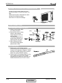
DLF DC Inverter Series
Indoor Units
Outdoor Units
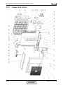
DLF 25 DCI
ONG3-25 DCI
DLF 35 DCI
ONG3-35 DCI
DLF 50 DCI
DCI 50
DLF 60 DCI
DCI 60
DLF 72 DCI
DCI 72Z
REFRIGERANT
R410A
SM DLF 1-A.1 GB
HEAT PUMP
AUGUST – 2008
CONTENT
LIST OF EFFECTIVE PAGES
LIST OF EFFECTIVE PAGES
Note: Changes in the pages are indicated by a “Revision#” in the footer of each effected page
(when none indicates no changes in the relevant page). All pages in the following list represent
effected/ non effected pages divided by chapters.
Dates of issue for original and changed pages are:
Original ....... 0 ........ November 2007
Total number of pages in this publication is 145 consisting of the following:
Page
No.
Revision
No. #
Page
No.
Revision
No. #
Page
No.
Revision
No. #
Title .......................1
A ...........................1
i .............................1
1-1 - 1-3 ................1
2-1 - 2-5 ................1
3-1 ........................1
4-1 - 4-3 ................1
5-1 - 5-25 ..............1
6-1 - 6-3 ................1
7-1 - 7-5 ................1
8-1 ........................1
9-1 - 9-3 ................1
10-1 ......................1
11-1 .......................1
12-1 ......................1
13-1-13-26 ............1
14-1-14-7 ..............1
15-1-15-13 ............1
16-1-16-50 ............1
•
Zero in this column indicates an original page.
* Due to constant improvements please note that the data on this service manual can be modified with out notice.
** Photos are not contractual.
A
CONTENT
SM DLF 1-A.1 GB
TABLE OF CONTENTS
Table of Contents
1.
INTRODUCTION ...................................................................................................1-1
2.
PRODUCT DATA SHEET ......................................................................................2-1
3.
RATING CONDITIONS ..........................................................................................3-1
4.
OUTLINE DIMENSIONS .......................................................................................4-1
5.
PERFORMANCE DATA & PRESSURE CURVES ................................................5-1
6.
AIRFLOW CURVES ..............................................................................................6-1
7.
SOUND LEVEL CHARACTERISTICS ..................................................................7-1
8.
ELECTRICAL DATA ..............................................................................................8-1
9.
WIRING DIAGRAMS .............................................................................................9-1
10. ELECTRICAL CONNECTIONS .............................................................................10-1
11.
REFRIGERATION DIAGRAMS .............................................................................11-1
12. TUBING CONNECTIONS......................................................................................12-1
13. CONTROL SYSTEM .............................................................................................13-1
14. TROUBLESHOOTING ..........................................................................................14-1
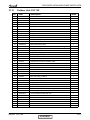
15. EXPLODED VIEWS AND SPARE PARTS LISTS .................................................15-1
16. APPENDIX A .........................................................................................................16-1
SM DLF 1-A.1 GB
i
INTRODUCTION
1.
INTRODUCTION
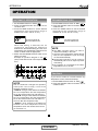
1.1
General
The new DLF DC INVERTER concealed split unit range comprises the RC (heat pump)
models as follow:
● DLF 25
● DLF 35
● DLF 50
● DLF 60
● DLF 72
Remote control compatibility
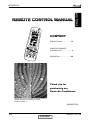
The DLF unit is compatible with remote controls RC3, RC4, RCW1, RCW2, and RC7.
Unlike standard units (fix RPM) that are selected according to their nominal capacity to
overcome the maximum required load; DC Inverter units can be selected to a smaller
nominal capacity range unit.
It made possible due to the ability of inverters to reach a much higher capacity level
(indicated as Maximum Capacity) which is around 115-130% of the nominal capacity.
1.2
Main Features
High level DC inverter system combined with concealed indoor units.
The system consists of high technology DC Brushless compressor, outdoor and indoor
fan motors.
The system adopts new ODP free refrigerant R410A and other environmental regulations
such as RoHS, WEEE, etc.
We believe this is the most suitable solution for residential and light commercial air
conditioning.
The indoor with only 200 mm height and together with the integrated water pump allows
best fit into very low ceiling space.
The units’ unique feature is the option of install the unit in horizontal or vertical position
without any additional work.
The unit low noise level (up to 25 DBA) fits perfectly for application as hotels, bed room
and small offices.
The DLF series benefits from the most advanced technological innovations, namely:
Variable cooling and heating capacity from 30% to 115% (of rated capacity)
High COP
Low noise levels in both indoors and outdoors
Extreme low silhouette, only 200mm.
Pre-charged system up to 30m
Tubing up to 50m length and 30m height difference
Networking connectivity
Dry contact output – Alarm
Ready for base heater and crank case heater installation including software support
HMI Display consists of 7-segments shows system diagnostics and setup (in some
models only)
Monitoring software (PC port for high level service)
Operating range cooling: From -10ºC to 46ºC outdoors
Operating range heating: From -15ºC to 24ºC outdoors
SM DLF 1-A.1 GB
CONTENT
1-1
INTRODUCTION
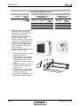
1.3
Indoor Unit
The indoor unit can fit easily to many types of residential and commercials applications.
It includes:
Water-pump drainage build-in.
Emergency Water-float to prevent over flow.
Horizontal/ Vertical installation build in.
2 options of return air location, on back of the unit or bellow the unit.
DC BL motor with maximum fan speed flexibility.
High technology plastic fan and fan housing.
Advanced electronic control box assembly with 1-meter cable to allow installation at
a more accessible area.
1.4
Filtration
The air filter can be located in the back side or in the bottom of the unit for easy access.
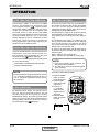
1.5
Control
The microprocessor indoor controller, and an infrared remote control, supplied as
standard, provides complete operating function and programming. For further details,
please refer to the Operation Manual, Appendix A.
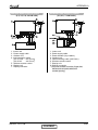
1.6
Outdoor Unit
The outdoor units can be installed as floor or wall mounted units by using a wall-supporting
bracket. The metal sheets are protected by anti- corrosion paintwork allowing long life
resistance. All outdoor units are pre-charged. For further information, please refer to the
Product Data Sheet, Chapter 2.
It includes:
● Compressor mounted in a soundproofed compartment :
Rotary – for DLF 25-35
Scroll – for DLF 50-60-72
● Improved 3- blades axial fans for noise reduction.
● Outdoor coil with hydrophilic fins for RC units optimised for operation with R 410A
refrigerant.
● Fan grill air outlet.
● Service valves” flare” type connection.
● Interconnecting wiring terminal block.
1.7
Tubing Connections
Flare type-interconnecting tubing to be produced on site.
For further details, please refer to the Installation Manual, Chapter 9.
1-2
CONTENT
SM DLF 1-A.1 GB
INTRODUCTION
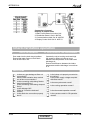
1.8
Accessories
RCW Wall Mounted Remote Control
The RCW remote control is mounted on the wall, and controls the unit either as an
infrared remote control or as a wired controller. The wired controller can control up to 10
Indoor units with the same program settings and adjustments.
For further details, please refer to the Technical Service Manual.
1.9
Inbox Documentation
Each unit includes its own installation and operation manuals.
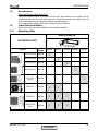
1.10
Matching Table
INDOOR UNITS
OUTDOOR UNITS
REFRIGER.
DLF 25
DCI 25 (ONG3)
R410A
√
DCI 35 (ONG3)
R410A
DCI 50 (ONG3)
R410A
DCI 60 (GC24)
R410A
DCI 72Z
R410A
MODEL
(GC30)
SM DLF 1-A.1 GB
DLF 35
DLF 50
DLF 60
DLF 72
√
√
√
√
DUO DCI
R410A
√
√
TRIO DCI
R410A
√
√
√
QUATTRO
DCI
R410A
√
√
√
CONTENT
1-3
PRODUCT DATA SHEET
2.
PRODUCT DATA SHEET
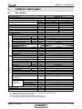
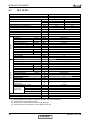
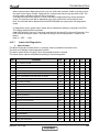
2.1
DLF 25 DCI
Model Indoor Unit
Model Outdoor Unit
Installation method of Pipe
Characteristics
DLF 25 DCI
ONG3-25 DCI
DUCTED
Capacity (1)
OUTDOOR
INDOOR
Power input (1)
EER (Cooling) or COP (Heating) (1)
Energy efficiency class
Power supply
Rated current
Starting current
Circuit breaker rating
Fan type & quantity
Fan speeds
H/ M/ L
Air flow (2)
H/ M/ L
External static pressure
Min-Max
Sound power level (3)
H/ M/ L
Sound pressure level (4)
H/ M/ L
Moisture removal
Condensate drain tube I.D
Dimensions
WxHxD
Weight
Package dimensions
WxHxD
Packaged weight
Units per pallet
Stacking height
Refrigerant control
Compressor type, model
Fan type & quantity
Air flow
H/L
Sound power level
H/L
Sound pressure level (4)
H/L
Dimensions
WxHxD
Weight
Package dimensions
WxHxD
Packaged weight
Units per pallet
Stacking height
Refrigerant type
Refrigerant charge (standard connecting
tubing length)
Additional charge per 1 meter
Liquid line
Connections
Suction line
between units
Max. tubing length
Max. height difference
Operation control type
Heating elements
Others
(1)
(2)
(3)
(4)
Units
Btu/hr
kW
kW
W/W
V/Ph/Hz
A
A
A
RPM
m³/hr
Pa
dB(A)
dB(A)
L/hr
mm
mm
kg
mm
kg
Units
Units
m³/hr
dB(A)
dB(A)
mm
kg
mm
kg
Units
Units
Cooling
Heating
8500 (4780-12280)
11600 (5120-17060)
2.5 (1.40-3.60)
3.4 (1.50-5.0)
0.625
0.87
4.0
3.9
A
A
220-240/1/50
2.7
3.6
10.5
16
Centrifugal & 2
920/810/740
620/560/490
0-30
50/47/44
29/26/23
0.5
19
750x630x200
20
885x695x226
23
14
7
Electronic Expansion Valve
DC Inverter single rotary
Axial & 1
1780
60
50
795x610x290
38
945x655x395
41
9
3
R410A
kg
1.1
g/m
In.
In.
m.
m.
No need
1/4”
3/8”
20
15
I.R Remote control
kW
Rating conditions in accordance to ISO 5151 and ISO 13253 (for ducted units).
Airflow without external static pressure.
Sound power in ducted units is measured at air discharge.
Sound pressure level measured at 1-meter distance from unit.
SM DLF 1-A.1 GB
CONTENT
2-1
PRODUCT DATA SHEET
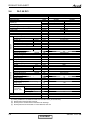
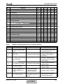
2.2
DLF 35 DCI
Model Indoor Unit
Model Outdoor Unit
Installation method of Pipe
Characteristics
Capacity (1)
OUTDOOR
INDOOR
Power input (1)
EER (Cooling) or COP (Heating) (1)
Energy efficiency class
Power supply
Rated current
Starting current
Circuit breaker rating
Fan type & quantity
Fan speeds
H/ M/ L
Air flow (2)
H/ M/ L
External static pressure
Min-Max
Sound power level (3)
H/ M/ L
Sound pressure level (4)
H/ M/ L
Moisture removal
Condensate drain tube I.D
Dimensions
WxHxD
Weight
Package dimensions
WxHxD
Packaged weight
Units per pallet
Stacking height
Refrigerant control
Compressor type, model
Fan type & quantity
Air flow
H/L
Sound power level
H/L
Sound pressure level (4)
H/L
Dimensions
WxHxD
Weight
Package dimensions
WxHxD
Packaged weight
Units per pallet
Stacking height
Refrigerant type
Refrigerant charge (standard connecting
tubing length)
Additional charge per 1 meter
Liquid line
Suction line
Connections
between units
Max. tubing length
Max. height difference
Operation control type
Heating elements
Others
(1)
(2)
(3)
(4)
2-2
DLF 35 DCI
ONG3-35 DCI
DUCTED
Units
Btu/hr
kW
kW
W/W
V/Ph/Hz
A
A
A
RPM
m³/hr
Pa
dB(A)
dB(A)
L/hr
mm
mm
kg
mm
kg
Units
Units
m³/hr
dB(A)
dB(A)
mm
kg
mm
kg
Units
Units
Cooling
Heating
11940 (4780-14670)
14670 (5100-19790)
3.5 (1.40-4.30)
4.3 (1.50-5.80)
0.95
1.16
3.67
3.62
A
A
220-240/1/50
3.67
4.8
10.5
16
Centrifugal & 2
980/860/730
650/580/490
0-30
53/49/45
31/27/24
1.0
19
200x750x630
20
885x695x226
23
14
7
Electronic Expansion Valve
DC Inverter single rotary
Axial & 1
1780
62
52
795x610x290
38
945x655x395
43
9
3
R410A
kg
1.2
g/m
In.
In.
m.
m.
No need
1/4”
3/8”
20
15
I.R Remote control
kW
Rating conditions in accordance to ISO 5151 and ISO 13253 (for ducted units).
Airflow without external static pressure.
Sound power in ducted units is measured at air discharge.
Sound pressure level measured at 1-meter distance from unit.
CONTENT
SM DLF 1-A.1 GB
PRODUCT DATA SHEET
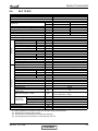
2.3
DLF 50 DCI
Model Indoor Unit
Model Outdoor Unit
Installation method of Pipe
Characteristics
Capacity (1)
OUTDOOR
INDOOR
Power input (1)
EER (Cooling) or COP (Heating) (1)
Energy efficiency class
Power supply
Rated current
Starting current
Circuit breaker rating
Fan type & quantity
Fan speeds
H/ M/ L
Air flow (2)
H/ M/ L
External static pressure
Min-Max
Sound power level (3)
H/ M/ L
Sound pressure level (4)
H/ M/ L
Moisture removal
Condensate drain tube I.D
Dimensions
WxHxD
Weight
Package dimensions
WxHxD
Packaged weight
Units per pallet
Stacking height
Refrigerant control
Compressor type, model
Fan type & quantity
Air flow
H/L
Sound power level
H/L
Sound pressure level (4)
H/L
Dimensions
WxHxD
Weight
Package dimensions
WxHxD
Packaged weight
Units per pallet
Stacking height
Refrigerant type
Refrigerant charge (standard connecting
tubing length)
Additional charge per 1 meter
Liquid line
Connections
Suction line
between units
Max. tubing length
Max. height difference
Operation control type
Heating elements
Others
(1)
(2)
(3)
(4)
DLF 50 DCI
DCI 50
DUCTED
Units
Btu/hr
kW
kW
W/W
V/Ph/Hz
A
A
A
RPM
m³/hr
Pa
dB(A)
dB(A)
L/hr
mm
mm
kg
mm
kg
Units
Units
m³/hr
dB(A)
dB(A)
mm
kg
mm
kg
Units
Units
Cooling
Heating
17060 (5120-20470)
20470 (5120-25930)
5.0 (1.50-6.00)
6.0 (1.50-7.60)
1.5
1.73
3.3
3.47
A
A
220-240/1/50
6.5
7.6
10.5
20
Centrifugal & 2
1100/980/860
710/600/540
0-40
54/51/48
35/32/29
1.5
19
750x630x200
21
885x695x226
24
14
7
Electronic Expansion Valve
Scroll, DC
Axial & 1
2160
63
53
795x610x290
39
945x655x395
43
9
3
R410A
kg
1.5
g/m
In.
In.
m.
m.
No need
1/4”
1/2”
30
15
I.R Remote control
kW
Rating conditions in accordance to ISO 5151 and ISO 13253 (for ducted units).
Airflow without external static pressure.
Sound power in ducted units is measured at air discharge.
Sound pressure level measured at 1-meter distance from unit.
SM DLF 1-A.1 GB
CONTENT
2-3
PRODUCT DATA SHEET
2.4
DLF 60 DCI
Model Indoor Unit
Model Outdoor Unit
Installation method of Pipe
Characteristics
Capacity (1)
OUTDOOR
INDOOR
Power input (1)
EER (Cooling) or COP (Heating) (1)
Energy efficiency class
Power supply
Rated current
Starting current
Circuit breaker rating
Fan type & quantity
Fan speeds
H/ M/ L
Air flow (2)
H/ M/ L
External static pressure
Min-Max
Sound power level (3)
H/ M/ L
Sound pressure level (4)
H/ M/ L
Moisture removal
Condensate drain tube I.D
Dimensions
WxHxD
Weight
Package dimensions
WxHxD
Packaged weight
Units per pallet
Stacking height
Refrigerant control
Compressor type, model
Fan type & quantity
Air flow
H/L
Sound power level
H/L
Sound pressure level (4)
H/L
Dimensions
WxHxD
Weight
Package dimensions
WxHxD
Packaged weight
Units per pallet
Stacking height
Refrigerant type
Refrigerant charge (standard connecting
tubing length)
Additional charge per 1 meter
Liquid line
Suction line
Connections
between units
Max. tubing length
Max. height difference
Operation control type
Heating elements
Others
(1)
(2)
(3)
(4)
2-4
DLF 60 DCI
DCI 60
DUCTED
Units
Btu/hr
kW
kW
W/W
V/Ph/Hz
A
A
A
RPM
m³/hr
Pa
dB(A)
dB(A)
L/hr
mm
mm
kg
mm
kg
Units
Units
m³/hr
dB(A)
dB(A)
mm
kg
mm
kg
Units
Units
Cooling
Heating
20800 (5120-22860)
22520 (5120-26950)
6.1 (1.50-6.70)
6.6 (1.50-7.90)
1.9
1.7
3.25
3.81
A
A
220-240/1/50
8.2
7.8
15
20
Centrifugal & 3
1170/1050/960
1100/950/880
0-40
59/55/53
38/34/32
1.7
19
1050x630x200
25
1185x695x226
28
14
7
Electronic Expansion Valve
Scroll
Axial & 1
2860
65
55
846x690x302
46
990x770x430
50
9
3
R410A
kg
1.65
g/m
In.
In.
m.
m.
No need
1/4”
1/2”
30
15
I.R Remote control
kW
Rating conditions in accordance to ISO 5151 and ISO 13253 (for ducted units).
Airflow without external static pressure.
Sound power in ducted units is measured at air discharge.
Sound pressure level measured at 1-meter distance from unit.
CONTENT
SM DLF 1-A.1 GB
PRODUCT DATA SHEET
2.5
DLF 72 DCI
Model Indoor Unit
Model Outdoor Unit
Installation method of Pipe
Characteristics
Capacity (1)
OUTDOOR
INDOOR
Power input (1)
EER (Cooling) or COP (Heating) (1)
Energy efficiency class
Power supply
Rated current
Starting current
Circuit breaker rating
Fan type & quantity
Fan speeds
H/ M/ L
Air flow (2)
H/ M/ L
External static pressure
Min-Max
Sound power level (3)
H/ M/ L
Sound pressure level (4)
H/ M/ L
Moisture removal
Condensate drain tube I.D
Dimensions
WxHxD
Weight
Package dimensions
WxHxD
Packaged weight
Units per pallet
Stacking height
Refrigerant control
Compressor type, model
Fan type & quantity
Air flow
H/L
Sound power level
H/L
Sound pressure level (4)
H/L
Dimensions
WxHxD
Weight
Package dimensions
WxHxD
Packaged weight
Units per pallet
Stacking height
Refrigerant type
Refrigerant charge (standard connecting
tubing length)
Additional charge per 1 meter
Connections
between units
Operation control type
Heating elements
Others
(1)
(2)
(3)
(4)
Liquid line
Suction line
Max. tubing length
Max. height difference
DLF 72 DCI
DCI 72Z
DUCTED
Units
Btu/hr
kW
kW
W/W
Cooling
Heating
23880 (5120-25600)
25420 (5120-30020)
7.0 (1.50-7.50)
7.45 (1.50-8.80)
2.1
2.1
3.4
3.68
A
A
220-240/1/50
9.3
9.3
15
20
Centrifugal & 3
1200/1050/980
1150/950/900
0-40
63/59/56
39/35/32
2.0
19
1050x630x200
25
1185x695x226
28
14
7
Electronic Expansion Valve
Twin rotary
Axial & 1
3600
66
56
950x835x412
65.5
1080x910x477
73
2
2
R410A
V/Ph/Hz
A
A
A
RPM
m³/hr
Pa
dB(A)
dB(A)
L/hr
mm
mm
kg
mm
kg
Units
Units
m³/hr
dB(A)
dB(A)
mm
kg
mm
kg
Units
Units
kg
g/m
In.
In.
m.
m.
2.3
7.5m<Length≤20m:+0g; 20m<Length≤30m:+300g;
30m<Length≤50m; +1500g
3/8”
5/8”
50
30
I.R Remote control
kW
Rating conditions in accordance to ISO 5151 and ISO 13253 (for ducted units).
Airflow without external static pressure.
Sound power in ducted units is measured at air discharge.
Sound pressure level measured at 1-meter distance from unit.
SM DLF 1-A.1 GB
CONTENT
2-5
RATING CONDITIONS
3.
RATING CONDITIONS
Standard conditions in accordance with ISO 5151 and ISO 13253 (for ducted units) and
EN 14511.
Cooling:
Indoor:
27oC DB 19oC WB
Outdoor: 35 oC DB
Heating:
Indoor:
20oC DB
Outdoor: 7oC DB 6oC WB
3.1
Operating Limits
Indoor
Cooling
Heating
Voltage
SM DLF 1-A.1 GB
Upper limit
Lower limit
Upper limit
Lower limit
1PH
CONTENT
Outdoor
32oC DB 23oC WB 46oC DB
21oC DB 15oC WB -10oC DB
24oC DB 18oC WB
27oC DB
20oC DB
-15oC DB -16oC WB
198 – 264V
3-1
OUTLINE DIMENSIONS
OUTLINE DIMENSIONS
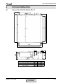
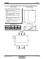
4.1
Indoor Unit: DLF 25, 35, 50, 60, 72
B
C
A
59
4.
565
21
160
200
59
Nominal Capacity
2.5 -5.0 kW
6.0-7.2 kW
SM DLF 1-A.1 GB
27
629 (640 With air filter)
A
B
C
750 696 790
1050 996 1090
CONTENT
4-1
OUTLINE DIMENSIONS
4.2
Outdoor Unit: DCI 25, 35, 50
4.3
Outdoor Unit: DCI 60
4-2
CONTENT
SM DLF 1-A.1 GB
OUTLINE DIMENSIONS
4.4
Outdoor Unit: DCI 72Z
SM DLF 1-A.1 GB
CONTENT
4-3
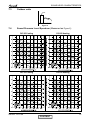
PERFORMANCE DATA & PRESSURE CURVES
5.
PERFORMANCE DATA & PRESSURE CURVES
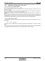
5.1
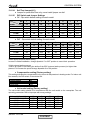
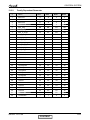
DLF 25 / ONG3-25 DCI
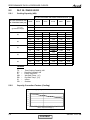
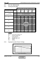
5.1.1
Cooling Capacity (kW)
ID COIL ENTERING AIR DB/WB TEMPERATURE [C0]
OD COIL ENTERING AIR
DB TEMPERATURE [CO]
DATA
-10 - 20
(protection range)
25
30
35
40
46
22/15
24/17
27/19
29/21
TC
80 - 110 % of nominal
SC
80 - 105 % of nominal
PI
25 - 50 % of nominal
32/23
TC
2.42
2.57
2.73
2.89
3.05
SC
2.02
2.06
2.10
2.14
2.18
PI
0.49
0.50
0.51
0.52
0.52
TC
2.30
2.46
2.62
2.77
2.93
SC
1.97
2.01
2.05
2.09
2.13
PI
0.54
0.55
0.56
0.57
0.58
TC
2.18
2.34
2.50
2.66
2.82
SC
1.92
1.96
2.00
2.04
2.08
PI
0.60
0.61
0.62
0.63
0.64
TC
2.07
2.23
2.38
2.54
2.70
SC
1.87
1.91
1.95
1.99
2.03
PI
0.66
0.67
0.68
0.69
0.70
TC
1.93
2.09
2.24
2.40
2.56
SC
1.81
1.85
1.89
1.93
1.97
PI
0.73
0.74
0.75
0.75
0.76
LEGEND
TC
SC
PI
WB
DB
ID
OD
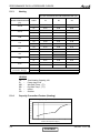
5.1.2
–
–
–
–
–
–
–
Total Cooling Capacity, kW
Sensible Capacity, kW
Power Input, kW
Wet Bulb Temp., (oC)
Dry Bulb Temp., (oC)
Indoor
Outdoor
Capacity Correction Factors (Cooling)
Cooling Capacity Ratio Vs.Outdoor Temperature
1.2
Capacity Factor
1.1
1.0
0.9
0.8
0.7
0.6
0.5
20
25
30
35
40
45
Outdoor Temperature DB [deg C]
SM DLF 1-A.1 GB
CONTENT
5-1
PERFORMANCE DATA & PRESSURE CURVES
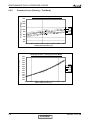
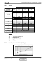
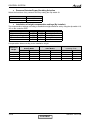
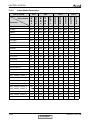
5.1.3
Heating
ID COIL ENTERING AIR DB TEMPERATURE [°C]
OD COIL ENTERING AIR
DB/WB TEMPERATURE
[°C]
-15/-16
-10/-12
-7/-8
-1/-2
2/1
7/6
10/9
15/12
DATA
15
20
25
TC
2.16
2.01
1.86
PI
0.52
0.58
0.63
TC
2.41
2.26
2.11
PI
0.63
0.68
0.74
TC
2.59
2.44
2.29
PI
0.71
0.76
0.82
TC
2.68
2.53
2.38
PI
0.78
0.83
0.88
TC
2.75
2.59
2.44
PI
0.82
0.87
0.92
TC
3.55
3.40
3.25
PI
0.82
0.87
0.92
TC
3.75
3.60
3.44
PI
0.87
0.92
0.97
TC
3.94
3.79
3.64
PI
0.91
0.97
1.02
15-24
TC
85 - 105 % of nominal
(Protection Range)
PI
80 - 120 % of nominal
LEGEND
TH
PI
WB
DB
ID
OD
5.1.4
–
–
–
–
–
–
Total Heating Capacity, kW
Power Input, kW
Wet Bulb Temp., (oC)
Dry Bulb Temp., (oC)
Indoor
Outdoor
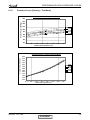
Capacity Correction Factors (Heating)
Heating Capacity Ratio Vs. Outdoor Temperature
1.2
Capacity Factor
1.1
1.0
0.9
0.8
0.7
0.6
0.5
-20
-15
-10
-5
0
5
10
15
Outdoor WB Temperature [deg C]
5-2
CONTENT
SM DLF 1-A.1 GB
PERFORMANCE DATA & PRESSURE CURVES
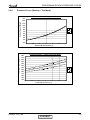
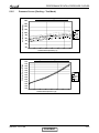
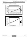
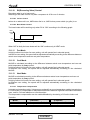
5.1.5
Pressure Curves (Cooling – Test Mode)
Suction Pressure - Cooling (Technician Mode)
1400
Suction Pressure [KPa(g)]
1300
1200
1100
32/23
29/21
27/19
24/17
22/15
1000
900
800
700
600
500
10
15
20
25
30
35
Outdoor DB Temperature [°C]
40
45
Discharge Pressure - Cooling (Technician Mode)
Discharge Pressure [KPa(g)]
4000
3750
3500
3250
3000
32/23
29/21
27/19
24/17
22/15
2750
2500
2250
2000
1750
1500
1250
1000
10
SM DLF 1-A.1 GB
15
20
25
30
35
Outdoor DB Temperature [°C]
CONTENT
40
45
5-3
PERFORMANCE DATA & PRESSURE CURVES
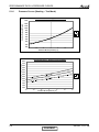
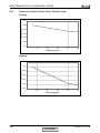
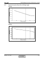
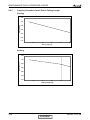
5.1.6
Pressure Curves (Heating – Test Mode)
Suction Pressure - Heating (Technician Mode)
1300
Suction Pressure [KPa(g)]
1200
1100
1000
900
15
20
25
800
700
600
500
400
300
200
-15
-10
-5
0
5
Outdoor WB Temperature [°C]
10
15
Discharge Pressure - Heating (Technician Mode)
4000
Discharge Pressure [KPa(g)]
3750
3500
3250
3000
2750
15
20
25
2500
2250
2000
1750
1500
1250
1000
-15
-10
-5
0
5
10
15
Outdoor WB Temperature [°C]
5-4
CONTENT
SM DLF 1-A.1 GB
PERFORMANCE DATA & PRESSURE CURVES
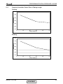
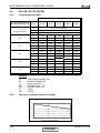
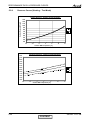
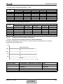
5.1.7
Capacity Correction Factor Due to Tubing Length
Cooling
1.05
Capacity Ratio
1.00
0.95
0.90
0.85
0.80
0.75
5
10
15
20
25
30
25
30
Tubing Lenght [m]
Heating
1.05
Capacity Ratio
1.00
0.95
0.90
0.85
0.80
0.75
5
10
15
20
Tubing Lenght [m]
SM DLF 1-A.1 GB
CONTENT
5-5
PERFORMANCE DATA & PRESSURE CURVES
5.2
DLF 35 / ONG3-35 DCI
5.2.1
Cooling Capacity (kW)
ID COIL ENTERING AIR DB/WB TEMPERATURE [C0]
OD COIL ENTERING AIR
DB TEMPERATURE [C0]
DATA
-10 - 20
(protection range)
25
30
35
40
46
22/15
24/17
27/19
29/21
TC
80 - 110 % of nominal
SC
80 - 105 % of nominal
PI
25 - 50 % of nominal
32/23
TC
3.38
3.60
3.83
4.05
4.27
SC
2.76
2.81
2.87
2.93
2.98
PI
0.75
0.76
0.78
0.79
0.80
TC
3.22
3.44
3.66
3.88
4.11
SC
2.69
2.74
2.80
2.86
2.91
PI
0.83
0.85
0.86
0.88
0.89
TC
3.06
3.28
3.50
3.72
3.94
SC
2.62
2.67
2.73
2.79
2.84
PI
0.92
0.94
0.95
0.96
0.98
TC
2.89
3.12
3.34
3.56
3.78
SC
2.55
2.60
2.66
2.72
2.77
PI
1.01
1.02
1.04
1.05
1.07
TC
2.70
2.92
3.14
3.36
3.58
SC
2.46
2.52
2.58
2.63
2.69
PI
1.11
1.13
1.14
1.16
1.17
LEGEND
TC
SC
PI
WB
DB
ID
OD
5.2.2
–
–
–
–
–
–
–
Total Cooling Capacity, kW
Sensible Capacity, kW
Power Input, kW
Wet Bulb Temp., (oC)
Dry Bulb Temp., (oC)
Indoor
Outdoor
Capacity Correction Factors (Cooling)
Cooling Capacity Ratio Vs.Outdoor Temperature
1.2
Capacity Factor
1.1
1.0
0.9
0.8
0.7
0.6
0.5
20
25
30
35
40
45
Outdoor Temperature DB [deg C]
5-6
CONTENT
SM DLF 1-A.1 GB
PERFORMANCE DATA & PRESSURE CURVES
5.2.3
Heating
ID COIL ENTERING AIR DB TEMPERATURE [°C]
OD COIL ENTERING
AIR DB/WB
TEMPERATURE [°C]
-15/-16
-10/-12
-7/-8
-1/-2
2/1
7/6
10/9
15/12
DATA
15
20
25
TC
2.67
2.49
2.30
PI
0.70
0.77
0.84
TC
2.98
2.79
2.60
PI
0.84
0.91
0.98
TC
3.20
3.02
2.83
PI
0.95
1.02
1.09
TC
3.32
3.13
2.94
PI
1.00
1.07
1.14
TC
3.39
3.20
3.02
PI
1.04
1.11
1.18
TC
4.39
4.20
4.01
PI
1.09
1.16
1.23
TC
4.63
4.44
4.26
PI
1.15
1.23
1.30
TC
4.87
4.68
4.50
PI
1.22
1.29
1.36
15-24
TC
85 - 105 % of nominal
(Protection Range)
PI
80 - 120 % of nominal
LEGEND
TH
PI
WB
DB
ID
OD
5.2.4
–
–
–
–
–
–
Total Heating Capacity, kW
Power Input, kW
Wet Bulb Temp., (oC)
Dry Bulb Temp., (oC)
Indoor
Outdoor
Capacity Correction Factors (Heating)
Heating Capacity Ratio Vs. Outdoor Temperature
1.2
Capacity Factor
1.1
1.0
0.9
0.8
0.7
0.6
0.5
-20
-15
-10
-5
0
5
10
15
Outdoor WB Temperature [deg C]
SM DLF 1-A.1 GB
CONTENT
5-7
PERFORMANCE DATA & PRESSURE CURVES
5.2.5
Pressure Curves (Cooling – Test Mode)
Suction Pressure - Cooling (Technician Mode)
1400
Suction Pressure [KPa(g)]
1300
1200
1100
32/23
29/21
27/19
24/17
22/15
1000
900
800
700
600
500
10
15
20
25
30
35
Outdoor DB Temperature [°C]
40
45
Discharge Pressure - Cooling (Technician Mode)
4000
Discharge Pressure [KPa(g)]
3750
3500
3250
3000
32/23
29/21
27/19
24/17
22/15
2750
2500
2250
2000
1750
1500
1250
1000
10
5-8
15
20
25
30
35
Outdoor DB Temperature [°C]
CONTENT
40
45
SM DLF 1-A.1 GB
PERFORMANCE DATA & PRESSURE CURVES
5.2.6
Pressure Curves (Heating – Test Mode)
Suction Pressure - Heating (Technician Mode)
1300
Suction Pressure [KPa(g)]
1200
1100
1000
900
15
20
25
800
700
600
500
400
300
200
-15
-10
-5
0
5
Outdoor WB Temperature [°C]
10
15
Discharge Pressure - Heating (Technician Mode)
Discharge Pressure [KPa(g)]
4000
3750
3500
3250
3000
2750
15
20
25
2500
2250
2000
1750
1500
1250
1000
-15
-10
-5
0
5
10
15
Outdoor WB Temperature [°C]
SM DLF 1-A.1 GB
CONTENT
5-9
PERFORMANCE DATA & PRESSURE CURVES
5.2.7
Capacity Correction Factor Due to Tubing Length
Cooling
1.05
Capacity Ratio
1.00
0.95
0.90
0.85
0.80
0.75
5
10
15
20
25
30
25
30
Tubing Lenght [m]
Heating
1.05
Capacity Ratio
1.00
0.95
0.90
0.85
0.80
0.75
5
10
15
20
Tubing Lenght [m]
5-10
CONTENT
SM DLF 1-A.1 GB
PERFORMANCE DATA & PRESSURE CURVES
5.3
DLF 50 / ONG3-50 DCI
5.3.1
Cooling Capacity (kW)
ID COIL ENTERING AIR DB/WB TEMPERATURE [C0]
OD COIL ENTERING AIR
DB TEMPERATURE [C0]
DATA
-10 - 20
(protection range)
30
35
40
46
24/17
27/19
29/21
TC
80 - 110 % of nominal
SC
80 - 105 % of nominal
PI
25 - 50 % of nominal
TC
25
22/15
4.83
5.15
5.47
5.78
32/23
6.10
SC
3.74
3.81
3.89
3.96
4.04
PI
1.18
1.20
1.22
1.25
1.27
TC
4.60
4.92
5.23
5.55
5.86
SC
3.64
3.72
3.79
3.87
3.95
PI
1.32
1.34
1.36
1.38
1.41
TC
4.37
4.68
5.00
5.32
5.63
SC
3.55
3.62
3.70
3.78
3.85
PI
1.46
1.48
1.50
1.52
1.55
TC
4.14
4.45
4.77
5.08
5.40
SC
3.45
3.53
3.61
3.68
3.76
PI
1.59
1.62
1.64
1.66
1.68
TC
3.86
4.17
4.49
4.80
5.12
SC
3.34
3.42
3.49
3.57
3.64
PI
1.76
1.78
1.80
1.83
1.85
LEGEND
TC
SC
PI
WB
DB
ID
OD
5.3.2
–
–
–
–
–
–
–
Total Cooling Capacity, kW
Sensible Capacity, kW
Power Input, kW
Wet Bulb Temp., (oC)
Dry Bulb Temp., (oC)
Indoor
Outdoor
Capacity Correction Factors (Cooling)
Cooling Capacity Ratio Vs.Outdoor Temperature
1.2
Capacity Factor
1.1
1.0
0.9
0.8
0.7
0.6
0.5
20
25
30
35
40
45
Outdoor Temperature DB [deg C]
SM DLF 1-A.1 GB
CONTENT
5-11
PERFORMANCE DATA & PRESSURE CURVES
5.3.3
Heating
ID COIL ENTERING AIR DB TEMPERATURE [°C]
OD COIL ENTERING
AIR DB/WB
TEMPERATURE [°C]
-15/-16
-10/-12
-7/-8
-1/-2
2/1
7/6
10/9
15/12
DATA
15
20
25
TC
3.88
3.61
3.34
PI
1.04
1.14
1.25
TC
4.32
4.05
3.78
PI
1.25
1.36
1.46
TC
4.65
4.38
4.11
PI
1.41
1.52
1.62
TC
4.82
4.54
4.27
PI
1.49
1.60
1.70
TC
4.93
4.65
4.38
PI
1.54
1.65
1.76
TC
6.37
6.00
5.83
PI
1.62
1.73
1.84
TC
6.72
6.45
6.18
PI
1.72
1.83
1.93
TC
7.07
6.80
6.53
PI
1.82
1.92
2.03
15-24
TC
85 - 105 % of nominal
(Protection Range)
PI
80 - 120 % of nominal
LEGEND
TH
PI
WB
DB
ID
OD
5.3.4
–
–
–
–
–
–
Total Heating Capacity, kW
Power Input, kW
Wet Bulb Temp., (oC)
Dry Bulb Temp., (oC)
Indoor
Outdoor
Capacity Correction Factors (Heating)
Heating Capacity Ratio Vs. Outdoor Temperature
1.2
Capacity Factor
1.1
1.0
0.9
0.8
0.7
0.6
0.5
-20
-15
-10
-5
0
5
10
15
Outdoor WB Temperature [deg C]
5-12
CONTENT
SM DLF 1-A.1 GB
PERFORMANCE DATA & PRESSURE CURVES
5.3.5
Pressure Curves (Cooling – Test Mode)
Suction Pressure - Cooling (Technician Mode)
1400
Suction Pressure [KPa(g)]
1300
1200
1100
32/23
29/21
27/19
24/17
22/15
1000
900
800
700
600
500
10
15
20
25
30
35
Outdoor DB Temperature [°C]
40
45
Discharge Pressure - Cooling (Technician Mode)
Discharge Pressure [KPa(g)]
4000
3750
3500
3250
3000
32/23
29/21
27/19
24/17
22/15
2750
2500
2250
2000
1750
1500
1250
1000
10
15
20
25
30
35
40
45
Outdoor DB Temperature [°C]
SM DLF 1-A.1 GB
CONTENT
5-13
PERFORMANCE DATA & PRESSURE CURVES
5.3.6
Pressure Curves (Heating – Test Mode)
Suction Pressure - Heating (Technician Mode)
1300
Suction Pressure [KPa(g)]
1200
1100
1000
900
15
20
25
800
700
600
500
400
300
200
-15
-10
-5
0
5
Outdoor WB Temperature [°C]
10
15
Discharge Pressure - Heating (Technician Mode)
Discharge Pressure [KPa(g)]
4000
3750
3500
3250
3000
2750
15
20
25
2500
2250
2000
1750
1500
1250
1000
-15
-10
-5
0
5
10
15
Outdoor WB Temperature [°C]
5-14
CONTENT
SM DLF 1-A.1 GB
PERFORMANCE DATA & PRESSURE CURVES
5.3.7
Capacity Correction Factor Due to Tubing Length
Cooling
1.05
Capacity Ratio
1.00
0.95
0.90
0.85
0.80
0.75
5
10
15
20
25
30
25
30
Tubing Lenght [m]
Heating
1.05
Capacity Ratio
1.00
0.95
0.90
0.85
0.80
0.75
5
10
15
20
Tubing Lenght [m]
SM DLF 1-A.1 GB
CONTENT
5-15
PERFORMANCE DATA & PRESSURE CURVES
5.4
DLF 60 / DCI 60 (GC24)
5.4.1
Cooling Capacity (kW)
ID COIL ENTERING AIR DB/WB TEMPERATURE [C0]
OD COIL ENTERING AIR
DB TEMPERATURE [C0]
DATA
-10 - 20
(protection range)
25
30
35
40
46
22/15
24/17
27/19
29/21
TC
80 - 110 % of nominal
SC
80 - 105 % of nominal
PI
25 - 50 % of nominal
32/23
TC
5.80
6.18
6.56
6.94
7.32
SC
4.73
4.82
4.92
5.02
5.11
PI
1.48
1.51
1.53
1.56
1.59
TC
5.52
5.90
6.28
6.66
7.04
SC
4.61
4.70
4.80
4.90
4.99
PI
1.65
1.68
1.71
1.74
1.76
TC
5.24
5.62
6.10
6.38
6.76
SC
4.49
4.58
4.68
4.78
4.87
PI
1.82
1.85
1.88
1.91
1.94
TC
4.96
5.34
5.72
6.10
6.48
SC
4.37
4.46
4.56
4.66
4.75
PI
2.00
2.02
2.05
2.08
2.11
TC
4.63
5.01
5.39
5.77
6.14
SC
4.22
4.32
4.42
4.51
4.61
PI
2.20
2.23
2.26
2.29
2.32
LEGEND
TC
SC
PI
WB
DB
ID
OD
5.4.2
–
–
–
–
–
–
–
Total Cooling Capacity, kW
Sensible Capacity, kW
Power Input, kW
Wet Bulb Temp., (oC)
Dry Bulb Temp., (oC)
Indoor
Outdoor
Capacity Correction Factors (Cooling)
Cooling Capacity Ratio Vs.Outdoor Temperature
1.2
Capacity Factor
1.1
1.0
0.9
0.8
0.7
0.6
0.5
20
25
30
35
40
45
Outdoor Temperature DB [deg C]
5-16
CONTENT
SM DLF 1-A.1 GB
PERFORMANCE DATA & PRESSURE CURVES
5.4.3
Heating
ID COIL ENTERING AIR DB TEMPERATURE [°C]
OD COIL ENTERING
AIR DB/WB
TEMPERATURE [°C]
-15/-16
-10/-12
-7/-8
-1/-2
2/1
7/6
10/9
15/12
DATA
15
20
25
TC
4.20
3.91
3.61
PI
1.04
1.14
1.26
TC
4.68
4.38
4.09
PI
1.25
1.36
1.46
TC
5.03
4.74
4.45
PI
1.41
1.52
1.62
TC
5.21
4.92
4.62
PI
1.49
1.60
1.70
TC
5.33
5.04
4.74
PI
1.54
1.65
1.76
TC
6.89
6.60
6.31
PI
1.62
1.73
1.84
TC
7.27
6.98
6.69
PI
1.72
1.83
1.93
TC
7.65
7.36
7.07
PI
1.82
1.92
2.03
15-24
TC
85 - 105 % of nominal
(Protection Range)
PI
80 - 120 % of nominal
LEGEND
TH
PI
WB
DB
ID
OD
5.4.4
–
–
–
–
–
–
Total Heating Capacity, kW
Power Input, kW
Wet Bulb Temp., (oC)
Dry Bulb Temp., (oC)
Indoor
Outdoor
Capacity Correction Factors (Heating)
Heating Capacity Ratio Vs. Outdoor Temperature
1.2
Capacity Factor
1.1
1.0
0.9
0.8
0.7
0.6
0.5
-20
-15
-10
-5
0
5
10
15
Outdoor WB Temperature [deg C]
SM DLF 1-A.1 GB
CONTENT
5-17
PERFORMANCE DATA & PRESSURE CURVES
5.4.5
Pressure Curves (Cooling – Test Mode)
Suction Pressure - Cooling (Technician Mode)
1400
Suction Pressure [KPa(g)]
1300
1200
1100
32/23
29/21
27/19
24/17
22/15
1000
900
800
700
600
500
10
15
20
25
30
35
Outdoor DB Temperature [°C]
40
45
Discharge Pressure - Cooling (Technician Mode)
Discharge Pressure [KPa(g)]
4000
3750
3500
3250
3000
32/23
29/21
27/19
24/17
22/15
2750
2500
2250
2000
1750
1500
1250
1000
10
15
20
25
30
35
40
45
Outdoor DB Temperature [°C]
5-18
CONTENT
SM DLF 1-A.1 GB
PERFORMANCE DATA & PRESSURE CURVES
5.4.6
Pressure Curves (Heating – Test Mode)
Suction Pressure - Heating (Technician Mode)
1300
Suction Pressure [KPa(g)]
1200
1100
1000
900
15
20
25
800
700
600
500
400
300
200
-15
-10
-5
0
5
Outdoor WB Temperature [°C]
10
15
Discharge Pressure - Cooling (Technician Mode)
Discharge Pressure [KPa(g)]
4000
3750
3500
3250
3000
32/23
29/21
27/19
24/17
22/15
2750
2500
2250
2000
1750
1500
1250
1000
10
15
20
25
30
35
40
45
Outdoor DB Temperature [°C]
SM DLF 1-A.1 GB
CONTENT
5-19
PERFORMANCE DATA & PRESSURE CURVES
5.4.7
Capacity Correction Factor Due to Tubing Length
Cooling
1.05
Capacity Ratio
1.00
0.95
0.90
0.85
0.80
0.75
5
10
15
20
25
30
Tubing Lenght [m]
Heating
1.05
Capacity Ratio
1.00
0.95
0.90
0.85
0.80
0.75
5
10
15
20
25
30
Tubing Lenght [m]
5-20
CONTENT
SM DLF 1-A.1 GB
PERFORMANCE DATA & PRESSURE CURVES
5.5
DLF 72 / DCI 72Z
5.5.1
Cooling Capacity (kW)
ID COIL ENTERING AIR DB/WB TEMPERATURE [C0]
OD COIL ENTERING AIR
DB TEMPERATURE [C0]
DATA
-10 - 20
(protection range)
25
30
35
40
46
22/15
24/17
27/19
29/21
TC
80 - 110 % of nominal
SC
80 - 105 % of nominal
PI
25 - 50 % of nominal
32/23
TC
6.77
7.21
7.65
8.09
8.54
SC
5.51
5.63
5.74
5.85
5.96
PI
1.61
1.64
1.67
1.70
1.73
TC
6.44
6.88
7.33
7.77
8.21
SC
5.37
5.49
5.60
5.71
5.82
PI
1.80
1.83
1.86
1.89
1.92
TC
6.12
6.56
7.00
7.44
7.88
SC
5.24
5.35
5.46
5.57
5.68
PI
1.99
2.02
2.05
2.08
2.11
TC
5.79
6.23
6.67
7.12
7.56
SC
5.10
5.21
5.32
5.43
5.55
PI
2.18
2.21
2.24
2.27
2.30
TC
5.40
5.84
6.28
6.73
7.17
SC
4.93
5.04
5.15
5.27
5.38
PI
2.40
2.43
2.46
2.50
2.53
LEGEND
TC
SC
PI
WB
DB
ID
OD
5.5.2
–
–
–
–
–
–
–
Total Cooling Capacity, kW
Sensible Capacity, kW
Power Input, kW
Wet Bulb Temp., (oC)
Dry Bulb Temp., (oC)
Indoor
Outdoor
Capacity Correction Factors (Cooling)
Cooling Capacity Ratio Vs.Outdoor Temperature
1.2
Capacity Factor
1.1
1.0
0.9
0.8
0.7
0.6
0.5
20
25
30
35
40
45
Outdoor Temperature DB [deg C]
SM DLF 1-A.1 GB
CONTENT
5-21
PERFORMANCE DATA & PRESSURE CURVES
5.5.3
Heating
ID COIL ENTERING AIR DB TEMPERATURE [°C]
OD COIL ENTERING
AIR DB/WB
TEMPERATURE [°C]
-15/-16
-10/-12
-7/-8
-1/-2
2/1
7/6
10/9
15/12
DATA
15
20
25
TC
7.74
4.41
4.08
PI
1.21
1.34
1.46
TC
5.28
4.95
4.62
PI
1.46
1.58
1.71
TC
5.68
5.35
5.02
PI
1.65
1.77
1.89
TC
5.88
5.55
5.22
PI
1.74
1.86
1.99
TC
6.02
5.68
5.35
PI
1.80
1.93
2.05
TC
7.78
7.45
7.12
PI
1.90
2.02
2.14
TC
8.21
7.88
7.55
PI
2.01
2.13
2.26
TC
8.64
8.31
7.98
PI
2.12
2.25
2.37
15-24
TC
85 - 105 % of nominal
(Protection Range)
PI
80 - 120 % of nominal
LEGEND
TH
PI
WB
DB
ID
OD
5.5.4
–
–
–
–
–
–
Total Heating Capacity, kW
Power Input, kW
Wet Bulb Temp., (oC)
Dry Bulb Temp., (oC)
Indoor
Outdoor
Capacity Correction Factors (Heating)
Heating Capacity Ratio Vs. Outdoor Temperature
1.2
Capacity Factor
1.1
1.0
0.9
0.8
0.7
0.6
0.5
-20
-15
-10
-5
0
5
10
15
Outdoor WB Temperature [deg C]
5-22
CONTENT
SM DLF 1-A.1 GB
PERFORMANCE DATA & PRESSURE CURVES
5.5.5
Pressure Curves (Cooling – Test Mode)
Suction Pressure - Cooling (Technician Mode)
1400
Suction Pressure [KPa(g)]
1300
1200
1100
32/23
29/21
27/19
24/17
22/15
1000
900
800
700
600
500
10
15
20
25
30
35
Outdoor DB Temperature [°C]
40
45
Discharge Pressure - Cooling (Technician Mode)
Discharge Pressure [KPa(g)]
4000
3750
3500
3250
3000
2750
32/23
29/21
27/19
24/17
22/15
2500
2250
2000
1750
1500
1250
1000
10
15
20
25
30
35
40
45
Outdoor DB Temperature [°C]
SM DLF 1-A.1 GB
CONTENT
5-23
PERFORMANCE DATA & PRESSURE CURVES
5.5.6
Pressure Curves (Heating – Test Mode)
Suction Pressure - Heating (Technician Mode)
1300
Suction Pressure [KPa(g)]
1200
1100
1000
900
15
20
25
800
700
600
500
400
300
200
-15
-10
-5
0
5
Outdoor WB Temperature [°C]
10
15
Discharge Pressure - Heating (Technician Mode)
Discharge Pressure [KPa(g)]
4000
3750
3500
3250
3000
2750
15
20
25
2500
2250
2000
1750
1500
1250
1000
-15
-10
-5
0
5
10
15
Outdoor WB Temperature [°C]
5-24
CONTENT
SM DLF 1-A.1 GB
PERFORMANCE DATA & PRESSURE CURVES
5.5.7
Capacity Correction Factor Due to Tubing Length
Cooling
1.05
Capacity Ratio
1.00
0.95
0.90
0.85
0.80
0.75
0
10
20
30
40
50
40
50
Tubing Lenght [m]
Heating
1.05
Capacity Ratio
1.00
0.95
0.90
0.85
0.80
0.75
0
* Pre-charged to 30m.
SM DLF 1-A.1 GB
10
20
30
Tubing Lenght [m]
CONTENT
5-25
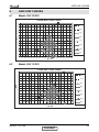
AIRFLOW CURVES
6.
AIRFLOW CURVES
6.1
Model: DLF 25 DCI
2.5KW AIR FLOW CHART
48
10PA
44
40
30PA
36
High
32
Med
ESP
28
24
Low
20
SHigh
16
12
SMed
8
Slow
4
0
0
50
100 150 200 250 300 350 400 450 500 550 600 650 700 750 800 850 900
M ³ /HR
6.2
Model: DLF 35 DCI
3.5KW AIR FLOW CHART
48
44
10PA
40
30PA
36
32
High
ESP
28
Med
24
20
Low
16
SHigh
12
8
SMed
4
Slow
0
0
50
100 150 200 250 300 350 400 450 500 550 600 650 700 750 800 850 900
M³ /HR
SM DLF 1-A.1 GB
CONTENT
6-1
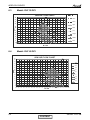
AIRFLOW CURVES
6.3
Model: DLF 50 DCI
5KW AIR FLOW CHART
10PA
48
20Pa
44
40PA
40
36
High
32
Med
ESP
28
24
Low
20
SHigh
16
12
SMed
8
4
Slow
0
0
50 100 150 200 250 300 350 400 450 500 550 600 650 700 750 800 850 900
M³ /HR
6.4
Model: DLF 60 DCI
6KW AIR FLOW CHART
60
56
52
10PA
48
44
20PA
40
40PA
36
ESP
High
32
Med
28
Low
24
20
SHigh
16
SMed
12
Slow
8
4
0
200
250
300
350
400
450
500
550
600
650
700
750
800
850
900
950 1000 1050 1100 1150 1200
M³ /HR
6-2
CONTENT
SM DLF 1-A.1 GB
AIRFLOW CURVES
6.5
Model: DLF 72 DCI
7.2KW AIR FLOW CHART
60
56
52
48
10PA
44
20PA
40
40PA
36
ESP
High
32
28
Med
24
Low
20
SHigh
16
12
SMed
8
Slow
4
0
300
350
400
450
500
550
600
650
700
750
800
850
900
950
1000 1050 1100 1150 1200 1250 1300
M³ /HR
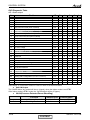
6.6
DLF UNITS RANGE AIR FLOW CORRECTION FACTORS
(at nominal rating conditions — Test mode).
Cooling
Heating
TC
SC
PI
PI
TC
60%
0.88
0.78
0.95
1.07
0.90
Air Flow Rate [% of nominal]
70%
80%
90%
0.91
0.94
0.97
0.84
0.89
0.95
0.97
0.98
0.99
1.05
1.03
1.02
0.92
0.95
0.97
100%
1
1
1
1
1
* Permissible Air flow Rate - according to model Air Flow Curves
SM DLF 1-A.1 GB
CONTENT
6-3
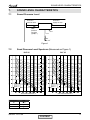
SOUND LEVEL CHARACTERISTICS
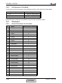
7.
SOUND LEVEL CHARACTERISTICS
7.1
Sound Pressure Level
2m duct in
supply air area
2m duct in
return air area
static
pressure
test point
(2(AB)1/2 )
Unit
1.4m
Mic.
Figure 1
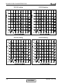
7.2
Soud Pressure Level Spectrum (Measured as Figure 1)
DLF 35
NC-70
NC-60
NC-50
NC-40
NC-30
APPROXIMATE
THRESHOLD OF
HEARING FOR
CONTINUOUS
NOISE
NC-20
OCTAVE BAND SOUND PRESSURE LEVEL, dB re 0.002 MICRO BAR
OCTAVE BAND SOUND PRESSURE LEVEL, dB re 0.002 MICRO BAR
DLF 25
NC-70
NC-60
NC-50
NC-40
NC-30
APPROXIMATE
THRESHOLD OF
HEARING FOR
CONTINUOUS
NOISE
NC-20
NC-10
BAND CENTER FREQUENCIES, Hz
FAN SPEED
NC-10
BAND CENTER FREQUENCIES, Hz
LINE
HI
ME
LO
SM DLF 1-A.1 GB
CONTENT
7-1
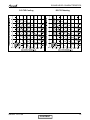
SOUND LEVEL CHARACTERISTICS
DLF 60
NC-70
NC-60
NC-50
NC-40
NC-30
APPROXIMATE
THRESHOLD OF
HEARING FOR
CONTINUOUS
NOISE
NC-20
NC-10
OCTAVE BAND SOUND PRESSURE LEVEL, dB re 0.002 MICRO BAR
OCTAVE BAND SOUND PRESSURE LEVEL, dB re 0.002 MICRO BAR
DLF 50
NC-70
NC-60
NC-50
NC-40
NC-30
APPROXIMATE
THRESHOLD OF
HEARING FOR
CONTINUOUS
NOISE
NC-20
BAND CENTER FREQUENCIES, Hz
BAND CENTER FREQUENCIES, Hz
OCTAVE BAND SOUND PRESSURE LEVEL, dB re 0.002 MICRO BAR
DLF 72
NC-70
NC-60
NC-50
NC-40
NC-30
APPROXIMATE
THRESHOLD OF
HEARING FOR
CONTINUOUS
NOISE
NC-20
BAND CENTER FREQUENCIES, Hz
FAN SPEED
LINE
HI
ME
LO
7-2
CONTENT
SM DLF 1-A.1 GB
SOUND LEVEL CHARACTERISTICS
7.3
Outdoor units
Unit
1m
Mic.
Ground
Figure 2
7.4
Sound Pressure Level Spectrum (Measured as Figure 2)
DCI 25 Cooling
DCI 25 Heating
DCI 35 Cooling
DCI 35 Heating
SM DLF 1-A.1 GB
CONTENT
7-3
SOUND LEVEL CHARACTERISTICS
7-4
DCI 50 Cooling
DCI 50 Heating
DCI 60 Cooling
DCI 60 Heating
CONTENT
SM DLF 1-A.1 GB
SOUND LEVEL CHARACTERISTICS
DCI 72Z Cooling
SM DLF 1-A.1 GB
DCI 72Z Heating
CONTENT
7-5
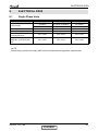
ELECTRICAL DATA
8.
ELECTRICAL DATA
8.1
Single Phase Units
MODEL
DLF 25-35
DLF 50-60
DLF 72
To Indoor
To Indoor or Outdoor
To Outdoor
1PH – 230V – 50 Hz
1PH – 230V – 50 Hz
1PH – 230V – 50 Hz
Max Current, A
10.5
15
15
Circuit Breaker
16
20
20
3 X 1.5 mm2
3 X 2.5 mm2
3 X 2.5 mm2
4 X 1.5 mm2
4 X 2.5 mm2
4 X 2.5 mm2
Power Supply
Power Supply Wiring No. X
Cross Section mm2
Interconnecting Cable RC
Model No. X Cross Section
mm2
NOTE:
Power wiring cord should comply with local lows and electrical regulations requirements.
SM DLF 1-A.1 GB
CONTENT
8-1
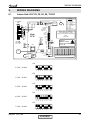
WIRING DIAGRAMS
9.
WIRING DIAGRAMS
9.1
Indoor Unit: DLF 25, 35, 50, 60, 72 DCI
Legend
To Outdoor
unit
EARTH L
WP
N COM
Fresh air
Water pump
TB
RED C/5
Connection to
Display
Display board
RED
BLU
N/3
BLU
BRN
L/4
BRN
16 pins display
connector
IR-S disable
jumper 15
Y/G
Y/G
Power supply (by installer):
1PH~220-230VAC / 50Hz
Cable between indoor and outdoor
units:
4x2.5mm²
To RC-W
uBMS
Y/G
BRN
L
BLU
N
ECC - External chock coil
DP - DIP switch
DSP - Display PCB
FM - Fan motor
MGP - Main ground point
PCB - Controller
SW - Water level switch
TB - Terminal board
WP - Water pump
BLU - Blue
BRN - Brown
RED - Red
Y/G - Yellow/green
Main
PCB
MGP
GND/12V +
-
Clock
Test jumper
230V ~50Hz
FM
On
ON
12345678
}
Power supply
Alarm
Water
level
Danger!!!
High DC voltage!
SW
Do not touch 1 minute after
Power off.
Mega
tool
DP
RAT
ECC
ICTE
FAN
ON
7
Horizontal
ICT sensor
RAT sensor
2.5 Kw
3.5 Kw
5.0 Kw
6.0 Kw
7.2 Kw
1
ON
ON
ON
ON
ON
2
OFF
OFF
OFF
ON
ON
3
4
OFF ON
OFF OFF
OFF ON
OFF OFF
OFF ON
5
OFF
ON
ON
OFF
OFF
6
OFF
OFF
OFF
OFF
OFF
7*
ON
ON
ON
ON
ON
8
OFF
OFF
OFF
OFF
OFF
* This is the setting for the water level/water pump activation.
For vertical installation jumper shall be OFF.
7
Vertical
Dip switch setting
ICT
Flash programming
CAT. No. 418720/02
ON
2.5 kW - 418960
1 2 3 4 5 6 7 8
ON
3.5 kW - 418961
1 2 3 4 5 6 7 8
ON
5.0 kW - 418962
1 2 3 4 5 6 7 8
ON
6.0 kW - 418963
1 2 3 4 5 6 7 8
ON
7.2 kW - 418964
1 2 3 4 5 6 7 8
SM DLF 1-A.1 GB
CONTENT
9-1
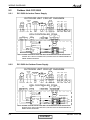
WIRING DIAGRAMS
9.2
Outdoor Unit: DCI 50/60
9.2.1
DCI 50/60 for Indoor Power Supply
OUTDOOR UNIT CIRCUIT DIAGRAM
OCT CTT
1 2
1 2
1 2
1 2
P2
P19
P20
P8
BLUE
YEL
ORG
1 2
P1
P4
BLK
1 2
RED
1 2 3 4 5 6
P14
P13
OAT
VSP
FG
BLUE
WHITE
BLK
RED
BRN
U V W
P3 P9 P11
OFAN
BASE
HEATER
(OPTIONAL)
GND
VCC
REVERSE
VALVE
COMP
VDC
CHOKE
COIL
P16 P17 P18 P21P22
ODU CONTROLLER PCBA
P17
P9
1 2 3 4 5 6
P12
EARTH
L N COM N-COM
P7
6 5 4 3 2 1
Y/G
Y/G
EEV
EMI FILTER PCBA
EARTH
EARTH
NCOM EARTH
COM
COM
RED
BLUE
BROWN
N-F
L
L-F
N
To
IDU
5/C
FERRITE CORE
4/L
N
FERRITE CORE
NOTE: WIRING SCHEME WITHIN DASHED LINE BORDERS ARE RELEVANT FOR
SINGLE SPLIT APPLICATIONS ONLY,FOR MULTI SPLIT WIRING REFER TO
MSMP WIRING DIAGRAM.
9.2.2
DCI 50/60 for Outdoor Power Supply
OUTDOOR UNIT CIRCUIT DIAGRAM
VSP
FG
BLUE
P14
BLUE
YEL
1 2
P1
P4
BLK
ORG
1 2
P13
OAT OCT CTT
1 2 3 4 5 6
RED
U V W
P3 P9 P11
WHITE
BLK
R ED
BRN
COMP
OFAN
BASE
HEATER
(OPTIONAL)
GND
VCC
REVERSE
VALVE
VD C
CHOKE
COIL
P16 P17 P18 P21P22
1 2
1 2
1 2
1 2
P2
P19
P20
P8
ODU CONTROLLER PCBA
P17
L N COM N-COM
P9
1 2 3 4 5 6
P12
EARTH
P7
6 5 4 3 2 1
Y/G
Y/G
EEV
EMI FILTER PCBA
POWER SUPPLY
EARTH
EARTH
RED
BLUE
BROWN
NCOM EARTH
COM
COM
N-F
L
L-F
N
5/C
FERRITE CORE
FERRITE CORE
4/L
To
IDU
N
NOTE: WIRING SCHEME WITHIN DASHED LINE BORDERS ARE RELEVANT FOR
SINGLE SPLIT APPLICATIONS ONLY,FOR MULTI SPLIT WIRING REFER TO
MSMP WIRING DIAGRAM.
9-2
CONTENT
SM DLF 1-A.1 GB
WIRING DIAGRAMS
Outdoor Unit: DCI 72Z
CHOKE
COIL REVERSE BASE
HEATER
U V W P13
P3 P9 P11
VALVE
BLUE
OFAN
(OPTIONAL)
1 2 3 4 5 6
1 2
P4
P14
1 2
P1
1 2 1 2 1 2 1 2 1 2
P19 P20 P2
P8 P5
1
P6
ODU CONTROLLER PCBA
P10
L N COM N-COM
P7
6 5 4 3 2 1
JP9
1 2 3 4 5 6
P12
EARTH
Y/G
FERRITE
CORE
OCT CTT OAT OMT HST
EEV
AC MAINS
EMI FILTER PCBA
EARTH
EARTH
BLACK
RED
BLUE
BROWN
SM DLF 1-A.1 GB
NCOM
COM
N-F
L-F
COM
N
L
L
FUSE
N
RED
BROWN
BLUE
RED
BROWN
BLUE
L N C L N
BLK
BRN
RED
COMP
WHITE
9.2.3
TO
IDU
FERRITE CORE
CONTENT
9-3
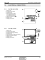
ELECTRICAL CONNECTIONS
10.
ELECTRICAL CONNECTIONS
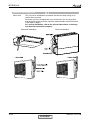
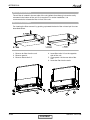
10.1
DLF 25, 35, 50 1PH
1
1. Indoor Unit
2. Power Supply Cable
3. Outdoor Unit
4. Interconnecting Cable:
2.5-3.5KW (4x1.5mm2)
5.0-6.0KW (4x2.5mm2)
5. Wireless Remote Control
6. Display Unit
7. Display Connector
7
6
N/3 L/4 C/5
5
2
220/240V~50Hz
4
3
10.2
8
DLF 60, 72 1PH
1
1. Indoor Unit
2. Power Supply Cable
3. Power breaker (by installer)
4. Outdoor Unit
5. Interconnecting Cable (4x2.5mm2)
6. Wireless Remote Control
7. Display Unit
8. Display Connector
7
6
2
3
220/240V~50Hz
5
4
SM DLF 1-A.1 GB
CONTENT
10-1
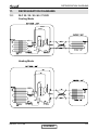
REFRIGERATION DIAGRAMS
11.
REFRIGERATION DIAGRAMS
11.1
DLF 25 / 35 / 50 / 60 / 72 DCI
Cooling Mode
EEV
Heating Mode
EEV
SM DLF 1-A.1 GB
CONTENT
11-1
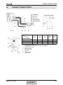
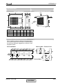
TUBING CONNECTIONS
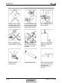
12.
TUBING CONNECTIONS
TUBE (Inch)
¼”
⅜”
½”
⅝”
¾”
15-18
13-20
11-13
40-45
13-20
11-13
60-65
18-25
11-13
70-75
18-25
11-13
80-85
40-50
11-13
TORQUE (Nm)
Flare Nuts
Valve Cap
Service Port Cap
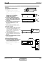
1.
2.
3.
4.
5.
6.
7.
8.
SM DLF 1-A.1 GB
Valve Protection Cap-end
Refrigerant Valve Port (use Allen wrench to open/close)
Valve Protection Cap
Refrigerant Valve
Service Port Cap
Flare Nut
Unit Back Side
Copper Tube
CONTENT
12-1
CONTROL SYSTEM
13.
CONTROL SYSTEM
13.1
General Functions and Operating RulesThe DCI software is fully
parametric.
All the model dependent parameters are shown in Blue color and with Italic style [parameter].
The parameters values are given in the last section of this control logic chapter of the service manual.
13.1.1
System Operation Concept
The control function is divided between indoor and outdoor unit controllers. Indoor unit is the system
‘Master’, requesting the outdoor unit for cooling/heating capacity supply. The outdoor unit is the
system ‘Slave’ and it must supply the required capacity unless it enters into a protection mode
avoiding it from supplying the requested capacity.
The capacity request is transferred via indoor to outdoor communication, and is represented by a
parameter called ‘NLOAD’. NLOAD is an integer number with values between 0 and 127, and it
represents the heat or cool load felt by the indoor unit.
13.1.2
13.1.2.1
Compressor Frequency Control
NLOAD setting
The NLOAD setting is done by the indoor unit controller, based on a PI control scheme.
The actual NLOAD to be sent to the outdoor unit controller is based on the preliminary LOAD
calculation, the indoor fan speed, and the power shedding function.
NLOAD limits as a function of indoor fan speed:
Indoor Fan Speed Maximum NLOAD Cooling Maximum NLOAD Heating
Indoor Fan Speed
Low
Medium
High
Turbo
Auto
Maximum NLOAD Cooling
MaxNLOADIF1C
MaxNLOADIF2C
MaxNLOADIF3C
MaxNLOADIF4C
MaxNLOADIF5C
Maximum NLOAD Heating
MaxNLOADIF1H
MaxNLOADIF2H
MaxNLOADIF3H
MaxNLOADIF4H
MaxNLOADIF5H
NLOAD limits as a function of power shedding:
Mode
Cooling
Heating
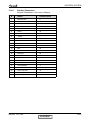
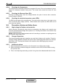
13.1.3
13.1.3.1
Power Shedding OFF
No limit
No limit
Power Shedding ON
Nominal Cooling
Nominal heating
Target Frequency Setting
Target Frequency Setting for DCI 25/35/50/60/72Z
The compressor target frequency is a function of the NLOAD number sent from the indoor controller
and the outdoor air temperature.
Basic Target Frequency Setting:
Up to SW 35V12
NLOAD
<10
10
11-126
127
Target Frequency [Hz]
0
MinFreqC in cool OR MinFreqH in heat mode
NLOAD (as long it is in the allowed range, if not, the MinFreqC or Max FreqC in
cool mode OR MinFreqH or MaxFreqH in heat mode will be selected).
MaxFreqC in cool OR MaxFreqH in heat mode.
SM DLF 1-A.1 GB
CONTENT
13-1
CONTROL SYSTEM
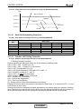
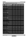
SW 35V14 and above
NLOAD
Target Frequency [Hz]
0
0
0 < NLOAD ≤ MinFreq
MinFreq
> MinFreq
MaxFreq MinFreq
{min (NLOAD, LoadDeadZone) MinFreq} MinFreq
LoadDeadZone MinFreq
Differences between Old and New ODU DCI/DCR software
Unit
DCI
Current software
35V12
New software
35V14
Comment: there is no use for 35V13 software. This software is used in the past for Nordic countries. However, currently
it’s stopped completely from being used.
Graphical Illustration:
Target
Frequency
MaxFreq
LoadDeadZone
allowed in this range
Minimum Allowed
Linearization
Maximum Allowed
Linearization
MinFreq
(
MinFreq
MaxFreq
Mode
MaxFreq
MinFreq
LoadDeadZone
#
1
2
3
4
5
6
7
8
Name
MinFreqC
MaxFreqC
MaxFreqCRunPhase
MinFreqH
MaxFreqH
MaxFreqHRunPhase
LoadDeadZoneC
LoadDeadZoneH
13-2
NLOAD
)
LoadDeadZone
127
During initial period
(Start Phase)
After initial period
(Run Phase)
MaxFreqC
MaxFreqH
MaxFreqCRunPhase
MaxFreqHRunPhase
Cool
Heat
Cool
Heat
Cool
Heat
MinFreqC
MinFreqH
LoadDeadZoneC
LoadDeadZoneH
A
Single
DCI-25
30
64
64
30
81
81
90
127
B
Single
DCI-35
33
80
80
35
93
93
95
127
C
Single
DCI-50
20
85
85
20
95
95
95
127
D
Single
DCI 60
20
95
95
26
94
94
111
127
CONTENT
E
Duo
50
20
97
97
26
106
106
97
106
F
DCR
50
20
77
77
26
79
79
90
127
G
Duo
Delta38
38
93
85
38
100
90
93
100
H
Trio
Delta52
20
100
95
25
100
95
127
100
I
DCR
50T
20
77
77
26
79
79
90
127
SM DLF 1-A.1 GB
CONTROL SYSTEM
Target frequency limits as a function of outdoor air temperature (OAT):
OAT Range
Cooling Mode limits
OAT < 6
No limit
6 ≤ OAT < 15
MaxFreqAsOATC
15≤ OAT<28
28≤ OAT
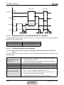
13.1.4
Heating Mode limits
MaxFreqAsOAT1H
MaxFreqAsOAT2H
No limit
Frequency Changes Control
When the unit is running normally , the compressor frequency change rate is 1 Hz/sec.
13.1.5
13.1.5.1
Compressor Starting Control
Compressor starting control for DCI25/35/50/60
Step3
Step2
Step1
1
Minute
13.1.5.2
1
Minute
Time
Min 10 Minutes
Compressor starting control for DCI72Z
Step 1
Whenever the compressor starts up, after it has been off for more than 45 minutes, the compressor
frequency cannot go below Step1RPS for 3 continuous minutes (this rule comes to ensure oil return
to the compressor).
Step 2
The compressor speed cannot go above Step2RPS once after each compressor start up for 3
continuous minutes (this rule comes to prevent oil exit from the compressor after its start up).
Step 3
The speed cannot go higher than Step3RPS unless it was operating for more than 1 continuous
minutes between Step3RPS – 5 and Step3RPS .
After passing above Step3RPS, this rule is re-applied when passing below Step3RPS-5.
SM DLF 1-A.1 GB
CONTENT
13-3
CONTROL SYSTEM
13.1.6
Minimum On and Off Time
3 minutes
13.1.7
Indoor Fan Control
8 Indoor fan speeds are determined for each model. 4 speeds for cool/dry/fan modes and 4speeds
for heat mode.
When user sets the indoor fan speed to a fixed speed (Low/ Medium/ High), unit will operate constantly
at set speed.
When Auto Fan is selected, indoor unit controller can operate in all speeds. The actual speed is set
according to the cool/heat load.
13.1.7.1
Turbo Speed
The Turbo speed is activated during the first 30 minutes of unit operation when auto fan speed is
selected and under the following conditions:
Difference between set point and actual room temperature is bigger then 3 degrees.
Room temperature > 22 for cooling, or < 25 for heating.
13.1.8
Outdoor Fan Control
13.1.8.1
Outdoor Fan Control for DCI25/35/50/60
7 outdoor fan speeds are determined for each model. 3 speeds for cool and dry modes, and 3speeds
for heat mode, and a very low speed.
Outdoor fan speed is a function of compressor frequency and outdoor air temperature (OAT).
4 routines for fan control are determined. The control routine selection depends on operation mode,
compressor speed, outdoor air temperature (OAT) and heat sink temperature (HST).
Routine
Conditions
Heating with OAT < 15ഒ or
Cooling with OAT > 20ഒ, or Faulty OAT
Cooling with 20ഒ > OAT > 7ഒ
Cooling with 7ഒ > OAT
Heating with OAT > 15ഒ
A
B
C
D
OFAN Speed
Compressor
Target Frequency
Freq=0
10 ≤ Freq < OFLowFreq
OFLowFreq
OFMedFreq
≤
OFMedFreq≤ Freq
13-4
Freq<
Routin
A
OFF
Low
Routin
B
OFF
Low
Routin
C
OFF
VL
Routin
D
OFF
Low
Medium
Low
VL
Low
High
Low
Low
Medium
CONTENT
SM DLF 1-A.1 GB
CONTROL SYSTEM
OFAN State
at Cool Mode $
HST
3 Degrees
Change To Higher
OFAN Cool state (*1)
3 Degrees
%
50
&
2$7
45
Change To lower
OFAN Cool state
Note: Periorities A>B>C
(*1) If
State C, change to B
If State B, change to A
When compressor is switched to OFF and the heat sink temperature is above 55 degrees, the
outdoor fan will remain ON in low speed for up to 3 minutes.
13.1.8.2
Outdoor Fan Control for DCI72Z
OFAN operates between OFMinRPM to OFMaxRPM.
Min time for speed change of OFAN OFMinTimeReduce (60 seconds).
There are 4 defined speeds – High, Med, Low, and Very Low.
The actual OFAN speeds in cool mode are defined according to the following table:
Freq
0
15
25
35
45
55
65
75
85
95
-10
0
80
130
160
205
250
275
300
325
350
-5
0
100
140
180
230
280
315
350
395
440
0
0
120
160
210
260
310
355
400
445
490
Outdoor air temperature (OAT)
5
10
15
20
25
30
0
0
0
0
0
0
130 220 340 460 580 600
190 250 380 600 610 670
250 330 470 730 730 730
320 440 600 730 730 730
390 550 730 730 730 730
470 640 730 730 730 730
550 730 730 730 730 730
630 730 730 730 730 730
710 730 730 730 730 730
35
0
730
730
730
730
730
730
730
730
730
40
0
730
740
780
800
800
800
800
800
800
46
0
730
750
800
850
850
850
850
850
850
The actual OFAN speeds in heat mode are defined according to the following table
Freq
0
15
25
35
45
55
65
75
85
95
-15
0
850
850
850
850
850
850
850
850
850
Outdoor air temperature (OAT)
-7
0
7
14
21
24
0
0
0
0
0
0
850 750 750 500 350 300
850 750 750 520 370 320
850 750 750 540 390 340
850 750 750 560 410 360
850 750 750 580 430 380
850 750 750 600 450 400
850 750 750 620 470 420
850 750 750 640 490 440
850 750 750 650 500 450
The fan speed is also related to protections and OMT value.
SM DLF 1-A.1 GB
CONTENT
13-5
CONTROL SYSTEM
13.1.9
EEV (Electronic Expansion Valve) Control
13.1.9.1 EEV Control for DCI25/35/50/60
EEV opening is defined as EEV = EEVOL + EEVCV
EEVOL is the initial EEV opening as a function of the compressor frequency, operation mode, unit
model and capacity.
EEVCV is a correction value for the EEV opening that is based on the compressor temperature.
During the first 5 minutes of compressor operation EEVCV = 0.
Once the first 5 minutes are over, the correction value is calculated as follow: EEVCV(n) = EEVCV(n-1)
+ EEVCTT
EEVCTT is the correction based on the compressor temperature. A target compressor temperatureзs
set depending on frequency and outdoor air temperature, and the actual compressor temperature is
compared to the target temperature to set the required correction to the EEVopening.
13.1.9.2
EEV Control for DCI72Z
The target EEV value is the sum of open loop value (OL) and a result of the accumulative correction
values (CV).
EEV EEVOL EEVCV
Initial EEV value is set according to compressor frequency and according to indoor and outdoor
model
The corrective value is calculate every 30 sec the EEV corrective value is set to keep the discharged
super heat temperature between 20º to 30º in cooling and 12º to 20º in heating.
13-6
CONTENT
SM DLF 1-A.1 GB
CONTROL SYSTEM
13.1.10
RV(Reversing Valve) Control
Reversing valve is on in heat mode.
Switching of RV state is done only after compressor is off for over 3 minutes.
13.1.10.1 Ioniser Control
Ioniser is on when unit is on ,AND indoor fan is on ,AND Ioniser power switch (on grille) is on.
13.1.10.2 Base Heater Control
The base heater will be working only when RV is “ON” according to the following graph:
Base
Heater
OFF
ON
0
2
OAT
When OAT is faulty the base heater will be “ON” continuously in HEAT mode.
13.1.11
Fan Mode
In high/ medium/ low indoor fan user setting, unit will operate fan in selected speed.
In AutoFan user setting, fan speed will be adjusted automatically according to the difference between
actual room temperature and user set point temperature.
13.1.12
Cool Mode
NLOAD is calculated according to the difference between actual room temperature and user set
point temperature by fuzzy control.
In high/ medium/ low indoor fan user setting, unit will operate fan in selected speed.
In AutoFan user setting, fan speed will be adjusted automatically according to the calculated
NLOAD.
13.1.13
Heat Mode
NLOAD is calculated according to the difference between actual room temperature and user set
point temperature by fuzzy control.
In high/ medium/ low indoor fan user setting, unit will operate fan in selected speed.
In AutoFan user setting, fan speed will be adjusted automatically according to the calculated
NLOAD.
13.1.13.1 Temperature Compensation
In ducted and cassette models, 3 degrees are reduced from room temperature reading (except when
in I-Feel mode), to compensate for temperature difference between high and low areas in the heated
room, and for coil heat radiation on room thermistor.
The temperature compensation can be enabled/disabled by shortening of J2 on the indoor unit
Controller
Model
Cassette
Ducted
SM DLF 1-A.1 GB
J2 Shorted
Compensation Enabled
Compensation Enabled
CONTENT
J2 Opened
Compensation Disabled
Compensation Disabled
13-7
CONTROL SYSTEM
13.1.13.2 Indoor Fan Control in Heating Mode
Indoor fan speed depends on the indoor coil temperature:
13.1.14
Auto Cool/Heat Mode
When in auto cool heat mode unit will automatically select between cool and heat mode according to
the difference between actual room temperature and user set point temperature (.T).
Unit will switch from cool to heat when compressor is off for 3 minutes, and .T < -3.
Unit will switch from heat to cool when compressor is off for 5 minutes, and .T < -3.
13.1.15
Dry Mode
As long as room temperature is higher then the set point, indoor fan will work in low speed and
compressor will work between 0 and MaxNLOADIF1C Hz.
When the room temperature is lower than the set point, compressor will be switched OFF and indoor
fan will cycle 3 minutes OFF, 1 minute ON.
13.1.16
Protections
There are 5 protection codes.
Normal (Norm) – unit operate normally.
Stop Rise (SR) – compressor frequency can not be raised but does not have to be decreased.
HzDown1 (D1) – Compressor frequency is reduced by 2 to 5 Hz per minute.
HzDown2 (D2) – Compressor frequency is reduced by 5 to 10 Hz per minute.
Stop Compressor (SC) – Compressor is stopped.
13.1.16.1 Indoor Coil Defrost Protection — CK
Min(ICT,ICTE)
< -2
[-2, 0)
[0, 2)
[2, 4)
[4, 6)
[6, 8]
>8
13-8
Trend
Fast Increasing
SC
D1
SR
SR
Norm
Norm
Increasing
SC
D1
SR
SR
Norm
Norm
No Change
SC
D2
D1
SR
SR
Norm
Norm
CONTENT
Decreasing
SC
D2
D2
D1
SR
SR
Fast Decreasing
SC
D2
D2
D2
D1
SR
SM DLF 1-A.1 GB
CONTROL SYSTEM
13.1.16.2 Indoor Coil Defrost Protection — DLF
ICT
< -2
[-2, 0)
[0, 2)
[2, 4)
[4, 6)
[6, 8]
>8
Trend
Fast Increasing
SC
D1
SR
SR
Norm
Norm
Increasing
SC
D1
SR
SR
Norm
Norm
No Change
SC
D2
D1
SR
SR
Norm
Norm
Decreasing
SC
D2
D2
D1
SR
SR
Fast Decreasing
SC
D2
D2
D2
D1
SR
13.1.16.3 Indoor Coil Overheating Protection
ICT
ICT Trend
Fast Decreasing
>62
[60, 62)
[55, 60)
[52, 55)
[48, 52)
[45, 48)
I<45
13.1.17
SC
D1
SR
SR
Norm
Norm
Decreasing
SC
D1
SR
SR
Norm
Norm
No Change
Increasing
Fast Increasing
SC
D2
D1
SR
SR
Norm
Norm
SC
D2
D2
D1
SR
SR
SC
D2
D2
D2
D1
SR
Compressor Overheating Protection
13.1.17.1 Compressor Overheating Protection for DCI25/35/50/60/72Z
Compressor temperature can be in one of 5 control zones (4 in protection, and 1 normal),
according to the following chart.
CTT
105
102
98
94
Stop-Compressor
P3
P2
P1
Normal
Control Status
Compressor Temperature Increases Else
P1
P2
P3
Stop Compressor
Normal
HzDown 1
HzDown 2
Stop Compressor
SM DLF 1-A.1 GB
CONTENT
Stop Rise
Stop Rise
HzDown 1
13-9
CONTROL SYSTEM
13.1.17.2 Compressor Over Current Protection Only For DCI25/35/50/60/72Z
CCR
Stop-Compresor
CCROC4
HzDown2
CCROC3
HzDown1
CCROC2
Stop-Rise
CCROC1
Normal
13.1.18
Heat Sink Overheating Protection
13.1.08.1 Heat Sink Overheating Protection For DCI25/35/50/60/72Z
HST Trend
HST
Fast Decreasing
≥ 90
[85, 90)
[82, 85)
[80, 82)
[78 , 80)
< 78
13.1.19
SC
D1
SR
SR
Norm
Decreasing
SC
D1
SR
SR
Norm
No Change
SC
D2
D1
SR
Norm
Norm
Increasing
SC
D2
D2
D1
SR
Fast Increasing
SC
D2
D2
D1
SR
Outdoor Coil Deicing Protection
13.1.19.1 Outdoor coil Deicing Protection For DCI25/35/50/60/72Z
•
Entering Deicing Conditions
Deicing operation will start when either one of the following conditions exist:
Case 1: OCT < OAT – 8 AND TLD > DI
Case 2: OCT < OAT – 12 AND TLD > 30 minutes.
Case 3: OCT is Invalid AND TLD > DI
Case 4: Unit is just switched to STBY AND OCT < OAT – 8
Case 5: NLOAD = 0 AND OCT < OAT -8
Case 6: OCT<-19 AND TLD>60 minutes
All this condition will exist during 10 seconds
OCT – Outdoor Coil Temperature
OAT – Outdoor Air Temperature
TLD – Time from Last Deicing
DI – Deicing Interval (Time Interval Between Two Deicing)
Deicing interval time when compressor is first started in heat mode, is 10 minutes if OCT < -2, and
is 40 minutes in other cases.
Deicing interval time is changed (increased/ decreased in 10 minutes steps) as a function of deicing
time. If deicing time is shorter then former deicing time, the deicing interval time will be increased. If
deicing time is longer then former deicing time, the deicing interval time will be decreased.
13-10
CONTENT
SM DLF 1-A.1 GB
CONTROL SYSTEM
•
Deicing Operation Procedure
OCT
12
0
T h re s h o ld
COMP
ON
T1
T1
T2
DT
m a x. 1 2 m in u te s
D e ic e F re q C h R V
HEAT
RV
T3
COOL
O FAN
T3
ON
OFF
E E V D e ic e rO p e n
EEV
Any
T1=60 secondes;T2=36 secondes;T3=6 secondes
T1=50 secondes;T2=36 secondes;T3=6 secondes
13.1.20
Condensate Water Over Flow Protection
P1
P2
P3
P4
Level Connector Top View
Each of the pins P1, P2, P3 can have two options:
1 – When it is shorted with P4
0 – When it is not shorted to P4
P1
P2
P3
Level
Don’t care
Don’t care
1
Normal
Don’t care
Don’t care
0
Overflow
(*) 1- Pin P1, P2, or P3 is connected to P4.
0- Pin P1, P2 or P3 is not connected to P4.
For DLF unit:
In case of vertical installation, change dipswitch 7 to OFF position to cancel Water Pump operation.
SM DLF 1-A.1 GB
CONTENT
13-11
CONTROL SYSTEM
Overflow when
unit is ON
Overflow
Water Level
Overflow when
unit is OFF
Normal
ON
OPER
LED
OFF
BLINK
ANY
NLOAD
NLOAD is
forced to 0
0
ON
PUMP
OFF
8 min
13.1.21
8 min
8 min
Operating the Unit from Mode Button (On display)
Forced operation allows to start, stop and operate in Cooling or Heating, in pre-set temperature
according to the following table:
Forced operation Mode
Cooling
Heating
13.1.22
Pre-set Temperature
20ഒ
28ഒ
On Unit Controls and Indicators
13.1.22.1 Indoor Unit controller Controls and Indicatiors for All Models Except for Floor/Ceiling
model
During OFF, Fan, Cool, Heat, Dry, and Auto modes (for operation in other modes, see at the relevant
spec paragraph):
STAND BY/OPERATION
INDICATOR
ESF/INOIZER INDICATOR
TIMER INDICATOR
FILTER INDICATOR
MODE/RESET BUTTON
13-12
Lights up when the Air Conditioner is connected to power and ready
to receive the R/C commands
Lights up during operations. Blinks when compressor is stopped as
a result of a thermodynamic protection.
Lights up during ESF/ ionizer operation.
Lights up during Timer and Sleep operation.
Lights up when Air Filter needs to be cleaned.
Every short pressing , the next operation mode is selected, in this
order :
SB → Cool Mode → Heat Mode → SB → …
Press to turn off the filter indicator and to reset the filter function,
after the cleaned filter has been reinstalled.
In long pressing the system enters into diagnostic mode.
CONTENT
SM DLF 1-A.1 GB
CONTROL SYSTEM
13.1.22.2 Outdoor Unit controller Indicatiors
Unit has three LED’s.
SB LED is ON when power is ON (230 VAC, even when no communication).
STATUS LED is ON when COMP is ON, and Blinks according to diagnostics mode definitions when
either fault or protection occurs.
FAULT LED Blinks according to diagnostics mode definitions when either fault or protection occurs.
13.1.23
DIP switch settings
Indoor Unit Controller
13.1.23.1 Power PCB - CK
PUMP
Wire to Main PCB
DC Motor Cable
13.1.23.2 Main PCB - CK
Self Test Jumper
DIP Switch
M2L Port
MCU Flash Port
12Pin Displayer Cable
Alarm Output
Unit On Output
RC-W
RC-W Power
PD/PS
Safety switch Terminals
ICTE Sensor
Inoizer
ICT Sensor
ESF
RAT Sensor
Swing Motor
Water Level
SM DLF 1-A.1 GB
CONTENT
13-13
CONTROL SYSTEM
13.1.23.3 Main PCB − DLF
MCU Flash Port
IF Motor
ICTE sensor
ICT sensor
RAT sensor
M2L Port
DIP Switch
WATER level
Unit On output
ALARM output
CLOCK
RCW Power
RCW
16 Pins Display (not used)
To Display
Water Pump
Fresh Air
13-14
CONTENT
SM DLF 1-A.1 GB
CONTROL SYSTEM
13.1.24
Self Test Jumper(J1))
● Jumper for production line only, never install jumper on site!
13.1.25 DIP Switch and Jumper Settings
● CK - Dip switch default setting for each model
1
2
3
4
5
6
7
8
J2
J3
J6
J7
J8
J9
J12
J13
2.5 KW
ON
OFF
OFF
OFF
OFF
OFF
ON
OFF
3.5 KW
ON
OFF
OFF
ON
OFF
OFF
ON
OFF
5.0 KW
ON
ON
OFF
OFF
OFF
OFF
ON
OFF
6.0 KW
ON
ON
OFF
ON
OFF
OFF
ON
OFF
7.0 KW
ON
ON
OFF
OFF
ON
OFF
ON
OFF
DIP
MODEL
J
● DLF - Dip switch default setting for each model
1
2
3
4
5
6
7*
8**
J2
J3
J5
J7
J8
J9
J10
J12
2.5 KW
ON
OFF
OFF
ON
OFF
OFF
ON
OFF
3.5 KW
ON
OFF
OFF
OFF
ON
OFF
ON
OFF
5.0 KW
ON
OFF
OFF
ON
ON
OFF
ON
OFF
6.0 KW
ON
ON
OFF
OFF
OFF
OFF
ON
OFF
7.0 KW
ON
ON
OFF
ON
OFF
OFF
ON
OFF
DIP
MODEL
J
*Water pump and float switch setting
In case of vertical installation, change dipswitch 7 to OFF position to cancel their operation.
**High external static pressure
There is an option of increasing the airflow if the ESP (external static pressure) is higher than
planned. To increase the speed change dipswitch 8 to ON position.
● Compensation setting (Factory setting)
This setting activates the compensation to the return air temperature in heating mode. For indoor unit
like cassette, the DIP switch J2 should be ON.
Compensation
Activated(factory setting)
Deactivated
J2
ON
OFF
● Unit model setting (Factory setting)
The unit model setting should be in accordance with the unit model on the nameplate. The unit
operating parameters will be improper with wrong settings.
Unit model(Capacity)
2.5kW model
3.5kW model
5.0kW model
6.0kW model
7.0kW model
SM DLF 1-A.1 GB
J3
OFF
OFF
ON
ON
ON
J6
OFF
OFF
OFF
OFF
OFF
J7
OFF
ON
OFF
ON
OFF
CONTENT
J8
OFF
OFF
OFF
OFF
ON
13-15
CONTROL SYSTEM
●
Presence Detector/Power Shedding Selection
Select the functions of dry contact PD/PS by setting the Dip switch J9
Selection
Presence Detector
Power Shedding
●
J9
OFF
ON
Installation of height compensation settings (By installer)
The compensation settings according to installation height should be set by using the dip switch J12,
J13 on the controller PCB
Installation Height
H0
H1(Factory setting)
H2
H3
J12
OFF
ON
OFF
ON
J13
OFF
OFF
ON
ON
Installation height
2.1-2.7m
2.7-3.3m
>3.3m
Reserved
Compensation data according to the installation height
Installation
Height
H0
H1
H2
H3
13-16
Speed Compensation for
Heating Mode
Speed Compensation for
other Modes
Temperature compensation
in heating mode
CK
DLF
CK
DLF
CK
DLF
-50
0
100
150
0
150
150
150
-50
0
100
150
0
150
150
150
4
4
6
7
2
2
2
2
CONTENT
SM DLF 1-A.1 GB
CONTROL SYSTEM
IDU Diagnostic Table.
● Alarm Output
The Alarm Output dry contact will be on (closed), when a predefined set faults occur.
The fault set is defined under diagnostics section.
The alarm output will be off (open), when the predefined fault is cleared.
The indoor alarm outputs are defined according to the following IDU Diagnostic Table:
No
Problem
AO
5
4
3
2
1
1
ICT is disconnected
Yes
0
0
0
0
1
2
ICT is shorted
Yes
0
0
0
1
0
3
RAT is disconnected
Yes
0
0
0
1
1
4
RAT is shorted
Yes
0
0
1
0
0
5
Reserved (for MSMP used as RGT fault)
No
0
0
1
0
1
ICTE shorted/disconnected (when enabled)
Yes
0
0
1
1
0
7
Undefined IDU family/model
Yes
0
0
1
1
1
8
No Communication
Yes
0
1
0
0
0
9
No Encoder
No
0
1
0
0
1
10
Reserved
No
0
1
0
1
0
11
Outdoor Unit Fault
No
0
1
0
1
1
…
Reserved
No
17
Defrost protection
No
1
0
0
0
1
18
Deicing Protection
No
1
0
0
1
0
19
Outdoor Unit Protection
No
1
0
0
1
1
20
Indoor Coil HP Protection
No
1
0
1
0
0
21
Overflow Protection
Yes
1
0
1
0
1
22
Reserved
No
24
EEPROM Not Updated
No
1
1
0
0
0
25
Bad EEPROM
No
1
1
0
0
1
26
Bad Communication
No
1
1
0
1
0
27
Using EEPROM data
No
1
1
0
1
1
28
Model A
No
1
1
1
0
0
29
Model B
No
1
1
1
0
1
30
Model C
No
1
1
1
1
0
31
Model D
No
1
1
1
1
1
*6
* CK Unit only
SM DLF 1-A.1 GB
CONTENT
13-17
CONTROL SYSTEM
OUD Diagnostic Table
AO - Alarm output
No
Problem
AO
5
4
3
2
1
1
OCT is disconnected
Yes
0
0
0
0
1
2
OCT is shorted
Yes
0
0
0
1
0
3
CTT is disconnected
Yes
0
0
0
1
1
4
CTT is shorted
Yes
0
0
1
0
0
5
HST is disconnected (when enabled)
Yes
0
0
1
0
1
6
HST is shorted (when enabled)
Yes
0
0
1
1
0
7
OAT is disconnected (when enabled)
Yes
0
0
1
1
1
8
OAT is shorted (when enabled)
Yes
0
1
0
0
0
9
TSUC is disconnected (when enabled)
Yes
0
1
0
0
1
10
TSUC is shorted (when enabled)
Yes
0
1
0
1
0
11
IPM Fault
Yes
0
1
0
1
1
12
Bad EEPROM
No
0
1
1
0
0
13
DC under voltage
Yes
0
1
1
0
1
14
DC over voltage
Yes
0
1
1
1
0
15
AC under voltage
Yes
0
1
1
1
1
16
Mismatch IDU & ODU models (*SW 35V14 and above)
Yes
1
0
0
0
0
17
No Communication
Yes
1
0
0
0
1
18
Reserved
No
1
0
0
1
0
20
Heat sink Over Heating
No
1
0
1
0
0
21
Deicing
No
1
0
1
0
1
22
Compressor Over Heating
No
1
0
1
1
0
23
Compressor Over Current
No
1
0
1
1
1
24
No OFAN Feedback
No
1
1
0
0
0
25
OFAN locked
Yes
1
1
0
0
1
26
Compressor Lock
Yes
1
1
0
1
0
27
Bad Communication
No
1
1
0
1
1
28
Missing ODU configuration (*SW 35V14 and above)
Yes
1
1
1
0
0
29
Undefined ODU Model (*SW 35V14 and above)
Yes
1
1
1
0
1
30
For future use
No
1
1
1
1
0
31
Operation condition is exceeded (*SW 35V14 and above)
Yes
1
1
1
1
1
*Alarm Output - is on SW 35V14 and above. There is no alarm on SW 35V12 and below/
● Unit ON Output
The ‘On/Off status’ dry contact will be on (closed), when the indoor mode is not STBY.
If the indoor mode is STBY mode, the ‘On/Off status’ will be off (open).
●
PD/PS(Presence Detector/Power Shedding)
Function
J9=open
J9=short
13-18
Presence Detector Connection
Power Shedding Function
Contact=open
Contact=short
Last Mode
No limit
Force to STBY
Limit NLOAD
CONTENT
SM DLF 1-A.1 GB
CONTROL SYSTEM
13.1.25
Outdoor Unit Controller
13.1.25.1 Outdoor Unit Controller - Jumper setting
JP9 Jumper Layout
Reserved (PIN 9)
ODU3 (PIN 7)
ODU2 (PIN 5)
ODU1 (PIN 3)
ODU0 (PIN 1)
GND (PIN 10)
GND (PIN 8)
GND
GND
GND
13.1.26
(PIN 6)
(PIN 4)
(PIN 2)
ODU Model Selection
ODU3
ODU2
ODU1
ODU0
ODU Model
OFF
OFF
OFF
ON
A (Single DCI 25)
OFF
OFF
ON
OFF
B (Single DCI 35)
OFF
OFF
ON (PIN3 & PIN4)
ON (PIN1 & PIN2)
C (Single DCI 50)
OFF
ON (PIN5 & PIN6)
OFF
OFF
D (Single DCI 60)
ON (PIN7 & PIN8)
ON (PIN5 & PIN6)
OFF
OFF
L (Single DCI 72Z)
13.1.27
Outdoor Unit Controller
ON
1
N.A.
N.A.
ODU3
ODU2
ODU1
ODU0
13.1.27.1 Outdoor Unit Controller - DIP Switch setting
DIP
2
3
4
5
6
ODU MODEL SETTING
ODU3
ODU2
ODU1
ODU0
OFF
OFF
OFF
OFF
ON
OFF
OFF
OFF
ON
ON
OFF
ON
ON
OFF
OFF
ON
OFF
ON
OFF
OFF
13.2
Test Mode
13.2.1
Entering Test Mode
ODU MODEL
DCI 25
DCI 35
DCI 50
DCI 60
DCI 72Z
System can enter Test mode in two ways:
Automatically when the following conditions exists for 30 minutes continuously:
Mode = Cool, Set point = 16, Room temperature = 27(+1/-2), Outdoor temperature = 35(+2/-1)
Or
Mode = Heat, Set point = 30, Room temperature = 20±1, Outdoor temperature = 7±(+1/-2)
Manually when entering diagnostics with the following settings:
Mode = Cool, Set point = 16
Mode = Heat, Set point = 30
SM DLF 1-A.1 GB
CONTENT
13-19
CONTROL SYSTEM
13.2.3
Unit Operation in Test Mode
In test mode, the unit will operate in fixed settings according to the indoor fan speed setting:
Indoor FAN Speed Setting
Unit Setting
Low
Minimum Capacity Setting
Turbo
Nominal Capacity Setting
Auto
Maximum Capacity Setting
During test mode, protections are disabled, except for stop compressor status.
13.3
Parameters
13.3.1
General Parameters for all models
#
Name
1
CVStep
0
2
Cool2Heat
3
3
Heat2Cool
3
4
ICTDef1
8
5
ICTDef2
6
6
ICTDef3
4
7
ICTDef4
2
8
ICTDef5
0
9
ICTDef6
-2
10
ICTDeltaDef1
1
11
ICTDeltaDef2
-1
12
ICTDeltaOH1
-1
13
ICTDeltaOH2
1
14
FLTRTime
1023
15
PITconst
30
16
STARTTIMETURBOH
10
17
IFANOffTimeDry
3
18
IFANOnTimeDry
1
19
ICTLowLimitDry
10
20
ICTHighLimitDry
12
21
ExtraNLOADDry
20
22
IFANMAXTimeH
150
23
IFANOffTimeH
4
24
IFANOnTimeH
3
25
IFANTimeHeat2STBY
30
26
MAXTURBOTIMEF
30
27
MAXTURBOTIMEC
30
28
MAXTURBOTIMEH
30
13-20
Values(Factory Setting)
CONTENT
SM DLF 1-A.1 GB
CONTROL SYSTEM
13.3.2
Family Dependent Parameter
#
Name
CKA
CKB
1
BasicCV1
4
4
2
2
2
BasicCV2
4
4
2
2
3
BasicCV3
6
6
2
2
4
BasicCV4
7
7
2
2
5
Max_Swg
40
40
NA
NA
6
Min_H_Angle
5
5
NA
NA
7
Max_H_Angle
40
40
NA
NA
8
Min_C_Angle
5
5
NA
NA
9
Max_C_Angle
40
40
NA
NA
10
MTR_Cls_Dir
C
C
NA
NA
11
MTR_Cls_Dir_V
C
C
NA
NA
12
Max_Angle_V
NA
NA
NA
NA
13
Min_Angle_V
NA
NA
NA
NA
14
Max_Swg_V
NA
NA
NA
NA
15
IFSPCHNA
10
10
10
10
16
IFSPCHND
4
4
10
10
17
IFSPCHAA
6
6
6
6
18
IFSPCHAD
4
4
6
6
19
IFSTARTSPEED
670
670
670
670
20
ICTSTSpeed
25
25
25
25
21
ICTVLSpeed
28
28
28
28
22
ICTLSpeed
30
30
30
30
23
ICTHSpeed
32
32
32
32
24
ICTTSpeed
40
40
35
35
25
NLOADHForcedValue
60
60
60
60
26
ICTOH1
45
45
49
49
27
ICTOH2
48
48
51
51
28
ICTOH3
52
52
53
53
29
ICTOH4
55
55
55
55
30
ICTOH5
60
60
60
60
31
ICTOH6
62
62
62
62
32
ICTEEnable
1
1
0
0
SM DLF 1-A.1 GB
CONTENT
DLFA
DLFB
13-21
CONTROL SYSTEM
13.3.3
Indoor Model Parameters:
C (CK72)
A (DLF25)
B (DLF35)
C (DLF50)
A (DLF60)
B (DLF72)
DLFB
B (CK 60)
DLFA
A (CK50)
CKB
B (CK 35)
CKA
A (CK25)
Indoor Family
IFVLOWC
250
300
450
500
550
670
690
800
900
900
IFLOWC
450
450
550
600
650
740
730
860
960
980
IFMEDC
500
520
620
660
700
810
860
980
1050
1050
IFHIGHC
550
600
680
720
750
920
980
1100
1170
1200
IFTURBOC
650
700
800
900
1000
960
1060
1170
1240
1280
IFVLOWH
250
300
450
500
550
670
690
800
900
900
IFLOWH
450
450
550
600
650
740
730
860
960
980
IFMEDH
520
550
620
660
700
810
860
980
1050
1050
IFHIGHH
600
650
680
720
750
920
980
1100
1170
1200
IFTURBOH
650
700
850
950
1000
960
1060
1220
1240
1280
Cap .Group
0
1
3
3
4
0
1
3
3
4
NomLoadC
40
62
66
81
62
40
60
64
79
54
NomLoadH
52
67
67
81
57
57
70
73
82
57
MaxNLOADIF1C
47
42
55
56
50
127
127
127
127
127
MaxNLOADIF2C
70
60
78
81
70
127
127
127
127
127
MaxNLOADIF3C
127
127
127
127
127
127
127
127
127
127
MaxNLOADIF4C
127
127
127
127
127
127
127
127
127
127
MaxNLOADIF5C
127
127
127
127
127
127
127
127
127
127
IFAN_SPEED_COMP0_C
-50
-50
-50
-50
-50
0
0
0
0
0
IFAN_SPEED_COMP1_C
0
0
0
0
0
150
150
150
150
150
IFAN_SPEED_COMP2_C
100
100
100
100
100
150
150
150
150
150
IFAN_SPEED_COMP3_C
150
150
150
150
150
150
150
150
150
150
IFAN_SPEED_COMP0_H
-50
-50
-50
-50
-50
0
0
0
0
0
IFAN_SPEED_COMP1_H
0
0
0
0
0
150
150
150
150
150
IFAN_SPEED_COMP2_H
100
100
100
100
100
150
150
150
150
150
IFAN_SPEED_COMP3_H
150
150
150
150
150
150
150
150
150
150
1
1
1
1
1
1
1
1
1
1
Indoor Model
Parameter
ModelEnable
13-22
CONTENT
SM DLF 1-A.1 GB
CONTROL SYSTEM
13.3.4
Outdoor Parameters
General Parameters ( for every software):
#
Name
Default Value
1
MinOFFTime
3
2
MinONTime
3
3
OFSPCH
4
4
Down1
3
5
Down2
10
6
DImin
30
7
DImax
120
8
TimeD
1
9
DTmin
2
10
DTmax
12
11
DIT
10
12
CTMRUP
15
13
DIF
30
14
TCT
10
15
HSTOH1
78
17
HSTOH2
80
18
HSTOH3
82
19
HSTOH4
85
20
HSTOH5
90
21
HSTOHDelta1
-1
22
HSTOHDelta2
1
23
EEVCVTConst
30
24
BalanceTime
5
25
EEVInitOpen
300
SM DLF 1-A.1 GB
CONTENT
13-23
CONTROL SYSTEM
13.3.5
#
1
2
3
4
5
6
7
8
9
10
11
12
13
14
15
16
17
18
19
20
21
22
23
24
25
26
27
28
29
30
31
32
33
34
35
36
37
38
39
40
41
42
43
44
45
46
47
48
49
50
51
52
53
54
55
56
57
58
59
60
61
62
63
13-24
ODU Model Dependent Parameters ( 35V12 )
Outdoor Model
Parameter
MinFreqC
MaxFreqC
MinFreqH
MaxFreqH
NormAccel
NormDecel
Step1Freq
Step2Freq
Step3Freq
OFVL
OFLOWC
OFMEDC
OFMAXC
OFLOWH
OFMEDH
OFMAXH
OFANTESTMODEC
OFANTESTMODEH
OFDelTestMode
CTTOH1
CTTOH2
CTTOH3
CTTOH4
CCROC1
CCROC2
CCROC3
CCROC4
DEICT1
DEICT2
DEICT3
ProtFreqLimit
EEVDecierOpen
OptimDeicFreq
EEVMinOperOpenC
EEVMaxOperOpenC
EEVMinOperOpenH
EEVMaxOperOpenH
EEVNormRate
EEVHighRate
EEVMaxOpen
OFLowFreqC
OFMedFreqC
OFLowFreqH
OFMedFreqH
HeaterDisableFlag
DeiceFreqChRV
OATRefC
SUCT Enable
HST Enable
OAT Enable
OATRefH
MinTargCTTC
MaxTargCTTC
MinTargCTTH
MaxTargCTTH
DST
DSTF
OATLimitC
OATLimit1H
OATLimit2H
MaxFreqAsOATC
MaxFreqAsOAT1H
MaxFreqAsOAT2H
A
Single
DCI-25
B
Single
DCI-35
C
Single
DCI-50
D
Single
DCI 60
30
64
30
81
1
1
60
70
90
20
55
70
83
55
70
83
83
83
20
94
98
102
105
7.1
7.5
7.9
8.3
60
36
6
60
180
90
50
380
50
300
33
12
500
45
57
45
57
0
0
35
0
0
1
7
30
95
40
95
8
12
24
6
15
50
65
60
33
80
35
93
1
1
60
70
90
20
55
70
83
55
70
83
83
83
20
94
98
102
105
7.1
7.5
7.9
8.3
60
36
6
60
180
90
50
380
50
300
33
12
500
45
57
45
57
0
0
35
0
0
1
7
30
95
40
95
8
12
24
6
15
50
75
60
20
85
20
95
1
1
60
70
90
20
60
76
92
60
83
100
92
100
28
94
98
102
105
10
10.5
10.8
11.2
60
36
6
60
100
90
50
380
50
380
33
12
500
40
70
40
86
0
0
35
0
1
1
7
30
95
40
95
8
12
28
6
15
64
85
60
20
95
26
94
1
1
60
70
90
20
55
70
79
55
70
79
83
83
28
94
98
102
105
11.4
11.8
12.2
12.6
60
36
6
60
180
90
80
380
60
300
33
12
500
35
55
40
60
0
0
35
0
1
1
7
30
90
45
90
8
12
28
6
15
85
80
60
CONTENT
SM DLF 1-A.1 GB
CONTROL SYSTEM
13.3.6
#
1
2
3
4
5
6
7
8
9
10
11
12
13
14
15
16
17
18
19
20
21
22
23
24
25
26
27
28
29
30
31
32
33
34
35
36
37
38
39
40
41
42
43
44
45
46
47
48
49
50
51
52
53
54
55
56
57
58
59
60
61
62
63
64
65
66
67
68
68
69
ODU Model Dependent Parameters ( 35V14 )
Outdoor Model
Parameter
MinFreqC
MaxFreqC
MaxFreqCRunPhase
MinFreqH
MaxFreqH
MaxFreqHRunPhase
LoadDeadZoneC
LoadDeadZoneH
NormAccel
NormDecel
Step1Freq
Step2Freq
Step3Freq
OFVL
OFLOWC
OFMEDC
OFMAXC
OFLOWH
OFMEDH
OFMAXH
OFANTESTMODEC
OFANTESTMODEH
OFDelTestMode
CTTOH1
CTTOH2
CTTOH3
CTTOH4
CCROC1
CCROC2
CCROC3
CCROC4
DEICT1
DEICT2
DEICT3
ProtFreqLimit
EEVDecierOpen
OptimDeicFreq
OCTExitDeicer
MaxDeicerTime
EEVMinOperOpenC
EEVMaxOperOpenC
EEVMinOperOpenH
EEVMaxOperOpenH
EEVNormRate
EEVHighRate
EEVMaxOpen
OFLowFreqC
OFMedFreqC
OFLowFreqH
OFMedFreqH
HeaterDisableFlag
DeiceFreqChRV
OATRefC
SUCT Enable
HST Enable
OAT Enable
OATRefH
MinTargCTTC
MaxTargCTTC
MinTargCTTH
MaxTargCTTH
DST
DSTF
OATLimitC
OATLimit1H
OATLimit2H
MaxFreqAsOATC
MaxFreqAsOAT1H
MaxFreqAsOAT2H
EnableExceedCond
SM DLF 1-A.1 GB
A
Single
DCI-25
B
Single
DCI-35
C
Single
DCI-50
D
Single
DCI 60
30
64
64
30
81
81
90
127
1
1
60
70
90
20
55
70
83
55
70
83
83
83
20
94
98
102
105
7.1
7.5
7.9
8.3
60
36
6
60
180
90
12
12
50
380
50
300
33
12
500
45
57
45
57
0
0
35
0
1
1
7
30
95
40
95
8
12
24
6
15
50
65
60
0
33
80
80
35
93
93
95
127
1
1
60
70
90
20
55
70
83
55
70
83
83
83
20
94
98
102
105
7.1
7.5
7.9
8.3
60
36
6
60
180
90
12
12
50
380
50
300
33
12
500
45
57
45
57
0
0
35
0
1
1
7
30
95
40
95
8
12
24
6
15
50
75
60
0
20
85
85
20
95
95
95
127
1
1
60
70
90
20
60
76
92
60
83
100
92
100
28
94
98
102
105
10
10.5
10.8
11.2
60
36
6
60
100
90
12
12
50
380
50
380
33
12
500
40
70
40
86
0
0
35
0
1
1
7
30
95
40
95
8
12
28
6
15
64
85
60
0
20
95
95
26
94
94
111
127
1
1
60
70
90
20
55
70
79
55
70
79
83
83
28
94
98
102
105
11.4
11.8
12.2
12.6
60
36
6
60
180
90
12
12
80
380
60
300
33
12
500
35
55
40
60
0
0
35
0
1
1
7
30
90
45
90
8
12
28
6
15
85
80
60
0
CONTENT
13-25
CONTROL SYSTEM
13.3.7
ODU Model Dependent Parameters ( 36V1-S01 )
Outdoor Model
#
Parameter
13-26
L
Single
DCI-72Z
1
MinFreqC
15
2
MaxFreqC
70
3
MinFreqH
15
4
MaxFreqH
90
7
Step1Freq
35
8
Step2Freq
55
9
Step3Freq
90
10
OFMinRPM
8
11
OFMaxRPM
90
12
NightRPM
65
13
OFNNoiseMaxRPM
78
14
CTTOH1
90
15
CTTOH2
95
16
CTTOH3
100
17
CTTOH4
105
18
CCROC1
12.5
19
CCROC2
13.3
20
CCROC3
14.1
21
CCROC4
14.9
22
ProtFreqLimit
60
23
EEVMinOperOpenC
50
24
EEVMaxOperOpenC
480
25
EEVMinOperOpenH
50
26
EEVMaxOperOpenH
480
27
HeaterDisableFlag
0
28
HST Enable
1
29
OATLimitC
25
30
OATLimit1H
4
31
OATLimit2H
15
32
MaxFreqAsOATC
60
33
MaxFreqAsOAT1H
68
34
MaxFreqAsOAT2H
57
35
NormAccel
1
36
NormDecel
1
37
38
OCTExitDeicer
MaxDeicerTime
12
15
CONTENT
SM DLF 1-A.1 GB
TROUBLESHOOTING
14.
TROUBLESHOOTING
WARNING!!!
When Power Up – the whole outdoor unit controller, including the wiring, is under
HIGH VOLTAGE!!!
Never open the Outdoor unit before turning off the Power!!!
When turned off, the system is still charged (400V)!!!
It takes about 3 Min. to discharge the system.
Touching the controller before discharging may cause an electrical shock!!!
For safe handling of the controller please refer to section 14.6 below.
14.1
General DCI Single Split System failures and Corrective Actions
PROBABLE
CAUSE
No
SYMPTOM
1
Power supply indicator (Red
LED) does not light up.
No power supply
Check power supply. If power supply
is OK, check display and display
wiring. if OK, replace controller.
2
Unit does not respond to
remote control message
Remote
control
message not reached
the indoor unit
Check remote control batteries, if
batteries are OK, check display and
display wiring, if OK, replace display
PCB.
If still not OK replace controller.
3
Unit responds to remote
control message but Operate
indicator (Green LED) does
not light up
Problem with display
PCB
Replace display PCB.
If still not OK replace controller.
Unit in heat mode and
coil is still not warm.
Change to cool mode and check.
Problem with PCB or
capacitor
Change to high speed and Check
power supply to motor is higher than
130VAC (for triack controlled motor)
or higher than 220VAC for fixed speed
motors, if OK replace capacitor, if not
OK replace controller
5
Indoor fan works when unit
is OFF, and indoor fan speed
is not changed by remote
control command.
PCB problem
Replace controller
6
Compressor does not start
Electronics control
problem or protection
Perform diagnostics (See 14.3), and
follow the actions described.
7
Compressor stops during
operation and Green LED
remains on
Electronic control
or power supply
problem
Perform diagnostics (See 14.3), and
follow the actions described.
4
Indoor fan does not start
(louvers are opened and
Green LED does light up)
SM DLF 1-A.1 GB
CONTENT
CORRECTIVE ACTION
14-1
TROUBLESHOOTING
No
SYMPTOM
PROBABLE
CAUSE
CORRECTIVE ACTION
8
Compressor is on but outdoor
fan does not work
Problem with outdoor
electronics or
outdoor fan
Check outdoor fan motor according
to the procedure in section 14.5.3 , if
not OK replace controller
9
Unit works in wrong mode
(cool instead of heat or heat
instead of cool)
Electronics or power
connection to RV
Check RV power connections, if OK,
Check RV
operation with direct
230VAC power supply, if OK,
Replace outdoor controller.
10
All components are operating
properly but no cooling or no
heating
Refrigerant leak
Check refrigeration system.
11
Compressor is over heated
and unit does not generate
capacity
EEV problem
Check EEV
12
Units goes into protections
and compressor is stopped
with no clear reason
Control problem or
refrigeration system
problem
Perform diagnostics (See 14.3), and
follow the actions described.
13
Compressor
motor
generating noise and
suction occurs
Phase order to
compressor is wrong
Check compressor phase order.
14
Water leakage from indoor
unit
Indoor unit drainage
tube is blocked
Check and open drainage tube.
15
Freezing of outdoor unit in
heat mode and outdoor unit
base is blocked with ice
16
Unit operates with wrong fan
speeds or wrong frequency
14.2
is
no
Connect base heater.
Wrong jumper
settings
Perform diagnostics (See 14.3), and
check if units is operating by EEPROM
parameters.
Checking the refrigeration system
Checking system pressures and other thermodynamic measures should be done when system
is in Test Mode (in Test mode, system operates in fixed settings). The performance curves
given in this manual are given for unit performance in test mode when high indoor fan speed is
selected.
Entering test mode:
Set unit to Cool/16 degrees/High indoor fan speed, or Heat/30 degrees/High indoor fan speed,
and enter diagnostics.
14.3
Judgment by Indoor/Outdoor Unit Diagnostics
Enter diagnostics mode - press for five seconds Mode button in any operation mode.
Acknowledgment is by 3 short beeps and lights of COOL and HEAT LED’s. Then, every short
pressing of Mode button will scroll between Indoor and Outdoor unit diagnostic modes by the
acknowledgment of 3 short beeps and lighting of COOL and HEAT LED’s.
During the Outdoor unit diagnostics all four Indoor LED’s (STBY, Operate, Filter and Timer)
are blinking. When Indoor diagnostics is displayed, all four LED’s (STBY, Operate, Filter and
Timer) are ON.
14-2
CONTENT
SM DLF 1-A.1 GB
TROUBLESHOOTING
When system enters diagnostics mode, only one fault code is shown. Order of priority is from
the lower to the higher number. Diagnostics is continuously ON as long as power is ON. The
current system operation mode will not be changed.
If no fault occurred in the system, no fault code will be displayed during normal operation
mode. The last fault code will be displayed even if the system has recovered from that
fault. The last fault will be deleted from the EEPROM after the system has exit diagnostics
mode.
In diagnostics mode, system fault / status will be indicated by blinking of Heat & Cool LEDs.
The coding method will be as follows:
Heat LED will blink 5 times in 5 seconds, and then will be shut off for the next 5 seconds. Cool
LED will blink during the same 5 seconds according to the following Indoor / Outdoor unit
tables:
Note: 0 – OFF, 1-ON
14.3.1
Indoor Unit Diagnostics
●
Alarm Output
The Alarm Output dry contact will be on (closed), when a predefined set faults occur.
The fault set is defined under diagnostics section.
The alarm output will be off (open), when the predefined fault is cleared.
The indoor alarm outputs are defined according to the following table:
No
Problem
AO
5
4
3
2
1
1
ICT is disconnected
Yes
0
0
0
0
1
2
ICT is shorted
Yes
0
0
0
1
0
3
RAT is disconnected
Yes
0
0
0
1
1
4
RAT is shorted
Yes
0
0
1
0
0
5
Reserved (for MSMP used as RGT fault)
No
0
0
1
0
1
ICTE shorted/disconnected (when enabled)
Yes
0
0
1
1
0
Undefined IDU family/model
Yes
0
0
1
1
1
8
No Communication
Yes
0
1
0
0
0
9
No Encoder
No
0
1
0
0
1
10
Reserved
No
0
1
0
1
0
11
Outdoor Unit Fault
No
0
1
0
1
1
…
Reserved
No
17
Defrost protection
No
1
0
0
0
1
18
Deicing Protection
No
1
0
0
1
0
19
Outdoor Unit Protection
No
1
0
0
1
1
20
Indoor Coil HP Protection
No
1
0
1
0
0
21
Overflow Protection
Yes
1
0
1
0
1
22
Reserved
No
24
EEPROM Not Updated
No
1
1
0
0
0
25
Bad EEPROM
No
1
1
0
0
1
26
Bad Communication
No
1
1
0
1
0
27
Using EEPROM data
No
1
1
0
1
1
*6
*7
SM DLF 1-A.1 GB
CONTENT
14-3
TROUBLESHOOTING
No
Problem
AO
5
4
3
2
1
28
Model A
No
1
1
1
0
0
29
Model B
No
1
1
1
0
1
30
Model C
No
1
1
1
1
0
31
Model D
No
1
1
1
1
1
* CN / LSN Units only
14.3.2
Indoor Unit Diagnostics and Corrective Actions
No.
Fault
Probable Cause
Corrective Action
1
Sensor failures
of all types
Check sensor connections or
replace sensor
2
Communication
mismatch
Indoor and Outdoor
controllers are with
different versions
Replace Indoor controller
3
No
Communication
Communication or
grounding wiring is not
good.
Check Indoor to Outdoor
wiring and grounding
4
No Encoder
Indoor electronics or
motor
Check motor wiring, if ok,
replace motor, if still not ok,
replace Indoor controller.
5
Outdoor Unit
Fault
Outdoor controller
problem
Switch to Outdoor
diagnostics.
6
EEPROM Not
Updated
System is using ROM
parameters and not
EEPROM parameters
No action, unless special
parameters are required for
unit operation.
7
Bad EEPROM
8
Bad
Communication
Communication quality
is low reliability
9
Using EEPROM
data
No problem. System is
using EEPRRRROM
parameters
No action, unless special
parameters are required for
unit operation.
Check Indoor to Outdoor
wiring and grounding
14.3.3
Outdoor Unit Diagnostics
The outdoor alarm outputs are defined in the following way:
No
Problem
AO
5
4
3
2
1
1
OCT is disconnected
Yes
0
0
0
0
1
2
OCT is shorted
Yes
0
0
0
1
0
3
CTT is disconnected
Yes
0
0
0
1
1
4
CTT is shorted
Yes
0
0
1
0
0
5
HST is disconnected (when enabled)
Yes
0
0
1
0
1
6
HST is shorted (when enabled)
Yes
0
0
1
1
0
7
OAT is disconnected (when enabled)
Yes
0
0
1
1
1
8
OAT is shorted (when enabled)
Yes
0
1
0
0
0
9
OMT is disconnected (DCI72 / 72Z / 80)
Yes
0
1
0
0
1
14-4
CONTENT
SM DLF 1-A.1 GB
TROUBLESHOOTING
No
Problem
AO
5
4
3
2
1
10
OMT is shorted (DCI72 / 72Z / 80)
Yes
0
1
0
1
0
11
IPM Fault
Yes
0
1
0
1
1
12
Bad EEPROM
No
0
1
1
0
0
13
DC under voltage
Yes
0
1
1
0
1
14
DC over voltage
Yes
0
1
1
1
0
15
AC under voltage
Yes
0
1
1
1
1
16
Mismatch IDU & ODU models (*SW 35V14 and above)
Yes
1
0
0
0
0
17
No Communication
Yes
1
0
0
0
1
18
Reserved
No
1
0
0
1
0
20
Heat sink Over Heating
No
1
0
1
0
0
21
Deicing
No
1
0
1
0
1
22
Compressor Over Heating
No
1
0
1
1
0
23
Compressor Over Current
No
1
0
1
1
1
24
No OFAN Feedback
No
1
1
0
0
0
25
OFAN locked
Yes
1
1
0
0
1
26
Compressor Lock
Yes
1
1
0
1
0
27
Bad Communication
No
1
1
0
1
1
28
Missing ODU configuration (*SW 35V14 and above)
Yes
1
1
1
0
0
29
Undefined ODU Model (*SW 35V14 and above)
Yes
1
1
1
0
1
30
For future use
No
1
1
1
1
0
31
Operation condition is exceeded (*SW 35V14 and above)
Yes
1
1
1
1
1
*Alarm Output - is on SW 35V14 and above. There is no alarm on SW 35V12 and below/
14.3.4
Outdoor Unit Diagnostics and Corrective Actions
No.
Fault
1
Sensors failures of all
types
Check sensors connections
or replace sensors.
2
IPM Fault
Check all wiring and jumper
settings, if OK, replace
electronics.
3
Bad EEPROM
4
DC under/over Voltage
5
AC under Voltage
6
Indoor / Outdoor unit
Communication mismatch
Indoor and Outdoor
controllers are with
different versions
Replace Indoor controller
No Communication
Communication or
grounding wiring is not
good.
Check Indoor to Outdoor
wiring and grounding
7
SM DLF 1-A.1 GB
Probable Cause
Electronics HW problem
Corrective Action
No action, unless special
parameters are required for
unit operation.
Electronics HW problem
Check outdoor unit power
supply voltage
Check outdoor unit power
supply voltage
CONTENT
14-5
TROUBLESHOOTING
No.
Fault
8
Compressor Lock
9
Bad Communication
14.4
Probable Cause
Corrective Action
Switch unit to STBY and
restart
If still not ok check compressor
(14.5.4)
If comp is ok replace OU
controller
If compressor is not ok replace
compressor
Communication quality
is low reliability
Check Indoor to Outdoor
wiring and grounding
Judgment by MegaTool
MegaTool is a special tool to monitor the system states.
Using MegaTool requires:
•
•
•
A computer with RS232C port.
•
•
Setup MegaTool software: copy the software to the computer.
•
Run the software and choose the COM port, you can monitor the A/C system state in
monitor tab.
A connection wire for MegaTool.
A special MegaTool software.
Use MegaTool according to following procedure:
Connect RS232C port in computer with MegaTool port in Indoor/Outdoor unit controller by
the connection wire.
14.5
Simple procedures for checking the Main Parts
14.5.1
Checking Mains Voltage.
Confirm that the Mains voltage is between 198 and 264 VAC. If Mains voltage is out of this
range, abnormal operation of the system is expected. If in range check the Power (Circuit)
Breaker and look for broken or loosed cable lugs or wiring mistake(s).
14.5.2
Checking Power Input.
If Indoor unit power LED is unlighted, power down the system and check the fuse of the Indoor
unit. If the fuse is OK replace the Indoor unit controller. If the fuse has blown, replace the fuse
and power up again.
Checking Power Input procedure for the Outdoor unit is the same as with the Indoor unit.
14.5.3
Checking the Outdoor Fan Motor.
Enter Test Mode (where the OFAN speed is high)
Check the voltage between lead wires according to the normal value as following:
•
•
•
14-6
Between red wire and black wire: 310VDC +/- 20V
Between orange wire and black wire: 15VDC +/- 1V
Between yellow wire and black wire: 2-6VDC
CONTENT
SM DLF 1-A.1 GB
TROUBLESHOOTING
14.5.4
Checking the Compressor.
The compressor is brushless permanence magnetic DC motor. Three coil resistance is same.
Check the resistance between three poles. The normal value should be below 0.5 ohm
(TBD).
14.5.5
Checking the Reverse Valve (RV).
Running in heating mode, check the voltage between two pins of reverse valve connector,
normal voltage is 220VAC.
14.5.6
Checking the electrical expansion valve (EEV).
The EEV has two parts, drive part and valve. The drive part is a step motor; it is ringed on the
valve. Check the drive voltage (12VDC). When Outdoor unit is power on, EEV shall run and
have click and vibration.
14.6
Precaution, Advise and Notice Items
14.6.1
High voltage in Outdoor unit controller.
Whole controller, including the wires that are connected to the Outdoor unit controller may
have the potential hazard voltage when power is on. Touching the Outdoor unit controller may
cause an electrical shock.
Advise: Don’t touch the naked lead wire and don’t insert finger, conductor or anything else into
the controller when power is on.
14.6.2
Charged Capacitors
Three large-capacity electrolytic capacitors are used in the Outdoor unit controller. Therefore,
charging voltage (380VDC) remains after power down. Discharging takes about four minutes
after power is off. Touching the Outdoor unit controller before discharging may cause an
electrical shock.
14.6.3
•
•
w
•
Additional advises
When disassemble the controller or the front panel, turn off the power supply.
When connecting or disconnecting the connectors on the PCB, hold the whole housing,
don’t pull the wire.
There are sharp fringes and sting on shell. Use gloves when disassemble the A/C units.
SM DLF 1-A.1 GB
CONTENT
14-7
EXPLODED VIEWS AND SPARE PARTS LISTS
EXPLODED VIEWS AND SPARE PARTS LISTS
15.1
Indoor Unit: DLF 25/35/50
G
F
SM DLF 1-A.1 GB
CONTENT
E
D
D
D
E
D
E
15.
15-1
EXPLODED VIEWS AND SPARE PARTS LISTS
15.2
Indoor Unit: DLF 25 DCI
No.
15-2
Item
Description
1
418400
Coil 7mm 2r 3c R410 DLF35
1
2
418214
Float support
1
3
418951
Air filter AL 750
1
4
418910
Condensat drainag basin small
1
5
418716
Over floe float sensor
1
7
418700
Controller DCI ECP
1
7a
404020
CABLE 8 WIRES 7M WTH CONNECTOR
1
8
438778
WIRED DISPLAY BOX EMD/ELD (RoH)
1
9a
418300
Motor AC 16w DLF
1
9b
418902
Fan D140x150 DLF
2
9c
418901
Fan housing 150 lower DLF
2
9d
418900
Fan housing 150 upper DLF
2
11
407038
MOTOR BRACKET FCR/FCX/EBS
2
12
418202
Fan deck small DLF
1
16
438783
REMOTE CONTROL RC4/RC (RoHS)
1
17
418717
Terminal Block 7P Hoppy
1
19a
400275
THERMISTOR+CAP WTH CONNECTOR L
1
19b
402701
THERMISTOR WTH CONNECTORS L180
1
20
418223
Front panel small
1
21
418227
Bottom panel small
1
22
418216
Nippels cover
1
23
418215
Water pump service cover
1
25a
418219
Air filter trail L
1
25b
418220
Air filter trail R
1
26
418302
WATER PUMP DLF
1
27
418206
Motor support DLF
1
28
418232
Controller cover DCI
1
29
418213
Water pump support
1
30
418916
External water pump nozzle
1
31
418908
Drain tube plug D20
1
32
418953
Drain flexible tub ID26
1
53
433316
BRACKET DNC
4
64
416906
P.C SPACER RS-10
5
65
416910
CABLE HOLDER KWS-1
1
70
418934
Controller DCI ECP assy
1
71
418935
Water pump assy DLF
1
CONTENT
Quantity
SM DLF 1-A.1 GB
EXPLODED VIEWS AND SPARE PARTS LISTS
15.3
Indoor Unit: DLF 35 DCI
No.
Item
1
418400
Coil 7mm 2r 3c R410 DLF35
1
2
418214
Float support
1
3
418951
Air filter AL 750
1
4
418910
Condensat drainag basin small
1
5
418716
Over floe float sensor
1
7
418700
Controller DCI ECP
1
8
438778
WIRED DISPLAY BOX EMD/ELD (RoH)
1
11
407038
MOTOR BRACKET FCR/FCX/EBS
2
12
418202
Fan deck small DLF
1
16
438783
REMOTE CONTROL RC4/RC (RoHS)
1
17
418717
Terminal Block 7P Hoppy
1
20
418223
Front panel small
1
21
418227
Bottom panel small
1
22
418216
Nippels cover
1
23
418215
Water pump service cover
1
26
418302
WATER PUMP DLF
1
27
418206
Motor support DLF
1
28
418232
Controller cover DCI
1
29
418213
Water pump support
1
30
418916
External water pump nozzle
1
31
418908
Drain tube plug D20
1
32
418953
Drain flexible tub ID26
1
53
433316
BRACKET DNC
4
64
416906
P.C SPACER RS-10
5
65
416910
CABLE HOLDER KWS-1
1
70
418934
Controller DCI ECP assy
1
71
418935
Water pump assy DLF
1
19a
400275
THERMISTOR+CAP WTH CONNECTOR L
1
19b
402701
THERMISTOR WTH CONNECTORS L180
1
25a
418219
Air filter trail L
1
25b
418220
Air filter trail R
1
7a
404020
CABLE 8 WIRES 7M WTH CONNECTOR
1
9a
418300
Motor AC 16w DLF
1
9b
418902
Fan D140x150 DLF
2
9c
418901
Fan housing 150 lower DLF
2
9d
418900
Fan housing 150 upper DLF
2
SM DLF 1-A.1 GB
Description
CONTENT
Quantity
15-3
EXPLODED VIEWS AND SPARE PARTS LISTS
15.4
Indoor Unit: DLF 50 DCI
No.
15-4
Item
Description
1
418401
Coil 7mm 3r 4c R410 DLF50
1
2
418214
Float support
1
3
418951
Air filter AL 750
1
4
418910
Condensat drainag basin small
1
5
418716
Over floe float sensor
1
7
418700
Controller DCI ECP
1
8
438778
WIRED DISPLAY BOX EMD/ELD (RoH)
1
11
407038
MOTOR BRACKET FCR/FCX/EBS
2
12
418202
Fan deck small DLF
1
16
438783
REMOTE CONTROL RC4/RC (RoHS)
1
17
418717
Terminal Block 7P Hoppy
1
20
418223
Front panel small
1
21
418227
Bottom panel small
1
22
418216
Nippels cover
1
23
418215
Water pump service cover
1
26
418302
WATER PUMP DLF
1
27
418206
Motor support DLF
1
28
418232
Controller cover DCI
1
29
418213
Water pump support
1
30
418916
External water pump nozzle
1
31
418908
Drain tube plug D20
1
32
418953
Drain flexible tub ID26
1
53
433316
BRACKET DNC
4
64
416906
P.C SPACER RS-10
5
65
416910
CABLE HOLDER KWS-1
1
70
418934
Controller DCI ECP assy
1
71
418935
Water pump assy DLF
1
19a
400275
THERMISTOR+CAP WTH CONNECTOR L
1
19b
402701
THERMISTOR WTH CONNECTORS L180
1
25a
418219
Air filter trail L
1
25b
418220
Air filter trail R
1
7a
404020
CABLE 8 WIRES 7M WTH CONNECTOR
1
9a
418300
Motor AC 16w DLF
1
9b
418902
Fan D140x150 DLF
2
9c
418901
Fan housing 150 lower DLF
2
9d
418900
Fan housing 150 upper DLF
2
CONTENT
Quantity
SM DLF 1-A.1 GB
EXPLODED VIEWS AND SPARE PARTS LISTS
E
D
SM DLF 1-A.1 GB
E
D
D
F
D
G
E
Indoor Unit: DLF 60 / 72 DCI
15.5
CONTENT
15-5
EXPLODED VIEWS AND SPARE PARTS LISTS
15.6
Indoor Unit: DLF 60 DCI
No.
15-6
Item
Description
1
418402
Coil 7mm 3r 5c R410 DLF60
1
2
418214
Float support
1
3
418952
Air filter AL 1050
1
4
418912
Condensat drainag basin large
1
5
418716
Over floe float sensor
1
7
418700
Controller DCI ECP
1
8
438778
WIRED DISPLAY BOX EMD/ELD (RoH)
1
11
407038
MOTOR BRACKET FCR/FCX/EBS
2
12
418203
Fan deck large DLF
1
16
438783
REMOTE CONTROL RC4/RC (RoHS)
1
17
418717
Terminal Block 7P Hoppy
1
20
418224
Front panel large
1
21
418228
Bottom panel large
1
22
418216
Nippels cover
1
23
418215
Water pump service cover
1
24
442650
FAN BEARING I.D6-O.D14
1
26
418302
WATER PUMP DLF
1
27
418206
Motor support DLF
1
28
418232
Controller cover DCI
1
29
418213
Water pump support
1
30
418916
External water pump nozzle
1
31
418908
Drain tube plug D20
1
32
418953
Drain flexible tub ID26
1
35
430253
MIDDLE FAN BEARING RUBBER SUPP
1
40
418907
Motor axis adaptor DLF
1
41
418906
Motor axis extantion DLF
1
53
433316
BRACKET DNC
4
64
416906
P.C SPACER RS-10
5
65
416910
CABLE HOLDER KWS-1
1
70
418934
Controller DCI ECP assy
1
71
418935
Water pump assy DLF
1
19a
400275
THERMISTOR+CAP WTH CONNECTOR L
1
19b
402701
THERMISTOR WTH CONNECTORS L180
1
25a
418219
Air filter trail L
1
25b
418220
Air filter trail R
1
7a
404020
CABLE 8 WIRES 7M WTH CONNECTOR
1
9a
418301
Motor AC 76w DLF
1
9b
418902
Fan D140x150 DLF
3
9c
418901
Fan housing 150 lower DLF
3
9d
418900
Fan housing 150 upper DLF
3
CONTENT
Quantity
SM DLF 1-A.1 GB
EXPLODED VIEWS AND SPARE PARTS LISTS
15.7
Indoor Unit: DLF 72 DCI
No.
Item
Description
1
418403
Coil 7mm 3r 6c R410 DLF72
1
2
418214
Float support
1
3
418952
Air filter AL 1050
1
4
418912
Condensat drainag basin large
1
5
418716
Over floe float sensor
1
7
418700
Controller DCI ECP
1
8
438778
WIRED DISPLAY BOX EMD/ELD (RoH)
1
11
407038
MOTOR BRACKET FCR/FCX/EBS
2
12
418203
Fan deck large DLF
1
16
438783
REMOTE CONTROL RC4/RC (RoHS)
1
17
418717
Terminal Block 7P Hoppy
1
20
418224
Front panel large
1
21
418228
Bottom panel large
1
22
418216
Nippels cover
1
23
418215
Water pump service cover
1
24
442650
FAN BEARING I.D6-O.D14
1
26
418302
WATER PUMP DLF
1
27
418206
Motor support DLF
1
28
418232
Controller cover DCI
1
29
418213
Water pump support
1
30
418916
External water pump nozzle
1
31
418908
Drain tube plug D20
1
32
418953
Drain flexible tub ID26
1
35
430253
MIDDLE FAN BEARING RUBBER SUPP
1
40
418907
Motor axis adaptor DLF
1
41
418906
Motor axis extantion DLF
1
53
433316
BRACKET DNC
4
64
416906
P.C SPACER RS-10
5
65
416910
CABLE HOLDER KWS-1
1
70
418934
Controller DCI ECP assy
1
71
418935
Water pump assy DLF
1
19a
400275
THERMISTOR+CAP WTH CONNECTOR L
1
19b
402701
THERMISTOR WTH CONNECTORS L180
1
25a
418219
Air filter trail L
1
25b
418220
Air filter trail R
1
7a
404020
CABLE 8 WIRES 7M WTH CONNECTOR
1
9a
418301
Motor AC 76w DLF
1
9b
418902
Fan D140x150 DLF
3
9c
418901
Fan housing 150 lower DLF
3
9d
418900
Fan housing 150 upper DLF
3
SM DLF 1-A.1 GB
CONTENT
Quantity
15-7
EXPLODED VIEWS AND SPARE PARTS LISTS
15.8
15-8
Outdoor Unit: DCI 50
CONTENT
SM DLF 1-A.1 GB
EXPLODED VIEWS AND SPARE PARTS LISTS
15.9
Outdoor Unit: DCI 50
No.
Part No.
Description
Unit
1
2
3
4
5
6
7
8
9
10
11
12
13
14
433218
4526340
433223
4526476
4526475
4526457
4527363
4526459
4526203
4524595
4524176
4526224
4526396
4526223
Front panel A
Air inlet ring-420
Painting insulation plate
Axial fan OD=401
DC motor for DCI 50
Motor support
Base painting Assy.
Partition
Outdoor DC inverter controller (English)
Gas valve (R410A)
Liquid valve(R410A)
EMI filter board 901-098-00
Chock Assy. 167-021-01
AC-IN connected wire
1
1
1
1
1
1
1
1
1
1
1
1
1
1
15
16
17
18
19
20
21
22
4526968
4526222
4526300
4526220
4526533
204107
4519188
433229
Earthing wire for DCI
Fuse connecting wire
Therminal sheet
Fuse stand JEF-511B(EHK P/N:150-038-00)
Fuse 65TS(20A,230)150-031-00
Cable clip nylon
4 poles terminal block
Value cover
1
1
1
1
1
1
1
1
23
24
25
26
27
28
29
30
31
32
33
34
35
36
37
38
39
40
41
42
4522509
4527327
4518952
4526221
4523446
4526775
4526774
4526776
4526969
4526215
4526216
4519606
433228
4526459
4526298
4519614
4526480
4519300
433225
4519607
4-Way valve coil
4-way valve welding Assy.
4-way valve
Compressor wire
DC Inverter compressor Assy. 5CS130XCC03
Compressor top thermistor(CTT)
Outside air thermistor(OAT)
Outside coil thermistor(OCT)
Suction coil thermistor(SUCT)
Electronic expansion valve ZDPF(L)-1.6C-01-RK for R410A
EEV COIL QA(L)12-HR-01A-RK
Right side panel
Back side net
Condenser soldering assy
Bridge
Painting top cover
Gasket for axial fan
Nut M5 L
Handle
Left side panel painting plate
1
1
1
1
1
1
1
1
1
1
1
1
1
1
1
1
1
1
1
1
SM DLF 1-A.1 GB
CONTENT
15-9
EXPLODED VIEWS AND SPARE PARTS LISTS
15.10
15-10
Outdoor Unit: DCI 60
CONTENT
SM DLF 1-A.1 GB
EXPLODED VIEWS AND SPARE PARTS LISTS
15.11
No..
Outdoor Unit: DCI 60
Item
Description
1
4517144
FAN COVER PP+UV
1
2
452795700
PAINTED LEFT CABINET ASSY
1
3
4521642
Painted Right Cabinet and Isolation Assy.
1
4
4523141
M10 Hexagon locked nut M10
1
5
4526841
cusion for fan
1
6
4526510
FAN D=460mm (3 blade)
1
7
453026500
DC Motor SIC-71FW-F170-2
1
8
453036400
Motor Support
1
9
453238900
Sensor/OAT
1
10
4526775
Compressor top thermistor(CTT)
1
11
4526776
Outdoor coil thermistor(OCT)
1
12
453035800
Partition Plate
1
13
453036100
Base Plate Paint Assy.
1
14
4526221
Compressor wire
1
15
453041900
Liquid Accumulator
1
16
452882900
Condenser and distributor welding assy.
1
17
4523446
Liquid Accumulator
1
18
453034000
4-way Valve System Assy.
1
19
4522509
4-Way valve coil
1
20
4516766
PAINTED VALVE PLATE ASSY
1
21
4526301
High pressure stop valve R410a
1
22
4524595
1/2” Gas Valve for ONG R410A
1
23
4526215
Electronic expansion valve ZDPF(L)-1.6C-01-RK for R410A
1
24
4526216
EEV COIL QA(L)12-MD-02
1
25
4518952
4-W valve SHF-7H for R410A
1
26
4525938
PAINTED RIGHT-BACK CABINET ASSY
1
27
4523145
R.lifter
1
28
4517028
PAINTED LEFT-BACK GRILL
1
29
4516758
SMALL HANDLE
1
30
452841100
Earth wire
3
31
453238800
Ground Wire
1
32
453238700
Wire UL1007 16AWG/COM
1
33
4519188
4 poles terminal block
1
34
453238600
Wire 1015 16#/Power Input
1
35
204107
Cable clip Nylon
1
36
453048500
DCI 2.8kW EMI Filter Board 901-107-00
1
37
453052900
Therminal Plate Assy.
1
38
4526585
connect for motor backet
1
39
453030500
Outdoor DCI Controller/2.8kW(English) 906-105-00
1
40
4516788
PAINTED TOP COVER ASSY
1
SM DLF 1-A.1 GB
Quantity
CONTENT
15-11
EXPLODED VIEWS AND SPARE PARTS LISTS
15.12
15-12
Outdoor Unit: DCI 72Z
CONTENT
SM DLF 1-A.1 GB
EXPLODED VIEWS AND SPARE PARTS LISTS
15.13
Outdoor Unit: DCI 72Z
No.
Item
Description
1
465100000
Grill/ DCI Trio
2
4523652
PAINTED LEFT CABINET ASSY
1
3
4523758
Nut M8 left
1
4
452960400
Outdoor Fan
1
5
461600023
4-Way Valve Assy.
1
6
4522509
4-way Valve Coil
1
7
4526522
FOUR-WAY VALVE R410A
1
8
466130002R
DC Motor 70W 8P
1
9
4522601
Right Handle
1
10
4523653
PAINTED RIGHT CABINET ASSY
1
11
4526775
Compressor Top Thermistor(CTT)
1
12
452956500
OMT Thermistor(OMT)
1
13
452677601
Outdoor Coil Thermistor(OCT)
1
14
452809900
Base Plate Painting Assy.
1
15
460080000R
Compressor Assy./ C-7RVN153H0W SANYO ShenYang)
1
16
452783600
Oil Separator Assy.
1
17
452783200
Liquid-gas Separator
1
18
453256100
Support Painting Support Assy./Gas-Liquid Separator
1
19
4526080
Valve plate paint assy
1
20
4526513
LOW PRESS VALVE (R410A)
1
21
4526514
Hight press valve(R410A)
1
22
4523654
PAINTED RIGHT BACK CABINET ASSY
1
23
4522602
Valve Cover
1
24
4518950
Filter Drier BFK-053S
1
26
204107
Cable clip Nylon
2
27
467420003
7 Poles Terminal Block
1
28
464280001
Terminal Plate/ DCI 72Z
1
29
4526215
Electronic expansion valve ZDPF(L)-1.6C-01-RK for R410A
1
30
4526216
EEV COIL QA(L)12-MD-02
1
31
462300002
Condenser Assy.
1
32
453175500
Guard Net Painting Assy.
1
33
453083800
Support/OAT
1
34
4526396
Choke Assy.167-021-01
1
35
464730006
Partition Plate Assy./DCI 72Z
1
36
467300082R
Controller/Outdoor Unit DCI 3.0KW(English) 906A-361-00
1
37
452888500
Motor Support
1
38
464250044
Connect Plate/Controller DCI 72Z
1
39
452841100
Earth wire
3
39
4516540
Earth wire
2
40
453238900
Sensor/OAT
1
41
4523657
PAINTED TOP COVER ASSY
1
42
4522600
Left Handle
1
43
467300114R
DCI 3.0KW EMI Fillter Board 901A-574-00
1
SM DLF 1-A.1 GB
Quan.
1
CONTENT
15-13
APPENDIX A
APPENDIX A
INSTALLATION AND OPERATION MANUAL
►
REMOTE CONTROL RC3
►
REMOTE CONTROL RC4
►
REMOTE CONTROL RC7
►
INSTALLATION AND OPERATION MANUAL DLF 25, 35, 50, 60, 72
SM DLF 1-A.1 GB
CONTENT
16-1
REMOTE CONTROL MANUAL
ENGLISH
APPENDIX A
CONTENT
PRECAUTIONS ...................1-2
USING THE REMOTE
CONTROL UNIT .....................3
MODE
ROOM
IFEEL
SLEEP
TEMP
TIMER
SET
CLEAR
HOUR
OPERATION ........................4-8
Thank you for
purchasing our
Room Air Conditioner.
Before using your air-conditioner, please read this
operating instruction carefully and keep it
for future reference.
468040071/01
16-2
CONTENT
SM DLF 1-A.1 GB
APPENDIX A
PRECAUTIONS
DISPLAY
Information are displayed when the remote control unit is switched on.
Operation Mode
Automatic
Heating
Cooling
Dehumidification (dry)
Fan only
Displayed when data trasmitted Or remote control unit lock
Displayed when the timer is set
and activated.
Clock (hours and minutes)
Displayed when the timer on is set and
activated
Displayed when the timer off is set and
activated
Set temperature or room temperature
Displayed when the temperature is the room temperature
Displayed in Sleep Mode Operation
Indicate that the air conditioner is operating in I FEEL mode
Automatic supply air flap oscillation switched on
Fan speed indication
Automatic fan speed
Low speed
Medium speed
High speed
MODE SELECTOR BUTTON
Press this button to modify the air conditioner mode.
(automatic)
When this setting is selected, the air conditioner calculates the
difference between the thermostat setting and the room
temperature and automatically switches to the "cool" or "heat" mode.
(heating)
The air conditioner makes the room warmer.
ROOM TEMPERATURE
dehumidification (dry)
The air conditioner reduces the humidity in the room.
(cooling)
The air conditioner makes the room cooler.
Push the ROOM button to
show the actual room
temperature around the
remote control.
(fan)
The air conditioner circulate the air.
COOL / DRY / HEAT / FAN Models
SLEEP BUTTON
For details, see "Sleep mode".
When you press this button in the COOL, HEAT or DRY mode, the mark
appears
on the display and the microcomputer in the remote control unit will adjust the set
temperature to save energy.
SM DLF 1-A.1 GB
CONTENT
16-3
APPENDIX A
TRANSMITTER
When you press the buttons
of the remote control unit,
the
mark appears on the
display to transmit the setting
changes to the receiver in the
air conditioner.
SENSOR
Atemperature sensor inside the remote control
unit detects the room temperature.
FAN SPEED SELECTOR BUTTON
Fan speed is automatically
selected by the microcomputer.
High speed.
Medium speed.
Low speed.
TEMPERATURE SETTING BUTTONS
- (cooler)
Press this button to decrease the set temperature.
+ (warmer)
Press this button to increase the set temperature.
TIMER BUTTON (timer setting)
Push the TIMER on the display starts the timer ON
and OFF setting procedure.
For detail see "SETTING THE TIMER".
SET BUTTON
Push this button to select the functions:
set the present time
set the ON-OFF timer
For detail see "HOW TO SET THE PRESENT TIME"
and "SETTING THE TIMER".
TIMER AND PRESENT TIME SETTING BUTTONS
Pushing + or - buttons the setting of the time and timer
can be activated. For detail see "HOW TO SET THE
PRESENT TIME" and "SETTING THE TIMER".
MODE
TEMP
TIMER RESET
Push the CLEAR button to cancel all timer setting.
ROOM
TIMER
FLAP SPEED SELECTORS
IFEEL
SET
HOUR
SLEEP
CLEAR
Press this button to select the desidered flap sweep
function.
: The flap moves up and down automatically.
: Every time you push the button the flap
moves one step.
TEMPERATURE SENSOR SELECTOR
Push IFEEL button to activate the temperature control in the
remote control unit. This function provides a more
confortable temperature control.
ON/OFF OPERATION BUTTON
This button turns the air conditioner
ON and OFF.
LOCKING THE REMOTE CONTROL
Pushing this button freezes the last operation setting.
When
is activated the remote control will not be
able to control the air conditioner. To release the lock
status push again.
16-4
CONTENT
SM DLF 1-A.1 GB
APPENDIX A
USING THE REMOTE CONTROL UNIT
HOW TO INSTALL BATTERIES
OPERATION WITH THE REMOTE CONTROL UNIT
Remove the lid in the rear part of the remote
control unit.
Insert two AAA alkaline batteries of 1,5 V-DC.
Make sure the batteries point in the direction
marked in the battery compartment.
The batteries last about six months. Depending
on how much you use the remote control unit.
Remove the batteries if you do not use the
remote control unit for more than one month.
Press the +, -, SET and CLEAR buttons
together after batteries replacement.
(This operation allows you to reset correctly all
the programs. The remote control unit is to be
set up again).
Replace the batteries when the remote
control unit lamp fails to light, or when the air
conditioner does not receive the remote control
unit signals.
The batteries of the remote control contain
polluted substances exhausted batteries must
be disposed according to the laws in force.
Check that the circuit breaker on the power
panel is turned ON and the STANDBY lamp is
light up.
When using the remote control unit, always
point the unit transmitter head directly at the air
conditioner receiver.
HOW TO TURN ON THE AIR CONDITIONER
Press the ON/OFF button to turn the air
conditioner on. The indicator OPERATION will
light up, indicating the unit is in operation.
TEMPERATURE SENSOR SELECTOR
Under normal conditions the room temperature
is detected and checked by the temperature
sensor placed in the air conditioner.
Press the remote control I FEEL button to
activate the temperature sensor placed in
the remote control. This function is designed
to provide a personalised environment by
transmitting the temperature control command
from the location next to you. Therefore, in
using this function, the remote control should
always be aimed, without obstruction, at the air
conditioner.
NOTE
The remote control unit sends the temperature signal to the air
conditioner regularly at two minute intervals. If the signal from
he remote control unit stops for more than five minutes due to
some troubles, the air conditioner will switch to the temperature
ensor which is built into the indoor unit and controls the room
temperature. In these cases, the temperature around the remote
control unit may differ from the temperature detected in the air
conditioner position.
REMOTE CONTROL
UNIT DISPLAY
SM DLF 1-A.1 GB
CONTENT
16-5
APPENDIX A
OPERATION
HOW TO SET THE PRESENT TIME
THE DISPLAY SHOWS THE
SELECTED TEMPERATURE.
1. Press the SET button for five seconds. The
time indication alone flashes.
2. Press the + or - buttons until the present time
is displayed.
3. Press the SET button to stop the indication
flashing.
4. Press the FAN SPEED button to select the fan
speed.
5. Press the FLAP buttons and adjust the air
flow direction as desired(see adjustment of
air flow). Make sure that the remote control is
switched on.
COOLING
Ve r i f y t h a t t h e u n i t i s
connected to the main
power and the STANDBY
lamp is light up.
1. Set the MODE selector
to COOL
.
2.Press the ON/OFF
button and switch the
airconditioner ON.
3 . P r e s s t h e T E M P.
buttons to set the
desired temperature
(the temperature range
is between 30°C max.
and 16°C min.).
NOTE
For several minutes after the start of heating
operation, the indoor fan will not run until the
indoor heat exchanger coil has warmed up
sufficiently. This is because the COLD DRAFT
PREVENTION SYSTEM is operating.
DEFROSTING OF HEAT EXCHANGE OUT
DOOR UNIT “STANDBY”
MODE
TEMP
ROOM
TIMER
IFEEL
SET
When the outdoor temperature is low, frost or
ice may appear on the heat exchanger coil,
reducing the heating performance. When this
happens, a microcomputer defrosting system
operates. At the same time, the fan in the indoor
unit stops and the OPERATION lamp is flashing
until defrosting is completed. Heating operation
restarts after several minutes. (This interval will
vary slightly depending on the room and outdoor
temperature).
HOUR
SLEEP
CLEAR
THE DISPLAY SHOWS THE
SELECTED TEMPERATURE.
4. Press the FAN SPEED button to select the fan
speed.
5. Press the FLAP buttons and adjust the air
flow direction as desired(see adjustment of
air flow). Make sure that the remote control is
switched on.
HEATING PERFORMANCE
A heat pump conditioner heats a room by taking
heat from outside air. The heating efficiency will
fall off when the outdoor temperature is very
low. If enough heat is not obtained with this air
conditioner, use another heating appliance in
conjunction with it.
HEATING
1. Set the MODE selector to HEAT
.
2. Press the ON/OFF button and switch the air
condioner ON.
3. Press the TEMP. buttons to set the desired
temperature (the temperature range is
between 30 °C max. and 16 °C min.).
16-6
CONTENT
SM DLF 1-A.1 GB
APPENDIX A
OPERATION
AUTOMATIC OPERATION
DEHUMIDIFYING (DRY)
1. Set the MODE selector to AUTO
.
2. Press the ON/OFF button and switch the air
condioner ON.
3. Press the TEMP. buttons to set the desired
temperature (the temperature range is
between 30 °C max. and 16 °C min.).
1. Set the MODE selector switch to “DRY”
.
2. Press the ON/OFF button and switch the air
condioner ON.
3. Press the TEMP. buttons to set the desired
temperature (the temperature range is
between 30 °C max. and 16 °C min.).
THE DISPLAY SHOWS THE
SELECTED TEMPERATURE.
THE DISPLAY SHOWS THE
SELECTED TEMPERATURE.
When this setting is selected, the air
conditioner calculates the difference
between the thermostat setting and the room
temperature and automatically switches to the
COOL or HEAT mode as appropriate.
4. Switch the FAN SPEED selector button to the
setting you want.
Example of operation diagram in the
(Auto) mode with the set room temperature at
23°C.
NOTE
Use DRY operation when you want to
reduce the humidity in the room.
Once the room temperature reaches the set
level, the unit repeats the cycle of turning
on and off automatically.
During DRY operation, the fan speed is
automatically set to low or stops to prevent
overcooling.
Dry operation is not possible if the indoor
temperature is 15 °C or less.
FAN ONLY
If you want to make air circulate without any
temperature control, follow these steps:
.
1. Set the MODE selector switch to “FAN”
2. Press the ON/OFF button and switch the air
conditioner ON.
NOTE
The air conditioner changes the operation
mode (from cool to heat), if one of the
following conditions occurs:
- ZONE A: changes if the difference between
the room temperature and the temperature
set on the remote control unit is at least 3°C..
- ZONE B: changes if the difference between
the room temperature and the temperature
set on the remote control unit is at least 1°C,
one hour after the compressor stop.
- ZONE C: never changes if the difference
between the room temperature and the
temperature set on the remote control unit is
no more than 1°C.
SM DLF 1-A.1 GB
CONTENT
16-7
APPENDIX A
OPERATION
ADJUSTING THE FAN SPEED
SLEEP MODE
AUTOMATIC
The SLEEP mode enables you to save energy.
1. Set the MODE selector to cool, dry or heat.
2. Press the SLEEP button.
3. The
mark appears on the display. Press
the SLEEP button again to release the SLEEP
function.
Simply set the FAN SPEED selector to the
position . A microcomputer automatically controls
the fan speed when the AUTO mode is selected.
When the air conditioner starts operating, the
difference between the room temperature
and the set temperature is detected by the
microcomputer which then automatically switches
the fan speed to the most suitable level.
What does the SLEEP mode mean?
In this mode, the air conditioner will cool or
heat the room to the set temperature, and
then the thermostat will make the unit pause.
After about 1 hour, the air conditioner will
automatically reset the set temperature as
follows (also refer to graphs).
NOTE
In FAN Only mode the fan speed is adjusted
automatically as in cooling mode.
WHEN DIFFERENCE BETWEEN
ROOM TEMPERATURE AND SET
FAN SPEED
TEMPERATURE IS
2 °C and over
High
Cooling and
dehumidifying Between 2 and 1 °C
Medium
modes:
Below 1 °C
Low
2 °C and over
High
Heating mode:
Below 2 °C
Medium
OPERATING MODE
SET TEMPERATURE CHANGE
Heating
Lowered by 1 °C
Cooling and Dehumidifying
Raised by 1 °C
When the room temperature reaches the new
set value, the thermostat will cause the unit to
pause. After about 1 hour the temperature will be
raised by 1 °C in cooling, or lowered by 1 °C in
heating. This enables you to save energy without
sacrificing your comfort.
The above mentioned data make reference
to the conditioner operating when the sensor
on the remote control unit is ON. If the sensor
on the indoor unit is being used then actual
operation will slightly differ from that described
in the above tables.
COOLING AND DEHUMIDIFYING
Setting temperature
Room temperature
MANUAL
If you want to manually adjust speed just set the
FAN SPEED selector as desired.
Each time the button is pressed, the fan speed is
changed in sequence:
(Lo)
(Med)
(Hi)
1 hour
(AUTO)
1 hour
TIME
HEATING
Setting temperature
1 hour
Room temperature
1 hour
TIME
16-8
CONTENT
SM DLF 1-A.1 GB
APPENDIX A
OPERATION
A) HOW TO SET THE ON TIME
I FEEL TEMP FUNCTION OPERATION
1. Press the TIMER button
to select the desired
timer.
2. Press the SET button till
the ON sign blinks.
3. Press the + or - (HOUR)
button until the desired
value is displayed.
4. Press the SET button to
activate the timer.
Press button IFEEL to activate the IFEEL
function. Thermometer sign will appear on the
. Select suitable
LCD operation display
temperature setting. Make sure that the remote
control unit is aimed at the air conditioner, with
the IFEEL sensor in front. Prevent the IFEEL
sensor from being affected by heat sources such
as lamps, heaters, direct sun, etc. or from being
directly affected by the air conditioner air flow.
These may cause the sensor to transmit the
wrong temperature data, thereby disturbing the
performance of the IFEEL function.
MODE
TEMP
ROOM
TIMER
IFEEL
SET
HOUR
SLEEP
CLEAR
ROOM TEMP FUNCTION OPERATION
Press the ROOM button to show the actual room
temperature around the remote control unit.
The measured room temperature and the room
temperature sign
will be displayed.
To cancel the ROOM Temperature display press
on one of the following:
B) HOW TO SET THE OFF TIME
1. Press the TIMER button to select the desired
timer.
2. Press the SET button till the OFF sign blinks.
3. Press the + or - (HOUR) button until the
desired value is displayed.
4. Press the SET button to activate the timer.
Press again on ROOM Temperature button.
Change of MODE button.
NOTE
Room temperature range is between 6 and 36
in 1 increments. Display should show "HI" or
"LO" to represent temperature that is above
36 or below 6.
C) HOW TO SET A PROGRAM FOR DAILY ON/
OFF OPERATION
1. Press the TIMER button to select the desired
timer.
2. Press the SET button till the ON sign blinks.
3. Press the + or - (HOUR) button until the
desired value is displayed.
4. Press the SET button again, the OFF sign
blinks.
5. Press the + or - (HOUR) button until the
desired value is displayed.
6. Press the SET button to activate the timer.
LOCK FUNCTION
By pressing LOCK button, the remote control
will lock the last operation program. All the
function buttons will be inoperative, including
START/STOP button. By pressing LOCK button
again the remote control will be released from its
locked position. When lock mode is functioning,
the transmission sign
will be on.
SETTING THE TIMER
Press button TIMER to activate the timer
operation mode. Each time the TIMER button
is pressed, one of the three types of operation
modes will appear on the LCD display.
Timer setting will not change until new setting is
input.
SM DLF 1-A.1 GB
CONTENT
16-9
APPENDIX A
OPERATION
D) HOW TO CLEAR THE TIMER
1. Press the TIMER button to select the timer.
2. Press the CLEAR button if you want that every
timer operation will be cleared.
NOTE
If the procedure to set the timer is not
completed, by pushing the SET button,
within 15 seconds the timer operation will be
cancelled and the last set-up is restored.
ADJUSTING THE AIR FLOW DIRECTION
HORIZONTAL (manual)
The horizontal air flow can be adjusted by moving
the vertical vanes to the left or right, as indicated
in the following figures.
VERTICAL (with remote control unit)
The remote control gives you the possibility to
control the flap in two way:
button to start the flap sweep. If
1. Push the
you push again the flap stops immediately.
2. Push the
button to move the flap step by
step.
NOTES
The flap automatically closes when the unit is
off.
During the heating operation, the fan speed
will be very low and the flap will be in the
horizontal position until the air being blown
out of the unit begins to warm. Once the air
warms up, the flap position and fan speed
change to the settings specified with the
remote control.
Set vertical vanes to the front position during
COOLING/DRY operation if humidity is high.
If the vertical vanes are set to the left-most
or right-most position, condensation will form
around the air outlet and drip off.
Use the FLAP button on the remote control to
adjust the position of the flap. If you move the
flap by hand, the factual flap position and the
flap position on the remote control may no longer
match. If this should happen, shut off the unit,
wait for the flap to close, and then turn on the
unit again; the flap position will now be normal
again.
Do not have the flap pointed down during cooling
operation. Condensation may begin to form
around the air vent and drip down.
Do not move the flap with your hands when the
air conditioner is running.
16-10
CONTENT
SM DLF 1-A.1 GB
REMOTE CONTROL MANUAL
ENGLISH
APPENDIX A
CONTENT
PRECAUTIONS ...................1-2
USING THE REMOTE
CONTROL UNIT .....................3
OPERATION ......................4-10
Thank you for
purchasing our
Room Air Conditioner.
Before using your air-conditioner, please read this
operating instruction carefully and keep it
for future reference.
468040125/01
SM DLF 1-A.1 GB
CONTENT
16-11
APPENDIX A
PRECAUTIONS
DISPLAY
Information are displayed when the remote control unit is switched on.
Operation Mode
Automatic
Heating
Fan only
Dehumidification (dry)
Cooling
Displayed when data trasmitted Or remote control unit lock
Clock (hours and minutes)
Shows the type of timer
Displayed when the timer on is set and activated
Displayed when the timer off is set and activated
Displayed in Sleep Mode Operation
Set temperature or room temperature
Displayed when the temperature is the room temperature
Indicate that the air conditioner is operating in I FEEL mode
Automatic horizontal air flow oscillation switched on (option)
Automatic flap oscillation switched on
Fan speed indication
Automatic fan speed
Low speed
Medium speed
High speed
ON/OFF OPERATION BUTTON
This button turns the air conditioner ON and OFF.
MODE SELECTOR BUTTON
Press this button to modify the air conditioner mode.
(automatic)
When this setting is selected, the air conditioner calculates the
difference between the thermostat setting and the room temperature
and automatically switches to the "cool" or "heat" mode.
(heating)
The air conditioner makes the room warmer.
dehumidification (dry)
The air conditioner reduces the humidity in the room.
(cooling)
The air conditioner makes the room cooler.
(fan)
The air conditioner circulate the air.
COOL / DRY / HEAT / FAN Models
TEMPERATURE SENSOR
SELECTOR
Push IFEEL button to activate
the temperature control in the
remote control unit. This function
provides a more confortable
temperature control.
ROOM TEMPERATURE
Push the ROOM button to show
the actual room temperature
around the remote control.
16-12
CONTENT
SM DLF 1-A.1 GB
APPENDIX A
FAN SPEED SELECTOR BUTTON
TRANSMITTER
SENSOR
When you press the
buttons of the remote
control unit, the
mark appears on the
display to transmit the
setting changes to
the receiver in the air
conditioner.
Atemperature
sensor inside the
remote control unit
detects the room
temperature.
Fan speed is automatically selected by
the microcomputer.
Low speed.
Medium speed.
High speed.
TEMPERATURE SETTING BUTTONS
- (cooler)
+ (warmer)
Press this button to decrease the
set temperature.
Press this button to increase the
set temperature.
SET BUTTON
Push this button to select the functions:
set the present time
set the ON-OFF timer
For detail see "HOW TO SET THE PRESENT
TIME"and "SETTING THE TIMER".
TIMER BUTTON (timer setting)
Push the TIMER on the display starts the timer
ON and OFF setting procedure. For detail see
"SETTING THE TIMER".
TIMER AND PRESENT TIME SETTING
BUTTONS
Pushing + or - buttons the setting of the time
and timer can be activated. For detail see
"HOW TO SET THE PRESENT TIME" and
"SETTING THE TIMER".
LOCKING THE REMOTE CONTROL
Pushing this button freezes the last operation
is activated the remote control
setting.When
will not be able to control the air conditioner.
To release the lock status push
again.
TIMER RESET
Push the CLEAR button to cancel all timer
setting.
SLEEP BUTTON
FLAP SPEED SELECTORS
For details, see "Sleep mode".
When you press this button in the
COOL, HEAT or DRY mode, the
appears on the display
mark
and the microcomputer in the
remote control unit will adjust the
set temperature to save energy.
Press this button to select the desidered flap
sweep function.
: The flap moves up and down automatically.
: Every time you push the button the
flap moves one step.
SM DLF 1-A.1 GB
CONTENT
16-13
APPENDIX A
USING THE REMOTE CONTROL UNIT
HOW TO INSTALL BATTERIES
OPERATION WITH THE REMOTE CONTROL UNIT
Remove the lid in the rear part of the remote
control unit.
Insert two AAA alkaline batteries of 1,5 V-DC.
Make sure the batteries point in the direction
marked in the battery compartment.
The batteries last about six months. Depending
on how much you use the remote control unit.
Remove the batteries if you do not use the
remote control unit for more than one month.
Press the +, -, SET and CLEAR buttons
together after batteries replacement.
(This operation allows you to reset correctly all
the programs. The remote control unit is to be
set up again).
Replace the batteries when the remote
control unit lamp fails to light, or when the air
conditioner does not receive the remote control
unit signals.
The batteries of the remote control contain
polluted substances exhausted batteries must
be disposed according to the laws in force.
Check that the circuit breaker on the power panel
is turned ON and the STANDBY lamp is light up.
When using the remote control unit, always
point the unit transmitter head directly at the air
conditioner receiver.
HOW TO TURN ON THE AIR CONDITIONER
Press the ON/OFF button to turn the air
conditioner on. The indicator OPERATION will
light up, indicating the unit is in operation.
TEMPERATURE SENSOR SELECTOR
Under normal conditions the room temperature
is detected and checked by the temperature
sensor placed in the air conditioner.
Press the remote control I FEEL button to
activate the temperature sensor placed in
the remote control. This function is designed
to provide a personalised environment by
transmitting the temperature control command
from the location next to you. Therefore, in
using this function, the remote control should
always be aimed, without obstruction, at the air
conditioner.
NOTE
The remote control unit sends the temperature signal to the air
conditioner regularly at two minute intervals. If the signal from
he remote control unit stops for more than five minutes due to
some troubles, the air conditioner will switch to the temperature
ensor which is built into the indoor unit and controls the room
temperature. In these cases, the temperature around the remote
control unit may differ from the temperature detected in the air
conditioner position.
REMOTE CONTROL
UNIT DISPLAY
16-14
CONTENT
SM DLF 1-A.1 GB
APPENDIX A
OPERATION
HOW TO SET THE PRESENT TIME
HEATING
1. Press the SET button for five seconds. The
time indication alone flashes.
2. Press the + or - buttons until the present time
is displayed.
3. Press the SET button to stop the indication
flashing.
1. Set the MODE selector to HEAT
.
2. Press the ON/OFF button and switch the air
condioner ON.
3. Press the TEMP. buttons to set the desired
temperature (the temperature range is
between 30 °C max. and 16 °C min.).
COOLING
THE DISPLAY SHOWS THE
SELECTED TEMPERATURE.
Verify that the unit is connected to the main
power and the STANDBY lamp is light up.
.
1. Set the MODE selector to COOL
2. Press the ON/OFF button and switch the
airconditioner ON.
3. Press the TEMP. buttons to set the desired
temperature (the temperature range is
between 30°C max. and 16°C min.).
4. Press the FAN SPEED button to select the fan
speed.
5. Press the FLAP buttons and adjust the air
flow direction as desired(see adjustment of
air flow). Make sure that the remote control is
switched on.
NOTE
For several minutes after the start of heating
operation, the indoor fan will not run until the
indoor heat exchanger coil has warmed up
sufficiently. This is because the COLD DRAFT
PREVENTION SYSTEM is operating.
DEFROSTING OF HEAT EXCHANGE OUT
DOOR UNIT “STANDBY”
When the outdoor temperature is low, frost or
ice may appear on the heat exchanger coil,
reducing the heating performance. When this
happens, a microcomputer defrosting system
operates. At the same time, the fan in the indoor
unit stops and the OPERATION lamp is flashing
until defrosting is completed. Heating operation
restarts after several minutes. (This interval will
vary slightly depending on the room and outdoor
temperature).
THE DISPLAY SHOWS THE
SELECTED TEMPERATURE.
4. Press the FAN SPEED button to select the fan
speed.
5. Press the FLAP buttons and adjust the air
flow direction as desired(see adjustment of
air flow). Make sure that the remote control is
switched on.
HEATING PERFORMANCE
A heat pump conditioner heats a room by taking
heat from outside air. The heating efficiency will
fall off when the outdoor temperature is very
low. If enough heat is not obtained with this air
conditioner, use another heating appliance in
conjunction with it.
SM DLF 1-A.1 GB
CONTENT
16-15
APPENDIX A
OPERATION
AUTOMATIC OPERATION
DEHUMIDIFYING (DRY)
1. Set the MODE selector to AUTO
.
2. Press the ON/OFF button and switch the air
condioner ON.
3. Press the TEMP. buttons to set the desired
temperature (the temperature range is
between 30 °C max. and 16 °C min.).
1. Set the MODE selector switch to “DRY”
.
2. Press the ON/OFF button and switch the air
condioner ON.
3. Press the TEMP. buttons to set the desired
temperature (the temperature range is
between 30 °C max. and 16 °C min.).
THE DISPLAY SHOWS THE
SELECTED TEMPERATURE.
THE DISPLAY SHOWS THE
SELECTED TEMPERATURE.
When this setting is selected, the air
conditioner calculates the difference
between the thermostat setting and the room
temperature and automatically switches to the
COOL or HEAT mode as appropriate.
4. Switch the FAN SPEED selector button to the
setting you want.
Example of operation diagram in the
(Auto) mode with the set room temperature at
23°C.
NOTE
Use DRY operation when you want to
reduce the humidity in the room.
Once the room temperature reaches the set
level, the unit repeats the cycle of turning
on and off automatically.
During DRY operation, the fan speed is
automatically set to low or stops to prevent
overcooling.
Dry operation is not possible if the indoor
temperature is 15 °C or less.
FAN ONLY
If you want to make air circulate without any
temperature control, follow these steps:
.
1. Set the MODE selector switch to “FAN”
2. Press the ON/OFF button and switch the air
conditioner ON.
NOTE
The air conditioner changes the operation
mode (from cool to heat), if one of the
following conditions occurs:
- ZONE A: changes if the difference between
the room temperature and the temperature
set on the remote control unit is at least 3°C..
- ZONE B: changes if the difference between
the room temperature and the temperature
set on the remote control unit is at least 1°C,
one hour after the compressor stop.
- ZONE C: never changes if the difference
between the room temperature and the
temperature set on the remote control unit is
no more than 1°C.
16-16
CONTENT
SM DLF 1-A.1 GB
APPENDIX A
OPERATION
ADJUSTING THE FAN SPEED
SLEEP MODE
AUTOMATIC
The SLEEP mode enables you to save energy.
1. Set the MODE selector to cool, dry or heat.
2. Press the SLEEP button.
mark appears on the display. Press
3. The
the SLEEP button again to release the SLEEP
function.
Simply set the FAN SPEED selector to the
position . A microcomputer automatically controls
the fan speed when the AUTO mode is selected.
When the air conditioner starts operating, the
difference between the room temperature
and the set temperature is detected by the
microcomputer which then automatically switches
the fan speed to the most suitable level.
What does the SLEEP mode mean?
In this mode, the air conditioner will cool or
heat the room to the set temperature, and
then the thermostat will make the unit pause.
After about 1 hour, the air conditioner will
automatically reset the set temperature as
follows (also refer to graphs).
NOTE
In FAN Only mode the fan speed is adjusted
automatically as in cooling mode.
WHEN DIFFERENCE BETWEEN
ROOM TEMPERATURE AND SET
FAN SPEED
TEMPERATURE IS
2 °C and over
High
Cooling and
dehumidifying Between 2 and 1 °C
Medium
modes:
Below 1 °C
Low
2 °C and over
High
Heating mode:
Below 2 °C
Medium
OPERATING MODE
SET TEMPERATURE CHANGE
Heating
Lowered by 1 °C
Cooling and Dehumidifying
Raised by 1 °C
When the room temperature reaches the new
set value, the thermostat will cause the unit to
pause. After about 1 hour the temperature will be
raised by 1 °C in cooling, or lowered by 1 °C in
heating. This enables you to save energy without
sacrificing your comfort.
The above mentioned data make reference
to the conditioner operating when the sensor
on the remote control unit is ON. If the sensor
on the indoor unit is being used then actual
operation will slightly differ from that described
in the above tables.
COOLING AND DEHUMIDIFYING
Setting temperature
Room temperature
MANUAL
If you want to manually adjust speed just set the
FAN SPEED selector as desired.
Each time the button is pressed, the fan speed is
changed in sequence:
(Lo)
(Med)
(Hi)
1 hour
(AUTO)
1 hour
TIME
HEATING
Setting temperature
1 hour
Room temperature
1 hour
TIME
SM DLF 1-A.1 GB
CONTENT
16-17
APPENDIX A
OPERATION
I FEEL TEMP FUNCTION OPERATION
SETTING THE TIMER
Press button IFEEL to activate the IFEEL
function. Thermometer sign will appear on the
. Select suitable
LCD operation display
temperature setting. Make sure that the remote
control unit is aimed at the air conditioner, with
the IFEEL sensor in front. Prevent the IFEEL
sensor from being affected by heat sources such
as lamps, heaters, direct sun, etc. or from being
directly affected by the air conditioner air flow.
These may cause the sensor to transmit the
wrong temperature data, thereby disturbing the
performance of the IFEEL function.
There are four timers that can be selected on
the remote control.Two daily timers (designated
as T1,T2) ,and two optional weekend timers
(designated as WKTI, WKT2) .Each timer can be
selected by pressing TIMER button.
The daily timers T1 and T2 can be set for ON and
OFF separately for two different time periods.
Timer setting will not change until new setting is
input.
The weekend timers WKT1 and WKT2 can be
set for ON and OFF separately for two different
time periods and they are effective two days
only. These timers will be effective on the day of
setting and on the day after only.
At 24:00 on the second day, the WK timer will not
be effective anymore and the daily timer will be
effective again.
WKTI - effective on the setting day
WKT2 - effective one day after the setting day.
ROOM TEMP FUNCTION OPERATION
Press the ROOM button to show the actual room
temperature around the remote control unit.
The measured room temperature and the room
will be displayed.
temperature sign
To cancel the ROOM Temperature display press
on one of the following:
NOTE:
1. During the weekend timer operation, the
daily timers will be disabled.
2. The WK timers must be reactivated before
every weekend.
Press again on ROOM Temperature button.
Change of MODE button.
NOTE
A) HOW TO SET THE ON TIME
Room temperature range is between 6 and 36
in 1 increments. Display should show "HI" or
"LO" to represent temperature that is above
36 or below 6.
1. Press the TIMER
button to select
the desired timer.
2. Press the SET
button till the ON
sign blinks.
3. Press the +
or - (HOUR)
button until the
desired value is
displayed.
4. Press the SET
button to activate
the timer.
LOCK FUNCTION
By pressing LOCK button, the remote control
will lock the last operation program. All the
function buttons will be inoperative, including
START/STOP button. By pressing LOCK button
again the remote control will be released from its
locked position. When lock mode is functioning,
will be on.
the transmission sign
16-18
CONTENT
SM DLF 1-A.1 GB
APPENDIX A
OPERATION
B) HOW TO SET THE OFF TIME
ADJUSTING THE AIR FLOW DIRECTION
1. Press the TIMER button to select the desired
timer.
2. Press the SET button till the OFF sign blinks.
3. Press the + or - (HOUR) button until the
desired value is displayed.
4. Press the SET button to activate the timer.
HORIZONTAL (manual)
The horizontal air flow can be adjusted by moving
the vertical vanes to the left or right, as indicated
in the following figures.
VERTICAL (with remote control unit)
The remote control gives you the possibility to
control the flap in two way:
button to start the flap sweep. If
1. Push the
you push again the flap stops immediately.
2. Push the
button to move the flap step by
step.Or activate the horizontal air flow option
is selectable via switch.
C) HOW TO SET APROGRAM FOR DAILY ON/
OFF OPERATION
1. Press the TIMER button to select the desired
timer.
2. Press the SET button till the ON sign blinks.
3. Press the + or - (HOUR) button until the
desired value is displayed.
4. Press the SET button again, the OFF sign
blinks.
5. Press the + or - (HOUR) button until the
desired value is displayed.
6. Press the SET button to activate the timer.
Set vertical vanes to the front position during
COOLING/DRY operation if humidity is high.
If the vertical vanes are set to the left-most
or right-most position, condensation will form
around the air outlet and drip off.
Do not move the flap with your hands when the
air conditioner is running.
D) HOW TO CLEAR THE TIMER
1. Press the TIMER button to select the timer.
2. Press the CLEAR button if you want that every
timer operation will be cleared.
NOTE
If the procedure to set the timer is not
completed, by pushing the SET button,
within 15 seconds the timer operation will be
cancelled and the last set-up is restored.
SM DLF 1-A.1 GB
CONTENT
16-19
REMOTE CONTROL MANUAL
ENGLISH
APPENDIX A
CONTENT
PRECAUTIONS ...................1-2
USING THE REMOTE
CONTROL UNIT .....................3
OPERATION ........................4-9
Thank you for
purchasing our
Room Air Conditioner.
Before using your air-conditioner, please read this
operating instruction carefully and keep it
for future reference.
468040197/01
16-20
CONTENT
SM DLF 1-A.1 GB
APPENDIX A
PRECAUTIONS
DISPLAY
Information are displayed when the remote control unit is switched on.
Operation Mode
Automatic
Heating
Fan only
Dehumidification (dry)
Cooling
Displayed when data trasmitted Or remote control unit lock
Shows the type of timer
Clock (hours and minutes)
Displayed when the timer on is set and activated
Displayed when the timer off is set and activated
Displayed in Sleep Mode Operation
Set temperature or room temperature
Displayed when the temperature is the room temperature
Indicate that the air conditioner is operating in I FEEL mode
Automatic horizontal air flow oscillation switched on (option)
Automatic flap oscillation switched on
Fan speed indication
Automatic fan speed
Low speed
Medium speed
High speed
ON/OFF OPERATION BUTTON
This button turns the air conditioner ON and OFF.
MODE SELECTOR BUTTON
Press this button to modify the air conditioner mode.
(automatic)
When this setting is selected, the air conditioner calculates the
difference between the thermostat setting and the room temperature
and automatically switches to the "cool" or "heat" mode.
(heating)
The air conditioner makes the room warmer.
dehumidification (dry)
The air conditioner reduces the humidity in the room.
(cooling)
The air conditioner makes the room cooler.
(fan)
The air conditioner circulate the air.
COOL / DRY / HEAT / FAN Models
SLEEP BUTTON
For details, see "Sleep
mode". When you press
this button in the COOL,
HEAT or DRY mode,
appears
the mark
on the display and the
microcomputer in the
remote control unit will
adjust the set temperature
to save energy.
SM DLF 1-A.1 GB
CONTENT
16-21
APPENDIX A
TRANSMITTER
SENSOR
TEMPERATURE SETTING BUTTONS
When you press the
buttons of the remote
control unit, the
mark appears on the
display to transmit the
setting changes to
the receiver in the air
conditioner.
Atemperature
sensor inside the
remote control unit
detects the room
temperature.
+ (warmer)
- (cooler)
Press this button to decrease the
set temperature.
Press this button to increase the
set temperature.
FAN SPEED SELECTOR BUTTON
Fan speed is automatically selected by
the microcomputer.
Low speed.
Medium speed.
High speed.
SET BUTTON
Push this button to select the functions:
set the present time
set the ON-OFF timer
For detail see "HOW TO SET THE PRESENT
TIME"and "SETTING THE TIMER".
TIMER AND PRESENT TIME SETTING
BUTTONS
Pushing + or - buttons the setting of the time
and timer can be activated. For detail see
"HOW TO SET THE PRESENT TIME" and
"SETTING THE TIMER".
TIMER BUTTON (timer setting)
Push the TIMER on the display starts the timer
ON and OFF setting procedure. For detail see
"SETTING THE TIMER".
LOCKING THE REMOTE CONTROL
Pushing this button freezes the last operation
setting.When is activated the remote control
will not be able to control the air conditioner.
To release the lock status push
again.
FLAP SPEED SELECTORS
Press this button to select the desidered flap
sweep function.
: The flap moves up and down automatically.
: Every time you push the button the
flap moves one step.
TEMPERATURE SENSOR
SELECTOR
Push IFEEL button to activate
the temperature control in
the remote control unit. This
function provides a more
confortable temperature
control.
ROOM TEMPERATURE
Push the ROOM button to
show the actual room
temperature around the
remote control.
TIMER RESET
Push the CLEAR button to cancel all
timer setting.
16-22
CONTENT
SM DLF 1-A.1 GB
APPENDIX A
USING THE REMOTE CONTROL UNIT
HOW TO INSTALL BATTERIES
OPERATION WITH THE REMOTE CONTROL UNIT
Remove the lid in the rear part of the remote
control unit.
Insert two AAA alkaline batteries of 1,5 V-DC.
Make sure the batteries point in the direction
marked in the battery compartment.
The batteries last about six months. Depending
on how much you use the remote control unit.
Remove the batteries if you do not use the
remote control unit for more than one month.
Press the +, -, SET and CLEAR buttons
together after batteries replacement.
(This operation allows you to reset correctly all
the programs. The remote control unit is to be
set up again).
Replace the batteries when the remote
control unit lamp fails to light, or when the air
conditioner does not receive the remote control
unit signals.
The batteries of the remote control contain
polluted substances exhausted batteries must
be disposed according to the laws in force.
Check that the circuit breaker on the power panel
is turned ON and the STANDBY lamp is light up.
When using the remote control unit, always
point the unit transmitter head directly at the air
conditioner receiver.
HOW TO TURN ON THE AIR CONDITIONER
Press the ON/OFF button to turn the air
conditioner on. The indicator OPERATION will
light up, indicating the unit is in operation.
TEMPERATURE SENSOR SELECTOR
Under normal conditions the room temperature
is detected and checked by the temperature
sensor placed in the air conditioner.
Press the remote control I FEEL button to
activate the temperature sensor placed in
the remote control. This function is designed
to provide a personalised environment by
transmitting the temperature control command
from the location next to you. Therefore, in
using this function, the remote control should
always be aimed, without obstruction, at the air
conditioner.
NOTE
The remote control unit sends the temperature signal to the air
conditioner regularly at two minute intervals. If the signal from
he remote control unit stops for more than five minutes due to
some troubles, the air conditioner will switch to the temperature
ensor which is built into the indoor unit and controls the room
temperature. In these cases, the temperature around the remote
control unit may differ from the temperature detected in the air
conditioner position.
REMOTE CONTROL
UNIT DISPLAY
SM DLF 1-A.1 GB
CONTENT
16-23
APPENDIX A
OPERATION
4. Press the FAN SPEED button to select the fan
speed.
5. Press the FLAP buttons and adjust the air
flow direction as desired(see adjustment of
air flow). Make sure that the remote control is
switched on.
HOW TO SET THE PRESENT TIME
1. Press the SET button for five seconds. The
time indication alone flashes.
2. Press the + or - buttons until the present time
is displayed.
3. Press the SET button to stop the indication
flashing.
NOTE
For several minutes after the start of heating
operation, the indoor fan will not run until the
indoor heat exchanger coil has warmed up
sufficiently. This is because the COLD DRAFT
PREVENTION SYSTEM is operating.
COOLING
Verify that the unit is connected
to the main power and the
STANDBY lamp is light up.
1. Set the MODE selector to
.
COOL
2. Press the ON/OFF button
and switch the airconditioner
ON.
3. Press the TEMP. buttons to
set the desired temperature
(the temperature range is
between 30°C max. and 16°
C min.).
DEFROSTING OF HEAT EXCHANGE OUT
DOOR UNIT “STANDBY”
When the outdoor temperature is low, frost or
ice may appear on the heat exchanger coil,
reducing the heating performance. When this
happens, a microcomputer defrosting system
operates. At the same time, the fan in the indoor
unit stops and the OPERATION lamp is flashing
until defrosting is completed. Heating operation
restarts after several minutes. (This interval will
vary slightly depending on the room and outdoor
temperature).
THE DISPLAY SHOWS THE
SELECTED TEMPERATURE.
HEATING PERFORMANCE
4. Press the FAN SPEED button to select the fan
speed.
5. Press the FLAP buttons and adjust the air
flow direction as desired(see adjustment of
air flow). Make sure that the remote control is
switched on.
A heat pump conditioner heats a room by taking
heat from outside air. The heating efficiency will
fall off when the outdoor temperature is very
low. If enough heat is not obtained with this air
conditioner, use another heating appliance in
conjunction with it.
HEATING
1. Set the MODE selector to HEAT
.
2. Press the ON/OFF button and switch the air
condioner ON.
3. Press the TEMP. buttons to set the desired
temperature (the temperature range is
between 30 °C max. and 16 °C min.).
THE DISPLAY SHOWS THE
SELECTED TEMPERATURE.
16-24
CONTENT
SM DLF 1-A.1 GB
APPENDIX A
OPERATION
AUTOMATIC OPERATION
DEHUMIDIFYING (DRY)
1. Set the MODE selector to AUTO
.
2. Press the ON/OFF button and switch the air
condioner ON.
3. Press the TEMP. buttons to set the desired
temperature (the temperature range is
between 30 °C max. and 16 °C min.).
1. Set the MODE selector switch to “DRY”
.
2. Press the ON/OFF button and switch the air
condioner ON.
3. Press the TEMP. buttons to set the desired
temperature (the temperature range is
between 30 °C max. and 16 °C min.).
THE DISPLAY SHOWS THE
SELECTED TEMPERATURE.
THE DISPLAY SHOWS THE
SELECTED TEMPERATURE.
When this setting is selected, the air
conditioner calculates the difference
between the thermostat setting and the room
temperature and automatically switches to the
COOL or HEAT mode as appropriate.
4. Switch the FAN SPEED selector button to the
setting you want.
Example of operation diagram in the
(Auto) mode with the set room temperature at
23°C.
NOTE
Use DRY operation when you want to
reduce the humidity in the room.
Once the room temperature reaches the set
level, the unit repeats the cycle of turning
on and off automatically.
During DRY operation, the fan speed is
automatically set to low or stops to prevent
overcooling.
Dry operation is not possible if the indoor
temperature is 15 °C or less.
FAN ONLY
If you want to make air circulate without any
temperature control, follow these steps:
.
1. Set the MODE selector switch to “FAN”
2. Press the ON/OFF button and switch the air
conditioner ON.
NOTE
The air conditioner changes the operation
mode (from cool to heat), if one of the
following conditions occurs:
- ZONE A: changes if the difference between
the room temperature and the temperature
set on the remote control unit is at least 3°C..
- ZONE B: changes if the difference between
the room temperature and the temperature
set on the remote control unit is at least 1°C,
one hour after the compressor stop.
- ZONE C: never changes if the difference
between the room temperature and the
temperature set on the remote control unit is
no more than 1°C.
SM DLF 1-A.1 GB
CONTENT
16-25
APPENDIX A
OPERATION
ADJUSTING THE FAN SPEED
SLEEP MODE
AUTOMATIC
The SLEEP mode enables you to save energy.
1. Set the MODE selector to cool, dry or heat.
2. Press the SLEEP button.
3. The
mark appears on the display. Press
the SLEEP button again to release the SLEEP
function.
Simply set the FAN SPEED selector to the
position . A microcomputer automatically controls
the fan speed when the AUTO mode is selected.
When the air conditioner starts operating, the
difference between the room temperature
and the set temperature is detected by the
microcomputer which then automatically switches
the fan speed to the most suitable level.
What does the SLEEP mode mean?
In this mode, the air conditioner will cool or
heat the room to the set temperature, and
then the thermostat will make the unit pause.
After about 1 hour, the air conditioner will
automatically reset the set temperature as
follows (also refer to graphs).
NOTE
In FAN Only mode the fan speed is adjusted
automatically as in cooling mode.
WHEN DIFFERENCE BETWEEN
ROOM TEMPERATURE AND SET
FAN SPEED
TEMPERATURE IS
2 °C and over
High
Cooling and
dehumidifying Between 2 and 1 °C
Medium
modes:
Below 1 °C
Low
2 °C and over
High
Heating mode:
Below 2 °C
Medium
OPERATING MODE
SET TEMPERATURE CHANGE
Heating
Lowered by 1 °C
Cooling and Dehumidifying
Raised by 1 °C
When the room temperature reaches the new
set value, the thermostat will cause the unit to
pause. After about 1 hour the temperature will be
raised by 1 °C in cooling, or lowered by 1 °C in
heating. This enables you to save energy without
sacrificing your comfort.
The above mentioned data make reference
to the conditioner operating when the sensor
on the remote control unit is ON. If the sensor
on the indoor unit is being used then actual
operation will slightly differ from that described
in the above tables.
COOLING AND DEHUMIDIFYING
Setting temperature
Room temperature
MANUAL
If you want to manually adjust speed just set the
FAN SPEED selector as desired.
Each time the button is pressed, the fan speed is
changed in sequence:
(Lo)
(Med)
(Hi)
1 hour
1 hour
TIME
HEATING
(AUTO)
Setting temperature
1 hour
Room temperature
1 hour
TIME
16-26
CONTENT
SM DLF 1-A.1 GB
APPENDIX A
OPERATION
SETTING THE TIMER
I FEEL TEMP FUNCTION OPERATION
There are four timers that can be selected on
the remote control.Two daily timers (designated
as T1,T2) ,and two optional weekend timers
(designated as WKTI, WKT2) .Each timer can be
selected by pressing TIMER button.
The daily timers T1 and T2 can be set for ON and
OFF separately for two different time periods.
Timer setting will not change until new setting is
input.
The weekend timers WKT1 and WKT2 can be
set for ON and OFF separately for two different
time periods and they are effective two days
only. These timers will be effective on the day of
setting and on the day after only.
At 24:00 on the second day, the WK timer will not
be effective anymore and the daily timer will be
effective again.
WKTI - effective on the setting day
WKT2 - effective one day after the setting day.
Press button IFEEL to activate the IFEEL
function. Thermometer sign will appear on the
. Select suitable
LCD operation display
temperature setting. Make sure that the remote
control unit is aimed at the air conditioner, with
the IFEEL sensor in front. Prevent the IFEEL
sensor from being affected by heat sources such
as lamps, heaters, direct sun, etc. or from being
directly affected by the air conditioner air flow.
These may cause the sensor to transmit the
wrong temperature data, thereby disturbing the
performance of the IFEEL function.
ROOM TEMP FUNCTION OPERATION
Press the ROOM button to show the actual room
temperature around the remote control unit.
The measured room temperature and the room
will be displayed.
temperature sign
To cancel the ROOM Temperature display press
on one of the following:
NOTE:
1. During the weekend timer operation, the
daily timers will be disabled.
2. The WK timers must be reactivated before
every weekend.
Press again on ROOM Temperature button.
Change of MODE button.
NOTE
A) HOW TO SET THE ON TIME
Room temperature range is between 6 and 36
in 1 increments. Display should show "HI" or
"LO" to represent temperature that is above
36 or below 6.
1. Press the TIMER button
to select the desired
timer.
2. Press the SET button till
the ON sign blinks.
3. Press the + or - (HOUR)
button until the desired
value is displayed.
4. Press the SET button to
activate the timer.
LOCK FUNCTION
By pressing LOCK button, the remote control
will lock the last operation program. All the
function buttons will be inoperative, including
START/STOP button. By pressing LOCK button
again the remote control will be released from its
locked position. When lock mode is functioning,
the transmission sign
will be on.
B) HOW TO SET THE OFF TIME
1. Press the TIMER button to select the desired
timer.
2. Press the SET button till the OFF sign blinks.
SM DLF 1-A.1 GB
CONTENT
16-27
APPENDIX A
OPERATION
3. Press the + or - (HOUR) button until the
desired value is displayed.
4. Press the SET button to activate the timer.
ADJUSTING THE AIR FLOW DIRECTION
HORIZONTAL (manual)
The horizontal air flow can be adjusted by moving
the vertical vanes to the left or right, as indicated
in the following figures.
VERTICAL (with remote control unit)
The remote control gives you the possibility to
control the flap in two way:
button to start the flap sweep. If
1. Push the
you push again the flap stops immediately.
button to move the flap step by
2. push the
step. Or activate the horizontal air flow option
is selectable via switch.
C) HOW TO SET A PROGRAM FOR DAILY ON/
OFF OPERATION
1. Press the TIMER button to select the desired
timer.
2. Press the SET button till the ON sign blinks.
3. Press the + or - (HOUR) button until the
desired value is displayed.
4. Press the SET button again, the OFF sign
blinks.
5. Press the + or - (HOUR) button until the
desired value is displayed.
6. Press the SET button to activate the timer.
Set vertical vanes to the front position during
COOLING/DRY operation if humidity is high.
If the vertical vanes are set to the left-most
or right-most position, condensation will form
around the air outlet and drip off.
D) HOW TO CLEAR THE TIMER
1. Press the TIMER button to select the timer.
2. Press the CLEAR button if you want that every
timer operation will be cleared.
Do not move the flap with your hands when the
air conditioner is running.
NOTE
If the procedure to set the timer is not
completed, by pushing the SET button,
within 15 seconds the timer operation will be
cancelled and the last set-up is restored.
16-28
CONTENT
SM DLF 1-A.1 GB
APPENDIX A
OPERATION
Use the FLAP button on the remote control to
adjust the position of the flap. If you move the
flap by hand, the factual flap position and the
flap position on the remote control may no longer
match. If this should happen, shut off the unit,
wait for the flap to close, and then turn on the
unit again; the flap position will now be normal
again.
Do not have the flap pointed down during cooling
operation. Condensation may begin to form
around the air vent and drip down.
NOTES
The flap automatically closes when the unit is
off.
During the heating operation, the fan speed
will be very low and the flap will be in the
horizontal position until the air being blown
out of the unit begins to warm. Once the air
warms up, the flap position and fan speed
change to the settings specified with the
remote control.
SM DLF 1-A.1 GB
CONTENT
16-29
APPENDIX A
CONCEALED AIR CONDITIONER WITH
ELECTRONIC CONTROL
SERIES LSN DCI
INSTALLATION INSTRUCTIONS
16-30
CONTENT
SM DLF 1-A.1 GB
APPENDIX A
Getting Started…
REQUIRED TOOLS LIST
1. Screw driver
2. Electric drill,
hole core drill (60 mm)
3. Hexagonal wrench
4. Spanner
5. Pipe cutter
6. Reamer
7. Knife
8. Gas leak detector
9 Measuring tape
10. Thermometer
11. Megameter
12. Multimeter
13. Vacuum pump
14. Gauge manifold
(for R-410A)
15. Torque wrench
18 Nm (1.8 kgf.m)
45 Nm (4.5 kgf.m)
65 Nm (6.5 kgf.m)
75 Nm (7.5 kgf.m)
85 Nm (8.5 kgf.m)
ATTENTION
1. Selection of the units location.
Select a location, which is rigid and
strong enough to support or hold the
unit, and select a location for easy
maintenance.
2. Do not release refrigerant during piping
work for installation, reinstallation and
during repairing a refrigeration parts.
Take care of the liquid refrigerant, it
may cause frostbite.
3. Installation work. It may need two
people to carry out the installation work.
4. Do not install this appliance in a laundry
room or humid ambient where water
may drip from the ceiling, etc.
Contents:
Installation/Service Tooling .......................4
Attached Accessories................................6
General information ................................7
General precautions ...............................9
Indoor unit .............................................10
Access to the unit....................................10
Unit Installation........................................11
Drainage installation................................12
Air filtre location.......................................13
Pipes connections ...............................15
Cutting and flaring..................................15
Pipe insulation .......................................15
Pipe connections to the unit...................16
Evacuation of pipes and indoor unit.......16
Electrical connections.........................17
Display Control Unit ............................20
Check list before operation.................21
Outdoor unit ..........................................14
Unit dimensions.......................................14
Several outdoors installation ...................14
Disposal of outdoor unit condensed
water .......................................................15
SM DLF 1-A.1 GB
CONTENT
16-31
APPENDIX A
SAFETY PRECAUTIONS
Read the following "SAFETY
PRECAUTIONS" carefully before installation.
Electrical work must be installed by a
licensed electrician. Be sure to use the
correct rating of the power plug and main
circuit for the model to be installed.
The caution items stated here must be
followed because these important contents
are related to safety. The meaning of each
indication used is as below.
Incorrect installation due to ignoring of the
instruction will cause harm or damage, and the
seriousness is classified by the following
indications.
Carry out test running to confirm that no
abnormality occurs after the installation. Then,
explain to user the operation, care and
maintenance as stated in instructions. Please
remind the customer to keep the operating
instructions for future reference.
The items to be followed are classified by the symbols:
WARNING
This indication shows the possibility of
causing death or serious injury.
Symbol with background white
denotes item that is PROHIBITED
from doing.
WARNING
1. Use qualified installer and follow careful
this instructions, otherwise it will cause
electrical shock, water leakage, or
aesthetic problem.
2. Install at a strong and firm location,
which is able to withstand the set's
weight. If the strength is not enough or
installation is not properly done, the set
will drop and cause injury.
3. For electrical work, follow the local
national wiring standard, regulation and
this installation instruction. An
independent circuit and single outlet
must be used. If electrical circuit
capacity is not enough it will cause
electrical shock or fire.
4. Use the specified cable and connect
tightly for indoor/outdoor connection.
Connect tightly and clamp the cable so
that no external force will be acted on
the terminal. If connection or fixing is
not perfect, it will cause heat-up or fire
at the connection.
5. Wire routing must be properly arranged
so that control board cover is fixed
properly. If control board cover is not
fixed perfectly, it will cause heat-up at
connection point of terminal, fire or
electrical shock.
6. Before obtaining access to terminals,
all supply circuits must be
disconnected.
16-32
7.
8.
9.
10.
11.
12.
13.
When carrying out piping connection, take
care not to let air substances other than
the specified refrigerant go into
refrigeration cycle, otherwise, it will cause
lower capacity, abnormal high pressure in
the refrigeration cycle, explosion
and injury.
Do not damage or use unspecified
power supply cord. Otherwise, it
will cause fire or electrical shock.
Do not modify the length of the
power supply cord or use of the extension
cord, and do not share the single outlet
with other electrical appliances.
Otherwise, it will cause fire or electrical
shock.
This equipment must be earthed. It may
cause electrical shock if
grounding is not perfect.
Do not install the unit at place where
leakage of flammable gas may occur.
Incase of gas leaks and accumulates at
surrounding of the unit, it may cause fire.
Carry out drainage piping as mentioned in
installation instructions. If drainage is not
perfect, water may enter the room and
damage the furniture.
If supply cord is damaged, it must be
replaced by the manufacturer, its service
agent or similarly qualified persons in
order to avoid a hazard.
CONTENT
SM DLF 1-A.1 GB
APPENDIX A
Installation/Service Tooling for R410A
Changes
Gauge manifold
As the working pressure is high, it is impossible
to measure the working pressure using
conventional gauges. In order to prevent any
other refrigerant from being charged, the port
diameters have been changed.
Charge
hose
In order to increase pressure resisting strength,
hose materials and port sizes have been
changed (to 1/2 UNF 20 threads per inch).
When purchasing a charge hose, be sure to
confirm the port size.
Electronic scale for
refrigerant charging
As working pressure is high and gasification
speed is fast, it is difficult to read the indicated
value by means of charging cylinder, as air
bubbles occur.
Torque wrench (nominal
dia. 1/2, 5/8)
The size of opposing flare nuts has been
increased. Incidentally, a common wrench is
used for nominal diameters 1/4 and 3/8.
Flare tool (clutch type)
By increasing the clamp bar's receiving hole
size, strength of spring in the tool has been
improved.
Gauge for projection adjustment
Used when flare is made by conventional flare
tool.
Vacuum pump adapter & check valve
Connected to a conventional vacuum pump. It
is necessary to use an adapter to prevent
vacuum pump oil from flowing back into the
charge hose. The charge hose connecting part
has two ports - one for conventional refrigerant
(7/16 UNF 20 threads per inch) and one for
R410A. If the vacuum pump oil (mineral) mixes
with R410A a sludge may occur and damage
the equipment.
Gas leakage detector
Exclusive for HFC refrigerant.
Incidentally, the "refrigerant cylinder" comes with the refrigerant designation (R410A) and
protector coating in the U.S's ARI specified rose color (ARI color code: PMS 507). Also,
the "charge port and packing for refrigerant cylinder" requires 1/2 UNF 20 threads per inch
corresponding to the charge hose's port size.
SM DLF 1-A.1 GB
CONTENT
16-33
APPENDIX A
CAUTION R410A Air Conditioner Installation
THIS AIR CONDITIONER ADOPTS THE
NEW HFC REFRIGERANT (R410A)
WHICH DOES NOT DESTROY OZONE
LAYER. R410A refrigerant is apt to be
affected by impurities such as water,
oxidizing membrane, and oils because the
working pressure of R410A refrigerant is
approx. 1.6 times of refrigerant R22.
Accompanied with the adoption of the new
refrigerant, the refrigeration machine oil has
also been changed. Therefore, during
installation work, be sure that water, dust,
former refrigerant, or refrigeration machine
oil does not enter into the new type
refrigerant R410A air conditioner circuit. To
prevent mixing of refrigerant or refrigerating
machine oil, the sizes of connecting
sections of charging port on main unit and
installation tools are different from those
used for the conventional refrigerant units.
Accordingly, special tools are required for
the new refrigerant (R410A) units. For
connecting pipes, use new and clean piping
materials with high pressure fittings made
for R410A only.
Moreover, do not use the existing piping
because there are some problems with
pressure fittings and possible impurities
in existing piping.
Changes in the product and
components
In air conditioners using R410A, in order
to prevent any other refrigerant from
being accidentally charged, the service
port diameter size of the outdoor unit
control valve (3 way valve) has been
changed. (1/2 UNF 20 threads per inch).
In order to increase the pressure
resisting strength of the refrigerant
piping, flare processing diameter and
opposing flare nuts sizes have been
changed. (for copper pipes with nominal
dimensions 1/2 and 5/8).
In case of pipes welding please make
sure to use dry Nitrogen inside the
pipes.
Use copper tube of special thickness for
R410A:
1/4”-1/2” 0.8 mm
5/8”-3/4” 1 mm
Do not vent R410A into atmosphere: R410A is a fluorinated greenhouse gas, covered by
Kyoto Protocol, with a Global Warming Potential (GWP) = 1730
16-34
CONTENT
SM DLF 1-A.1 GB
APPENDIX A
ATTACHED ACCESSORIES
Description
Amount
Name
Technician’s installation
1
manual
Instruction manual for
1
remote control
Instruction manual for unit
1
display
Remote control including
1
batteries
1
Remote control bracket
1
Central control display
4
Rubber mounting pads
4
Tie-Wraps
Installation instructions
Operation instructions for remote
Operation instructions
Operating the air-conditioner
Hanging the remote control on
the wall
Operating and main working
display
Padding of the outdoor unit
1
Drain elbow
Tightening the indoor and the
outdoor units electrical cables
Installing bracket for remote
control and central control display
Connecting drain hose to outdoor
1
Drain tube + clips
Connecting drain hose to indoor
Gas tubing insulation
Additional insulation on both gas
connections
4 each
1+1
SM DLF 1-A.1 GB
Use
Dibbles - Screws - Washers
CONTENT
16-35
APPENDIX A
GENERAL INFORMATION
Indoor Unit
The unit can be installed as concealed unit above a false ceiling or as
vertical floor mounted.
Since the unit is a concealed and not a ducted unit, it is very important
that the ducts length will fit the maximum external static pressure allowed
in the table in page 9.
For vertical installation, refer to the special instructions in drainage
and electrical connection chapters.
Horizontal Installation
16-36
Vertical Installation
CONTENT
SM DLF 1-A.1 GB
APPENDIX A
MAXIMUM PIPES LENGTH & HEIGHT
NOMINAL TUBES O.D LENGTH (A) HEIGHT (B)
CAPACITY
2.5kW
1/4"-3/8"
20
10
3.5kW
1/4"-3/8"
20
10
5kW
1/4"-1/2"
30
15
6kW
1/4"-1/2"
30
15
7.2kW
3/8"-5/8"
50
25
EXTERNAL STATIC PRESSURE
NOMINAL
CAPACITY
2.5kW
3.5kW
5kW
6kW
7.2kW
NOMINAL
MAX
10
10
10
10
10
30
30
40
40
40
SM DLF 1-A.1 GB
CONTENT
16-37
APPENDIX A
GENERAL PRECAUTIONS
Always use the support
of a large radius cylinder
for banding the tubes,
using pipe bending tools
Do not leave nuts of gas
tubes uncovered. Isolate
the connections with the
supplied tube insulation
Do not untie gas tubes
after installation
Avoid placing the indoor
unit near water or oily mist
Avoid pipes bending
and keep pipes as short
as possible, minimum
3 meters
Making of a water trap
(Siphon) will prevent
bad odors
Tighten electrical
circuits cables
Insulate drainage tube
Drill the hole at an angle
to prevent condensed or
rain water from
penetrating back into
the room
16-38
CONTENT
SM DLF 1-A.1 GB
APPENDIX A
INDOOR UNIT
UNIT LOCATION
UNIT DIMENSIONS
While selecting a place for the indoor unit:
a. Allow max. air flow to the desired space.
b. Allow max return air flow.
c. Ensure adequate drainage of condensed
water.
d. Ensure noise reduction near bedrooms.
e. Leave a minimum 200 mm free space in
the rear side of the unit.
f. Allow a free service access to electrical
box.
h. Allow easy access to the base of the
indoor unit while providing enough space
from the ceiling.
i. Use serrated rubber under the unit and
flexible joints to avoid resonance
vibrations.
UNIT DIMENSIONS
NOMINAL
CAPACITY
2.5-5kW
6-7.2kW
A
B
C
750
1050
696
996
790
1090
CLEARENS AROUND THE UNIT AND SERVICE ACCESS
SM DLF 1-A.1 GB
CONTENT
16-39
APPENDIX A
UNIT INSTALLATION
a. Insert 4 M10 or 3/8" threads rods into the ceiling.
b. Introduce the rods through the slots of unit suspension brackets.
c. Position the shock absorbers, add washers and screw the nuts until the unit is firmly
supported.
d. In case of a gap between the unit and the ceiling, put a rubber or a neoprene sheet.
IMPORTANT The unit must be perfectly leveled
HOLES DRILLING LOCATION ON THE CEILLING FOR INDOOR UNIT
NOMINAL
CAPACITY
2.5-5kW
6.72kW
A
790
1090
B
565
565
Horizontal position
Vertical position
16-40
CONTENT
SM DLF 1-A.1 GB
APPENDIX A
DRAINAGE INSTALLATION
General
For an efficient functioning of the
drainage system, please take care of the
following:
Always balance the unit with 2°
downward to the drainage side of the
unit.
Use 19 mm tube drainage.
It is recommended to prepare a
drainage point by professional
plumber close to the unit.
For proper drainage, the passage
must be planned with 1° down slope.
Prevent any upwards or reverse flow
in any part.
For preventing of unpleasant smells in
the room, install a siphon in the
installation.
Install the draining tube with 6 mm
thickness thermal insulation sleeve.
30 cm
1m
Horizontal drainage
The unit includes a drain pump, which
can elevate condensate water up to
120 cm from the unit lowest level. The
drainage tube is connected to the
upper drainage nozzle.
The lower drainage nozzle role is to
empty the drain pan before servicing
the unit.
Install on the drain tube with 5-10 mm
thickness thermal insulation sleeve to
prevent drippings.
Drainage in vertical installation
For vertical installation the water pump
and float switch operation must be
canceled, refer to instructions in
electrical connection chapter.
Replace the drain tube location with
the rubber plug.
SM DLF 1-A.1 GB
CONTENT
16-41
APPENDIX A
AIR FILTER LOCATION
The air filter is located in the rear side of the unit (default from factory) but can be easily
relocated in the bottom of the unit if it is required. For vertical installation, it is
recommended to relocate the filter in front of the unit.
AIR FILTER CLEANING
For cleaning the filter remove it by pushing up toward the back of the unit and pull it out as
described bellow.
AIR FILTER RELOCATION
1. Remove air filter from the unit.
2. Remove panel 4.
3. Remove filter trails 2-3.
2
4
3
16-42
4. Insert filter trails 2-3 on the opposite
side of the unit.
5. Close panel 4 in the rear side of the
unit.
6. Insert the filter into the trails.
2
1
1
3
4
CONTENT
SM DLF 1-A.1 GB
APPENDIX A
OUTDOOR UNIT
UNIT DIMENSIONS
NOMINAL
A
CAPACITY
2.5-5.0kW 610
6kW
690
7.2kW
864
CLEARENS AROUND THE UNIT
B
C
D
E
F
795
846
950
500
545
527
148
152
212
290
302
340
293
330
378
SEVERAL OUTDOORS INSTALATION
When installing several outdoors units please take
into account the air flow around the units and follow
the minimum distance suggestions as shown in the
diagrams bellow.
Row Installation
Back to Back Front to Front
Front to Back
SM DLF 1-A.1 GB
CONTENT
16-43
APPENDIX A
DISPOSAL OF OUTDOOR UNIT CONDENSED WATER
In case of using a drain elbow, the unit
should be placed on a stand at least 3 cm
high.
Install the hose with a downward to allow
smooth flow of draining water.
Use 16mm I.D. tube for drainage.
PIPES CONNECTIONS
CUTTING AND FLARING THE PIPES
1. Please use the pipe cutter
for cutting the pipes.
2. Remove all burrs by using
reamer. Gas leakage
might happen If burrs are
not removed !
Turn pipes edge down to
avoid metal powder from
entering down the pipes.
3. After inserting the flare
nut into the cooper pipes,
please make a flare.
PIPE INSULATION
1. Please carry out insulation at pipe
connection portion as mentioned in Indoor/
Outdoor Unit Installation Diagram. Please
wrap the insulated piping end to prevent
water from going inside the piping.
2. If drain hose or connecting pipes is in the
room (where dew may form). Please
increase the insulation by using POLY-E
FOAM with thickness of 9 mm or more.
16-44
CONTENT
SM DLF 1-A.1 GB
APPENDIX A
PIPE CONECTIONS TO THE UNIT
Connecting to the indoor unit
1. Align the center of the pipes and
finger tight the flare nut.
2. Use the torque wrench to tighten
the nut firmly.
Connecting to the outdoor unit
1. Align the center of the pipes to the
valves.
2. Use the torque wrench to tighten
the valves firmly according to table:
Tube (Inch)/
Torque(N.m)
Flare Nuts
Valve Cap
Service Port
Cap
1/4
3/8
1/2
5/8
3/4
13-18 40-45 60-65 70-75 80-85
13-20 13-20 18-25 18-25 40-50
11-13 11-13 11-13 11-13 11-13
EVACUATION OF PIPES AND INDOOR UNIT
After connection the unions of the indoor and
outdoor units, evacuate the air from the tubes
and from the indoor unit as follows:
1. Connect the charging hoses with a push pin
to the low and high sides of the charging set
and the service port of the suction and liquid
valves. Be sure to connect the end of the
charging hose with the push pin to the service
port.
2. Connect the center hose of the charging set
to a vacuum pump.
3. Turn on the power switch of the vacuum
pump and make sure that the needle in the
gauge moves from 0MPa (0cm Hg)
to - 0.1 Mpa (-76cm Hg). Let the pump run for
fifteen minutes.
4. Close the valves of both the low and high
sides of the charging set and turn off the
vacuum pump. Note that the needle in the
gauge should not move after approximately
five minutes.
5. Disconnect the charging hose from the
vacuum pump and from the service ports of
the suction and liquid valves.
6. Tighten the service port caps from both
valves, and open them using a hexagonal
Allen wrench.
7. Remove the valve caps from both valves, and
open them using a hexagonal Allen wrench.
8. Remount valve caps onto both of the valves.
9. Check for gas leaks from the four unions and
from the valve caps.
Test with electronic leak detector or with a
sponge immersed in soapy water for bubbles.
SM DLF 1-A.1 GB
1. Charging set
2. Vacuum pump
3. OUTDOOR UNIT
4. Service valve
5. Cap
6. Suction valve
7. Service valve*
8. Cap
9. Liquid valve
10. INDOOR UNIT
11. Suction flare connection
12. Liquid flare connection
NOTE: For additional charge of various tubing
lengths, refer to outdoor unit table.
CONTENT
16-45
APPENDIX A
ELECTRICAL CONNECTIONS
POWER SUPPLY
NOMINAL
1PH
ELECRICAL SPECIFICATIONS
1PH UNITS
VOLTAGE
LIMITS
230/50/1 198-264V
POWER SUPPLY TO
OUTDOOR UNIT
NOMINAL
CAPACITY
CIRCUIT
BRAKER
POWER
SUPPLY
CABLE
2.5-3.5kW
5.0-6.0kW
7.2kW
NOT APPLICABLE
2
20A
3x2.5mm
20A
3x2.5mm2
POWER SUPPLY TO
INDOOR UNIT
CIRCUIT
BRAKER
POWER
SUPPLY
CABLE
2
16A
3x1.5mm
2
20A
3x2.5mm
NOT APPLICABLE
Electrical wiring and connections
should be made by qualified
electricians in accordance with
local electrical codes and
regulation. The air conditioner
units must be grounded.
The air conditioner units must be
connected to an adequate power
outlet from a separate branch
circuit protected by a time delay
circuit breaker, as specified on
unit's nameplate.
Voltage should not vary beyond ±
10% of the rated voltage.
1. Prepare the multiple wire cable
ends for connection.
2. Take away the Indoor/outdoor
cover and open the terminals,
take away the cable clamp
screw and turn over the cable
clamp.
3. Connect the cable ends to the
terminals of the indoor and
outdoor units.
4. Connect the other end of the
twin wire cable to the outdoor
unit twin wire terminal.
5. Secure the multiple wire power
cable with the cable clamps.
16-46
CONTENT
SM DLF 1-A.1 GB
APPENDIX A
1PH Units Power supply to indoor
(2.5, 3.5, 5.0, 6.0 kW units)
1.
2.
3.
4.
Indoor unit
Power supply cable
Outdoor unit
Interconnecting cable
2
(2.5÷3.5 kW : 4x1.5 mm )
2
(5.0÷6 kW:
4x2.5 mm )
5. Wireless remote control
6. Display unit
7. Display connector
SM DLF 1-A.1 GB
1PH Units Power supply to outdoor
(5.0, 6.0, 7.2 kW units)
1. Indoor unit
2. Power supply cable
3. Power breaker (*by installer)
4. Outdoor unit
5. Interconnecting cable (4x2.5mm2)
6. Wireless remote control
7. Display unit
8. Display connector
* The power breaker must be of type that
disconnects all points with 3mm
contact opening
CONTENT
16-47
APPENDIX A
DIPSWITCH SETTING
Each model has his dipswitch setting. It is
very important verifying the setting according
to the table below during installation for
avoiding malfunctioning of the unit.
2.5kW
3.5kW
5.0kW
6.0kW
7.2kW
1
ON
ON
ON
ON
ON
2
OFF
OFF
OFF
ON
ON
Dipswitch setting
3
4
5
OFF
OFF
OFF
OFF
ON
OFF
OFF
OFF
ON
OFF
OFF
OFF
OFF
ON
OFF
6
OFF
OFF
OFF
OFF
OFF
7
ON
ON
ON
ON
ON
8
OFF
OFF
OFF
OFF
OFF
Water pump and float switch setting
In case of vertical installation, change dipswitch 7 to OFF position to cancel their
operation.
High external static pressure
There is an option of increasing the airflow if the ESP (external static pressure) is higher
than planned. To increase the speed change dipswitch 8 to ON position.
16-48
CONTENT
SM DLF 1-A.1 GB
APPENDIX A
DISPLAY CONTROL UNIT
LOCATION CRITERIA
It is recommended to install the Display Control Unit close to a ceiling in a central and
neutral zone at typical conditions. In addition, the aesthetic aspect should be considered.
The Display Control Unit is connected to the main control board on the air conditioner (the
indoor unit) by a communication cable. The cable is connected to the Display Control Unit
by a quick-connector. (8 pin plug)
INSTALLATION OF DISPLAY CONTROL UNIT ON WALL
Drill a 12 mm diameter hole on the wall, for routing the communication cable.
Open the unit cover, drill 3 holes in the wall to match the holes in the Display Control Unit,
install the inserts and fasten the unit to the wall with 3 screws.
The Display Control Unit is provided of a special communication cable, 7 meters long,
terminated by a plug, connected in the housing itself to a distribution box, which enables
the control of the air conditioner from several different rooms, each one from its own
Display Control Unit.
Connect the quick connector to the appropriate socket on the main control board in the
indoor unit electrical box.
WARNING
The plug should not be cut off the communication cable if the cable length is
insufficient. In such case, a 5-meter extension cable may be added.
CONSIDERATIONS IN LOCATING THE REMOTE CONTROL UNIT
a) Locate the Remote Control Unit in such a way that when mounted on its support on the
wall, it will be in line sight with the Display Control Unit (at less than 8 m).
b) It is recommended to establish the final location of the Remote Control Unit only after
the first operation, assuring proper transmission and reception between the Remote
Control Unit and the Display Control Unit.
SM DLF 1-A.1 GB
CONTENT
16-49
APPENDIX A
Connection of several
Displays in parallel units
1. Main Control Board on Indoor Unit
2. Distribution Board, Cat N. 402729
3. Communication cable Cat. N. 402730
4. Display Control Unit Cat. N. 402713
Check list before operation
CHECK THE DRAINAGE
EVALUATION OF THE PERFORMANCE
Pour water into the drain tray-styrofoam.
Ensure that water flows out from drain
hose of the indoor unit.
Operate the unit at cooling mode and high
fan speed for fifteen minutes or more.
Measure the temperature of the intake and
discharge air.
Ensure the difference between the intake
temperature and the discharge is more than
8 ºC
CHECK ITEMS
Is there any gas leakage at flare nut
connections?
Has the heat insulation been carried
out at flare nut connection?
Is the connecting cable being fixed to
terminal board firmly?
Is the connecting cable being clamped
firmly?
Is the drainage OK?
(Refer to "Check the drainage"
section)
Is the earth wire connection properly
done?
16-50
CONTENT
Is the indoor unit properly mounted to
the ceiling?
Is the power supply voltage complied
with rated value?
Is there any abnormal sound?
Is the cooling operation normal?
Is the thermostat operation normal?
Is the remote control's LCD operation
normal?
SM DLF 1-A.1 GB