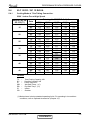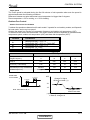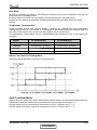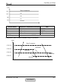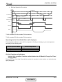
1
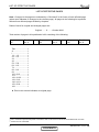
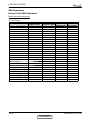
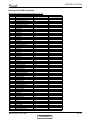
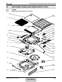
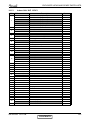
XLF DCI Series
Indoor Units
Outdoor Units
XLF 9
GC 9
XLF 12
GC 12
REFRIGERANT
R410A
HEAT PUMP
SM XLFDCI 1-A.1 GB
NOVEMBER – 2008
CONTENTS
LIST OF EFFECTIVE PAGES
LIST OF EFFECTIVE PAGES
Note: Changes in the pages are indicated by a “Revision#” in the footer of each effected page
(when none indicates no changes in the relevant page). All pages in the following list represent
effected/ non effected pages divided by chapters.
Dates of issue for original and changed pages are:
Original ....... 0 ........ October 2006
Total number of pages in this publication is 83 consisting of the following:
Page
No.
Revision
No. #
Page
No.
Revision
No. #
Page
No.
Revision
No. #
Title .......................1
A ...........................1
i .............................1
1-1 - 1-3 ................1
2-1 - 2-2 ................1
3-1 ........................1
4-1 ........................1
5-1 - 5-8 ................1
6-1 - 6-2 ................1
7-1 ........................1
8-1 - 8-2 ................1
9-1 ........................1
10-1-10-2 ..............1
11-1 .......................1
12-1-12-33 ............1
13-1-13-2 ..............1
14-1-14-11 ............1
15-1-15-8 ..............1
16-1 ......................1
●
Zero in this column indicates an original page.
* Due to constant improvements please note that the data on this service manual can be modified with out notice.
** Photos are not contractual.
A
CONTENTS
SM XLFDCI 1-A.1 GB
TABLE OF CONTENTS
Table of Contents
1.
INTRODUCTION ...................................................................................................1-1
2.
PRODUCT DATA SHEET ......................................................................................2-1
3.
RATING CONDITIONS ..........................................................................................3-1
4.
OUTLINE DIMENSIONS .......................................................................................4-1
5.
PERFORMANCE DATA & PRESSURE CURVES ................................................5-1
6.
SOUND LEVEL CHARACTERISTICS ..................................................................6-1
7.
ELECTRICAL DATA ..............................................................................................7-1
8.
WIRING DIAGRAMS .............................................................................................8-1
9.
ELECTRICAL CONNECTIONS .............................................................................9-1
10. REFRIGERATION DIAGRAMS .............................................................................10-1
11.
TUBING CONNECTIONS......................................................................................11-1
12. CONTROL SYSTEM .............................................................................................12-1
13. TROUBLESHOOTING ..........................................................................................13-1
14. EXPLODED VIEWS AND SPARE PARTS LISTS .................................................14-1
15. APPENDIX A .........................................................................................................15-1
SM XLFDCI 1-A.1 GB
i
INTRODUCTION
1.
INTRODUCTION
1.1
General
The new XLF DCI Inverter split wall mounted range comprise the RC (heat pump)
models, as follows:
• XLF 9 DCI
• XLF 12 DCI
The indoor XLF DCI units are available as LED display types, featuring esthetic design,
compact dimensions, and low noise operation.
1.2
Main Features
The XLF DCI series benefits from the most advanced technological innovations,
namely:
1.3
•
DC Inverter technology.
•
R410A models.
•
Microprocessor control.
•
Precharget refrigerant.
•
Infrared remote control with liquid crystal display.
•
Indoor centrifugal fan.
•
High COP.
•
DC Brush less fan motor.
•
Networking system connectivity.
•
Connection to Multi Split outdoor units
•
A dry contact for clock or power shedding functions (configurable).
•
Cooling operation at outdoor temperature down to -10ºC.
•
Heating operation at outdoor temperature down to -15ºC.
•
Low indoor and outdoor noise levels.
•
Easy installation and service.
Indoor Unit
The indoor unit is a wall mounted, and can be easily fitted to many types of residential
and commercials applications.
It includes:
•
Casing with air inlet and outlet grills.
•
A large-diameter centrifugal fan.
SM XLFDCI 1-A.1 GB
1-1
CONTENTS
INTRODUCTION
1.4
•
Coil with treated aluminum fins.
•
Motorized flaps.
•
Multi-speed motor with internal protection.
•
DC motor with internal protection.
•
Advanced electronic control box assembly.
•
Interconnecting wiring terminal block.
•
Mounting plate.
Filtration
The XLF DCI series presents one type of air filters:.
•
1.5
Easily accessible, and re-usable pre-filters (mesh).
Control
The microprocessor indoor controller, and an infrared remote control, supplied as
standard, provides complete operating function and programming. For further details
please refer to the Remote Control Manual, Appendix A.
1.6
Outdoor Unit
The XLF DCI outdoor units can be installed as floor or wall mounted units by using a
wall supporting bracket. The metal sheets are protected from corrosion allowing long life
resistance. All outdoor units are pre-charged. For further information please refer to the
Product Data Sheet, Chapter 2.
It includes:
1.7
•
Compressor mounted in a soundproofed compartment :
•
Axial fan.
•
Outdoor coil with hydrophilic louver fins for RC units.
•
Outlet air fan grill.
•
Service valves” flare” type connection.
•
Interconnecting wiring terminal block.
•
GC 9 R410A
•
GC 12 R410A
Tubing Connections
Flare type interconnecting tubing to be produced on site.
For further details please refer to the Installation Manual, APPENDIX A.
1-2
CONTENTS
SM XLFDCI 1-A.1 GB
INTRODUCTION
1.8
Accessories
Remote Control
RCW Wall Mounted Remote Control
The RCW remote control is mounted on the wall (RC-2,RC-3,RC-4), and controls the
unit either as an infrared remote control or as a wired controller. The wired controller
can control up to 10 Indoor units with the same program settings and adjustments.
For further details please refer to Optional Accessories.
1.9
Inbox Documentation
Each unit is supplied with its own installation, operation and remote control manuals.
1.10
Matching Table
1.10.1
R410A
INDOOR UNITS
OUTDOOR UNITS
SM XLFDCI 1-A.1 GB
MODEL
REFRIGER.
XLF 9
GC 9
R410A
√
GC 12
R410A
XLF 12
√
1-3
CONTENTS
PRODUCT DATA SHEET
2.
PRODUCT DATA SHEET
2.1
XLF 9 DCI
Model Indoor Unit
Model Outdoor Unit
XLF 9 DCI
GC 9 R410A
Installation Method of Pipe
Characteristics
Capacity (4)
Power input (4)
EER (Cooling) or COP(Heating) (4)
Energy efficiency class
V
Ph
Hz
A
Power supply
INDOOR
Rated current
Power factor
Prated (IDU)
Prated (IDU+ODU)
Starting current
Circuit breaker rating
Fan type & quantity
Fan speeds
Air flow (1)
External static pressure
Sound power level (2)
Sound pressure level (3)
Moisture removal
Condenstate drain tube I.D
Dimensions
Net Weight
Package dimensions
Packaged weight
Units per pallet
Stacking height
Refrigerant control
W
W
A
A
H/M/L
H/M/L
Min
H/M/L
H/M/L
WxHxD
WxHxD
RPM
m3/hr
Pa
dB(A)
dB(A)
l/hr
mm
mm
kg
mm
kg
units
units
OUTDOOR
Compressor type,model
Fan type & quantity
Fan speeds
Air flow
Sound power level
Sound pressure level (3)
Dimensions
Net Weight
Package dimensions
Packaged weight
Units per pallet
Stacking height
Refrigerant type
Standard charge
Additional charge
Connections between units
Operation control type
Heating elements (Option)
Others
Flared
Cooling
Heating
8530(4780-11600)
8530(5120-15360)
2.5(1.4-3.4)
2.5(1.5-4.5)
0.658(0.45-0.98)
0.625(0.48-1.53)
3.8
4.0
A
A
220-240
1
50
2.9
2.8
0.97
0.97
30
1600
10.5
15
Helicoid x 1
520/490/450
390/370/330
0
55/-/38/35/32
1
16
570*570*160
13.5
700*700*255
15.5
16
8levels
Electronical Expansion Valve
Units
Btu/hr
kW
kW
W/W
Single Rotary DC Inverter,Panasonic 5RS102XAB
H
H
H
H
WxHxD
WxHxD
In.(mm)
In.(mm)
m.
Propeller x 1
830
1780
61
51
795x610x290
38
970x650x394
42
9
3 levels
R410A
1.1
No need
1/4"(6.35)
3/8"(9.53)
Max.20
m.
Max.10
RPM
m3/hr
dB(A)
dB(A)
mm
kg
mm
kg
Units
units
kg(7.5m)
Liquid line
Suction line
Max.tubing length
Max.height
difference
Remote controll
kW
Airflow in ducted units;at nominal external static pressure.
Sound power in ducted units is measured at air discharge.
(3)
Sound pressure level measured at 1-meter distance from unit.
(4)
Rating conditions in accordance to ISO 5151 and ISO 13253 (for ducted units).
(1)
(2)
SM XLFDCI 1-A.1 GB
CONTENTS
2-1
PRODUCT DATA SHEET
2.2
XLF 12 DCI
Model Indoor Unit
Model Outdoor Unit
XLF 12 DCI
GC 12 R410A
Installation Method of Pipe
Characteristics
Capacity (4)
Power input (4)
EER (Cooling) or COP(Heating) (4)
Energy efficiency class
V
Ph
Hz
A
Power supply
INDOOR
Rated current
Power factor
Prated (IDU)
Prated (IDU+ODU)
Starting current
Circuit breaker rating
Fan type & quantity
Fan speeds
Air flow (1)
External static pressure
Sound power level (2)
Sound pressure level (3)
Moisture removal
Condenstate drain tube I.D
Dimensions
Net Weight
Package dimensions
Packaged weight
Units per pallet
Stacking height
Refrigerant control
W
W
A
A
H/M/L
H/M/L
Min
H/M/L
H/M/L
RPM
m3/hr
Pa
dB(A)
dB(A)
l/hr
mm
mm
kg
mm
kg
units
units
WxHxD
WxHxD
OUTDOOR
Compressor type,model
Fan type & quantity
Fan speeds
Air flow
Sound power level
Sound pressure level (3)
Dimensions
Net Weight
Package dimensions
Packaged weight
Units per pallet
Stacking height
Refrigerant type
Standard charge
Additional charge
Flared
Cooling
Heating
11940(4780-14000)
11940(5120-19100)
3.5(1.4-4.1)
3.5(1.5-5.6)
1.09(0.5-1.31)
0.969(0.53-1.94)
3.21
3.61
A
A
220-240
1
50
4.9
4.3
0.97
0.97
30
1800
10.5
15
Helicoid x 1
540/510/450
400/370/310
0
56/-/39/36/33
1.6
16
570*570*160
13.5
700*700*255
15.5
16
8 levels
Electronical Expansion Valve
Units
Btu/hr
kW
kW
W/W
Single Rotary DC Inverter,Panasonic 5RS102XAB
H
H
H
H
WxHxD
In.(mm)
In.(mm)
m.
Propeller x 1
830
1780
62
52
795x610x290
38.5
970x650x394
42.5
9
3 levels
R410A
1.2
No need
1/4"(6.35)
3/8"(9.53)
Max.20
m.
Max.10
RPM
m3/hr
dB(A)
dB(A)
mm
kg
mm
kg
Units
units
WxHxD
kg(7.5m)
Liquid line
Suction line
Connections between units Max.tubing length
Max.height
difference
Operation control type
Heating elements (Option)
Others
Remote control
kW
Airflow in ducted units;at nominal external static pressure.
Sound power in ducted units is measured at air discharge.
(3)
Sound pressure level measured at 1-meter distance from unit.
(4)
Rating conditions in accordance to ISO 5151 and ISO 13253 (for ducted units).
1)
(2)
2-2
CONTENTS
SM XLFDCI 1-A.1 GB
RATING CONDITIONS
3.
RATING CONDITIONS
Standard conditions in accordance with ISO 5151, ISO 13253 (for ducted units)
and EN 14511.
Cooling:
Indoor:
27oC DB 19oC WB
Outdoor: 35 oC DB
Heating:
Indoor:
20oC DB
Outdoor: 7oC DB 6oC WB
3.1
Operating Limits
3.1.1
R410A
Indoor
Cooling
Heating
Voltage
SM XLFDCI 1-A.1 GB
Outdoor
Upper limit
32oC DB 23oC WB
46oC DB
Lower limit
21oC DB 15oC WB
-10oC DB
Upper limit
27oC DB
24oC DB 18oC WB
Lower limit
10oC DB
-15oC DB -16oC WB
1PH
1PH 198 ÷ 264 V
CONTENTS
3-1
OUTLINE DIMENSIONS
4.
OUTLINE DIMENSIONS
4.1
Indoor Unit: XLF 9 DCI, XLF 12 DCI
4.2
Outdoor Unit: GC 9, GC 12
SM XLFDCI 1-A.1 GB
CONTENTS
4-1
PERFORMANCE DATA & PRESSURE CURVES
5.
PERFORMANCE DATA & PRESSURE CURVES
5.1
XLF 9 DCI / GC 9 R410A
5.1.1
Cooling Mode at 7.5m Tubing Connection.
230V : Indoor Fan at High Speed.
Entering Air DB
OD Coil(oC)
Data
TC
SC
PI
TC
SC
PI
TC
SC
PI
TC
SC
PI
TC
SC
PI
TC
SC
PI
TC
SC
PI
15
20
25
30
35
40
46
Entering Air WB/DB ID Coil(oC)
15/21
17/24
19/27
21/29
23/32
2.58
2.73
2.86
2.99
3.09
1.89
2.00
2.11
2.06
2.09
0.47
0.48
0.48
0.48
0.48
2.56
2.71
2.83
2.96
3.06
1.82
1.94
2.05
1.99
2.03
0.51
0.52
0.52
0.52
0.52
2.45
2.63
2.78
2.91
3.01
1.83
1.96
2.08
2.04
2.09
0.55
0.56
0.56
0.57
0.57
2.30
2.48
2.68
2.78
2.88
1.74
1.88
1.99
2.07
0.60
0.61
2.03
0.61
0.62
0.62
2.13
2.30
2.53
2.66
2.76
1.64
1.78
1.95
1.93
2.01
0.65
0.66
0.67
0.66
0.68
1.92
2.10
2.45
2.56
1.52
1.68
2.33
1.84
1.82
1.90
0.70
0.71
0.72
0.73
0.73
1.67
1.85
2.07
2.20
2.30
1.38
0.77
1.54
0.78
1.73
0.79
1.70
0.80
1.78
0.81
LEGEND
TC
SC
PI
WB
DB
ID
OD
–
–
–
–
–
–
–
Total Cooling Capacity, kW
Sensible Capacity, kW
Power Input, kW
Wet Bulb Temp., (oC)
Dry Bulb Temp., (oC)
Indoor
Outdoor
(1) Marked area is below standard operating limits. For operating in low ambient
conditions, refer to Optional Accessories (Chapter 15).
SM XLFDCI 1-A.1 GB
CONTENTS
5-1
PERFORMANCE DATA & PRESSURE CURVES
5.1.2
Heating Mode at 7.5m Tubing Connection.
230V : Indoor Fan at High Speed.
ENTERING AIR DB ID COIL(OC)
15
20
25
ENTERING WB
OD COIL(oC)
TH
Pl
TH
Pl
TH
Pl
-10
1.32
0.53
1.27
0.56
1.22
0.59
-7
1.42
0.54
1.37
0.57
1.32
0.60
-2
1.51
0.55
1.46
0.58
1.41
0.61
2
1.83
0.57
1.76
0.61
1.68
0.65
6
2.59
0.62
2.51
0.66
2.42
0.70
10
2.81
0.65
2.74
0.70
2.66
0.74
15
3.04
0.68
2.96
0.73
2.89
0.78
20
3.20
0.70
3.12
0.76
3.04
0.82
* the above chart includes the weighted deicing infleuence.
LEGEND
TH
PI
WB
DB
ID
OD
–
–
–
–
–
–
Total Heating Capacity, kW
Power Input, kW
Wet Bulb Temp., (oC)
Dry Bulb Temp., (oC)
Indoor
Outdoor
5.2
Capacity Correction Factor Due to Tubing Length
5.2.1
Cooling
3m
1.02
TOTAL TUBING LENGTH (One Way)
10m
15m
20m 25m 30m
7.5m
1
0.961
0.950
-------
40m
---
50m
---
* Minimum recommended tubing length between indoor and outdoor units is 3m.
5.2.2
Heating
3m
1.05
7.5m
1
TOTAL TUBING LENGTH (One Way)
10m
15m
20m 25m 30m
0.975
0.961
-------
40m
---
50m
---
* Minimum recommended tubing length between indoor and outdoor units is 3m.
5-2
CONTENTS
SM XLFDCI 1-A.1 GB
PERFORMANCE DATA & PRESSURE CURVES
5.3
Pressure Curves.
5.3.1
Cooling.
Suction Pressure VS.Outdoor Temp
Suction Pressure (Bar[g])
14.0
15/21(WB/DB ºC)
17/24(WB/DB ºC)
19/27(WB/DB ºC)
21/29(WB/DB ºC)
23/32(WB/DB ºC)
13.0
12.0
11.0
10.0
9.0
8.0
7.0
6.0
5.0
15
20
25
30
Outdoor Temp.(DB oC )
35
40
46
40
46
Discharge Pressure (Bar[g])
Discharge Pressure VS.Outdoor Temp
40
38
36
34
32
30
28
26
24
22
20
18
16
14
12
10
15/21(WB/DB ºC)
17/24(WB/DB ºC)
19/27(WB/DB ºC)
21/29(WB/DB ºC)
23/32(WB/DB ºC)
15
20
25
30
35
o
Outdoor Temp.(DB C )
SM XLFDCI 1-A.1 GB
CONTENTS
5-3
PERFORMANCE DATA & PRESSURE CURVES
5.3.2
Heating.
Suction Pressure VS.Outdoor Temp
Suction Pressure(Bar[g])
12.0
11.0
10.0
9.0
8.0
7.0
6.0
15 DB (ºC)
20 DB (ºC)
25 DB (ºC)
5.0
4.0
3.0
-10
-5
0
5
10
15
20
Outdoor Temp.( WB oC )
Discharge Pressure VS.Outdoor Temp
Discharge Pressure(Bar[g])
36
34
32
30
28
26
24
25 DB (ºC)
20 DB (ºC)
15 DB (ºC)
22
20
18
16
-10
5-4
-5
0
5
Outdoor Temp.( WB oC )
CONTENTS
10
15
20
SM XLFDCI 1-A.1 GB
PERFORMANCE DATA & PRESSURE CURVES
5.4
XLF 12 DCI / GC 12 R410A
5.4.1
Cooling Mode at 7.5m Tubing Connection.
230V : Indoor Fan at High Speed.
Entering Air DB
OD Coil(oC)
Data
TC
SC
PI
TC
SC
PI
TC
SC
PI
TC
SC
PI
TC
SC
PI
TC
SC
PI
TC
SC
PI
15
20
25
30
35
40
46
Entering Air WB/DB ID Coil(oC)
15/21
17/24
19/27
21/29
23/32
3.43
3.64
3.80
3.97
4.11
1.73
1.83
1.93
1.89
1.92
0.77
0.77
0.78
0.78
0.78
3.40
3.60
3.77
3.94
4.07
2.42
2.58
2.72
2.64
2.70
0.84
0.84
0.84
0.85
0.85
3.27
3.50
3.70
3.87
4.01
1.68
1.80
1.90
1.87
1.92
0.90
0.91
0.92
0.93
0.93
3.06
3.30
3.57
3.70
3.84
1.60
1.72
1.86
1.82
1.90
1.00
0.98
0.99
1.01
1.01
2.83
3.06
3.53
3.67
3.37
1.50
1.63
1.79
1.77
1.84
1.09
1.06
1.07
1.10
1.10
2.56
2.79
3.27
3.40
3.10
1.40
1.54
1.69
1.66
1.74
1.14
1.16
1.18
1.19
1.20
2.22
2.46
2.76
2.93
3.06
1.27
1.41
1.58
1.55
1.63
1.25
1.27
1.29
1.31
1.32
LEGEND
TC
SC
PI
WB
DB
ID
OD
–
–
–
–
–
–
–
Total Cooling Capacity, kW
Sensible Capacity, kW
Power Input, kW
Wet Bulb Temp., (oC)
Dry Bulb Temp., (oC)
Indoor
Outdoor
(1) Marked area is below standard operating limits. For operating in low ambient
conditions, refer to Optional Accessories (Chapter 15).
SM XLFDCI 1-A.1 GB
CONTENTS
5-5
PERFORMANCE DATA & PRESSURE CURVES
5.4.2
Heating Mode at 7.5m Tubing Connection.
230V : Indoor Fan at High Speed.
ENTERING AIR DB ID COIL(OC)
15
20
25
ENTERING WB
OD COIL(oC)
TH
Pl
TH
Pl
TH
Pl
-10
1.75
0.76
1.69
0.81
1.62
0.85
-7
1.89
0.78
1.82
0.82
1.75
0.87
-2
2.00
0.79
1.94
0.84
1.87
0.88
2
2.44
0.83
2.34
0.88
2.24
0.93
6
3.44
0.89
3.34
0.95
3.22
1.01
10
3.74
0.94
3.64
1.00
3.54
1.07
15
4.04
0.98
3.94
1.05
3.84
1.12
20
4.25
1.01
4.15
1.09
4.04
1.18
* the above chart includes the weighted deicing infleuence.
LEGEND
TH
PI
WB
DB
ID
OD
–
–
–
–
–
–
Total Heating Capacity, kW
Power Input, kW
Wet Bulb Temp., (oC)
Dry Bulb Temp., (oC)
Indoor
Outdoor
5.5
Capacity Correction Factor Due to Tubing Length
5.5.1
Cooling
3m
1.02
7.5m
1
TOTAL TUBING LENGTH (One Way)
10m
15m
20m 25m 30m
0.961
0.948
-------
40m
---
50m
---
* Minimum recommended tubing length between indoor and outdoor units is 3m.
5.5.2
Heating
3m
1.05
7.5m
1
TOTAL TUBING LENGTH (One Way)
10m
15m
20m 25m 30m
0.975
0.963
-------
40m
---
50m
---
* Minimum recommended tubing length between indoor and outdoor units is 3m.
5-6
CONTENTS
SM XLFDCI 1-A.1 GB
PERFORMANCE DATA & PRESSURE CURVES
5.6
Pressure Curves.
5.6.1
Cooling.
Suction Pressure VS.Outdoor Temp
Suction Pressure (Bar[g])
14.0
15/21(WB/DB ºC)
17/24(WB/DB ºC)
19/27(WB/DB ºC)
21/29(WB/DB ºC)
23/32(WB/DB ºC)
13.0
12.0
11.0
10.0
9.0
8.0
7.0
6.0
5.0
15
20
25
30
Outdoor Temp.(DB oC )
35
40
46
40
46
Discharge Pressure (Bar[g])
Discharge Pressure VS.Outdoor Temp
40
38
36
34
32
30
28
26
24
22
20
18
16
14
12
10
15/21(WB/DB ºC)
17/24(WB/DB ºC)
19/27(WB/DB ºC)
21/29(WB/DB ºC)
23/32(WB/DB ºC)
15
20
25
30
35
Outdoor Temp.(DB oC )
SM XLFDCI 1-A.1 GB
CONTENTS
5-7
PERFORMANCE DATA & PRESSURE CURVES
5.6.2
Heating.
Suction Pressure VS.Outdoor Temp
Suction Pressure(Bar[g])
11.0
10.0
9.0
8.0
7.0
6.0
15 DB (ºC)
20 DB (ºC)
25 DB (ºC)
5.0
4.0
3.0
-10
-5
0
5
10
15
20
Outdoor Temp.( WB oC )
Discharge Pressure VS.Outdoor Temp
Discharge Pressure(Bar[g])
38
36
34
32
30
28
26
24
25 DB (ºC)
20 DB (ºC)
15 DB (ºC)
22
20
18
16
-10
5-8
-5
0
5
Outdoor Temp.( WB oC )
CONTENTS
10
15
20
SM XLFDCI 1-A.1 GB
SOUND LEVEL CHARACTERISTICS
6.
SOUND LEVEL CHARACTERISTICS
6.1
Sound Pressure Level
Unit
1m
Wall
Mic.
Figure 1
6.2
Sound Pressure Level Spectrum (Measured as Figure 1)
XLF 12 DCI
-70NC
-60NC
-50NC
-40NC
-30NC
APPROXIMATE
THRESHOLD OF
HEARING FOR
CONTINUOUS
NOISE
-20NC
MICRO BAR0.002 dB re , OCTAVE BAND SOUND PRESSURE LEVEL
MICRO BAR0.002 dB re , OCTAVE BAND SOUND PRESSURE LEVEL
XLF 9 DCI
Hz, BAND CENTER FREQUENCIES
FAN SPEED
-70NC
-60NC
-50NC
-40NC
-30NC
APPROXIMATE
THRESHOLD OF
HEARING FOR
CONTINUOUS
NOISE
-20NC
Hz, BAND CENTER FREQUENCIES
LINE
HI
ME
LO
SM XLFDCI 1-A.1 GB
CONTENTS
6-1
SOUND LEVEL CHARACTERISTICS
6.3
Outdoor units
Unit
1m
Mic.
Ground
Figure 2
6.4
6-2
Sound Pressure Level Spectrum (Measured as Figure 2)
GC 9 Cooling
GC 9 Heating
GC 12 Cooling
GC 12 Heating
CONTENTS
SM XLFDCI 1-A.1 GB
ELECTRICAL DATA
7.
ELECTRICAL DATA
7.1
Single Units
MODEL
XLF 9 DCI
XLF 12 DCI
To indoor
To indoor
1PH-230V-50Hz
1PH-230V-50Hz
Max Current, (A)
10.0
10.0
Circuit Breaker,(A)
15.0
15.0
Power Supply Wiring.
(No. x Cross Section mm2)
3 x 1.5 mm2
3 x 1.5 mm2
Interconnecting Cable ST Model
(No. x Cross Section mm2)
4 x 1.5 mm2
4 x 1.5 mm2
Power Supply
NOTE
Power wiring cord should comply with local lows and electrical
regulations requirements.
SM XLFDCI 1-A.1 GB
CONTENTS
7-1
BRN
RED
N
W
P503
BLK
L COM
P101
1
2
3
4
JP602
2
5
6
6
5
4
P301
3
2
1
5
FG
6
CONTENTS
N/3
L/4
C/5
3
P605
EEV
4
1
2
2
P604
2
P602
1
2
OCT
P606
1
HST
TO AC MAINS
(FOR POWER SOURCE
FROM ODU)
1
P603
1
CTT
2
BLUE
RED
GND
To metal sheet
C P19
N P17
L P13
F1 FUSE
P10P15P3P16P14
DC MOTOR M
M
P32
M
P11 P27
M
STEP MOTOR
M
Main Board
P33
Optional
ALARMON/OFFRCW/uBMS
P22
IONIZER
P2
P8
P1
PD/PS
ICT
RAT
ICTE
P5(WH)P4(RD)P20(BU)
P6 P30
FLASH
PROGRAMING J2J7J9
SW1
P7 Megatool
INDOOR UNIT CIRCUIT DIAGRAM
P12
T3.15AL250V
EARTH
YELLOW/GREEN
BROWN
C
BLUE
1
1
P103
OAT
N
BROWN
RED
EARTH
P105
Y/G
2
P102
(OPTIONAL)
OFAN
VDC
BASE
VCC
HEATER
L
FERRITE CORE
FUSE
ODU CONTROLLER PCBA
V
U
P501 P502
VALVE
VSP
REVERSE
GND
COMP
YELLOW/GREEN
SM XLFDCI 1-A.1 GB
RD
BK
OG
YE
BU
OUTDOOR UNIT CIRCUIT DIAGRAM
LEGEND:
TWIN - TWIN WIRE CABLE
BLUE
YEW - YELLOW,RD - RED,BLU -
ICTE:Indoor Coil Temperature
WHT - WHITE,BN - BROWN,BLK Evaporator
BLACK
RAT:Room Air Temperature
ICT:Indoor coil temperature
BOARD
DISPLAY
WIRING DIAGRAMS
8.
WIRING DIAGRAMS
8.1
Units: XLF 9 DCI, XLF 12 DCI / GC 9, GC 12 R410A
POWER SUPPLY
8-1
ELECTRICAL CONNECTIONS
9.
ELECTRICAL CONNECTIONS
9.1
XLF 9 / GC 9, XLF 12 / GC 12 R410A
Indoor unit
C L
5 4
Outdoor unit
C L
5 4
SM XLFDCI 1-A.1 GB
CONTENTS
9-1
REFRIGERATION DIAGRAMS
10.
REFRIGERATION DIAGRAMS
10.1
Heat Pump Models
10.1.1
XLF 9 DCI, XLF 12 DCI R410A
10.1.1a
Cooling Mode
OUTDOOR UNIT
INDOOR UNIT
Sensor
Sensor
Valves
Reverse
valve
Flared
connection
Indoor coil
EEV
Outdoor coil
10.1.1b
Strainer
Strainer
Heating Mode
OUTDOOR UNIT
INDOOR UNIT
Sensor
Sensor
Valves
Reverse
valve
Indoor coil
EEV
Outdoor coil
Strainer
SM XLFDCI 1-A.1 GB
Flared
connection
Strainer
CONTENTS
10-1
TUBING CONNECTIONS
11.
TUBING CONNECTIONS
TUBE (Inch)
¼”
⅜”
½”
⅝”
¾”
11-13
13-20
11-13
40-45
13-20
11-13
60-65
18-25
11-13
70-75
18-25
11-13
80-85
40-50
11-13
TORQUE (Nm)
Flare Nuts
Valve Cap
Service Port Cap
1.
2.
3.
4.
5.
6.
7.
8.
Valve Protection Cap-end
Refrigerant Valve Port (use Allen wrench to open/close)
Valve Protection Cap
Refrigerant Valve
Service Port Cap
Flare Nut
Unit Back Side
Copper Tube
When the outdoor unit is installed above the indoor unit an oil trap is required every 5m along the suction
line at the lowest point of the riser. Incase the indoor unit is installed above the outdoor, no trap is
required.
SM XLFDCI 1-A.1 GB
CONTENTS
11-1
CONTROL SYSTEM
12
CONTROL SYSTEM
12.1
General Functions and Operating RulesThe DCI software parametric.
All the model dependent parameters are shown in Blue color and with Italic style [parameter].
The parameters values are given in the last section of this control logic chapter of the service
manual.
System Operation Concept
The control function is divided between indoor and outdoor unit controllers. Indoor unit is the system
‘Master’, requesting the outdoor unit for cooling/heating capacity supply. The outdoor unit is the
system ‘Slave’ and it must supply the required capacity unless it enters into a protection modeavoiding
it from supplying the requested capacity.
The capacity request is transferred via indoor to outdoor communication, and is represented by
aparameter called ‘NLOAD’. NLOAD is an integer number with values between 0 and 127, and
itrepresents the heat or cool load felt by the indoor unit.
Compressor Frequency Control
NLOAD setting
The NLOAD setting is done by the indoor unit controller, based on a PI control scheme.
The actual NLOAD to be sent to the outdoor unit controller is based on the preliminary LOAD
calculation, the indoor fan speed, and the power shedding function.
NLOAD limits as a function of indoor fan speed:
Indoor Fan Speed Maximum NLOAD Cooling Maximum NLOAD Heating
IndoorFan Speed
Maximum NLOAD Cooling
Low
Medium
High
Turbo
Auto
Maximum NLOAD Heating
MaxNLOADIF1C
MaxNLOADIF2C
MaxNLOADIF3C
MaxNLOADIF4C
MaxNLOADIF5C
MaxNLOADIF1H
MaxNLOADIF2H
MaxNLOADIF3H
MaxNLOADIF4H
MaxNLOADIF5H
NLOAD limits as a function of power shedding:
Mode
Power Shedding OFF
Power Shedding ON
Cooling
Heating
No limit
No limit
Nominal Cooling
Nominal heating
Target Frequency Setting
Target Frequency Setting for GC 9 / 12
The compressor target frequency is a function of the NLOAD number sent from the indoorcontroller
and the outdoor air temperature.
Basic Target Frequency Setting:
12-1
SM XLFDCI 1-A.1 GB
CONTENTS
CONTROL SYSTEM
NLOAD
Target Frequency
127
Maximum Frequency
10<NLOAD<127
Interpolated value between minimum and maximum frequency
10
0
Minimum frequency
Compressor is sXLFped
Target frequency limits as a function of outdoor air temperature (OAT):
OAT Range
Cooling Mode limits
OAT < 6
Heating Mode limits
No limit
6 ≤ OAT < 15
MaxFreqAsOATC
15≤ OAT<28
28≤ OAT
MaxFreqAsOAT1H
MaxFreqAsOAT2H
No limit
Frequency Changes Control
When the unit is running normally , the compressor frequency change rate is 1 Hz/sec.
Compressor Starting Control
Compressor starting control for GC 9 / 12
Step3
Step2
Step1
1
Minute
1
Minute
Time
Min 10 Minutes
Minimum On and Off Time
3 minutes
Indoor Fan Control
8 Indoor fan speeds are determined for each model. 4 speeds for cool/dry/fan modes and 4 speeds
for heat mode.
When user sets the indoor fan speed to a fixed speed (Low/ Medium/ High), unit will operate constantly
at set speed.
When Auto Fan is selected, indoor unit controller can operate in all speeds. The actual speed is set
according to the cool/heat load.
12-2
SM XLFDCI 1-A.1 GB
CONTENTS
CONTROL SYSTEM
Turbo Speed
The Turbo speed is activated during the first 30 minutes of unit operation when auto fan speed is
selected and under the following conditions:
Difference between set point and actual room temperature is bigger than 3 degrees.
Room temperature > 22 for cooling, or < 25 for heating.
Outdoor Fan Control
Outdoor Fan Control for DCI25/35
7 outdoor fan speeds are determined for each model. 3 speeds for cool and dry modes, and 3speeds
for heat mode, and a very low speed.
Outdoor fan speed is a function of compressor frequency and outdoor air temperature (OAT).
4 routines for fan control are determined. The control routine selection depends on operationmode,
compressor speed, outdoor air temperature (OAT) and heat sink temperature (HST).
Routine
Conditions
Heating with OAT < 15℃ or
Cooling with OAT > 20℃, or Faulty OAT
Cooling with 20℃ > OAT > 7℃
Cooling with 7℃ > OAT
Heating with OAT > 15℃
A
B
C
D
OFAN Speed
Compressor
Target Frequency
Routin
A
Routin
B
Routin
C
Routin
D
Freq=0
OFF
OFF
OFF
OFF
10 ≤ Freq < OFLowFreq
Low
Low
VL
Low
Medium
Low
VL
Low
High
Low
Low
Medium
OFLowFreq ≤ Freq< OFMedFreq
OFMedFreq≤ Freq
OFAN State
at Cool Mode
HST
3 Degrees
A
Change To Higher
OFAN Cool state (*1)
3 Degrees
B
50
C
7
20 OAT
45
Note: Periorities A >B >C
Change To lower
OFAN Cool state
(*1) If
State C, change to B
If State B, change to A
12-3
SM XLFDCI 1-A.1 GB
CONTENTS
CONTROL SYSTEM
When compressor is switched to OFF and the heat sink temperature is above 55 degrees, the
outdoor fan will remain ON in low speed for up to 3 minutes.
EEV (Electronic Expansion Vavle) Control
EEV Control for GC 9 / 12
EEV opening is defined as EEV = EEVOL + EEVCV
EEVOL is the initial EEV opening as a function of the compressor frequency, operation mode, unit
model and capacity.
EEVCV is a correction value for the EEV opening that is based on the compressor temperature.
During the first 5 minutes of compressor operation EEVCV = 0.
Once the first 5 minutes are over, the correction value is calculated as follow: EEVCV(n) = EEVCV(n-1)
+ EEVCTT
EEVCTT is the correction based on the compressor temperature. A target compressor temperature is
set depending on frequency and outdoor air temperature, and the actual compressor temperature is
compared to the target temperature to set the required correction to the EEV
opening.
RV(Reversing Valve) Control
Reversing valve is on in heat mode.
Switching of RV state is done only after compressor is off for over 3 minutes.
Ionizer Control
Ionizer is on when unit is on ,AND indoor fan is on ,AND Ioniser power switch is on.
Base Heater Control
The base heater will be working only when RV is “ON” according to the following graph:
Base
Heater
OFF
ON
0
2
OAT
When OAT is faulty the base heater will be “ON” continuously in HEAT mode.
Fan Mode
In high/ medium/ low indoor fan user setting, unit will operate fan in selected speed.
In AutoFan user setting, fan speed will be adjusted automatically according to the difference between
actual room temperature and user set point temperature.
Cool Mode
NLOAD is calculated according to the difference between actual room temperature and user set
point temperature by fuzzy control.
In high/ medium/ low indoor fan user setting, unit will operate fan in selected speed.
In AutoFan user setting, fan speed will be adjusted automatically according to the calculated
NLOAD.
12-4
SM XLFDCI 1-A.1 GB
CONTENTS
CONTROL SYSTEM
Heat Mode
NLOAD is calculated according to the difference between actual room temperature and user set
point temperature by fuzzy control.
In high/ medium/ low indoor fan user setting, unit will operate fan in selected speed.
In AutoFan user setting, fan speed will be adjusted automatically according to the calculated
NLOAD.
Temperature Compensation
In wall mounted, ducted, and cassette models, 3 degrees are reduced from room temperature
reading (except when in I-Feel mode), to compensate for temperature difference between high and
low areas in the heated room, and for coil heat radiation on room thermistor.
The temperature compensation can be enabled/disabled by shortening of J2 on the indoor unit
Controller
Model
J2 Shorted(ON)
J2 Opened(OFF)
Wall mounted
Compensation Disabled
Compensation Enabled
Cassette
Compensation Enabled
Compensation Disabled
Ducted
Compensation Enabled
Compensation Disabled
Floor/Ceiling
Compensation Disabled
Compensation Enabled
Indoor Fan Control in Heating Mode
Indoor fan speed depends on the indoor coil temperature:
Auto Cool/Heat Mode
When in auto cool heat mode unit will automatically select between cool and heat mode according to
the difference between actual room temperature and user set point temperature (.T).
Unit will switch from cool to heat when compressor is off for 3 minutes, and .T < -3.
Unit will switch from heat to cool when compressor is off for 5 minutes, and .T < -3.
12-5
SM XLFDCI 1-A.1 GB
CONTENTS
CONTROL SYSTEM
Dry Mode
As long as room temperature is higher then the set point, indoor fan will work in low speed and
compressor will work between 0 and MaxNLOADIF1C Hz.
When the room temperature is lower than the set point, compressor will be switched OFF and
indoor fan will cycle 3 minutes OFF, 1 minute ON.
Protections
There are 5 protection codes.
Normal (Norm) – unit operate normally.
SXLF Rise (SR) – compressor frequency can not be raised but does not have to be decreased.
HzDown1 (D1) – Compressor frequency is reduced by 2 to 5 Hz per minute.
HzDown2 (D2) – Compressor frequency is reduced by 5 to 10 Hz per minute.
SXLF Compressor (SC) – Compressor is sXLFped.
Indoor Coil Defrost Protection
Trend
Min(ICT,ICTE)
< -2
[-2, 0)
[0, 2)
[2, 4)
[4, 6)
[6, 8]
>8
Fast Increasing
Increasing
No Change
SC
D1
SR
SR
Norm
Norm
SC
D1
SR
SR
Norm
Norm
SC
D2
D1
SR
SR
Norm
Norm
Decreasing Fast Decreasing
SC
D2
D2
D1
SR
SR
SC
D2
D2
D2
D1
SR
Indoor Coil Overheating Protection
ICT
ICT Trend
Fast Decreasing
Decreasing
No Change
Increasing
Fast Increasing
>62
[60, 62)
SC
D1
SC
D1
SC
D2
SC
D2
SC
D2
[55, 60)
SR
SR
D1
D2
D2
[52, 55)
SR
SR
SR
D1
D2
[48, 52)
Norm
Norm
SR
SR
D1
[45, 48)
I<45
Norm
Norm
Norm
Norm
SR
SR
Compressor Overheating Protection
Compressor Overheating Protection for GC 9 / 12
Compressor temperature can be in one of 5 control zones (4 in protection, and 1 normal),
according to the following chart.
12-6
SM XLFDCI 1-A.1 GB
CONTENTS
CONTROL SYSTEM
CTT
Stop-Compressor
105
P3
102
P2
98
P1
94
Normal
Control Status
Compressor Temperature Increases
Else
P1
Normal
SXLF Rise
P2
HzDown 1
SXLF Rise
P3
HzDown 2
HzDown 1
SXLF Compressor
SXLF Compressor
Compressor Over Current Protection Only For DCI25/35
CCR
Stop-Compresor
CCROC4
HzDown2
CCROC3
HzDown1
CCROC2
Stop-Rise
CCROC1
Normal
12-7
SM XLFDCI 1-A.1 GB
CONTENTS
CONTROL SYSTEM
Heat Sink Overheating Protection
Heat Sink Overheating Protection For GC 9 / 12
HST Trend
HST
Fast Decreasing Decreasing
No Change
Increasing Fast Increasing
≥ 90
SC
SC
SC
SC
SC
[85, 90)
D1
D1
D2
D2
D2
[82, 85)
SR
SR
D1
D2
D2
[80, 82)
SR
SR
SR
D1
D1
[78 , 80)
Norm
Norm
Norm
SR
SR
< 78
Norm
Outdoor Coil Deicing Protection
Outdoor coil Deicing Protection For GC 9 / 12
● Entering Deicing Conditions
Deicing operation will start when either one of the following conditions exist:
Case 1: OCT < OAT – 8 AND TLD > DI
Case 2: OCT < OAT – 12 AND TLD > 30 minutes.
Case 3: OCT is Invalid AND TLD > DI
Case 4: Unit is just switched to STBY AND OCT < OAT – 8
Case 5: NLOAD = 0 AND OCT < OAT -8
Case 6: OCT<-19 AND TLD>60 minutes
All this condition will exist during 10 seconds
OCT – Outdoor Coil Temperature
OAT – Outdoor Air Temperature
TLD – Time from Last Deicing
DI – Deicing Interval (Time Interval Between Two Deicing)
Deicing interval time when compressor is first started in heat mode, is 10 minutes if OCT < -2, and
is 40 minutes in other cases.
Deicing interval time is changed (increased/ decreased in 10 minutes steps) as a function of
deicing time. If deicing time is shorter then former deicing time, the deicing interval time will be
increased. If deicing time is longer then former deicing time, the deicing interval time will be
decreased.
12-8
SM XLFDCI 1-A.1 GB
CONTENTS
CONTROL SYSTEM
●
Deicing Operation Procedure
OCT
12
0
T h re s h o ld
COMP
ON
T1
T2
DT
m a x. 1 2 m in u te s
D e ic e F re q C h R V
RV
HEAT
COOL
O FAN
T1
T3
T3
ON
OFF
EEV
E E V D e ic e rO p e n
Any
T1=60 secondes;T2=36 secondes;T3=6 secondes
T1=50 secondes;T2=36 secondes;T3=6 secondes
Operating the Unit from Mode Button (On displayer)
Forced operation allows to start, sXLF and operate in Cooling or Heating, in pre-set temperature
according to the following table:
Forced operation Mode
Cooling
Heating
Pre-set Temperature
20℃
28℃
On Unit Controls and Indicators
Indoor Unit controller Controls and Indicatiors for All Models Except for Floor/
Ceiling model
During OFF, Fan, Cool, Heat, Dry, and Auto modes (for operation in other modes, see at the relevant
spec paragraph):
12-9
SM XLFDCI 1-A.1 GB
CONTENTS
CONTROL SYSTEM
STAND BY
z
INDICATION
Lights up when the Air Conditioner is connected to power and
ready to receive the R/C commands
z
STBY will be indicately by the following illumination (purple color):
LED
Duty Cycle (%)
‘Unit Mode’ Heat (Red)
50
‘Unit Mode’ Cool (Blue)
50
The combined color is purple (it’s not red and not blue)
OPERATION INDICATION
z
‘Unit Mode’ Cool Lights up in blue color during Cool, Dry, Fan, or
Auto modes. Even though the mode can be changed automatically
from Auto Cool to Auto Heat, the ‘Unit Mode’ Cool will light on.
z
‘Unit Mode’ Heat Lights up in Red color during heat mode. It will
not light up during Auto Heat mode.
z
Blinks continuously during protections (accoring to the relevant
spec section). During heating the ‘Unit Mode’ Heat blinks. In cool,
Dry, Fan, or Auto modes the ‘Unit Mode’ Cool blinks. The duty
cycle illumination in protection mode 100%.
z
The Red or Blue LEDS illuminates according to the following
Profile each time receiving an RC command.
z
Time (sec)
Duty Cycle (%)
0-2
100
2-4
90
4-6
80
6-8
70
8-10
60
>10
50
The ‘Unit Mode’ LED will indicate the relevant mode (heat and
Cool/Dry/Fan/Auto) under any system Trigger for mode change:
Interal timer
Timer-to-on command
12-10
SM XLFDCI 1-A.1 GB
CONTENTS
CONTROL SYSTEM
Presence detector
Remote controller
ICOM-X command
Mode Button
ESF/INOIZER INDICATOR
z
Lights up during ESF/ ionizer operation.
TIMER INDICATOR
z
Lights up during Timer and Sleep operation.
FILTER INDICATOR
z
The filer LED never lights up(even when the filer needs to be
cleaned).
COOLING INDICATOR
z
Lights up only during diagnostics (changing mode be pressing the
Mode Button does not turn on this LED).
HEATING INDICATOR
z
Lights up only during diagnostics (changing mode by pressing the
Mode Button does not turn on this LED).
MODE
z
Every short pressing , the next operation mode is selected, in this
BUTTON(COOL/HEAT/OF
SB ĺ Cool Mode ĺ Heat Mode ĺ SB ĺ …
order :
F)
RESET BUTTON
z
In long pressing the system enters into diagnostic mode.
z
For short pressing enables/disables the buzzer announcer: enable
ĺdisable…where the default value is enable.
z
In long pressing system enters set up mode (if in SB).
Outdoor Unit controller Indicatiors
Unit has three LED’s.
SB LED is ON when power is ON (230 VAC, even when no communication).
STATUS LED is ON when COMP is ON, and Blinks according to diagnostics mode definitions
when either fault or protection occurs.
FAULT LED Blinks according to diagnostics mode definitions when either fault or protection
occurs.
Jumper Settings
Indoor Unit Controller
Definations:
Logic Input
Jumper (J)
DIP switch (D)
0
Open(Disconnected)
OFF
1
Close(Connected)
ON
12-11
SM XLFDCI 1-A.1 GB
CONTENTS
CONTROL SYSTEM
Self Test Jumper(J1)
Jumper for production line check.
DIP Switch Settings
●
Compensation setting
This setting activates the compensation to the return air temperature in heating mode. For indoor unit
like cassette, the DIP switch J2 should be ON.
Compensation
J2(DIP1)
Activated (factory setting)
Deactivated
ON
OFF
●
Unit model setting (Factory setting)
The unit model setting should be in accordance with the unit model on the nameplate. The unit
operating parameters will be improper with wrong settings.
Unit model (Capacity)
J7(DIP2)
2.5kW model
3.5kW model
OFF
ON
●
Presence Detector/Power Shedding Selection
Select the functions of dry contact PD/PS by setting the Dip switch J9
Selection
J9(DIP3)
Presence Detector
Power Shedding
OFF
ON
Dry Contacts
● Alarm Output
The Alarm Output dry contact will be on (closed), when a predefined set faults occur.
The fault set is defined under diagnostics section.
The alarm output will be off (open), when the predefined fault is cleared.
12-12
SM XLFDCI 1-A.1 GB
CONTENTS
CONTROL SYSTEM
The indoor alarm outputs are defined according to the following table:
No
Problem
AO
5
4
3
2
1
1
ICT is disconnected
Yes
0
0
0
0
1
2
ICT is shorted
Yes
0
0
0
1
0
3
RAT is disconnected
Yes
0
0
0
1
1
4
RAT is shorted
Yes
0
0
1
0
0
5
Reserved (for MSMP used as RGT fault)
No
0
0
1
0
1
6
ICTE shorted/disconnected (when enabled)
Yes
0
0
1
1
0
7
Undefined IDU family/model
Yes
0
0
1
1
1
8
No Communication
Yes
0
1
0
0
0
9
No Encoder
No
0
1
0
0
1
10
Reserved
No
0
1
0
1
0
11
Outdoor Unit Fault
No
0
1
0
1
1
…
Reserved
No
17
Defrost protection
No
1
0
0
0
1
18
Deicing Protection
No
1
0
0
1
0
19
Outdoor Unit Protection
No
1
0
0
1
1
20
Indoor Coil HP Protection
No
1
0
1
0
0
21
Overflow Protection
Yes
1
0
1
0
1
22
Reserved
No
24
EEPROM Not Updated
No
1
1
0
0
0
25
Bad EEPROM
No
1
1
0
0
1
26
Bad Communication
No
1
1
0
1
0
27
Using EEPROM data
No
1
1
0
1
1
28
Model A
No
1
1
1
0
0
29
Model B
No
1
1
1
0
1
30
Model C
No
1
1
1
1
0
31
Model D
No
1
1
1
1
1
Notes:
1. Only one code is shown. Order of priority is lower to the higher number. Diagnostics is
continuously ON as long power is on.
XLF DCI
2. The following case describes the LEDs used to present diagnostics and the indication:
Cool LED (Diag- Heat LED (DiagIndoor Diagnostics
nostics) Replaced nostics) Replaced
indicated by
BY
BY
Outdoor Diagnostics
indicated by
‘Unit Mode’ cool is on ‘Unit Mode’ heat blinks
Use Cool LED (Do Use Heat LED (Do
(100%) during indoor during Outdoor diagnot replace)
not replace)
diagnostics.
nostics.
12-13
SM XLFDCI 1-A.1 GB
CONTENTS
CONTROL SYSTEM
The outdoor alarm outputs are defined in the following way:
No
1
2
3
4
5
6
7
8
9
10
11
12
13
14
15
16
17
18
20
21
22
23
24
25
26
27
28
29
30
31
Problem
OCT is disconnected
OCT is shorted
CTT is disconnected
CTT is shorted
HST is disconnected (when enabled)
HST is shorted (when enabled)
OAT is disconnected (when enabled)
OAT is shorted (when enabled)
TSUC is disconnected (when enabled)
TSUC is shorted (when enabled)
IPM Fault
Bad EEPROM
DC under voltage
DC over voltage
AC under voltage
Mismatch between IDU & ODU models
No Communication
Reserved
Heat sink Over Heating
Deicing
Compressor Over Heating
Compressor Over Current
No OFAN Feedback
OFAN locked
Compressor Lock
Bad Communication
Missing ODU configuration
Undefined ODU Model
For future use
Operation condition is exceeded
AO
5
4
3
2
1
Yes
Yes
Yes
Yes
Yes
Yes
Yes
Yes
Yes
Yes
Yes
No
Yes
Yes
Yes
Yes
Yes
No
No
No
No
No
No
Yes
Yes
No
Yes
Yes
No
Yes
0
0
0
0
0
0
0
0
0
0
0
0
0
0
0
1
1
1
1
1
1
1
1
1
1
1
1
1
1
1
0
0
0
0
0
0
0
1
1
1
1
1
1
1
1
0
0
0
0
0
0
0
1
1
1
1
1
1
1
1
0
0
0
1
1
1
1
0
0
0
0
1
1
1
1
0
0
0
1
1
1
1
0
0
0
0
1
1
1
1
0
1
1
0
0
1
1
0
0
1
1
0
0
1
1
0
0
1
0
0
1
1
0
0
1
1
0
0
1
1
1
0
1
0
1
0
1
0
1
0
1
0
1
0
1
0
1
0
0
1
0
1
0
1
0
1
0
1
0
1
● Unit ON Output
The ‘On/Off status’ dry contact will be on (closed), when the indoor mode is not STBY.
If the indoor mode is STBY mode, the ‘On/Off status’ will be off (open).
● PD/PS(Presence Detector/Power Shedding) ther
Function
J9=OFF
J9=ON
Presence Detector Connection
Power Shedding Function
Contact=open
Contact=short
No limit
No limit
Force to STBY
Limit NLOAD
Outdoor Unit Controller
JP9 Dip switch setting
ODU Model Selection
ODU3(DIP1)
ODU2(DIP1)
ODU1(DIP1)
ODU0(DIP1)
ODU Model
OFF
OFF
OFF
OFF
OFF
OFF
OFF
OFF
ON
OFF
ON
OFF
Reserved
A (Single GC 9)
B (Single DCI35)
12-14
SM XLFDCI 1-A.1 GB
CONTENTS
CONTROL SYSTEM
Test Mode
Entering Test Mode
System can enter Test mode in two ways:
Automatically when the following conditions exists for 30 minutes continuously:
Mode = Cool, Set point = 16, Room temperature = 27(+1/-2), Outdoor temperature = 35(+2/-1) Or
Mode = Heat, Set point = 30, Room temperature = 20±1, Outdoor temperature = 7±(+1/-2) Manually
when entering diagnostics with the following settings:
Mode = Cool, Set point = 16
Mode = Heat, Set point = 30
Unit Operation in Test Mode
In test mode, the unit will operate in fixed settings according to the indoor fan speed setting:
Indoor FAN Speed Setting
Unit Setting
Low
Minimum Capacity Setting
Turbo
Nominal Capacity Setting
Auto
Maximum Capacity Setting
During test mode, protections are disabled, except for XLF compressor status.
12-15
SM XLFDCI 1-A.1 GB
CONTENTS
CONTROL SYSTEM
SW Parameters
Indoor Units SW Parameters
Model dependent parameters
XLF DCI Family
IFVLOWC
IFLOWC
IFMEDC
IFHIGHC
IFTURBOC
IFVLOWH
IFLOWH
IFMEDH
IFHIGHH
IFTURBOH
Cap .Group
NomLoadC
NomLoadH
MaxNLOADIF1C
MaxNLOADIF2C
MaxNLOADIF3C
MaxNLOADIF4C
MaxNLOADIF5C
IFAN_SPEED_COMP0_C
IFAN_SPEED_COMP1_C
IFAN_SPEED_COMP2_C
IFAN_SPEED_COMP3_C
IFAN_SPEED_COMP0_H
IFAN_SPEED_COMP1_H
IFAN_SPEED_COMP2_H
IFAN_SPEED_COMP3_H
ModelEnable
A (XLF 9 DCI)
B (XLF 12 DCI)
400
450
490
520
570
400
450
490
520
620
0
46
43
47
70
127
127
127
0
0
0
0
0
0
0
0
1
400
450
510
540
590
400
450
510
590
820
1
69
56
42
59
127
127
127
0
0
0
0
0
0
0
0
1
12-16
C
(Reserved)
D
(Reserved)
SM XLFDCI 1-A.1 GB
CONTENTS
CONTROL SYSTEM
Outdoor Units SW Parameters
Model dependent parameters for GC 9 / GC 12
Name
1
2
3
4
5
6
7
8
9
10
11
12
13
14
15
16
17
18
19
20
21
22
23
24
25
26
27
28
29
30
31
32
33
34
35
36
37
38
39
40
41
42
43
44
45
46
47
48
49
50
51
52
53
54
55
56
57
58
59
60
61
62
63
64
65
66
67
68
69
MinFreqC
MaxFreqC
MaxFreqCRunPhase
MinFreqH
MaxFreqH
MaxFreqHRunPhase
LoadDeadZoneC
LoadDeadZoneH
NormAccel
NormDecel
Step1Freq
Step2Freq
Step3Freq
OFVL
OFLOWC
OFMEDC
OFMAXC
OFLOWH
OFMEDH
OFMAXH
OFANTESTMODEC
OFANTESTMODEH
OFDelTestMode
CTTOH1
CTTOH2
CTTOH3
CTTOH4
CCROC1
CCROC2
CCROC3
CCROC4
DEICT1
DEICT2
DEICT3
ProtFreqLimit
EEVDecierOpen
OptimDeicFreq
OCTExuDeicer
MaxDeicerTime
EEVMinOperOpenC
EEVMaxOperOpenC
EEVMinOperOpenH
EEVMaxOperOpenH
EEVNormRate
EEVHighRate
EEVMaxOpen
OFLowFreqC
OFMedFreqC
OFLowFreqH
OFMedFreqH
HeaterDisableFlag
DeiceFreqChRV
OATRefC
SUCT Enable
HST Enable
OAT Enable
OATRefH
MinTargCTTC
MaxTargCTTC
MinTargCTTH
MaxTargCTTH
DST
DSTF
OATLimitC
OATLimit1H
OATLimit2H
MaxFreqAsOATC
MaxFreqAsOAT1H
MaxFreqAsOAT2H
A Single DCI-25
30
64
64
30
81
81
90
127
1
1
60
70
90
20
55
70
83
55
70
83
83
83
20
94
98
102
105
7.1
7.5
7.9
8.3
60
36
6
60
180
90
12
12
50
380
50
300
33
12
500
45
57
45
57
0
0
35
0
0
1
7
30
95
40
95
8
12
24
6
15
50
65
60
B Single DCI-35
33
80
80
35
93
93
95
127
1
1
60
70
90
20
55
70
83
55
70
83
83
83
20
94
98
102
105
7.1
7.5
7.9
8.3
60
36
6
60
180
90
12
12
50
380
50
300
33
12
500
45
57
45
57
0
0
35
0
0
1
7
30
95
40
95
8
12
24
6
15
50
75
60
12-17
SM XLFDCI 1-A.1 GB
CONTENTS
TROUBLESHOOTING
13.
TROUBLESHOOTING
13.1
Models: XLF 9 / GC 9, XLF 12 / GC 12
ELECTRICAL & CONTROL TROUBLESHOOTING
ATTENTION: check for broken or loose cable lugs first.
Problem
Cause
Remedy
Unit does not operate.
Stand-by indicator does
not light up
Unit not connected to power
Power failure
Plug in the power cord
Check main fuse
Unit does not operate.
Stand-by indicator lights.
Remote control malfunctions
Check remotecontrol
batteries
Try to operate from a closer
distance
Start from on-unit controls
Unit does not respond
properly
to remote control
command
Air does not blow out from
indoor unit
The remote control is locked
Unlock the remote control
IR signal does not reach unit
Check for obstruction
between unit and remote
control. Clear if needed.
Distance between remote control Get closer to unit.
and unit too large or aimed at from
improper angle
IR receiver on-unit exposed to
strong light source
Dim lights, fluorecents
especially
De-icing protection mode is
activated
Normal operation in
HEATING mode
Unit in AUTO FAN mode
Normal operation in DRY
mode
Over cooling in DRY
COOLING, DRY or
HEATING does not start
immediately
3-min. Compressor delayed start
Unit functions but does not Improper temperature setting Unit
perform sufficiently
capacity in sufficient for load or
room size
SM XLFDCI 1-A.1 GB
CONTENTS
Normal operation for these
modes
Reset temperature Consult
your dealer
13-1
EXPLODED VIEWS AND SPARE PARTS LISTS
14.
EXPLODED VIEWS AND SPARE PARTS LISTS
14.1
R410A
14.1.1
Indoor Unit: XLF 9 DCI, XLF 12 DCI
1
34
2
32
4
31
30
6
29
7
28
26
35
25
8
24
9
10
23
11
22
21,27
20
12
19
18
13
17
14
16
33
15
SM XLFDCI 1-A.1 GB
CONTENTS
14-1
EXPLODED VIEWS AND SPARE PARTS LISTS
14.1.2
NO.
1
2
4
6
7
8
9
10
11
12
13
14
15
16
17
18
19
20
21
22
23
24
25
26
27
28
29
30
31
32
33
34
35
14-2
Indoor Unit: XLF 9 DCI
P/N
465720088
465720090
465720091
465720092
465720162
465720099
433007
465020128
465020127
470680014
465800023
465800041
437562
465160006
465160007
465810000
433040
433011
465320009
465320010
433031
465340025
465340026
465340029
465340030
466130017R
433033
433050
455013300R
433020
467300248R
467300249R
4516263
467300211R
438082
467400025
433032
433027
467400034
453042500R
433008
465320005
433034
433030
468240005
468240006
467420021
Description
Front Panel Assy. (Electra)
Front Panel Assy. (Airwell)
Front Panel Assy./silver (Electra)
Front Panel Assy. /silver(Airwell)
Front Panel Assy. /silver(Johnson)
Front Panel Assy. (Elco)
Air Filter
Front Frame / Silver
Front Frame / White
Evaporator Assy
Air Outlet Frame Assy./Silver
Air Outlet Frame Assy./White
Draining Hose
Flap / Silver
Flap / White
Coil Support Assy.
UNIT BASE INS.
Fan
Base / Silver
Base / White
Installation Plate
CORNER COVER LEFT / Silver
CORNER COVER RIGHT / Silver
CORNER COVER LEFT / White
CORNER COVER RIGHT / White
Motor
Motor Cover
Step Motor
Power Wire
Cable locker
Display / White
Display / Silver
Sensor base
Control Box Assy
Thermistor indoor coil
Thermistor Room
Wires Cover
Display Connect wire
Termistor indoor coil
Remote control / RC4i-1
LATCH
Tube Bracket
Tube Lock
BACK HOLDER
Film/display lamp/white
Film/display lamp/silver
4 Poles terminal block
CONTENTS
Quan.
1
1
1
1
1
1
1
1
1
1
4
4
1
4
4
1
1
1
1
1
1
1
1
1
1
1
1
4
1
2
1
1
1
1
1
1
1
1
1
1
3
1
1
1
1
1
1
SM XLFDCI 1-A.1 GB
EXPLODED VIEWS AND SPARE PARTS LISTS
14.1.3
NO.
1
2
4
6
7
8
9
10
11
12
13
14
15
16
17
18
19
20
21
22
23
24
25
26
27
28
29
30
31
32
33
34
35
Indoor Unit: XLF 12 DCI
P/N
465720088
465720090
465720091
465720092
465720162
465720099
433007
465020128
465020127
470680013
465800023
465800041
437562
465160006
465160007
465810000
433040
433011
465320009
465320010
433031
465340025
465340026
465340029
465340030
466130017R
433033
433050
455013300R
433020
467300248R
467300249R
4516263
467300211R
438082
467400025
433032
433027
467400034
453042500R
433008
465320005
433034
433030
468240005
468240006
467420021
SM XLFDCI 1-A.1 GB
Description
Front Panel Assy. (Electra)
Front Panel Assy. (Airwell)
Front Panel Assy. (Electra)
Front Panel Assy. (Airwell)
Front Panel Assy. /silver(Johnson)
Front Panel Assy. (Elco)
Air Filter
Front Frame / Silver
Front Frame / White
Evaporator Assy
Air Outlet Frame Assy./Silver
Air Outlet Frame Assy./White
Draining Hose
Flap / Silver
Flap / White
Coil Support Assy.
UNIT BASE INS.
Fan
Base / Silver
Base / White
Installation Plate
CORNER COVER LEFT / Silver
CORNER COVER RIGHT / Silver
CORNER COVER LEFT / White
CORNER COVER RIGHT / White
Motor
Motor Cover
Step Motor
Power Wire
Cable locker
Display / White
Display / Silver
Sensor base
Control Box Assy
Thermistor indoor coil
Thermistor Room
Wires Cover
Display Connect wire
Termistor indoor coil
Remote control / RC4i-1
LATCH
Tube Bracket
Tube Lock
BACK HOLDER
Film/display lamp/white
Film/display lamp/silver
4 Poles terminal block
CONTENTS
Quan.
1
1
1
1
1
1
1
1
1
1
4
4
1
4
4
1
1
1
1
1
1
1
1
1
1
1
1
4
1
2
1
1
1
1
1
1
1
1
1
1
3
1
1
1
1
1
1
14-3
EXPLODED VIEWS AND SPARE PARTS LISTS
57
58
22
19
20
29
14-4
1
41
38
37
40
2
12
7
16
36
17
3
6
35
62
10
34
11
23
33
14
27
15
26
25
21
28
Outdoor Unit GC 9, GC 12 DCI R410A
24
14.1.4
SM XLFDCI 1-A.1 GB
CONTENTS
EXPLODED VIEWS AND SPARE PARTS LISTS
14.1.5
No.
Outdoor Unit GC 9, GC 12 DCI R410A
Part No.
Description
1
433218
A Front Panel A
1
2
4526340
Air inlet ring-420
1
3
4523060
Base Painting Assy.
1
6
4526299
Partition
1
7
4519300
Nut M5 L
1
10
463300505
Standard Valve Connect Pipe/Gas Valve/ TP2M 9.53*0.8/CON GCN ONG3
1
10
461010004
Gas Valve 3/8" R410A
1
11
463300510
Standard Valve Connect Pipe/Liquid Valve/ TP2M 6.35*0.8/RC/GCN ONG3
1
11
461000004
Liquid Valve 1/4" R410A
1
12
4526476
Axial fan OD=401
1
14
204107
Cable clip Nylon
1
15
4526300
Therminal sheet
1
16
4527092R
DC MOTOR for DCI 25/35
1
17
433215
Motor Support
1
20
4526221
Compressor wire
1
21
4526204
DC INVERTER Compressor Assy 5RS102XAB
1
22
4526433
1Comp. Insulation1
1
23
467300037R Controller/Outdoor Units(DCI 1.8kW) EHK:906A099-03
1
24
467400023
OCT Outdoor Coil Temperature Sensor
1
24
4526775
Compressor top thermistor(CTT)
1
24
467400026
OAT Outdoor Air Temperature Sensor
1
25
461600058
4-Way Valve Assy./DCI 25
1
26
4522509
4-Way valve coil
1
27
4518951
4-W valve SHF-4H for R410A
1
28
433229
Valve Cover
1
29
4519606
Right side panel (painting plate)
1
33
4519188
4 poles terminal block
1
34
433228
Back Side Net
1
35
4526368
Condensor Soldering assy
1
36
4519614
Painting Top Cover
1
37
433225
Handle
1
38
4526298
Bridge
1
40
4519607
Left Side Panel Painting Plate
1
41
464860054
Painting Insulation Plate Assy/ONG
1
57
4526827
Electronical expansion valve CAM-BD15 FKS-1
1
58
452682802
EEV coil CAM-MD12FKS-2 (White connector, 530mm)
1
62
467100004
Heater/Base Plate
1
SM XLFDCI 1-A.1 GB
Qty
14-5
CONTENTS
APPENDIX A
APPENDIX A
INSTALLATION AND OPERATION MANUAL
►
OPERATION MANUAL XLF 9 / GC 9, XLF 12 / GC 12
►
INSTALLATION MANUAL XLF 9 / GC 9, XLF 12 / GC 12
SM XLFDCI 1-A.1 GB
CONTENTS
15-1