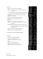
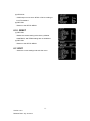
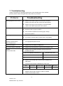
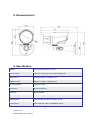
1
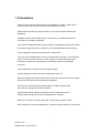
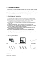
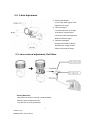
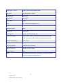
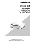
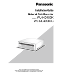
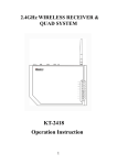
VN310SFHD Full HD IR Outdoor Camera INSTRUCTION MANUAL 1 Version 1.0.0 Release Date: July. 04.2013 Dear Customers! By selecting this product, you have decided to use a professional device that guarantees highest quality and reliability. We would like to thank you very much for your confidence and kindly ask you to read the following instructions carefully before Installation and operation in order to take full advantage of all quality features regarding this product. CAUTION RISK OF ELECTRIC SHOCK DO NOT OPEN CAUTION TO REDUCE THE RISK OF ELECTRIC SHOCK, DO NOT REMOVE THE COVER (OR BACK) NO USER SERVICEABLE PARTS INSIDE. The lighting flash with an TO arrowhead symbol, within an equilateral REFER SERVICING QUALIFIED PERSONNEL. triangle is intended to alert the user to the presence of non-insulated dangerous voltage within the product’s enclosure that may be of sufficient magnitude to constitute a risk of electric shock to persons. The exclamation point within an equilateral triangle is intended to alert the user to the presence of important operating and maintenance (servicing) instructions in the literature accompanying the appliance. INFORMATION - This equipment has been tested and found to comply with limits for a Class A digital device, pursuant to part 15 of the FCC Rules. These limits are designed to provide reasonable protection against harmful interference when the equipment is operated in a commercial environment. This equipment generates, uses, and can radiate radio frequency energy and, if not installed and used in accordance with the instruction manual, may cause harmful interference to radio communications. Operation of this equipment in a residential area is likely to cause harmful interference in which case the user will be required to correct the interference at its own expense. WARNING – Changes or modifications not expressly approved by the manufacturer could void the user’s authority to operate the equipment. CAUTION – To prevent electric shock and risk of the fire hazards: Do NOT use power source other than that specified. Do NOT expose this appliance to rain or moisture. This installation should be made by a qualified service person and should conform to all local codes. 2 Version 1.0.0 Release Date: July. 04.2013 Table of contents 1. Precautions ------------------------------------------------------------------------------------------------------ 4 2. Limitation of liability ------------------------------------------------------------------------------------------ 5 3. Disclaimer of warranty --------------------------------------------------------------------------------------- 5 4. Package ----------------------------------------------------------------------------------------------------------- 5 5. Installation -------------------------------------------------------------------------------------------------- 6 ~ 8 5-1. How to mount to ceiling/wall 5-2. 3-Axis Adjustment 5-3. Lens external adjustment, Ext-Video 5-4. Application of HD-SDI output 6. Function and operation ------------------------------------------------------------------------------- 9 ~ 18 6-1. On Screen Display(OSD) 6-2. Setting up the menu 6-3. LENS 6-4. EXPOSURE 6-5. WHITE BAL 6-6. DAY&NIGHT 6-7. NR(Noise Reduction) 6-8. SPECIAL 6-9. ADJUST 6-10. RESET 6-11. EXIT 7. Trouble shooting guide ------------------------------------------------------------------------------------ 19 8. Dimension ------------------------------------------------------------------------------------------------------ 20 9. Specification ------------------------------------------------------------------------------------------ 20 ~ 21 3 Version 1.0.0 Release Date: July. 04.2013 1. Precautions · Please read the manual carefully before the installation in order to make use the camera to be set up correctly and to have the best picture quality. · Please keep the manual in good condition for your future reference and service application. · Installation and services should only be carried out by an authorized personnel according to local safety regulations. · If any liquid or solid matter gets into the housing, immediately disconnect the camera from power supply and have it checked by your authorized dealer before reusing. · Avoid installing the camera at extremely hot or cold places. · If you are not a certified person, never try to dismantle the camera. To avoid electric shock, never remove the screws or covers. There are no parts inside that need maintenance by the user. All maintenance should be carried out by qualified personnel. · Avoid installing the camera at a place of high humidity. · Avoid installing the camera at the place exposed to gas or oil. · Keep the top glass of the lens always clean in order to obtain the best picture quality all the time. Be careful not to be stained by fingerprint. · Don't face the camera directly toward sunlight or sunlight reflecting area. The sensor may go defective at this condition. · Please give a special attention to keep the unit from dangerous drop or external shock during the process of transportation or handling. · Never try to touch the camera in wet hand. It may cause an electric shock. · Do not expose the camera to radioactivity. It causes a serious damage on the sensor. 4 Version 1.0.0 Release Date: July. 04.2013 2. Limitation of liability This publication is provided “AS IS” without warranty of any kind, either express or implied, including but not limited to, the implied warranties of merchantability, fitness for any particular purpose, or non-infringement of the third party's right. This publication could include technical inaccuracies or typographical errors. Changes are added to the information herein, at any time, for the improvements of this publication and/or the corresponding product(s). 3. Disclaimer of warranty In no event shall seller be liable to any party or any person, except for replacement or reasonable maintenance of the product, for the cases, including but not limited to below : (1) Any damage and loss, including without limitation, direct or indirect, special, consequential or exemplary, arising out of or relating to the product; (2) Personal injury or any damage caused by inappropriate use or negligent operation of the user; (3) Unauthorized disassemble, repair or modification of the product by the user; (4) Inconvenience or any loss arising when images are not displayed, due to any reason or cause including any failure or problem of the product; (5) Any problem, consequential inconvenience, or loss or damage, arising out of the system combined by the devices of third party. (6) Any claim or action for damages, brought by any person or organization being photogenic subject, due to violation of privacy with the result of that surveillancecamera's picture, including saved data, for some reason, becomes public or is used for the purpose other than surveillance. 4. Package contents Full HD IR Outdoor Camera 1EA Tapping screw 3EA Instruction Manual 1EA Plastic anchor 3EA 5 Version 1.0.0 Release Date: July. 04.2013 L-Wrench 1EA Extra Video cable 1EA 5. Installation 5-1. How to mount to ceiling/wall (Ceiling) (Wall) ① Drill three screw holes on the wall plate to fix three plastic anchors (supplied) in the holes. ② Fix the plastic anchors in the holes. ③ Position the mounting bracket on the screw points. ④ Fix the mounting bracket by tightening the screws. ⑤ Slightly loosen bolt (A) then adjust tilt(180˚) and rotation(360˚) of the camera using a serration on the bracket and tighten the bolt firmly. ⑥ Slightly loosen bolt (B) then adjust pan(360˚) of the camera and tighten the bolt firmly. 6 Version 1.0.0 Release Date: July. 04.2013 5-2. 3-Axis Adjustment ① Panning 360 degree Turn the pan base right or left to adjust the pan angle. ② Tilting 90 degree Loosen the tilt lever on the right or left side of camera board. Control the camera tilt angle and fasten the tilt lever again. ③ Rotation 180 degree Grasp the front side of camera board and turn it right or left to set the exact angle of image. 5-3. Lens external adjustment, Ext-Video - Focus (Near-Far) Unlock the focus lever by turning counterclockwise. Move the lever to adjust the focus. Lock the lever by turning clockwise. 7 Version 1.0.0 Release Date: July. 04.2013 - Zoom (Tele-Wide) Unlock the zoom lever by turning counterclockwise. Move the lever to adjust the zoom. Lock the lever by turning clockwise. - How to use EXT-video Connect Extra video output connector (A) to camera tester or local monitor as shown in the above. 5-4. Application of HD-SDI output Impedance alliance in the system connection. Make sure to connect the cable with the power off. Please locate the impedance switches of each equipment as instructed. Locate the switch to Hi-z position for the interim equipments. Locate the switch to 75Ω for the last equipment. 8 Version 1.0.0 Release Date: July. 04.2013 6. Function and operation 6-1. On Screen Display SETUP LENS DC MANUAL EXPOSURE SHUTTER AGC SENS-UP ACCE DEFOG BACKLIGHT WHITE BAL ATW AWC→SET DAY&NIGHT AUTO NR SPECIAL ADJUST BRIGHTNESS RETURN INDOOR OUTDOOR MANUAL COLOR B/W EXT 2DNR 3DNR LEVEL SMART NR RETURN CAM TITLE D-EFFECT MOTION PRIVACY RETURN LANGUAGE DEFECT RS485 VERSION SHARPNESS MOTION OSD LSC RETURN NTSC/PAL RESET FACTORY RETURN EXIT 9 Version 1.0.0 Release Date: July. 04.2013 6-2. Setting up the menu Settings can be made using the OSD Switch located on the back of the camera. 1. Press the button to access the SETUP mode. The SETUP menu is displayed on the monitor. 2. Please select any function you wish to activate by using the UP/DOWN selections. The cursor can be moved up or down by using the UP/DOWN selections. Position the cursor to point to the function you wish to operate. * MAIN-menu : Use UP/ DOWN selections. / SUB-menu : Use LEFT/ RIGHT selection 3. Change the status of the selected feature using the LEFT/RIGHT selections. When the LEFT or RIGHT selection is done, available values and modes are displayed in order. Please keep the selection until you get to the mode you wish to operate. 4. When completed, move the cursor indicator to ‘EXIT’ position and press the Button to finish the setting. ☞ NOTE If Appears at the mode you wish to operate, it means that there is a sub-menu which can be selected by OSD Switch. 10 Version 1.0.0 Release Date: July. 04.2013 6-3. LENS (1) DC - When DC lens is used. (2) MANUAL(※ Default) - When MANUAL lens is used. 6-4. EXPOSURE (1) SHUTTER A. AUTO: The shutter speed is controlled automatically. B. FLK: Please select FLK mode when flickering occurs on the screen, due to an imbalance between illumination and frequency. C. FIXED : The shutter speed is controlled manually. - You can select the speed from ‘1/30’ to ‘1/50,000 sec. (NTSC), ‘1/25’ to ‘1/50,000 sec. (PAL). - You can select Digital Slow Shutter between x2 ~ x30. (DSS) (2) AGC - LOW: Allows automatic gain control from 0 to 20dB. - MIDDLE: Allows automatic gain control from 0 to 30dB. - HIGH: Allows automatic gain control from 0 to 42dB.(※ Default) (3) SENS-UP - Low light sensitivity is greatly improved with the use of this function. - Low light sensitivity level is adjustable from 2 to 30 times. - When SENS-UP level is higher, the picture becomes brighter while noise is increased at the same rate of SENS-UP. ON : Adjustable SENS-UP level between x2 ~ x30. OFF: SENS-UP is disabled. ※ Default setting is <x8> 11 Version 1.0.0 Release Date: July. 04.2013 (4) BRIGHTNESS - Adjusts the brightness in 1 ~ 100(Default 50) (5) ACCE(Adaptive Contrast & Color Enhancement) - D-WDR Function scans both dark and bright clearly and this model realized its best set up for the most of different levels of backlit or contrast lighting situations. (6) DEFOG - Images in extraordinary environment such as fog or rain or in a very strong luminous intensity have DR (dynamic range), lower than ordinary images. Contrast-based defog function, which is used to overcome such shortcoming. 12 Version 1.0.0 Release Date: July. 04.2013 (7) BACKLIGHT - BLC Used for backlight environment.(LOW/MIDDLE/HIGH) - HSBLC Can mask the head lights to view car license number plate more clearly. (8) RETURN - Returns to the SET MENU. 6-5. WHITE BAL This is useful when the cameras are installed in different artificial lighting conditions where a standard ‘White Balance’ condition is not suitable for all. - ATW(Auto Tracking White Balance) This mode can be used within the color temperature range 2,000° ~ 20,000°K. - AWC→SET Please press the Tact SW while the camera is directed at a piece of white paper to obtain the optimum state under current illumination. If the environment including the light source is changed, you have to adjust the white balance again. - INDOOR This is mode can be used within the color temperature range of 2,500° ~ 7,000°K. - OUTDOOR This is mode can be used within the color temperature range of 1,800° ~ 10,500°K. - MANUAL In the manual mode, the user can choose the color and temperature. The user can adjust the color and temperature by controlling red and blue gain 13 Version 1.0.0 Release Date: July. 04.2013 6-6. DAY&NIGHT You can display pictures in Color or B/W. - AUTO : Automatically turns between Day and Night Mode according to AGC operation. ● DELAY : You can select the duration time about changing the Day/Night mode 0 ~ 60. ● D→N : To adjust lux level for switching Day to Night. ● N→D : To adjust lux level for switching Night to Day. ● RETURN : Returns to the SET MENU. ☞ NOTE D/N set up is excluded in the D/N camera with photo cell(CDS Sensor) - Color : The picture is always in color. - B/W : The picture is always in black and white. ● BURST : Burst signal can be turned on/off. ● IR SMART : Intelligent IR response against IR saturation. ● IR LED : ● IR PWM : Control the PWM duty. ● RETURN : Returns to the SETUP MENU. 6-7. NR(Noise Reduction) Noise Reduction (NR) is used in order to obtain a high quality output image and enhance compression efficiency. Offers Edge Preserving 2D NR and Motion Adaptive 3D NR. (1) 2DNR - Cuts off the noise in low light condition. (2) 3DNR - Cuts off the noise in low light condition. ● S-LEVEL : Adjust the 3DNR start level. ● E-LEVEL : Adjust the 3DNR END level. ● RETURN : Returns to the 2D&3D NR MENU. (3) LEVEL : - Adjust the noise reduction level. (4) SMART NR - If there is movement at the low light condition, the 3DNR level will be decreased, On the contrary, if there is no movement, the 3DNR level will be increased. (5) RETURN - Returns to the SET MENU. 14 Version 1.0.0 Release Date: July. 04.2013 6-8. SPECIAL (1) CAM TITLE If you enter a title, the title will appear on the monitor. 1. Please position the arrow to point to ‘SPECIAL’ on the moving UP or DOWN direction. 2. Then, select ‘ON’ by using the LEFT and RIGHT selection. When you press the button to complete ‘ON’, then ‘CAM TITLE’ will be displayed. ☞ NOTE · If ‘OFF’ is selected, the CAM TITLE does not appear on the monitor even if it has been input. 3. Up to 15 letters are available for the CAM TITLE. ① Please move the cursor to the letter to choose by using the UP and DOWN selections. ② Set an ID from 0,1,~8,9, A,B, ~Y,Z by using the UP, DOWN, LEFT and RIGHT selections. ③ Lock in the letters by using the button. When the letter is locked in, the cursor moves to the next space. ④ Please repeat the above to input CAM TITLE. 4. When a name has been chosen, please select a position for the name to display. ① Please move the cursor onto ’POS’ and then press the button. ② The name will appear at the top right corner. ③ Please find the position you wish to display the name by using the 4 directional selections, and then press the button to finish. 5. Please select ‘END’ and then press the button to complete CAM TITLE input. (2) D-EFFECT (Defect Compensation) - FREEZE : You can view still or moving pictures. - MIRROR : MIRROR/V-FLIP/ROATE - D-ZOOM ● PIP : ON/OFF ● D-ZOOM : Adjust the x2.0 ~ x64. ● PAN&TILT : Adjust the PAN&TILT ● DEFAULT : Initialize all setting of the D-ZOOM. ● RETURN : Returns to the D-EFFECT MENU. - NEG. IMAGE : Negative ON/OFF - RETURN : Returns to the SPECIAL MENU. 15 Version 1.0.0 Release Date: July. 04.2013 (3) MOTION - SELECT : You can select up to 3 MD areas. - DISPLAY : Determines whether to use the MD area selected in AREA SELECT. ● ON : Determines the coordinate of the vertical/horizontal position. Determines the coordinate of the vertical/horizontal size. - SENSITIVITY : Determines the coordinate of the sensitivity. - MOTION VIEW : ON/OFF. - DEFAULT : Initialize all setting of the MOTION. - RETURN : Returns to the SPECIAL MENU. (4) PRIVACY - SELECT : You can select up to 8 PRIVACY areas. - DISPLAY : Determines whether to use the MD area selected in AREA SELECT. - COLOR : Black, Gray1,Gray2, White, Orange, Yellow, Cyan1 Cyan2, Green1, Green2, Green3, Magenta1, Magenta2 Red, Blue1, Blue2 - DEFAULT : Initialize all setting of the PRIVACY. - RETURN : Returns to the SPECIAL MENU. (5) LANGUAGE : ENGLISH/JAPANESE/CHINESE (6) DEFECT - LIVE DPC : Live Dead Pixel Correction - LEVEL : Adjust the LEVEL 00 ~ 60 - STATIC DPC : Static Dead Pixel Correction - START - LEVEL : Adjust the LEVEL 00 ~ 60 - SENS-UP : Adjust the LEVEL x2 ~ 60 - RETURN : Returns to the SPECIAL MENU. 16 Version 1.0.0 Release Date: July. 04.2013 (7) RS485 - CAM ID : Determines the camera ID number in 001 ~ 255 - ID DISPLAY : Defines the location where camera ID is displayed on the screen. 4 location of top, bottom, left and right can be selected. - BAUDRATE : Selects baud rate for RS485 communication among (Default:9600)2400/4800/9600/19200/38400. (8) VERSION - Shows firmware version of this camera unit. (9) RETURN - Returns to the SETUP MENU. 6-9. ADJUST (1) SHARPNESS - SHARPNESS : ON/OFF - LEVEL : Adjust the LEVEL 0 ~ 100 - RESOLUTION : ON/OFF - RETURN : Returns to the ADJUST MENU. (2) MONITOR A. LCD - GAMMA : Adjust the LEVEL USER ~ 1.00 - BLUE GAIN : Adjust the LEVEL 0 ~ 100 - RED GAIN : Adjust the LEVEL 0 ~ 100 - RETURN : Returns to the ADJUST MENU. B. CRT - BLACK LEVEL : Adjust the LEVEL -30 ~ 30 - BLUE GAIN : Adjust the LEVEL 0 ~ 100 - RED GAIN : Adjust the LEVEL 0 ~ 100 - RETURN : Returns to the ADJUST MENU. (3) OSD - TEXT COLOR : WHITE, BLACK, YELLOW, CYAN, GREEN, Magenta, RED, BLUE - OUTLINE : ON/OFF - RETURN : Returns to the ADJUST MENU. (4) LSC - Lens Shading Correction (LSC) corrects the phenomenon where the image gets darkened or blurred on the periphery. 17 Version 1.0.0 Release Date: July. 04.2013 (5) NTSC/PAL - CVBS output can be set to NTSC or PAL according to local TV standard. (6) RETURN - Returns to the SETUP MENU. 6-10. RESET (1) RETURN - Resets the camera setting to the factory defaults. CAMERA ID, 485 TERM settings are not initialized.. (2) RETURN - Returns to the SETUP MENU. 6-11.EXIT - Saves the current settings and exits the menu. 18 Version 1.0.0 Release Date: July. 04.2013 7. Troubleshooting If there are problems in operating, please refer to the checklist below. If the problem persists, please contact the agent where this product is purchased. Problems Nothing appears on the screen. Troubleshooting Please check that the power cord and line connection between the camera and the monitor are fixed properly. Please check that you have properly connected VIDEO cable to the VIDEO output jack of the camera. The image on the screen is dim. Is lens stained with dirt? Clean your lens with soft, clean cloth. Set the monitor to proper condition. If the camera is exposed to too strong light, change the camera position. The image on the screen is dark. The camera is not working Adjust the contrast feature of the monitor. If you have an interim device, set the 75Ω / Hi-z properly. Please check that you have properly connected the camera properly, and the surface to an appropriate power source. of the camera is hot. Color is not correct. Please check the setting of AWB menu . The screen flickers continually. Please check that direction of camera turns toward the Sun. RS-485 Please check the polarity between RS-485 Control Port communication fails. and RS-485 cable. 485 Control Board Connection Port RS-485 Control Port (+)CONNECTION TERMINAL(TRX+) 485+ (-)CONNECTION TERMINAL(TRX-) 485- Please check the RS-485 Communication establishment initial value. *RS-485 Communication establishment initial value Item Camera ID BAUD RATE Initial value 001 9600 UART MODE RET PKT 8-NONE-1 ENABLE We recommend that you make ground connect between camera and controller in order to maintain safety communication control. 19 Version 1.0.0 Release Date: July. 04.2013 8. Dimension(mm) 9. Specification MODEL Full HD CCTV IR Outdoor Camera Sensor Device SONY 1/2.9" progressive scan CMOS, 2MegaPixel Total Pixels 2010(H) X 1241(V) = 2.48 Mega pixel Effective Pixels 1984(H) x 1105(V) = 2.19 Mega pixel Scanning System Progressive Scan Horizontal More than 1000 TVL S/N Ratio More than 52dB Min. Illumination 0 Lux Shutter Speed 1/30s Default,(Long Exposure Mode, ~1Sec) Video Output 1920 x 1080 30P, 1280 x 720 60P(Mode Select) 20 Version 1.0.0 Release Date: July. 04.2013 Video Output Format 1.485G/s, HD-SDI Output (SMPTE 292M) AV Output 1V p-p Composite. 75 Ohms Digital Output SDI Output Day & Night D/N Output Serial Port RS485 Lens 3.5 ~ 16mm Varifocal Megapixel Lens Iris Control AUTO Viewable Distance 20M MTBF of IR 20,000 hours Power Source DC 12V, DC12V/AC24V(Optional) Power Consumption IR OFF : 220mA / DC12V(2.7W), 280mA/DC12V(3.5W)/140mA/AC24V(3.5W) IR ON : 460mA / DC12V(5.6W), 650mA/DC12V(8.0W)/290mA/AC24V(7.0W) Operating Temperature -10°C ~ 50°C Storage Temperature -20°C ~ 70°C Operating Humidity Under 90% Non-condensing Measurement (mm) 80.5(W) x 148.4(H) x 206(D) Weight ( Approx.) 800 g OSD LENS/ EXPOSURE/ WHITE BAL / DAY&NIGHT / NR/ MOTION/ DEFOG ACCE/ LSC/ PRIVACY/ BRIGHTNESS, etc. 21 Version 1.0.0 Release Date: July. 04.2013