1
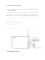
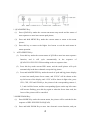
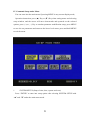
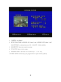
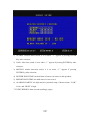
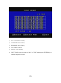
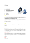
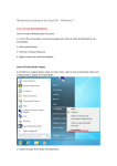
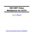
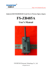
2.4GHz WIRELESS RECEIVER & QUAD SYSTEM KT-2418 Operation Instruction 1 I. Summary Respectable users: we appreciate that you have chose the color 4-channel multiplexer of our company, this manual will introduce the functional features, installation and operation method of the product to you, so that you will get acquainted with our product as soon as possible. Notes: the information in the manual is the information when the manual is published, the manufacturer will reserve the rights to modify and improve the product, and any modifications to the parameters will be made without any notification. It is prohibited to use the product under the environment of high temperature and high moisture, especially in shower room under high temperature; Don’t put the product at the places under direct sunshine (such as vehicles which are parked on open areas and sand beach); Don’t wash and wipe the product with diluent or other chemical detergent; Only the specified AC adapter and power source can be used; don’t use other power sources, to avoid causing serious damage to the product; Please cut off the power source when the product is not used; Don’t disassemble the product without permission, please contact the distributor or our company in case of any doubts. 2. Key Functional Features Time and date display and location setup Camera name setup Auto sequence Camera picture quality setup Monitoring 4x electronic zoom function Connect PC, a single synchronous recording or four camera signals 2 II. Instruction for Wire Connection Insert the yellow video cable and red audio cable into the VIDEO and AUDIO IN of TV set or monitor. And the picture you receive will display on the TV set or monitor. Select AUDIO CH, and you will receive the voice from your wireless camera synchronistically. connects to the USB line can be displayed on a computer on-site audio-video receiver, and synchronization of audio and video recording scene III. Instruction for Keys and Operation Schematic Drawing for Panel: Schematic Drawing on the Back: 3 1. QUAD/MENU Key: (1) Press QUAD Key under the current non-menu setup mode and the status of auto sequence to enter into current quad picture; (2) Press and hold MENU Key under the current status to return to the menu picture; (3) Press this key to return to the higher level menu or exit the main menu in menu operation. 2. AUTO/FREEZE Key: (1) Press this key under the current status of QUAD to enter into auto sequence function, and it will cycle automatically in the sequence of QUAD-CH1-CH2-CH3-CH4 according to the set sequence time. (2) Press this key under current PIP1 status, and the small picture will cycle automatically in the three channels except the big picture. (3) Press and hold FREEZE Key under the mode of quad and big picture display to enter into small picture freeze status, and “F1234” will be shown on the top left corner of the display, and “1234” will be shown in light color; press CH1, CH2, CH3 and CH4 Keys, the picture of the corresponding camera 1, 2, 3 and 4 will be frozen, and the corresponding figures on the top left corner will become flashing, press this key again or when the freeze time ends, the freeze of the picture will be cancelled. 3. MODE/ZOOM Key: (1) Press MODE Key under the current status, the picture will be switched in the sequence of PIP1-PIP2-PIP3-POP-QUAD; (2) Press and hold ZOOM Key to enter into electronic zoom function, and you 4 may adjust the scope of zoom through “▲”, “▼”, “ +” and “—” keys; press AUTO Key after selecting the scope, and the selected scope will be zoomed to quadruple the original; (3) Press and hold CH1, CH2, CH3 and CH4 after entering into ZOOM function to zoom the corresponding quad picture to quadruple the original; (4) Press ENTER Key After zoom to exit the zoom status, and return to the zoom zone selection status; (5) Press ZOOM or QUAD to return to the original status. 4. “ENTER” Key: under the menu status, this key functions as carriage return; press this key after selecting menu to enter into the selected submenu. 5. “1”, “2”, “3”, “4”/“▲”, “▼”, “+” , “—” Keys (1) These four keys may be used to display or freeze the picture of the corresponding camera in the current quad picture display; (2) Under the menu selection mode, these four keys may be used to move the position of the cursor upwards and downwards and change the value of the corresponding cursor. 5 IV. Command Setup under Menu You can enter into the main menu if pressing MENU in any current display mode; Operation instruction: press (▲) Key or (▼) Key when setting menu and selecting setup window, and the cursor will move downwards and upwards on the selected options, press (+) or (—) Key to conduct parameter modification setup; press MENU to save the set parameters and return to the lower level menu; press and hold MENU to exit the menu. 1. SYSTEM SETUP (Setup of time, date, system and reset) Press “ENTER” to enter into setup option after selecting SYSTEM SETUP with “▲” and “▼” under the main menu mode. 6 (1) DATE: system date, YY-MM-DD (year, month and date) arrangement; press “▲” and “▼” keys for a selection at first and then press “—” and “+” keys to modify the sequence of the arrangement (MM-DD-YY); press “▲” and “▼” keys to select the date and then press “—” and “+” keys to modify/set the date; (2) TIME: system time, HH:MM:SS (hour, minute and second) setup; press “▲” and “▼” keys for a selection at first and then press “—” and “+” keys to modify the sequence of the arrangement (MM-SS-HH); press “▲” and “▼” keys to select the clock and then press “—” and “+” keys to modify/set the time; (3) SYSTEM FORMAT: color system setup, use control key to select the two systems of “PAL” or “NTSC”; (4) SYSTEM ID NUMBER: system ID number setup (unavailable in this product); (5) KEY LOCK: key lock, when “ON” is selected, the keys other than MENU/QUAD Key are unavailable under current mode; when “OFF” is selected, the key function will be recovered and available under current mode; 7 (6) FACTORY RESET: system reset, when “YES” is selected, press “ENTER” to recover the system to factory setup status; “NO” means unrecoverable. 2. DISPLAY SETUP: display setup 1)DISPLAY ON SCREEN: display on screen (1) TITLE: camera title switch, “∨” is on; (2) DATE: date display switch, “∨” is on; (3) TIME: time display switch, “∨” is on; 2) SCREEN POSITION: screen row/field display (1) X: row center display; (2) Y: field center display. 3) BORDER COLOR: border parting line color (1) BLACK: black; (2) GRAY1: grey; (3) GRAY2: off white; (4) WHITE: white; 8 (5)OFF: off, when “OFF” is selected, the scene will not be divided by border line. 3. AUTO SEQUENCE: auto switch setup 1) QUAD: means the picture sequence time setup mode of QUAD and CH1-CH4; 2) CAMERA1: set the time for image to stay in CH1; 3) CAMERA2: set the time for image to stay in CH2; 4) CAMERA3: set the time for image to stay in CH3; 5) CAMERA4: set the time for image to stay in CH4. 4. CAMERA SETUP: camera setup 9 1) CAMERA: the channel needed to be set; 2) TITLE: title setup mode, when this option is selected, figures and letters on the top of screen can be edited; 3) BRIGHTNESS: brightness adjust 4) CONTRAST: contrast control 5) SATURATION: hue control; 6) HUE: saturation control; 7) SHARPNESS: sharpness control 8) MIRRORING: image mirroring switch. 5. MOTION SETUP: motion alarm setup 10 1) CAMERA: set channel 2) DETECTION TIME: ALWAYS ON: alarm is on, ALWAYS OFF: alarm is off; ON/OFF TIME: set alarm time (now ON: 11:00 OFF: 12:00 available); 3) SENSITIVITY: detection sensitivity setup; 4) VELOCITY: alarm velocity setup; 5) MASKING AREA: detected area coordinate (X .Y: 00.00); 6. EVENT SETUP: alarm setup (it is proposed not to open it in this product) 11 1) ALARM: external alarm switch, it is on when “∨” appears if pressing ENTER Key after selection; 2) LOSS: video loss switch, it is on when “∨” appears if pressing ENTER Key after selection; 3) MOTION: motion detection switch, it is on when “∨” appears if pressing ENTER Key after selection; 4) BUZZER HOLD TIME: the hold time of buzzer (no buzzer in this product); 5) REPORT HOLD TIME: the hold time of event record; 6) ALARM POLARITY: the high and low potential setup of buzzer alarm, “LOW” is low, and “HIGH” is high. 7. EVENT REPORT: alarm records (totaling 6 pages) 12 1) NO: serial number of alarm; 2) YY-MM-DD: date of alarm; 3) HH:MM:SS: time of alarm; 4) CH: channel of alarm 5) EVENT: event of alarm; 6) LIST CLEAR: to clear records, set “NO” as “YES” and then press ENTER Key to confirm completion of clear. 13 V. Technical Parameters: System PAL NTSC CH1:2.414GHz CH2:2.432GHz, Receiving Frequency CH3:2.450GHz CH4:2.468GHz Source Voltage 12V 1.2A Current Consumption 750mA Receiving Sensitivity -88dBm Antenna Input Impedance 75 ohm Video Output Level 1Vp-p Audio Output Level 1Vp-p Image Resolution 720×576(PAL)720×480(NTSC) Image Refresh Rate 60Hz/second(NTSC)50Hz/second(PAL) Single picture, two picture, PIP, POP or four picture can be Video Output Type displayed and automatically Ambient Temperature Interface type Coding manner -30°C-60°C USB 2.0 MPEG Software attached Application attached Support operation systems win98/ME/2000/XP Highest image resolution 1440*1152 VI. Requirements of system 14 switched CPU:1.8GHZ or up RAM:256M or up Hard disk:10GB Operation system:win2000,winXP USB 2.0 port VII. Install driver: Connect this unit to a computer and install USB2.0 driver 1.Find the file STK1160 Driver in the disk, open it, click“Setup start driving installation . 2.If this product is connected to your computer, disconnect it. Click“OK” to continue. 3.Click“Install”. 15 4.Click“Continue Anyway” to next. 5. Click “Finish” to end the installation to driver 6.After clicking“Finish”, there is a picture diction, click“OK”, and connect the product to your computer to continue installing, 16 7.After connected, there is a dialogue, select“NO, not this time”, click“NEXT”. 8. Click“NEXT”. 9.Click“Continue Anyway” go to the next step 10.Click“Finish”. There is a reminder,“hardware has been installed and can be used”. Then go to monitor. 17 VIII. Installation of software: 1.Click the file“setup.exe”, click the following icon 2.Select relative language and click“OK”. 3.Click “NEXT” to continue. 4.Select relative destination location. Click “Next” to continue. 18 5.Click “Next”. 6.Click “Install”. 7.Click “Finish”. At this time, your software “Wireless Camera Watcher” has been successfully installed. 19 X. Directions on operation of Wireless Camera Watcher: For initial installation and operation, you should click high-level settings at first and then click Image tab to select system (PAL/BDGHI NTSC/M) and input manner. If you are using wireless camera or A/V IN, you should select “Group” . Introduction of functions of buttons 20 A. Show Time - Display date & time in red within capture screen. B. Timer Shot - Captures and saves a bitmap picture after five seconds. Timer adjustable by clicking on have file options button. Ref. D) C. Snap Shot -Capture and saves an instant bitmap picture. D. Save File - Displays and allows capture of destination path and filename of bitmap capture file. E. Motion Detection - launched motion and set up monitoring. Apply to 320x240 resolution. F. Record - Capture Video Recording G. Advanced Setting: Set up the video parameters, adjust the brightness , contrast and color. Etc. H. Recorder Settings - Adjust video and audio recorder settings I. Video and Image capture size. J. Viewer Window Still Shot Capture 1. Select picture capture size format (ref. H in Figure1) 2. Enter destination filename and path (ref. D in Figure1) 3. Focus camera on source. 4. Click on Snap Shot Button (ref. C in Figure1) (Note. Still Shots can be captured using the silver button on the spotter webcam) Video Capturing 1. Focus camera on capture source. 2. Click on the run Recorder button to begin recording. (ref. in Figure1). 3. To stop recording click on the same button. 4. Output file path [*] and audio settings can be changed by clicking the Record Settings button ( ref. J in Figure1) (Note. Audio settings only apply to the Scout Camera that has audio capture features) [*] Default files will be saved under Wireless Camera Watcher installing folder Such as: C:\Program Files\Wireless Camera Watcher Resolution Settings You can select the video capture size by simply selecting 1 of the 5 video resolution options available (denoted by H in Figure1). The default setting resolution is 320X240. You will immediately see the results in the viewer screen alongside the control centre panel. Motion Detection You can select the Motion Detection function by simply selecting Scan object, Capture still, Open alarm while detects motion. (denoted by F in Figure1). IX. Specifications of receiver: 21 Note: [1] The Motion Detection function, only for 320x240 . [2] Default files will be saved under Wireless Camera Watcher installing folder such as: C:\Program Files\Wireless Camera Watcher . Advanced Settings The advanced settings window allows the user to adjust image characteristics by clicking on the Camera Controls tab or adding special effects by clicking on the advanced settings tab. Camera Controls Tab Use the picture property window shown below to adjust picture quality. By sliding the Control Adjust Bar the effect can be seen immediately on the viewer window. These setting can be saved by clicking the save button or cancelled by restoring the default settings. Check Box control features include:- Vertical Flip, Mirror Flip and Backlight Composition. 22 IIX.Spare Parts 1. Wireless Receiving 4-Channel Multiplexer 1 PCS 2. Power adapter 1 PCS 3. A/V output line 1 line 4. English Operation Instruction 1PCS 5. Remote controller 1PCS 6. 2.4G antenna 1PCS 7. Driver, CD of software recorded 1PCS 8. USB cable 1 PCS 23