1
Network Camera
RHP International - www.Rock2000.com
Toll Free: 1-888-919-2263
Outside the U.S.: ++1-845-343-4077
Fax: +1-845-343-4299
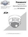
Operating Instructions
Model No.
WV-NW484S
Before attempting to connect or operate this product,
please read these instructions carefully and save this manual for future use.
WARNING:
• This apparatus must be earthed.
• All work related to the installation of this product
should be made by qualified service personnel
or system installers.
• The connections should comply with local
electrical code.
CAUTION
RISK OF ELECTRIC
SHOCK
DO NOT OPEN
CAUTION: TO REDUCE THE RISK OF ELECTRIC SHOCK,
DO NOT REMOVE COVER (OR BACK).
NO USER-SERVICEABLE PARTS INSIDE.
REFER SERVICING TO QUALIFIED SERVICE PERSONNEL.
SA 1965
SA 1966
2
The lightning flash with
arrowhead symbol, within an
equilateral triangle, is intended
to alert the user to the presence
of uninsulated "dangerous
voltage" within the product's
enclosure that may be of
sufficient magnitude to
constitute a risk of electric
shock to persons.
The exclamation point within an
equilateral triangle is intended
to alert the user to the presence
of important operating and
maintenance (servicing)
instructions in the literature
accompanying the appliance.
For Canada
This Class A digital apparatus complies with
Canadian ICES-003.
For U.S.A
NOTE: This equipment has been tested and
found to comply with the limits for a Class A
digital device, pursuant to Part 15 of the FCC
Rules.
These limits are designed to provide
reasonable protection against harmful
interference when the equipment is operated in
a commercial environment. This equipment
generates, uses, and can radiate radio
frequency energy and, if not installed and used
in accordance with the instruction manual, may
cause harmful interference to radio
communications.
Operation of this equipment in a residential
area is likely to cause harmful interference in
which case the user will be required to correct
the interference at his own expense. FCC
Caution: To assure continued compliance,
(example - use only shielded interface cables
when connecting to computer or peripheral
devices). Any changes or modifications not
expressly approved by the party responsible for
compliance could void the user's authority to
operate this equipment.
The serial number of this product may be found
on the surface of the unit.
You should note the serial number of this unit
in the space provided and retain this book as a
permanent record of your purchase to aid
identification in the event of theft.
Model No.
Serial No.
Important Safety Instructions
1) Read these instructions.
2) Keep these instructions.
3) Heed all warnings.
4) Follow all instructions.
5) Clean only with dry cloth.
6) Do not block any ventilation openings. Install in accordance with the manufacturer's instructions.
7) Do not install near any heat sources such as radiators, heat registers, stoves, or other
apparatus (including amplifiers) that produce heat.
8) Do not defeat the safety purpose of the polarized or grounding-type plug. A polarized plug
has two blades with one wider than the other. A grounding type plug has two blades and a
third grounding prong. The wide blade or the third prong are provided for your safety. If the
provided plug does not fit into your outlet, consult an electrician for replacement of the
obsolete outlet.
9) Protect the power cord from being walked on or pinched particularly at plugs, convenience
receptacles, and the point where they exit from the apparatus.
10) Only use attachments/accessories specified by the manufacturer.
11) Use only with the cart, stand, tripod, bracket, or table specified by the manufacturer, or sold
with the apparatus.
When a cart is used, use caution when moving the cart/apparatus combination to avoid injury
from tip-over.
S3125A
12) Unplug this apparatus during lightning storms or when unused for long periods of time.
3
Limitation of Liability
THIS PUBLICATION IS PROVIDED "AS IS"
WITHOUT WARRANTY OF ANY KIND,
EITHER EXPRESS OR IMPLIED,
INCLUDING BUT NOT LIMITED TO, THE
IMPLIED WARRANTIES OF MERCHANTABILITY, FITNESS FOR ANY PARTICULAR
PURPOSE, OR NONINFRINGEMENT OF
THE THIRD PARTY’S RIGHT.
THIS PUBLICATION COULD INCLUDE
TECHNICAL INACCURACIES OR
TYPOGRAPHICAL ERRORS. CHANGES
ARE ADDED TO THE INFORMATION
HEREIN, AT ANY TIME, FOR THE
IMPROVEMENTS OF THIS PUBLICATION
AND/OR THE CORRESPONDING
PRODUCT (S).
Disclaimer of Warranty
IN NO EVENT SHALL MATSUSHITA
ELECTRIC INDUSTRIAL CO,.LTD. BE
LIABLE TO ANY PARTY OR ANY PERSON,
EXCEPT FOR REPLACEMENT OR
REASONABLE MAINTENANCE OF THE
PRODUCT, FOR THE CASES, INCLUDING
BUT NOT LIMITED TO BELOW:
(1) ANY DAMAGE AND LOSS, INCLUDING
WITHOUT LIMITATION, DIRECT OR
INDIRECT, SPECIAL, CONSEQUENTIAL
OR EXEMPLARY, ARISING OUT OF OR
RELATING TO THE PRODUCT;
(2) PERSONAL INJURY OR ANY DAMAGE
CAUSED BY INAPPROPRIATE USE OR
NEGLIGENT OPERATION OF THE
USER;
(3) UNAUTHORIZED DISASSEMBLE,
REPAIR OR MODIFICATION OF THE
PRODUCT BY THE USER;
(4) INCONVENIENCE OR ANY LOSS
ARISING WHEN IMAGES ARE NOT
DISPLAYED, DUE TO ANY REASON OR
CAUSE INCLUDING ANY FAILURE OR
PROBLEM OF THE PRODUCT;
4
(5) ANY PROBLEM, CONSEQUENTIAL
INCONVENIENCE, OR LOSS OR
DAMAGE, ARISING OUT OF THE
SYSTEM COMBINED BY THE DEVICES
OF THIRD PARTY;
(6) ANY CLAIM OR ACTION FOR
DAMAGES, BROUGHT BY ANY
PERSON OR ORGANIZATION BEING A
PHOTOGENIC SUBJECT, DUE TO
VIOLATION OF PRIVACY WITH THE
RESULT OF THAT SURVEILLANCECAMERA'S PICTURE, INCLUDING
SAVED DATA, FOR SOME REASON,
BECOMES PUBLIC OR IS USED FOR
THE PURPOSE OTHER THAN
SURVEILLANCE;
(7) LOSS OF REGISTERED DATA CAUSED
BY ANY FAILURE.
Preface
Features
This video surveillance camera is equipped with a 10BASE-T/100BASE-TX terminal
(network terminal) for connection to a network.
This network terminal is used to establish a connection between the camera and a LAN
(Local Area Network) or other network (e.g. Internet) so that images from the camera can
be checked on a personal computer (from here on, "PC") on the network.
..............................................................................................................................
Note
• To check images from the camera on a PC, the PC's network environment must first be
set up. A web browser must also be installed on the PC.
...................................................................................................................................
Super Dynamic III (SUPER-D III)
Auto Back Focus function
VMD (Video Motion Detector) function for detecting motion of an intruder, etc. in the
monitoring area and sounding an alarm by an alarm signal
Progressive output (motion adaptive interlace/progressive conversion function)
Dual Encode Function for simultaneous transmission of JPEG and MPEG-4
Power over Ethernet (IEEE802.3af-compliant, from here on, "PoE") function
SD memory card slot
5
Preface (continued)
About these operating instructions
The Instruction Manual for this camera is comprised of three parts: this book, and the
Operating Manual (PDF) and Setup Manual (PDF).
This book explains how to install the camera, and how to connect and set up the network.
For details on how to operate and set up the camera, refer to the " Operating Manual/Setup
Manual" in the CD-ROM (provided). To read the PDF manual, Adobe Systems Incorporated's Adobe® Reader® is required.
System requirements for a PC
CPU
Memory
Network
Image display
Supported OS
Web Browser
Other
Pentium®4 2.4 GHz or faster
512 MB or more
10BASE-T/100BASE-TX port x 1
Resolution: 1024 x 768 pixels or more
Color scheme: True Color 24 bits or more
Microsoft® Windows® 2000 Professional SP4*
Microsoft® Windows® XP Home Edition SP2
Microsoft® Windows® XP Professional SP2
Microsoft® Internet Explorer® 6.0 SP2
Microsoft® Internet Explorer® 7.0
* When supported OS is Microsoft® Windows® 2000 Professional
SP4, Microsoft® Internet Explorer® 6.0 SP1
CD-ROM drive (for using Operating Instructions and software)
DirectX® 9.0c or later
Adobe® Reader® (for reading Operating Instructions in CD-ROM)
..............................................................................................................................
Note
• When the PC is used in an environment other than that recommended, the image
refresh rate may slow down, operations in the web browser may no longer be possible,
or other problems may occur.
...................................................................................................................................
6
Trademarks and Registered Trademarks
• Microsoft, Windows, ActiveX and DirectX are either registered trademarks or trademarks
of Microsoft Corporation in the United States and/or other countries.
• Intel and Pentium are either registered trademarks or trademarks of Intel Corporation in
the United States and/or other countries.
• Adobe and Reader are either registered trademarks or trademarks of Adobe Systems
Incorporated in the United States and/or other countries.
• The SD logo is a trademark.
• Other names of companies and products contained in these operating instructions may
be trademarks or registered trademarks of their respective owners.
Network Security
As you will use this product connected to a network, your attention is called to the following
security risks.
(1) Leakage or theft of information through this product
(2) Use of this product for illegal operations by persons with malicious intent
(3) Interference with or stoppage of this product by persons with malicious intent
It is your responsibility to take precautions such as those described below to protect yourself
against the above network security risks.
• Use this product in a network secured by a firewall, etc.
• If this product is connected to a network that includes PCs, make sure that the system is
not infected by computer viruses or other malicious entities (using a regularly updated
anti-virus program, anti-spyware program, etc.).
• Protect your network against unauthorized access by restricting users to those who log
in with an authorized user name and password.
• Apply measures such as user authentication to protect your network against leakage or
theft of information, including image data, authentication information (user names and
passwords), alarm mail information, FTP server information and DDNS server information.
• Do not install the camera in locations where the camera or the cables can be destroyed
or damaged by persons with malicious intent.
7
Contents
Important Safety Instructions . . . . . . . . . . . . . . . . . . . . . . . . . . . . . . . . . . . . . . . 3
Limitation of Liability . . . . . . . . . . . . . . . . . . . . . . . . . . . . . . . . . . . . . . . . . . . . . . 4
Disclaimer of Warranty . . . . . . . . . . . . . . . . . . . . . . . . . . . . . . . . . . . . . . . . . . . . 4
Preface . . . . . . . . . . . . . . . . . . . . . . . . . . . . . . . . . . . . . . . . . . . . . . . . . . . . . . . . . 5
Features . . . . . . . . . . . . . . . . . . . . . . . . . . . . . . . . . . . . . . . . . . . . . . . . . . . . . . . . . . . . . 5
About these operating instructions . . . . . . . . . . . . . . . . . . . . . . . . . . . . . . . . . . . . . . . . . 6
System requirements for a PC . . . . . . . . . . . . . . . . . . . . . . . . . . . . . . . . . . . . . . . . . . . . 6
Trademarks and Registered Trademarks . . . . . . . . . . . . . . . . . . . . . . . . . . . . . . . . . . . . 7
Network Security . . . . . . . . . . . . . . . . . . . . . . . . . . . . . . . . . . . . . . . . . . . . . . . . . . . . . . . 7
Precaution. . . . . . . . . . . . . . . . . . . . . . . . . . . . . . . . . . . . . . . . . . . . . . . . . . . . . . 10
Names of Components . . . . . . . . . . . . . . . . . . . . . . . . . . . . . . . . . . . . . . . . . . . 13
Functions . . . . . . . . . . . . . . . . . . . . . . . . . . . . . . . . . . . . . . . . . . . . . . . . . . . . . . 15
Super Dynamic III (SUPER-D III) . . . . . . . . . . . . . . . . . . . . . . . . . . . . . . . . . . . . . . . . . . 15
Motion Detector. . . . . . . . . . . . . . . . . . . . . . . . . . . . . . . . . . . . . . . . . . . . . . . . . . . . . . . 15
Progressive output . . . . . . . . . . . . . . . . . . . . . . . . . . . . . . . . . . . . . . . . . . . . . . . . . . . . 16
Privacy Zone Setting . . . . . . . . . . . . . . . . . . . . . . . . . . . . . . . . . . . . . . . . . . . . . . . . . . . 16
Auto Back Focus Function . . . . . . . . . . . . . . . . . . . . . . . . . . . . . . . . . . . . . . . . . . . . . . 16
Recording to an SD Memory Card . . . . . . . . . . . . . . . . . . . . . . . . . . . . . . . . . . . . . . . . 16
Special Power Supply and Cable Installation Not Required (Power over Ethernet) . . . 17
Dual Encoding for Higher Efficiency Operation in Network Environments . . . . . . . . . . 17
Installation and Connections . . . . . . . . . . . . . . . . . . . . . . . . . . . . . . . . . . . . . . 18
Installation Precautions . . . . . . . . . . . . . . . . . . . . . . . . . . . . . . . . . . . . . . . . . . . . . . . . . 18
Before Starting Installation . . . . . . . . . . . . . . . . . . . . . . . . . . . . . . . . . . . . . . . . 20
Installing the Camera . . . . . . . . . . . . . . . . . . . . . . . . . . . . . . . . . . . . . . . . . . . . . 21
Connecting the Cables . . . . . . . . . . . . . . . . . . . . . . . . . . . . . . . . . . . . . . . . . . . 25
Adjusting the Camera . . . . . . . . . . . . . . . . . . . . . . . . . . . . . . . . . . . . . . . . . . . . 28
Handling SD Memory Cards . . . . . . . . . . . . . . . . . . . . . . . . . . . . . . . . . . . . . . . 32
Insertion and Removal of SD Memory Cards . . . . . . . . . . . . . . . . . . . . . . . . . . . . . . . . 32
Heater Unit . . . . . . . . . . . . . . . . . . . . . . . . . . . . . . . . . . . . . . . . . . . . . . . . . . . . . 33
How to Install the Heater Unit . . . . . . . . . . . . . . . . . . . . . . . . . . . . . . . . . . . . . . . . . . . . 33
Connection Examples . . . . . . . . . . . . . . . . . . . . . . . . . . . . . . . . . . . . . . . . . . . . 34
Network Setup . . . . . . . . . . . . . . . . . . . . . . . . . . . . . . . . . . . . . . . . . . . . . . . . . . 35
Installing the Software. . . . . . . . . . . . . . . . . . . . . . . . . . . . . . . . . . . . . . . . . . . . . . . . . . 35
Using the Panasonic IP Setup Software to Set Up the Camera . . . . . . . . . . . . . . . . . . 35
Monitor Images on a PC . . . . . . . . . . . . . . . . . . . . . . . . . . . . . . . . . . . . . . . . . . 37
Monitor images from a single camera . . . . . . . . . . . . . . . . . . . . . . . . . . . . . . . . . . . . . . 40
Monitor images from multiple cameras . . . . . . . . . . . . . . . . . . . . . . . . . . . . . . . . . . . . . 41
8
Action at an alarm occurrence . . . . . . . . . . . . . . . . . . . . . . . . . . . . . . . . . . . . . 43
Alarm type . . . . . . . . . . . . . . . . . . . . . . . . . . . . . . . . . . . . . . . . . . . . . . . . . . . . . . . . . . .43
Action at an alarm occurrence . . . . . . . . . . . . . . . . . . . . . . . . . . . . . . . . . . . . . . . . . . . .43
Viewing Help . . . . . . . . . . . . . . . . . . . . . . . . . . . . . . . . . . . . . . . . . . . . . . . . . . . . 45
Displaying the Help screen . . . . . . . . . . . . . . . . . . . . . . . . . . . . . . . . . . . . . . . . . . . . . .45
Troubleshooting . . . . . . . . . . . . . . . . . . . . . . . . . . . . . . . . . . . . . . . . . . . . . . . . . 46
Specifications . . . . . . . . . . . . . . . . . . . . . . . . . . . . . . . . . . . . . . . . . . . . . . . . . . . 47
Accessories . . . . . . . . . . . . . . . . . . . . . . . . . . . . . . . . . . . . . . . . . . . . . . . . . . . . . . . . . .49
9
Precaution
The camera does not have a power
switch.
In order to the power off, turn the power
breaker off.
Note the following to ensure long-term
trouble-free operation.
Long operation under high temperatures
and high humidity can cause components
to deteriorate and shorten camera life.
(Less than +35°C (95°F) is recommended)
Make sure that the camera is installed in a
location where it is not directly exposed to
heat from a radiator, heater, etc.
Cleaning the camera
Before cleaning the camera, turn the power
off. Not doing so may cause injury.
Do not wipe or use volatile solutions such
as benzene or paint thinner on the camera.
Doing so may discolor the case. When
using a chemically-treated cloth, read and
follow the precautions for the cloth.
In the case of stubborn dirt
Wipe with a soft cloth moistened in a weak
solution of water and neutral kitchen
detergent. Wring all excess moisture from
the cloth before wiping. Next, wipe off all
remaining solution with a soft, dry cloth.
Do not touch the dome cover with your
bare hands.
A dirty dome cover causes deterioration of
picture quality.
Product Information
Check the product ID, power requirements,
and other information marked on the rear
and bottom of the product.
Handle the camera carefully.
Do not drop the camera, or subject it to
strong impact or vibration.
Doing so may cause a malfunction.
Refresh Interval
The refresh interval may be longer
depending on the network environment, PC
performance, photographic subject, access
traffic, etc.
About the PC to be used
Displaying the same image on CRT type
PC monitors for a long time may damage
the monitor. We recommend using a
screen saver.
10
Cleaning the lens
Use lens cleaning paper (like the type
available for cleaning eyeglasses or a
camera lens) to clean the lens. Alcoholbased solvents may be used for cleaning
the lens. Do not use glass cleaners or paint
thinners.
MPEG-4 Visual patent portfolio license
This product is licensed under the MPEG-4
Visual patent portfolio license for the
personal and non-commercial use of a
consumer for (i) encoding video in
compliance with the MPEG-4 Visual
Standard ("MPEG-4 Video") and/or (ii)
decoding MPEG-4 Video that was encoded
by a consumer engaged in a personal and
non-commercial activity and/or was
obtained from a video provider licensed by
MPEG LA to provide MPEG-4 Video. No
license is granted or shall be implied for
any other use. Additional information
including that relating to promotional,
internal and commercial uses and licensing
may be obtained from MPEG LA, LLC.
See http://www.mpegla.com.
SD Memory Card
• Before inserting an SD memory card,
turn the camera off. If the SD memory
card is inserted while the camera is still
turned on, the SD memory card may
not function properly, or the data
recorded on the SD memory card may
be damaged.
For details on how to insert and remove
SD memory cards, see page 32.
• Format unformatted SD memory cards
on this system before use. When an SD
memory card is formatted, all content
recorded on the card will be erased. If
an unformatted SD memory card or an
SD memory card formatted on a
different system is used on this camera,
the SD memory card may not function
properly, or the camera's performance
may be reduced.
• For details on how to format SD
memory cards, refer to the "Setup
Manual."
• We recommend using SD memory
cards whose operation has already
been confirmed (→ page 16). When an
SD memory card other than one
recommended by Panasonic is used,
the SD memory card may not function
properly, or the camera's performance
may be reduced.
CCD Color Filter Burn-in
Intense light concentrated on one spot for a
long period can cause deterioration of the
CCD internal color filters, and discoloration
of the affected part. Even if the position of a
fixed camera is changed, the discoloration
at the previous location of the concentrated
light will remain on the screen.
11
Precaution (continued)
Do not point the camera at a strong light
source.
• Intense light such as that produced by a
spotlight concentrated on one part of
the screen can cause blooming
(rainbow around the strong light) or
smearing (vertical stripes above and
below the strong light).
Smearing
Bright subject
Blooming
Consumables
The item listed below is a consumable.
Replace it using the service life values as
guides. Note that actual service life is
affected by the operating environment and
conditions.
Cooling fan: Approx. 30,000 hours
12
Dehumidifying Element
• This camera has a built-in dehumidifying element to maintain a low-humidity
state inside the camera. This prevents
condensation from forming.
• Condensation forms due to temperature, humidity, weather and other
conditions, and may take time to clear
up.
• Do not block the surface of the
dehumidifying element.
Dehumidifying
element
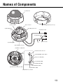
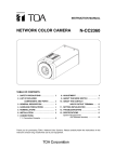
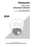
Names of Components
(1) Enclosure
(9) Focus lever
(11) Zoom lever
(2) Mounting bracket (accessory)
(6) Tilting lock screw
(7)Tilt adjustment
seat
(3) Network cable
(4) Alarm I/O cable
(5) Power cable
(8) Panning table
(10) Panning lock screw
(19) Monitor output jack
(12) Heater Unit connector
(15) LED ON/OFF switch button
(16) Access LED (ACT)
(17) Link LED (LINK)
(18) ABF LED (ABF)
(13) INIT button (INIT)
(21) SD memory card error LED
(14) ABF button (ABF)
(20) SD memory card slot
13
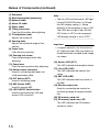
Names of Components (continued)
(1) Enclosure
(2) Mounting bracket (accessory)
(3) Network cable
(4) Alarm I/O cable
(5) Power cable
(6) Tilting lock screw
Fixes the tilt position after adjusting.
(7) Tilt adjustment seat
Adjusts the screen tilt.
(8) Panning table
Adjusts the horizontal angle of the
camera.
(9) Focus lever
Fixes the focus position.
(10) Panning lock screw
Fixes the panning position after
adjusting.
(11) Zoom lever
Fixes the zoom position after adjusting.
(12) Heater output connector
Used for connecting the heater unit
(sold separately) cable.
(13) INIT button (INIT)
Used for initializing setup.
(14) ABF button (ABF)
Used for starting ABF.
(15) LED ON/OFF switch button
Used for turning the link LED and
access LED on and off.
14
.........................................................
Note
• The link LED and the access LED light
if the LED ON/OFF button is ON and
the LED display setting (→ Setup
Manual) on the computer is set to "ON".
The LEDs do not light if the LED ON/
OFF button is OFF or the computer's
LED display settings is set to "OFF".
..............................................................
Important
• In regular operation, set this switch to
off. Lighting of the LEDs may reflect on
the dome and be included in the image
on screen.
(16) Access LED (ACT)
This LED indicates the reception status.
(17) Link LED (LINK)
This LED indicates the network link
status.
(18) ABF LED (ABF)
This LED indicates the busy status of
the ABF.
(19) Monitor output jack
Used for connecting the monitor for
confirming images at camera installation.
(20) SD memory card slot
(21) SD memory card error LED
This LED indicates the SD memory
card error status.
Functions
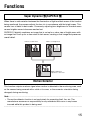
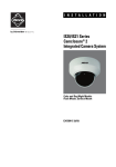
Super Dynamic III (SUPER-D III)
When there is wide variation between the illumination of light and dark areas of the location
being monitored, the camera adjusts the lens iris in accordance with the bright areas. This
causes loss of detail in dark areas. Conversely, adjusting lens brightness for the dark areas
causes brighter areas to become washed out.
SUPER-D III digitally combines an image that is set up for a clear view of bright areas with
an image that is set up for a clear view of dark areas, creating a final image that preserves
overall detail.
Hard to see dark areas
Hard to see bright areas
Digital combination
reproduces a clear view
Motion Detector
This function outputs an alarm signal when motion is detected in the monitoring area, such
as the camera being covered with a cloth or its cover, or the camera's orientation being
changed, during monitoring.
..............................................................................................................................
Note
• The motion detector function is not exclusively for preventing theft, fire, etc. The
manufacturer assumes no responsibility for any accidents that occur or any losses
incurred while this product is being used.
...................................................................................................................................
15
Functions (continued)
Progressive output
Jagged edges that are unique to interlaced cameras and that occur in areas with movement
are corrected by the motion adaptive interlace/progressive conversion function and
converted to progressive images. This allows both still and moving objects to be captured as
well-defined images.
Privacy Zone Setting
The privacy zone function allows you to mask specific areas, such as housing, of a
monitored scene from view.
Auto Back Focus Function
Back focus can be automatically adjusted by operating the buttons on the camera, which
makes installation easier. Back focus can also be adjusted on the PC after the camera is
installed.
When switching between color and black and white images, the back focus is automatically
adjusted and focus deviation is corrected.
Recording to an SD Memory Card
Camera images can be saved to an SD memory card when an alarm occurs.
Images can also be backed up when a network failure occurs.
..............................................................................................................................
Note
• This operation has already been confirmed on the following SD memory cards:
Panasonic SD memory cards (64 MB, 128 MB, 256 MB, 512 MB, 1 GB, 2 GB)
SDHC memory card is not supported.
...................................................................................................................................
16
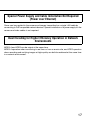
Special Power Supply and Cable Installation Not Required
(Power over Ethernet)
Power can be supplied to the camera and images transmitted on a single LAN cable by
connecting to PoE-compatible network devices. Special installation of a power supply for the
camera and video cables is not required.
Dual Encoding for Higher Efficiency Operation in Network
Environments
MPEG-4 and JPEG can be output at the same time.
MPEG-4 operation when monitoring in real time or from a remote site, and JPEG operation
when recording and verifying images at high quality can both be achieved at the same time
in a network environment.
17
Installation and Connections
Installation Precautions
The following describes how to install the camera.
Before you install and connect the camera, check and prepare the required peripheral
devices and cables.
Before you connect the camera, turn off all devices to be connected, such as this camera
and PC.
Camera Installation Location
Discuss the installation location for the
camera with your retailer, and select a
place that is strong enough for the installation.
• Install the camera on a ceiling
(concrete, etc.) at a location that is
sufficiently strong to support it.
• Install the camera body on the
foundation section of the building or
sections having sufficient bearing
strength.
This camera is for installation under
eaves.
• Do not install it in areas exposed to
direct sunlight or rain.
Never install or use the camera in the
following locations.
• Near a swimming pool or other areas
where chemicals are used.
• Food preparation areas and other
locations where there are large
amounts of steam vapor and oil, in
flammable atmospheres, other special
environments.
• Areas where radiation, X-rays, strong
electric waves, or magnetism is
generated.
18
• At sea, in coastal areas, or in areas
where corrosive gas is being
generated.
• Areas outside of the allowable ambient
operating temperature range
(→ page 47).
• On a motor vehicle, a boat, or other
areas subject to strong vibration.
(This camera is not designed for use on
a vehicle.)
• When installing the camera on a ceiling
of insufficient strength, reinforce the
ceiling.
When not in use, always remove the
unit.
About White Balance
White balance may not be correctly
obtained in the following instances:
• When capturing subjects having
extremely little white or subjects close
to a single color.
• When capturing images outdoors at
dawn or dusk or in low illumination.
• When capturing images having
extremely different color temperatures
(e.g. in color lighting).
About Static Electricity Removal
Before installing the camera, touch a metal
case or other metallic parts with your hand
to remove static electricity from your body.
Do not install in areas subjected to high
amounts of humidity or dust.
Doing so may cause internal components
to damage more easily or malfunction.
Do not wire cables near power lines.
Configure the power supply to the
camera so that it can be turned on and
off.
The camera does not have a power switch,
so configure the power supply to the
camera so that it can be turned on and off.
Screws should be ordered separately.
The camera does not come with screws.
Choose screws in accordance with the
materials and structure of the installation
location.
Electrical Wave Interference
The image may fluctuate near TV or radio
transmission antennas, or near strong
electric or magnetic fields (e.g. motors or
transformers). In this case, setup a specialized thin conduit and pass the cable
through it.
Power Supply by PoE
Use a PoE-compatible (IEEE802.3afcompliant) hub or power supply unit.
Network Connection
Pay attention to the following points when
using the camera's network cable to
connect to a network.
• Wire and install the camera so that the
network will not be influenced by
lightning surges, etc.
• Pan and tilt cannot be used in combination with this camera.
Tightening the Screws
Screws should be tightened sufficiently in
accordance with the materials and
structure of the installation location. After
tightening the screws, visually inspect them
to make sure there is no unevenness and
that each screw is tight.
19
Before Starting Installation
The following procedures are for installing the camera on walls and ceilings.
Important
• The type of screws for the installation depend on the material at the location in which
you will install the bracket (included). However, do not use wood screws or nails.
Metal material: Use M6 or M5 bolts and nuts for mounting.
Concrete wall: Use M6 or M5 anchor bolts for mounting.
(Recommended tightening torque
M4 : 0.8 N·m {8 kgf·cm}
M5 : 1.5 N·m {15 kgf·cm}
M6 : 2.5 N·m {25 kgf·cm})
• Be sure that the arrow on the installation bracket is pointing upwards.
• A pull-out force in excess of 294 N {30 kgf} is required for each screw used in the
installation.
• Use sufficient reinforcement for installations on ceilings that are made of gypsum board
and are weak.
Fixing the bracket (accessory)
• Use the bracket to install the camera on a wall or ceiling that is provided with a hole for
passing the cable through or on exposed piping.
• Screws for fixing the bracket to a wall or ceiling are not provided. Choose screws in
accordance with the materials and structure of the installation location.
• Screws for fixing the camera to the bracket are provided with the camera.
20
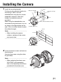
Installing the Camera
1
Install the mounting bracket.
Fix the mounting bracket directly into
the ceiling or wall or into the
imbedded box using the four screws
prepared in advance. (Note that
screws for installation are not
provided.)
When using the imbedded box, we
recommend using two boxes in a row
as shown in the figure below on the
right. (This is to make it easier to pass
the cables through.)
85 mm
Cable pass-through
hole
Cable pass-through
hole
85 mm
51 mm
Center of metal installation bracket
Installation screws x 4
46 mm
..................................................
Note
• When installing the camera
outdoors, waterproof the screws
and screw holes.
83.5 mm
......................................................
Installation screws x 4
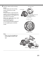
2
Loosen the three screws and remove
the enclosure.
Unscrew the screws using the driver
bit (provided).
..................................................
Note
• When replacing the dome cover
(WV-CW4C, sold separately),
refer to the Operating Instructions
provided with the dome cover.
......................................................
21
Installing the Camera (continued)
3
Unscrew the transportation screw.
Transportation screw
4
Connect the power cable and the
video output cable.
See "Waterproofing Cable Joints" on
page 26.
22
Imbedded box for camera installation
Imbedded box for connecting
cables
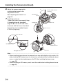
5
Install the camera on the mounting
bracket.
Fix the camera onto the mounting
bracket using the four screws
(provided).
During installation, align the protruding part on the mounting bracket and
the indented part on the camera to fix
the position of the camera.
Make sure to tighten the screws used
for mounting the camera.
(M4:0.78 N·m) {8kgf·cm}
You can keep the camera waterproof
by firmly tightening the installation
screws.
Mounting bracket
Camera body
2 positioning convex parts
(left and right)
2 positioning concave parts
(left and right)
Installation screws
Installation screws
.........................................................................................................................
Note
• When using the embedded box,
run the cable as shown on the
right.
Cable
Imbedded box
Camera
Mounting bracket
..............................................................................................................................
23
Installing the Camera (continued)
6
7
Adjust the camera angle while
monitoring the image on the
adjustment monitor.
See "Adjusting the Camera" on
page 28.
Install the enclosure.
Tighten the screws unscrewed at step
3 using the driver bit (provided).
Align the ▲ mark on the side of the
enclosure with the line on the side of
the bracket. (recommended torque:
0.78 N·m {8 kgf·cm})
75°
Monitor output connector
(mini-jack)
Tilt adjustment
seat
Panning table
Tilt lock screw
Pan lock screw
Line on the side
A
Marking on the side
Installation bracket
Enclosure
Enlarged view of A
.........................................................................................................................
Note
• When installing the enclosure, the camera focus may shift slightly out of position. So,
either hold the ABF button down for at least two seconds before installing the dome
cover, or make the final adjustment on the PC after installing the dome cover.
(→ page 28)
• When installing an SD memory card, insert the card before installing the enclosure.
(→ page 32)
..............................................................................................................................
24
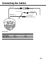
Connecting the Cables
Network cable
RJ-45 female/female conversion connector (included)
Alarm I/O cable
4P alarm cable
(included)
Power cord
(24 V AC/12 V DC)
Brown (Live)
Blue (Neutral)
Green/Yellow (GND)
Power cable
24 V AC
12 V DC
Brown (Live)
Live
Plus
Blue (Neutral)
Neutral
Minus
Green/yellow (GND)
Connect to ground.
25
Connecting the Cables (continued)
Waterproofing Cable Joints
Waterproof the cable to install the camera using exposed wiring, or when installing the
camera under eaves. Though the camera body is waterproof, the cable ends are not
waterproofed.
Follow the procedure below to waterproof the power cables (including Alarm I/O cable) and
LAN cable connections using butyl rubber tape (provided). If vinyl tape other than butyl
rubber tape (provided) is used, water may seep in between the gaps and cause a malfunction.
1
Connect the power cable and the
Alarm I/O cable.
2
Wind butyl rubber tape around the
connections.
3
Wrap butyl rubber tape around the
joint of the LAN cable connector.
2
1
Power cable
3
LAN cable
..............................................................................................................................
Note
• How to wrap butyl rubber tape (provided).
Stretch the tape to about twice its length (see
Stretch about 2x
figure on the right), and wrap it around the cable.
Sufficient waterproofing performance cannot be
obtained unless the tape is sufficiently stretched.
2x
• Waterproof the cable when installing the camera outdoors. The camera body is
waterproof (JIS IP66 or equivalent) only when installation specified in this document and
appropriate waterproofing is conducted correctly. The mounting bracket is not
waterproofed.
...................................................................................................................................
26
Important
• When wiring the cable by exposed wiring, be
sure to use a sleeve to prevent the cable
from being exposed to the direct sunlight.
• Install the camera so that the cable is at the
bottom side of the camera. Draw out the
cable to the side of the mounting fixture, set it
facing down, and then wire it facing up.
Bottom side
• When installing the camera on a wall, install
it so that the water drain groove is facing
down.
Also, do not block the water drain groove.
Blocking the water drain groove will prevent
the dehumidifying element at the rear of the
camera from functioning. Water that builds
up inside the mounting fixture also blocks the
dehumidifying element and this will cause
malfunction.
Water drain groove
Sleeve
27
Adjusting the Camera
1
Adjust the camera angle while
monitoring the image on the
adjustment monitor.
Connect the adjustment monitor
(small LCD monitor, etc.) to the
monitor output terminal, and adjust
the camera angle.
Determine and set the camera angle
while repeating the fine-adjustments
in steps (1), (2) and (3) below.
75°
Monitor output connector
(mini-jack)
(3) Tilt adjustment seat
Panning table
(2) Tilt lock screw
(1) Pan lock screw
(1) Loosen the pan lock screw, and
rotate the camera horizontally to
adjust pan.
(2) Loosen the 2 tilt lock screws, and
rotate the camera vertically to
adjust tilt.
(3) Turn the tilt adjustment seat to
adjust the screen tilt.
(4) When the camera angle is
determined, tighten the pan lock
screw and the tilt lock screws.
..............................................................................................................................
Note
• Also adjust the focus in step 2 during pan and tilt adjustment.
...................................................................................................................................
Important
• Be sure to tighten the panning lock screw (recommended torque: 0.59N·m {6 kgf·cm}).
28
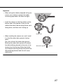
2
Adjust the focus.
Adjust the focus at the same time as
pan and tilt adjustment.
Repeat steps (1) and (2) to adjust the
focus.
(1) Loosen the zoom lock lever, move
the lens to the appropriate view
angle between TELE and WIDE,
and tighten the lever.
(2) Loose the focus lock lever, roughadjust the focus, and tighten the
lever.
(2) Focus lock lever
FAR
TELE
(1) Zoom lock lever
NEAR
WIDE
..............................................................................................................................
Note
• When either the zoom or focus is changed, the other also is changed.
Repeat steps (1) and (2) to adjust. Fine-adjust the focus by ABF as follows.
...................................................................................................................................
3
Press the ABF button.
The ABF LED (→ page 13) lights, the
focus position is displayed at the
bottom of the adjustment monitor
screen, and the back focus is
automatically adjusted.
When connected to a network, the
camera can be operated and checked
from a PC.
..............................................................................................................................
Note
• Pressing and quickly releasing the ABF button immediately starts ABF adjustment.
• If you hold down the ABF button for at least 2 seconds, ABF adjustment is started after
about 3 minutes. Use this for final adjustment after attaching the dome.
...................................................................................................................................
29
Adjusting the Camera (continued)
..............................................................................................................................
Note
• How to Change the View Angle
To change the view angle, turn the zoom lock lever and focus lock lever to adjust the
focus.
• How to Focus (capturing subjects with a self-closing lens)
When the focus has been adjusted with the iris closed (to capture a bright subject), the
subject may be out-of-focus when the iris is opened. So, try to focus the lens in as dark
conditions as possible.
• How to Focus (when capturing subjects in the near infra-red range)
On the [Image/ABF] tab under [Camera setup] on the setup menu, click the [SETUP>>]
button for the back focus setting. The back focus setup dialog box is displayed. Focus
can be adjusted at both the near infra-red area and the visible light area when adjusting
method is set to "AUTO" or "PRESET". (→ Setup Manual)
• How to Use the Varifocal Lens and Zoom Lens
Before adjustment, reset the back focus position, and return the CS mount to its default
position. (→ Setup Manual)
...................................................................................................................................
30
Alarm In/Out Ratings
Terminal Name
ALARM IN
ON
OFF
ALARM OUT
OPEN
CLOSE
AUX OUT
OPEN
CLOSE
DAY/NIGHT IN
ON (black and
white)
OFF (color)
Rating
5 V DC pull-up built in
Short-circuit with GND (necessary
drive current is 1 mA or greater)
Open or 4 V DC to 5 V
Open collector output (internal pullup/maximum drive current 50 mA),
latch/pulse
4 V DC to 5 V
1 V DC maximum
Open collector output (internal pullup/maximum drive current 50 mA)
Open or 4 V DC to 5 V
1 V DC maximum
DC 5 V pull-up built in
Short-circuit with GND (necessary
drive current is 1 mA or greater)
Open or 4VDC to 5V
Remarks
Latch/pulse setting
selectable
Terminal shared with
ALARM OUT. Can be
selected in settings
(Default setting: ALARM
OUT)
..............................................................................................................................
Note
• Check the Operating Instructions (provided) to see if the ratings of sensors and other
external devices are compatible with the camera ratings.
...................................................................................................................................
Pin Arrangement of 4-pin Alarm Cable (accessory)
1 Black
GND
2 Gray
AUX OUT
3 Red
ALARM OUT or DAY/NIGHT IN
4 Green
ALARM IN
31
Handling SD Memory Cards
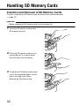
Insertion and Removal of SD Memory Cards
To insert or remove an SD memory card, the dome cover must be removed.
(→ page 21)
Important
• Before inserting an SD memory card, turn the camera off.
1
Insert the SD memory card into the
SD memory card slot.
2
Press the SD memory card in as far
as possible until it is fixed in place.
Your will hear it click into place.
3
To remove an SD memory card, press
it in as far as possible again. You will
hear it click and it will rise up.
Remove the SD memory card.
o
32
Heater Unit
When the heater unit (sold separately) is used, the camera can be used outdoors in lowtemperature environments down to -30ºC (-22ºF). The heater automatically turns on when
the temperature inside the camera falls below about 10ºC (50ºF), and turns off when the
temperature inside rises. The condensation fan alleviates the problem of clouding
(condensation) caused by temperature change in the camera dome caused. Note, however,
that significant condensation caused by sudden temperature change cannot be completely
alleviated.
Important
• The camera image may be influenced when the heater unit is turned on and off.
• Before installing and removing the heater unit, be sure to turn off the camera. The heater
unit is hot while it is turned on. Disconnect the connector from the camera, and wait for
the heater to cool down before removing it.
• When the heater unit is installed and use is started in environments of -10ºC (14ºF) or
below, normal images may not be obtained immediately after the camera is started up.
In this case, wait for the camera to warm up (about 2 hours or more) before turning the
power on again.
• Use 24 V AC or POE to deliver power to a heater unit.
How to Install the Heater Unit
1
2
Remove the enclosure from the
camera, and install the heater unit at
the specified location using the
screws provided.
Connect the heater unit cable to the
connector on the camera body.
Screws for heater unit
provided
2
Heater output
connector
1
Important
• After installing the heater unit, pull the cable through so that it is not pinched while
installing the enclosure. While pulling the cable through, make sure that it does not
become entangled with the movable parts inside the camera.
33
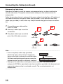
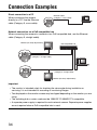
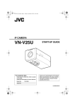
Connection Examples
Direct connection to a PC
When connecting the camera
directly to a PC, use the Ethernet
cable (Category 5, cross cable).
Ethernet cable
(category 5, cross cable)
Network connection via a PoE-compatible hub
When connecting the camera to a network via a PoE-compatible hub, use the Ethernet
cable (Category 5, straight cable).
Monitor (for setup adjustments)
PoE-compatible hub
Ethernet cable
(category 5, straight cable)
Ethernet cable
(category 5, straight cable)
Monitor (for setup adjustments)
Important
• The monitor is intended solely for checking the view angle during installation or
servicing. It is not intended for recording or monitoring images.
• Text displayed on the monitor screen may be clipped depending on the monitor you are
using.
• The switching hub or router used must be 10BASE-T/100BASE-TX-compatible.
• A separate power supply is required for each network camera. Separate power supplies
are not required when a PoE-compatible hub is used.
34
Network Setup
Installing the Software
Be sure to read the "Readme" file in the CD-ROM (provided) before installing the software.
Software in CD-ROM
• Panasonic IP setup software
This software is used to make network settings on the camera. For details, refer to the
following.
• Network Camera View3
To display images on this camera, the viewer software "Network Camera View3" must be
installed. This software can be installed directly from the camera or by double clicking
"nwcv3setup.exe" on the CD-ROM provided, and then following the on-screen
instructions.
Using the Panasonic IP Setup Software to Set Up the
Camera
Use the Panasonic IP Setup Software provided (from here on, IP setup software) to make
network settings on the camera.
When two or more cameras are used, network settings must be made on each camera.
When the network settings cannot be made using the IP setup software, set the cameras
and PC individually in the "Network setup" page in the setup menu. (→ Setup Manual)
Important
• When Windows® XP SP2 is used, an important alert screen regarding security may be
displayed when the IP setup software is started up.
If this happens, click the [Unblock (U)] button.
• To enhance the security, the IP setup software no longer displays the MAC address and
IP address of the target camera when about 20 minutes elapses since the camera was
turned on. Note, however, that when the network settings (IP address, default gateway,
subnet mask, HTTP port number, DHCP setting, user ID, and password) are still at their
defaults when the camera was bought, the MAC address and IP address of the target
camera are displayed even after about 20 minutes elapses since the camera was turned
on.
• The IP setup software cannot be used on different subnets via a router.
35
Network Setup (continued)
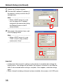
1
2
Launch the IP setup software.
Click the MAC address/IP address of
the camera to set up, and click the [IP
setting] button.
..................................................
Note
2
• When a DHCP server is in use,
you can check the IP address
assigned to the camera by clicking
the [Refresh] button in the IP
setup software.
2
......................................................
3
Enter each of the network items, and
click the [Apply] button.
..................................................
Note
• When a DHCP server is in use,
"DNS" in the IP setup software
can be set to "Auto".
......................................................
3
Important
• It takes about 30 seconds for settings on the camera to complete after clicking the
[Apply] button. The settings will be invalid if the camera is turned off or the Ethernet
cable is disconnected before setting is complete. If this happens, make the settings
again.
• When a firewall (including software) has been installed, allow access of all UDP ports.
36
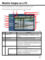
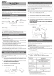
Monitor Images on a PC
The following describes how to monitor images from the camera on a PC.
The following shows the functions of the buttons on the "Live" page.
(1)
(2)
(10)
(11)
(12)
(3)
(4)
(5)
(6)
(13)
(7)
(8)
(9)
(1/3)
No.
Item
Description
(1)
[Camera title]
The camera title entered for "Camera title" on the
[Basic] tab in the Setup menu is displayed. (→ Setup
Manual)
(2)
[Setup] button*1
Click this button to display the setup menu.
(3)
[Live] button
Click this button to display the "Live" page.
(4)
[Multi-screen] buttons
Images from multiple cameras can be displayed on a
multi-screen. To display images from multiple cameras,
set the cameras to display in "Multi-screen setup" in the
setup menu. (→ Setup Manual)
(5)
[Image type]
Click these buttons to display either MPEG-4 or JPEG
images in the main area.
[MPEG-4] button
Click this button to display MPEG-4 images.
When "OFF" is selected for "MPEG-4 transmission" in
the setup menu, the [MPEG-4] button will not be
displayed. (→ Setup Manual)
[JPEG] button
Click this button to display JPEG images.
37
Monitor Images on a PC (continued)
(2/3)
No.
(6)
(7)
(8)
(9)
Item
[Image capture size]
Description
Click these buttons to set the resolution of the main
area to VGA or QVGA.
These buttons will be displayed only when "JPEG" is
selected as the image type.
[VGA] button
Click this button to display images in the main area at
VGA size.
[QVGA] button
Click this button to display images in the main area at
QVGA size.
[ZOOM]
Click the desire button to enlarge the displayed image.
Only the image in the main area is enlarged.
[X1] button
Return to the original display size (1x size).
[X2] button
Display image with 2x size.
[X4] button
Display image with 4x size.
[Brightness]
*2
Click these buttons to adjust the brightness of the
image.
[-] button
The displayed image will be darker.
[0] button
The adjusted brightness will return to the default
brightness.
[+] button
The displayed image will be brighter.
AUX*2
Click these buttons to switch the state of the AUX
connector.
[OPEN] button
Sets the AUX connector to open.
[CLOSE] button
Sets the AUX connector to closed.
(10) [Alarm occurrence
indication] button*2
This button will be displayed and will blink when an
alarm has occurred. When this button is clicked, the
alarm output terminal will be reset and this button will
disappear. (→ Setup Manual)
(11) [Full screen] button
Click this button to display images on a full screen. To
return to the "Live" page, press the [Esc] key, the [F5]
key, or the combination of the [Alt] key and [F4] key on
the PC's keyboard.
38
(3/3)
No.
Item
Description
(12) [One shot] button
Click this button to take a picture (a still picture) and
display it in a newly opened window.
To save the image to PC, right-click on the displayed
image and select "Save".
(13) Main area
Images from the camera are displayed in this area.
The current date and time are displayed at the selected
position using the date and time format set in the setup
menu. (→ Setup Manual)
*1 Only operable by users whose access level is "1. Administrator"
*2 Only operable by users whose access level is "1. Administrator" or "2. Camera control"
when "ON" is selected for "User authentication" or "Host authentication." For further
information about the access level, refer to Setup Manual.
39
Monitor Images on a PC (continued)
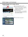
Monitor images from a single camera
• Web browser screen
2
1
2
Launch the web browser on the PC.
3
Press the [Enter] key.
When "ON" is selected for "User Authentication", the window for entering the user name
and password is displayed.
4
Display images from the camera.
Enter the IP address designated using the
Panasonic IP setup software (→ page 35) in
the address box of the browser.
(Example: http://192.168.0.10)
• "Live" page
40
..............................................................................................................................
Note
• When the HTTP port number has been changed from "80", enter "http://IP address of
the camera:port number".
• When the DDNS function has been set to "ON", enter "http://host name registered to
DDNS server.nmdns.net/".
• When this camera is to be used in a local area network, configure the web browser to
bypass the proxy server for the local address.
...................................................................................................................................
Important
• The default user name is "admin" and default password is "12345".
To enhance the security, be sure to change the password for the user name "admin".
(→ Setup Manual)
• When displaying multiple MPEG-4 images on a PC, images sometimes cannot be
displayed depending on the performance of the PC.
For details on the required PC environment, refer to page 6.
Monitor images from multiple cameras
Images from multiple cameras can be displayed on a multi-screen. 4 cameras can be
registered as a group, and camera images for up to 8 cameras (2 groups) can be displayed
simultaneously in a multi-screen. For further information about registering cameras, refer to
the Setup Manual.
Important
• Only JPEG images can be displayed on a multi-screen.
• When the power is turned off or the LAN cable is disconnected when displaying images,
displaying images on a multi-screen from the "Live" page will become unavailable.
41
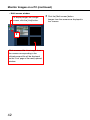
Monitor Images on a PC (continued)
• Multi-screen window
To display images on a single
screen, click the [Live] button.
1
Click a camera title. Live images from
the camera corresponding to the
clicked camera title will be displayed
on the "Live" page of the newly opened
window.
42
1
Click the [Multi-screen] button.
Images from the camera are displayed in
four screens.
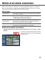
Action at an alarm occurrence
When a "Terminal alarm", "VMD alarm", "Scene change detection alarm" or "Command
alarm" occurs, alarm action is performed according to the setup for that alarm. For further
information about how to set alarms, refer to the Setup Manual.
Alarm type
Terminal alarm
: Alarm action will be performed when the alarm device connected
to the cable is activated.
VMD alarm
: Alarm action will be performed when a change (i.e. motion) is
detected in the image in the set VMD area.
* VMD stands for "Video Motion Detector".
Scene change
detection alarm
: Alarm action will be performed when this camera has been
interfered with, for example, when it has been covered with a
cloth or when its direction has been changed.
Command alarm
: Alarm action will be performed when a Panasonic alarm notice is
received from a connected device via the network.
Action at an alarm occurrence
• Display of the [Alarm occurrence indication] button on the "Live" page (→ Setup
Manual)
The [Alarm occurrence indication] button will be
displayed and will blink on the "Live" page when
an alarm occurs.
43
Action at an alarm occurrence (continued)
Important
• When "Polling(30 sec)" is selected for "Alarm status update mode", the alarm
occurrence indication button will be refreshed in 30-second intervals. For this reason, it
may take a maximum of 30 seconds until the alarm occurrence indication button is
displayed on the "Live" page when an alarm occurs. (→ Setup Manual)
44
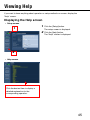
Viewing Help
If you want to know anything about operation or setup methods on screen, display the
"Help" screen.
Displaying the Help screen
• Setup screen
1
1
Click the [Setup] button.
The setup screen is displayed.
2
Click the [Help] button.
The "Help" screen is displayed.
2
• Help screen
Click the desired item to display a
detailed explanation for the
corresponding operation.
45
Troubleshooting
Before requesting service, check the following items.
Also, check the description in the Operating Instructions, Setup Manual.
Contact your dealer if a problem cannot be solved even after checking and trying the
solution or if a problem is not described below.
Symptoms
Check item/remedy
page
AC/DC power supply
• Is the power firmly connected to the power
outlet?
Make sure that it is connected.
—
PoE power supply
46
▲
Camera does not
turn on.
• Is the network cable connected to a PoEcompatible power supply unit by an
Ethernet (Category 5) cable?
Make sure that it is connected.
34
• Some power supply units that can connect
multiple PoE terminal devices are not
supplied with power when the total power
supply limitation is exceeded.
—
• Read the Operating Instructions of the PoE
power supply unit.
—
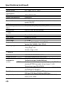
Specifications
• General
Power supply
Power consumption
Ambient operating temperature
Ambient operating humidity
Water Resistance
Monitor output
External I/O terminals
Dimensions
Weight
Finish
24 V AC, 60 Hz, 12 V DC, PoE (IEEE802.3af-compliant)
24 V AC: approx. 8.2 W,
12 V DC: approx. 850 mA,
PoE: approx. 9.2 W (Class 0)
(When heater unit is used)
24 V AC: approx. 16 W,
12 V DC: approx. 920 mA,
PoE: approx. 12 W (Class 0)
-10ºC to +50ºC {14ºF to 122ºF}
(When heater unit is used)
-30ºC to +50ºC {-22ºF to 122ºF} (AC 24 V or PoE)
Less than 90% (non-condensation)
Camera unit: IEC60529 (IP66, Against ingress of water
with harmful effects powerful jetting)
* Only on condition that installation specified in this
document and appropriate waterproofing is conducted
correctly
VBS: 1.0 V [P-P]/75 Ω (NTSC), composite signal, RCA
jack
ALARM IN, ALRM OUT or DAY/NIGHT IN, AUX OUT
159 mm (D) x 153 mm (H) {6-17/64"(D) x 6-1/32"(H)}
Approx. 1.9 kg (including bracket) {4.2 lbs}
Body: aluminum die cast, light silver
Dome: smoke polycarbonate resin
• Camera
Pick-up device
Effective Pixels
Scanning Area
Scanning
Minimum Illumination
(SENSE UP: OFF,
AGC: HIGH, F1.4, WIDE)
Dynamic range
Gain
1/3-inch interline transfer CCD
768 (H) x 494 (V)
4.8 mm (H) x 3.6 mm (V)
2:1 interlace
* Mounted with motion adaptive interlace/progressive
conversion function for network output
1.5 lux {fc} (color), 0.16 lux {fc} (black and white)
(When optional clear dome is used.)
0.6 lux {fc} (color), 0.08 lux {fc} (black and white)
52 dB typ. (Super Dynamic III ON, shutter speed OFF)
ON (LOW), ON (MID), ON (HIGH), OFF
47
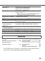
Specifications (continued)
Shutter speed
Electronic sensitivity
enhancement
White balance
Digital noise reduction
Electronic zoom
Camera title
VMD alarm
Scene change detection
alarm
Privacy zone
OFF (1/60), AUTO, 1/100
Max. 32X
ATW1/ATW2/AWC
LOW/HIGH
Max. 3X
Max. 16 character display (alphanumeric characters,
marks) ON/OFF
4 areas settable
ON (LOW), ON (MID), ON (HIGH), OFF
ON/OFF (max. 8 zone settings)
• Lens
Type
Focal length
F number
Focus range
Angle of view
Adjusting angle
2x variable focal lens
f=3.8 mm - 8.0 mm
F1.4 - 1.8, close
∞ - 1.2 m
Horizontal:73.6°(WIDE) - 35.6°(TELE)
Vertical:53.4°(WIDE) - 26.6°(TELE)
Panning range: ±175°
Tilting range: ±75°
Azimuth range: ±160°
• Network
Network
Image resolution
Image
MPEG-4
compression
JPEG
system
Refresh interval
Total bit rate
Supported protocol
48
10BASE-T/100BASE-TX, RJ45 connector
VGA (640 x 480)/QVGA (320 x 240)
Image selection: motion priority/standard/quality priority
Transmission type: Unicast/Multicast
Quality selection: 0 highest quality/1 high quality/2/3/4/5
standard/6/7/8/9 low quality (in ten stages, 0 to 9)
Transmission type: PULL/PUSH
0.1 fps to 30 fps (JPEG frame rate limited at JPEG/MPEG4 simultaneous operation)
Unlimited/64 kbps/128 kbps/256 kbps/
512 kbps/1024 kbps/2048 kbps/4096 kbps
TCP/IP, UDP/IP, HTTP, RTP, FTP, SMTP, DHCP, DNS,
DDNS, NTP, SNMP
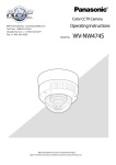
Supported OS
Supported browser
Max. number of connected
cameras
FTP client
Multi-screen
Operation confirmed SD
memory cards (sold
separately)
Windows® 2000 Professional SP4,
Windows® XP Home Edition SP2,
Windows® XP Professional SP2
Internet Explorer® 6.0 SP2,
Internet Explorer® 7.0
* When supported OS is Windows® 2000 Professional
SP4, Microsoft Internet Explorer® 6.0 SP1
8 (depending on conditions)
Alarm image transmission, FTP periodic transmission
Simultaneous display of images from 8 cameras
(4 cameras x 2 groups)
Panasonic
Size: 64 MB, 128 MB, 256 MB, 512 MB, 1 GB, 2 GB
• Optional accessories
Heater unit
Clear dome cover
Ceiling Mount Bracket
WV-CW4H
WV-CW4C
WV-Q169
Weight, approx. 40 g
Weight, approx. 110 g
Weight, approx. 705 g
Accessories
CD-ROM* . . . . . . . . . . . . . . . . . . . . . . .1 pc. Use the following items for installation work.
Operating Instructions (this book) . . . . .1 pc. 4-pin Alarm Cable . . . . . . . . . . . . . . . . . 1 pc.
RJ-45 female-female conversion connector
Warranty Certificate. . . . . . . . . . . . . . . . . . 1
. . . . . . . . . . . . . . . . . . . . . . . . . . . . . . . 1 pc.
Label (MAC address). . . . . . . . . . . . . . .1 pc. Mounting Bracket . . . . . . . . . . . . . . . . . 1 pc.
Driver Bit . . . . . . . . . . . . . . . . . . . . . . . . 1 pc.
Waterproof tape (butyl rubber tape) . . . 1 pc.
* The CD-ROM contains the Panasonic IP Setup Software, viewer software "Network
Camera View3", and the Operating Manual/Setup Manual (PDF).
49
Panasonic System Solutions Company,
Unit Company of Panasonic Corporation of North America
Security Systems
www.panasonic.com/security
For customer support, call 1.877.733.3689
Executive Office: Three Panasonic Way 2H-2, Secaucus, New
Jersey 07094
Zone Office
Eastern: Three Panasonic Way, Secaucus, New Jersey 07094
Central: 1707 N. Randal Road, Elgin, IL 60123
Southern: 1225 Northbrook Parkway, Suwanee, GA 30024
Western: 6550 Katella Ave., Cypress, CA 90630
© 2007 Matsushita Electric Industrial Co., Ltd. All Rights Reserved.
Panasonic Canada Inc.
5770 Ambler Drive,Mississauga,
Ontario, L4W 2T3 Canada (905)624-5010
http://www.panasonic.ca
Panasonic Sales Company
Division of Panasonic Puerto Rico Inc.
San Gabriel Industrial Park 65th Infantry Ave. KM. 9.5 Carolina
P.R. 00985(809)750-4300
AM0307-2057
3TR005032CAA
Printed in Japan