1
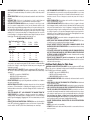
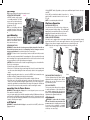
Инструкция
DeWALT DW745
Перейти в карточку товара
8 800 775 98 98
л чит т нич
ю н льт цию.
гл т чн . Б з вы дны
www.sotmarket.ru
д бн я инф м ция
тзывы, бз ы и
т в
ы
,
Before returning this product call
1-800-4-DEWALT
IF YOU SHOULD EXPERIENCE A PROBLEM WITH YOUR
DEWALT PURCHASE,
call 1-800-4-DEWALT
IN MOST CASES, A DEWALT REPRESENTATIVE CAN RESOLVE
YOUR PROBLEM OVER THE PHONE.
IF YOU HAVE A SUGGESTION OR COMMENT, GIVE US A CALL.
YOUR FEEDBACK IS VITAL TO THE SUCCESS OF
DEWALT’S QUALITY IMPROVEMENT PROGRAM.
Questions? See us on the World Wide Web at www.dewalt.com
INSTRUCTION MANUAL
GUIDE D'UTILISATION
MANUAL DE INSTRUCCIONES
INSTRUCTIVO DE OPERACIÓN, CENTROS DE SERVICIO Y PÓLIZA
DE GARANTÍA. ADVERTENCIA: LÉASE ESTE INSTRUCTIVO ANTES
DE USAR EL PRODUCTO.
DW745 Heavy-Duty 10" (254 mm) Job Site Table Saw
Scie circulaire à table de chantier robuste avec lame de 254 mm (10 po), DW745
Sierra de banco para el lugar de trabajo de 254 mm (10") de alta resistencia DW745
The definitions below describe the level of severity
for each signal word. Please read the manual and pay
attention to these symbols.
DANGER: Indicates an imminently hazardous
situation which, if not avoided, will result in death or
serious injury.
WARNING: Indicates a potentially hazardous
situation which, if not avoided, could result in death
or serious injury.
CAUTION: Indicates a potentially hazardous
situation which, if not avoided, may result in minor or
moderate injury.
CAUTION: Used without the safety alert symbol
indicates a potentially hazardous situation which, if
not avoided, may result in property damage.
A
GROUNDED
OUTLET
BOX
B
GROUNDING PIN
C
D
GROUNDING
MEANS
ADAPTER
GROUNDING PIN
NOTE: In Canada, the use of a temporary adapter is not permitted by the Canadian
Electric Code.
DANGER: IN ALL CASES, MAKE CERTAIN THAT THE RECEPTACLE IN QUESTION IS
PROPERLY GROUNDED. IF YOU ARE NOT SURE, HAVE A QUALIFIED ELECTRICIAN
CHECK THE RECEPTACLE.
SAVE THESE INSTRUCTIONS
General Safety Rules
WARNING: Read all instructions before operating product. Failure to follow all
instructions listed below may result in electric shock, fire and/or serious injury.
Double Insulation
If saw is of double-insulated construction, read the following instructions.
Double insulated tools are constructed throughout with two separate
layers of electrical insulation or one double thickness of insulation between
you and the tool’s electrical system. Tools built with this insulation system
are not intended to be grounded. As a result, your tool is equipped with a
two prong plug which permits you to use extension cords without concern
for maintaining a ground connection. Repair or replace damaged or worn
cord immediately
NOTE: Double insulation does not take the place of normal safety precautions when operating this tool. The insulation system is for added protection against injury resulting from a
possible electrical insulation failure within the tool.
SAVE THESE INSTRUCTIONS
WARNING: FOLLOW ALL WIRING CODES and recommended electrical connections
to prevent shock or electrocution.
Grounding Instructions
If saw is of grounded construction, read the following instructions.
DANGER: SHOCK HAZARD. THIS MACHINE MUST BE GROUNDED WHILE IN USE.
SERIOUS INJURY COULD RESULT.
ALL GROUNDED, CORD-CONNECTED MACHINES
In the event of a malfunction or breakdown, grounding provides a path of least resistance for electric current to reduce the risk of electric shock. This machine is equipped
with an electric cord having an equipment-grounding conductor and a grounding plug.
The plug must be plugged into a matching outlet that is properly installed and grounded
in accordance with all local codes and ordinances. Do not modify the plug provided - if
it will not fit the outlet, have the proper outlet installed by a qualified electrician. Improper
connection of the equipment-grounding conductor can result in risk of electric shock.
The conductor with insulation having an outer surface that is green with or without yellow stripes is the equipment-grounding conductor. If repair or replacement of the electric
cord or plug is necessary, do not connect the equipment-grounding conductor to a live
terminal. Check with a qualified electrician or service personnel if the grounding instructions are not completely understood, or if in doubt as to whether the machine is properly
grounded. Use only three-wire extension cords that have three-prong grounding type
plugs and matching three-conductor receptacles that accept the machine’s plug, as
shown in Fig. A. Repair or replace damaged or worn cord immediately.
POLARIZED PLUGS
To reduce the risk of electric shock, this equipment has a polarized plug (one blade is wider
than the other). This plug will fit in a polarized outlet only one way. If the plug does not fit
fully into the outlet, reverse the plug. If it still does not fit, contact a qualified electrician to
install the proper outlet. Do not change the plug in any way.
Important Safety Instructions
• TO REDUCE THE RISK OF KICKBACK AND OTHER INJURIES, KEEP GUARDS IN
PLACE and in working order at all times.
• REMOVE ADJUSTING KEYS AND WRENCHES. Form habit of checking to see that
keys and adjusting wrenches are removed from spindle before turning tool on. Tools,
scrap pieces, and other debris can be thrown at high speed, causing injury.
• KEEP WORK AREA CLEAN. Cluttered areas and benches invite accidents.
• DO NOT USE THE MACHINE IN A DANGEROUS ENVIRONMENT. The use of power
tools in damp or wet locations or in rain can cause shock or electrocution. Keep your
work area well-lit to avoid tripping or placing arms, hands, and fingers in danger.
• KEEP CHILDREN AWAY. All visitors should be kept at a safe distance from work area.
Your shop is a potentially dangerous environment.
GROUNDED, CORD-CONNECTED MACHINES INTENDED FOR USE ON A SUPPLY
CIRCUIT HAVING A NOMINAL RATING LESS THAN 150 VOLTS
If the machine is intended for use on a circuit that has an outlet that looks like the one
illustrated in Fig. A, the machine will have a grounding plug that looks like the plug illus1
English
trated in Fig. A. A temporary adapter, which looks like the adapter illustrated in Fig. B,
may be used to connect this plug to a matching two-conductor receptacle as shown in
Fig. B if a properly grounded outlet is not available. The temporary adapter should be
used only until a properly grounded outlet can be installed by a qualified electrician. The
green-colored rigid ear, lug, and the like, extending from the adapter must be connected
to a permanent ground such as a properly grounded outlet box. Whenever the adapter
is used, it must be held in place with a metal screw.
Definitions: Safety Guidelines
English
• MAKE WORKSHOP CHILDPROOF with padlocks, master switches, or by removing
starter keys. The unauthorized start-up of a machine by a child or visitor may result in
injury.
• DO NOT FORCE TOOL. It will do the job better and be safer at the rate for which it was
designed.
• USE RIGHT TOOL. Don’t force tool or attachment to do a job for which it was not
designed. Using the incorrect tool or attachment may result in personal injury.
• USE PROPER EXTENSION CORD. Make sure your extension cord is in good condition. If your product is equipped with a cord set, use only three-wire extension cords
that have three-prong grounding-type plugs and three-pole receptacles that accept the
tool’s plug. When using an extension cord, be sure to use one heavy enough to carry
the current your product will draw. An undersized cord will cause a drop in line voltage
resulting in loss of power and overheating. The following table shows the correct size
to use depending on cord length and nameplate ampere rating. If in doubt, use the next
heavier gage. The smaller the gage number, the heavier the cord.
•
•
•
•
•
•
• USE RECOMMENDED ACCESSORIES. Use only accessories that are recommended
by the manufacturer for your model. Accessories that may be suitable for one tool may
be hazardous when used on another tool. Consult the instruction manual for recommended accessories. The use of improper accessories may cause risk of injury to
persons.
• NEVER STAND ON TOOL. Serious injury could occur if the tool is tipped or if the cutting tool is unintentionally contacted.
• CHECK FOR DAMAGED PARTS. Before further use of the tool, a guard or other part
that is damaged should be carefully checked to determine that it will operate properly
and perform its intended function—check for alignment of moving parts, binding of
moving parts, breakage of parts, mounting and any other conditions that may affect
its operation. A guard or other part that is damaged should be properly repaired or
replaced. Do not use tool if switch does not turn it on and off. Damaged parts can cause
further damage to the machine and/or personal injury.
• DIRECTION OF FEED. Feed work into a blade or cutter against the direction of rotation
of the blade or cutter only.
• NEVER LEAVE TOOL RUNNING UNATTENDED. TURN POWER OFF. Don’t leave
tool until it comes to a complete stop. Serious injury can result.
• DO NOT OPERATE ELECTRIC TOOLS NEAR FLAMMABLE LIQUIDS OR IN
GASEOUS OR EXPLOSIVE ATMOSPHERES. Motors and switches in these tools may
spark and ignite fumes.
• STAY ALERT, WATCH WHAT YOU ARE DOING, AND USE COMMON SENSE. DO
NOT USE THE MACHINE WHEN YOU ARE TIRED OR UNDER THE INFLUENCE
OF DRUGS, ALCOHOL, OR MEDICATION. A moment of inattention while operating
power tools may result in serious injury.
• DO NOT ALLOW FAMILIARITY (gained from frequent use of your saw) TO
REPLACE SAFETY RULES. Always remember that a careless fraction of a second is
sufficient to inflict severe injury.
MINIMUM GAGE FOR CORD SETS
Volts Total Length of Cord in Feet
120V
0-25
26-50
51-100
101-150
240V
0-50
51-100
101-200
201-300
Ampere Rating
More Not more
AWG
Than Than
0 - 6
18
16
16
14
6 - 10
18
16
14
12
10 - 12
16
16
14
12
12 - 16
14
12
Not Recommended
WEAR PROPER APPAREL. No loose clothing, gloves, neckties, rings, bracelets, or
other jewelry to get caught in moving parts. Non-slip footwear is recommended. Wear
protective hair covering to contain long hair. Air vents may cover moving parts and
should also be avoided.
ALWAYS USE SAFETY GLASSES. Everyday eyeglasses are NOT safety glasses.
Also use face or dust mask if cutting operation is dusty. ALWAYS wear certified safety
equipment:
• ANSI Z87.1 eye protection (CAN/CSA Z94.3)
• ANSI S12.6 (S3.19) hearing protection
• NIOSH/OSHA/MSHA respiratory protection.
DO NOT OVERREACH. Keep proper footing and balance at all times. Loss of balance
may cause personal injury.
MAINTAIN TOOLS WITH CARE. Keep blades sharp and clean for best and safest
performance. Follow instructions for lubricating and changing accessories. Poorly
maintained blades and machines can further damage the blade or machine and/or
cause injury.
TURN THE MACHINE “OFF”, AND DISCONNECT THE MACHINE FROM THE
POWER SOURCE before installing or removing accessories, before adjusting or
changing set-ups, when making repairs or changing locations. Do not touch the plug’s
metal prongs when unplugging or plugging in the cord. An accidental start-up can cause
injury.
REDUCE THE RISK OF UNINTENTIONAL STARTING. Make sure that the switch is
in the “OFF” position before plugging in the power cord. In the event of a power failure,
move the switch to the “OFF” position. An accidental start-up can cause injury.
Additional Safety Rules for Table Saws
WARNING: ALWAYS USE SAFETY GLASSES. Everyday eyeglasses are NOT safety
glasses. Also use face or dust mask if cutting operation is dusty. All users and bystanders
MUST ALWAYS wear certified safety equipment:
• ANSI Z87.1 eye protection (CAN/CSA Z94.3),
• ANSI S12.6 (S3.19) hearing protection,
• NIOSH/OSHA/MSHA respiratory protection.
• AVOID AWKWARD POSITIONS, where a sudden slip could cause a hand to move into
a saw blade.
• NEVER REACH IN BACK OF, OR AROUND, THE CUTTING TOOL with either hand
to hold down the work piece.
• KEEP ARMS, HANDS AND FINGERS AWAY from the blade to prevent serious injury.
• USE A PUSH STICK OR PUSH BLOCK THAT IS APPROPRIATE TO THE APPLICATION TO PUSH WORK PIECES THROUGH THE SAW. A push stick is a wooden or
non-metallic stick, usually homemade, that should be used whenever the size or shape
of the work piece would cause you to place your hands within six inches of the blade.
Use hold-downs, jigs, fixtures or feather boards to help guide and control the
work piece when the guard cannot be used. Use saw-blade guard and splitter for
every operation for which it can be used, including all through sawing.
• DO NOT PERFORM RIPPING, CROSSCUTTING OR ANY OTHER OPERATION
FREEHAND.
• NEVER reach around or over saw blade.
• STABILITY. Make sure the table saw is firmly mounted to a secure surface before use
and does not move.
2
SAW BLADE GUARD AND SPLITTER
Your table saw is equipped with a blade guard and splitter assembly that covers the blade
and prevents accidental contact. The splitter is a flat plate that fits into the cut made by the
saw blade and effectively fights kickback by lessening the tendency of the blade to bind
in the cut. The splitter can only be used when making through cuts that sever the wood.
When making rabbets and other cuts that make less than through cuts, the blade guard
and splitter assembly must be removed from the saw. Two anti-kickback pawls are located
on the sides of the splitter that allow the wood to pass through the blade in the cutting
direction but lock it if it tries to move backwards toward the operator.
MAKING A PUSH STICK (Inside Back Cover)
• In order to operate your table saw safely you must use a push stick whenever the size
or shape of the work piece would cause your hands to be within 6" (152 mm) of the saw
blade or other cutter. A push stick is included with this saw.
• No special wood is needed to make additional push-sticks as long as it’s sturdy and
long enough. A length of 12" (305 mm) is recommended with a notch that fits against
the edge of the work piece to prevent slipping. It’s a good idea to have several push
sticks of the same length [12" (305 mm)] with different size notches for different work
piece thicknesses.
• See the inside back cover for a picture of a push stick. The shape can vary to suit your
own needs as long as it performs its intended function of keeping your hands away from
the blade.
KICKBACKS
How to Avoid Them and Protect Yourself from Possible Injury
a. Be certain that the rip fence is parallel to the saw blade.
b. Do not rip by applying the feed force to the section of the work piece that will become
the cut-off (free) piece. Feed force when ripping should always be applied between the
saw blade and the fence; use a push stick for short work, 6" (152 mm) wide or less. For
less than 2" (51 mm) wide, you must use a special fixture.
c. Keep saw blade guard, splitter and anti-kickback teeth in place and operating properly.
Keep teeth sharp. If teeth are not operational, return your unit to the nearest authorized
DEWALT service center for repair. The splitter must be in alignment with the saw blade
and the teeth must stop a kickback once it has started. Check their action before ripping
by pushing the wood under the anti-kickback teeth. The teeth must prevent the wood
from being pulled toward the front of the saw.
d. Plastic and composition (like hardboard) materials may be cut on your saw. However,
since these are usually quite hard and slippery, the anti-kickback pawls may not stop
a kickback. Therefore, be especially attentive to following proper set up and cutting
procedures for ripping.
e. Use saw blade guard and splitter for every operation for which it can be used, including
all through-sawing.
f. Push the work piece past the saw blade prior to release.
g. NEVER rip a work piece that is twisted or warped, or does not have a straight edge to
guide along the fence.
h. Use featherboards when the anti-kickback device or the guard and splitter cannot be
used.
i. NEVER saw a large work piece that cannot be controlled.
j. NEVER use the fence as a guide or length stop when crosscutting.
k. NEVER saw a work piece with loose knots, flaws, nails or other foreign objects.
l. NEVER rip a work piece shorter than 10".
WARNING: Some dust created by power sanding, sawing, grinding, drilling, and other
construction activities contains chemicals known to the State of California to cause cancer,
birth defects or other reproductive harm. Some examples of these chemicals are:
TERMS: THE FOLLOWING TERMS WILL BE USED THROUGHOUT THE MANUAL
AND YOU SHOULD BECOME FAMILIAR WITH THEM.
• Through-sawing refers to any cut that completely severs the work piece.
• Push Stick refers to a wooden stick, usually homemade, that is used to push small
work piece through the saw and keeps the operator’s hands clear of the blade.
• Kickback occurs when the saw blade binds in the cut and violently thrusts the work
piece back toward the operator.
• Freehand refers to cutting without the use of a miter gauge or rip fence or any other
means of guiding or holding the work piece other than the operator’s hand.
3
English
• NEVER CUT FERROUS METALS (those with any iron or steel content), CEMENT
BOARD OR MASONRY. Certain man-made materials have special instructions for
cutting on table saws. Follow the manufacturer’s recommendations at all times.
Damage to the saw and personal injury may result.
• THE PROPER THROAT PLATE MUST BE IN PLACE AT ALL TIMES to reduce the
risk of a thrown work piece and possible injury.
• USE THE CORRECT SAW BLADE FOR THE INTENDED OPERATION. The blade
must rotate toward the front of the saw. Always tighten the blade arbor nut securely.
Before use, inspect the blade for cracks or missing teeth. Do not use a damaged
blade.
• NEVER ATTEMPT TO FREE A STALLED SAW BLADE WITHOUT FIRST TURNING
THE MACHINE OFF AND DISCONNECTING THE SAW FROM THE POWER
SOURCE. If a work piece or cut-off piece becomes trapped inside the guard, turn saw
off and wait for blade to stop before lifting the guard and removing the piece.
• NEVER START THE MACHINE with the work piece against the blade to reduce the risk
of a thrown work piece and personal injury.
• NEVER run the work piece between the fence and a molding cutterhead to reduce the
risk of a thrown work piece and personal injury.
• NEVER have any part of your body in line with the path of the saw blade. Personal
injury will occur.
• NEVER PERFORM LAYOUT, ASSEMBLY OR SET-UP WORK on the table/work area
when the machine is running. A sudden slip could cause a hand to move into the blade.
Severe injury can result.
• CLEAN THE TABLE/WORK AREA BEFORE LEAVING THE MACHINE. Lock
the switch in the “OFF” position and disconnect from the power source to prevent
unauthorized use.
• DO NOT leave a long board (or other work piece) unsupported so the spring of
the board causes it to shift on the table resulting in loss of control and possible
injury. Provide proper support for the work piece, based on its size and the type of
operation to be performed. Hold the work firmly against the fence and down against the
table surface.
• DO NOT OPERATE THIS MACHINE until it is completely assembled and installed
according to the instructions. A machine incorrectly assembled can cause serious
injury.
• OBTAIN ADVICE from your supervisor, instructor, or another qualified person if you are
not thoroughly familiar with the operation of this machine. Knowledge is safety.
• ADDITIONAL INFORMATION regarding the safe and proper operation of power
tools (i.e., a safety video) is available from the Power Tool Institute, 1300 Sumner
Avenue, Cleveland, OH 44115-2851 (www.powertoolinstitute.com). Information is also
available from the National Safety Council, 1121 Spring Lake Drive, Itasca, IL 601433201. Please refer to the American National Standards Institute ANSI 01.1 Safety
Requirements for Woodworking Machines and the U.S. Department of Labor OSHA
1910.213 Regulations.
English
been damaged during shipping. If any parts are missing or damaged, contact your dealer to
replace them before attempting to assemble the tool.
Refer to Figure 2 for the loose items and hardware included with the saw:
1. Rip fence
2. Arbor wrench and spindle wrench (attached to saw base)
3. Blade guard
4. Miter gauge
5. Push stick (attached to saw base)
6. Extra guard shims
• lead from lead-based paints,
• crystalline silica from bricks and cement and other masonry products, and
• arsenic and chromium from chemically-treated lumber (CCA).
Your risk from these exposures varies, depending on how often you do this type of work.
To reduce your exposure to these chemicals: work in a well-ventilated area, and work with
approved safety equipment, such as those dust masks that are specially designed to filter
out microscopic particles.
• Avoid prolonged contact with dust from power sanding, sawing, grinding,
drilling, and other construction activities. Wear protective clothing and wash
exposed areas with soap and water. Allowing dust to get into your mouth, eyes, or
lay on the skin may promote absorption of harmful chemicals.
WARNING: Use of this tool can generate and/or disburse dust, which may cause
serious and permanent respiratory or other injury. Always use NIOSH/OSHA approved
respiratory protection appropriate for the dust exposure. Direct particles away from face
and body. Always operate tool in well-ventilated area and provide for proper dust removal.
Use dust collection system wherever possible.
FEATURES (Fig. 3, 4)
Examine Figures 3 and 4 to become familiar with the saw and its various parts. The
following sections on assembly and adjustments will refer to these terms and you must know
what and where the parts are.
FIG. 3
SAVE THESE INSTRUCTIONS FOR FUTURE USE
A
Specifications
15 AMP
Miter Angle
Bevel Angle
Blade Size
Max. Cut Depth
Max. Cut Depth
RPM, no load
FIG. 1
Q
C
D
E
B
G
F
60° L and R
0° to 45° L
10" (254 mm)
0° Bevel
3-1/8" (79 mm)
45° Bevel
2-1/4" (57 mm)
3850
P
O
H
M
FIG. 2
I
N
L
N
J
K
6
Unpacking
FIGURE 3
A. Table
B. Miter gauge
C. Blade
D. Blade guard
E. Fence
F. Fence rails
G. Rip fence front latch
H. Fine adjustment knob
I. Blade height adjustment wheel
WARNING: To reduce the risk of injury, do not connect the machine to the power source
until the machine is completely assembled and you read and understand the entire
instruction manual.
Open the box and slide the saw out, as shown in Figure 1. Carefully unpack the table saw
and all loose items from the carton. Examine all parts to make sure that parts have not
FIGURE 4
R. Rip fence rear latch
S. Dust collection port
T. Dust shroud
U. Push stick
4
J.
K.
L.
M.
N.
O.
P.
Q.
Bevel lock lever
ON/OFF switch
Rip fence indicator
Adjustable feet
Mounting holes
Cord wrap
Handle
Anti-kickback teeth
V. Arbor wrench, spindle wrench
W. Rail lock lever
FIG. 4
R
P
W
V
M
U
Rip Fence
M
N
T
S
The rip fence can be installed on the left or right side of your table saw.
N
FIG. 7
FIG. 8
G
ASSEMBLY
WARNING: Shock Hazard. To reduce the risk of serious personal injury, turn
unit off and disconnect machine from power source before attempting to move it,
change accessories or make any adjustments.
BB
ASSEMBLE YOUR SAW IN THE FOLLOWING ORDER
1. Rip fence (NOTE: Adjust rip scale before proceeding; refer to Rip Scale Adjustment.)
2. Blade guard
3. Push stick
4. Miter gauge (if required for application)
5. Blade height adjustment crank
Tools needed for assembly include a Phillips screwdriver and the wrenches included with
your saw.
FIG. 5
Blade
ATTACHING AND REPLACING
THE BLADE
1. Raise the saw blade arbor to its
maximum height by turning the
blade height adjustment wheel (I)
clockwise.
2. If replacing the blade, remove the
blade guard (D) and throat plate
(X) prior to installing the new blade.
(Refer to To Remove Blade Guard
and To Remove Throat Plate.)
NOTE: It may be easier to change
the blade with the saw blade
beveled to 45˚.
AA
BB
AA
TO ASSEMBLE THE RIP FENCE (FIG. 7, 8)
1. Align the locator screw (AA) on the fence
rail (F) with the fence head slot and align
the latch (G) with the opening (BB).
2. Secure the rip fence by snapping the
latches onto the rails as shown in Figure
8. Be sure to snap both front (G) and rear
(R) latches in place.
C
Y
Throat Plate (Fig. 9)
TO REMOVE THE THROAT PLATE
1. Remove the throat plate (X) by turning
the cam lock screw (CC) in the front
middle 1/4 turn as shown.
2. Insert the hooked end of the arbor nut
wrench into the slot on the plate and pull
it up and forward to expose the inside of
the saw.
Z
5
FIG. 9
X
Q
CC
X
English
3. Remove the arbor nut (Y) and outer washer (Z) and set aside.
4. Place the blade (C) on the arbor making sure the FIG. 6
teeth of the blade point downward and toward the
front of the saw.
5. Place the outer washer (Z) against the blade,
raised side out and tighten the arbor nut against
the washer as far as possible by hand. Ensure that
the outer washer and arbor nut are free of dust and
debris before installing.
6. To further tighten the arbor nut (Y), use the open
ended spindle wrench (supplied) to keep the
Y
spindle from rotating (Fig 6).
7. Use the arbor wrench (supplied) to hold the nut
and tighten it by turning it clockwise. Reposition the
wrench on the arbor nut and repeat as necessary until the nut and washer are securely
fastened against the blade (Fig. 6).
D
English
4. Press the wing nut toward the guard mechanism and pull the guard out of the saw.
NOTE: For ease of use, the blade guard can be inserted directly into the saw without pushing the nut in toward the guard mechanism. However, the wing nut must still be tightened.
TO ATTACH THE THROAT PLATE
1. Align the throat plate as shown in Figure 9, and insert the tabs on the back of the throat
plate into the holes on the back of the table.
2. Rotate cam out of the way until the front of throat plate drops into place. Secure by
rotating 1/4 turn (when cam lock is under the table holding the throat plate in place) as
shown in Figure 9.
3. The throat plate includes four adjustment screws which raise or lower the throat plate.
When properly adjusted, the front of the throat plate should be flush or slightly below
the surface of the table top and secured in place. The rear of the throat plate should be
flush or slightly above the table top.
CAUTION: To reduce the risk of serious personal injury, the throat plate must be in place
at all times.
Blade Guard
TO ATTACH THE BLADE GUARD
1. Remove the throat plate. (Refer to Throat
Plate.)
2. Raise the saw blade arbor to its maximum
height by turning the blade height adjustment
wheel (I) clockwise.
3. Loosen the wing nut (DD) [minimum of three
complete turns].
4. Insert the splitter (EE) into the locking mechanism on the saw as shown in Figure 10A until
the guard snaps into place. Pull up on the
guard to make sure it is secure in the mechanism.
5. Tighten the wing nut against the locking
mechanism.
IMPORTANT: THE BLADE GUARD SHOULD
BE IN PLACE FOR ALL POSSIBLE CUTS.
WARNING: Before connecting the table saw to
the power source or operating the saw, always
inspect the guard and splitter for proper alignment and clearance with saw blade. Check
alignment after each change of bevel angle.
When properly aligned, the splitter will be in line
with the blade at both table top level, and at the
top of the blade. Using a straight edge, ensure
that the blade is aligned with the splitter as shown
in Figure 10B. With power disconnected, operate
the blade tilt and height adjustments through the
extremes of travel and ensure the guard clears the
blade in all operations and that the anti-kickback
teeth are functioning. Replace the throat plate.
TO ADJUST THE BLADE GUARD
The blade guard and splitter are aligned at the factory. In the event that additional adjustment is needed, extra guard shims have been provided to adjust the alignment.
1. Raise the blade (C) to its highest level.
2. Remove the blade guard (D) and blade. (Refer to To Attach the Blade Guard under
Blade Guard.)
FIG. 11
GG
FIG. 10A
GG
D
EE
DD
FF
FF
HH
3. Remove the two screws (FF) holding the guard retainer (GG) using a 5 mm hex wrench
(HH), as shown in Figure 11.
4. Add or remove shims (II) to align the splitter to the blade.
FIG. 12
II
GG
5. Reassemble, torquing the screws securely in place. Make sure the splitter is aligned
properly to the blade. (Refer to To Attach the Blade Guard under Blade Guard.)
FIG. 10B
Push Stick
WARNING: To reduce the risk of serious personal injury, have push stick ready to use
before starting cut.
TO REMOVE THE BLADE GUARD
1. Remove the throat plate. (Refer to Throat
Plate.)
2. Insert the hooked end of the arbor nut wrench
into the slot on the plate and pull it up and
forward to expose the inside of the saw.
3. Flip the guard back and loosen the wing nut
beside the guard clamp mechanism.
TO ATTACH THE PUSH STICK (FIG. 4)
The push stick included with the DW745 mounts to the right of the saw under the blade
wrench storage. To attach the push stick to the saw, align the slots in the handle of the stick
with the mounting pins on the saw housing.
6
NOTE: A large auxiliary miter gauge face may be used.
TO ATTACH THE MITER GAUGE
The DW745 includes a miter gauge
for crosscutting materials. The miter
gauge can be used by insertion into
one of the two miter gauge slots (JJ)
in the table top (Fig. 13).
NOTE: See crosscutting and bevel
crosscutting instructions before performing these operations on the table
saw.
FIG. 13
RAIL LOCK LEVER (FIG. 4)
The rail lock lever (W) locks the fence in place preventing movement during cutting. To lock the rail
lever, push it down and toward the rear of the saw. To
unlock, pull it up and toward the front of the saw.
NOTE: When ripping, always lock the rail lock lever.
Bench Mounting
NOTE: A portable table saw stand is
designed for use with this saw and is
available at a local DEWALT dealer or
service center at extra cost.
KK
Rip Fence Operation
JJ
K
WORK SUPPORT EXTENSION
Your table saw is equipped with a work support extension to support work that extends
beyond the saw table. To use the work support extension, rotate it as shown in Figure 15.
When not in use, the work support extension retracts, as shown in Figure 16.
NOTE: Retract the work support extension whenever working over the table.
TO BENCH MOUNT SAW
WARNING: To reduce the risk of serious personal injury, turn unit off and disconnect machine from power source before attempting to move it, change accessories
or make any adjustments. An accidental start-up can cause injury.
CAUTION: To reduce the risk of personal injury, make sure table saw is firmly mounted
before use.
The table saw must be mounted firmly. Four mounting holes (N) are provided in the metal
frame for mounting. We strongly recommend that these holes be used to anchor the table
saw to your workbench or other rigid, stationary work support.
CAUTION: Ensure that the surface is stable enough that large pieces of material will not
cause it to tip over during use.
1. Center the saw on the desired, stable work surface.
2. Drive four 3-1/2" (88.9 mm) long screws through the holes in the metal frame. Make
sure the screws extend through the frame and securely attach to the supporting work
surface.
If marring the supporting work surface is a concern, the DW745 can be mounted to scrap
wood which can then be clamped onto the desired work surface.
1. Cut a piece of 3/4" (19 mm) plywood to fit beneath the footprint of the saw.
2. Screw the saw to the plywood and clamp the overhang of the plywood to the work
surface. If the screws protrude through the plywood base, set it on two scrap pieces of
material of equal thickness and attach them to the edges of the plywood to hold the saw
further off of the work surface and prevent the screws from marring the surface.
FIG. 15
FINE ADJUSTMENT KNOB (FIG. 17)
The fine adjustment knob (H) allows smaller
adjustments when setting the fence. Before
adjusting, be sure the rail lock lever is in its
up or unlocked, position.
FIG. 16
FIG. 17
NN
RIP SCALE POINTER
The rip scale pointer will need to be adjusted
for proper performance of the rip fence if the
user switches between thick and thin kerf
blades. Refer to Rip Scale Adjustment under
Adjustments for alignment instructions.
Connecting Saw to Power Source
WARNING: To reduce the risk of injury, before connecting saw to power source, make
sure the switch is in the OFF position.
Be sure your power supply agrees with the nameplate marking. AC Only means that your
saw will operate on alternating current only. A voltage decrease of 10 percent or more will
cause a loss of power and overheating. All DEWALT tools are factory tested. If this tool does
not operate, check the power supply.
Adjustments
WARNING: To reduce the risk of injury,
turn unit off and disconnect machine from
power source before installing and removing
accessories, before adjusting or changing
set-ups or when making repairs. An accidental start-up can cause injury.
On-Off Switch
WARNING: To reduce the risk of injury, be sure switch is in the OFF position before
plugging machine in.
7
H
English
Lift the ON/OFF switch (K) paddle up to turn your saw ON and push it down to turn your
saw OFF.
FIG. 14
A hole (KK) is provided in the switch for insertion of a
padlock with a removable shank to lock the saw off
(Fig. 14).
NOTE: A conventional padlock will not fit.
Miter Gauge
English
NOTE: Your saw is fully and accurately adjusted at the factory at the time of manufacture. If
readjustment due to shipping and handling or any other reason is required, follow the steps
below to adjust your saw.
Once made, these adjustments should remain accurate. Take a little time now to follow
these directions carefully to maintain the accuracy of which your saw is capable.
FIG. 18
RAIL LOCK ADJUSTMENT
(Tightening Fence Clamping System)
1. Lock the rail lock lever (W).
2. On the underside of the saw, loosen the nut (LL) (Fig. 18).
3. Tighten the hex rod (MM) until the spring on the locking system
is compressed creating the desired tension on the rail lock lever.
Retighten the jam nut against the hex rod.
4. Flip the saw over and check that the fence does not move when
the lock lever is engaged. If the fence is still loose, tighten the
spring further.
RIP SCALE ADJUSTMENT
(Calibrating Rip Scale)
1. Unlock the rail lock lever (W).
2. Set the blade at 0° bevel and move the
fence until it is flush with the blade.
3. Lock the rail lock lever.
4. Loosen the screws (NN) in the rip scale
pointer with a Phillips screwdriver and
reset the red line to 0° on the scale. See
Figure 17.
5. Tighten the screws back into the rail.
NOTE: The rip scale only reads correctly
when the fence is mounted on the right side
of the blade.
BLADE ALIGNMENT ADJUSTMENT
(Blade Parallel to Miter Slot)
WARNING: Cut Hazard. Check the blade
at 0˚ and 45˚ to make sure blade does not
hit the throat plate, causing personal injury.
If the blade appears to be out of alignment
with the miter slot on the table top, it will
require calibration for alignment. To realign
the blade and miter slot, use the following
procedure:
1. Locate the black Allen locator screws
(OO) that hold up the trunnion to the
bottom of the table in the rear of the
saw.
2. Loosen both screws and align the blade
with the miter slot. Be sure to measure
between the miter slot and the back and
front of the blade to ensure parallelism.
3. Snugly tighten the screws to secure the
trunnion and blade assembly to the table
at the parallel position.
FENCE ALIGNMENT ADJUSTMENT (Blade Parallel to Fence)
If you experience fence alignment problems and want to correct an out of parallel between
the fence and the blade, be sure to check the alignment of the blade to the miter slot first.
After confirming that those elements are aligned, proceed with alignment of the blade to the
fence using the following procedure:
1. Unlock the rail lock lever (W) and locate the two fence locator screws (AA) that support
the fence on the front and rear rails.
2. Loosen the rear locator screw and adjust the position of the fence in the groove on the
fence until it sets the fence face parallel to the blade. Make sure you measure from the
fence face to the front and back of the blade to ensure alignment.
3. Tighten the locator screw and repeat on the left side of the blade.
4. Check rip scale adjustment.
MM
LL
BEVEL STOP AND POINTER ADJUSTMENT
(Calibrating Bevel Scale)
Calibrating the bevel system on the saw may require two separate steps, one for the bevel
scale and another for the bevel pointer. The scale should always be checked first followed
by adjustments to the red pointer.
FIG. 19
FIG. 21
J
W
J
PP
BEVEL LOCK ADJUSTMENT (FIG. 21)
The bevel lock lever (J) may need adjustment to maintain lock force.
To do this, put the lock lever in the locked position. Use a Phillips screwdriver to remove the
screw (PP) holding the lock lever in place (Fig. 21). Remove the lock lever from the locking
bolt and place lock lever in the desired position. Insert the screw (PP) and tighten securely.
FIG. 20
FIG. 22
QQ
RR
FIG. 23
SS
J
OO
8
MITER GAUGE ADJUSTMENT
(Calibrating Miter Gauge Pointer)
Your miter gauge features adjustable stops at
90° and 45° left and right.
To adjust the miter gauge, loosen the screw (TT)
and move to desired position. Tighten the screw
against the stop plate (Fig. 24).
2. Do not saw warped, bowed or cupped wood. The work piece must have one straight,
smooth side to go against the rip fence or miter gauge. The work piece must sit flat on
the table without rocking.
3. Do not cut “freehand”. Always use either the rip fence or the miter gauge. Never use
both.
4. Use extra care when the guard assembly cannot be used (during non-through cuts).
5. Support large work pieces carefully. Allowing them to sag or droop can cause kickback.
OPERATION
WARNING: Before using the saw, verify the following each and every time:
1. ALWAYS wear proper eye, hearing and respiratory equipment.
2. Blade is tight.
3. Bevel angle and height lock knobs are tight.
4. If ripping, ensure fence lock lever is tight and fence is parallel to the blade.
5. If crosscutting, miter gauge knob is tight.
6. The blade guard is properly attached and the anti-kickback teeth are functioning.
7. ALWAYS inspect the guard and splitter for proper alignment operation and clearance
with saw blade.
Failure to adhere to these common safety rules can greatly increase the likelihood of
injury.
WARNING: To reduce the risk of injury, turn unit off and disconnect machine from
power source before installing and removing accessories, before adjusting or changing
set-ups or when making repairs. An accidental start-up can cause injury.
WARNING: Before connecting the table saw to the power source or operating the saw,
always inspect the guard and splitter for proper operation alignment and clearance with
saw blade. Personal injury may result.
WARNING: Ripping or crosscutting may cause saw to tip over while operating. Make
sure saw is securely mounted to a stable surface.
WARNING: Never use the fence and miter gauge together. This may cause a kickback
condition and injure the operator.
CAUTION: If your saw makes an unfamiliar noise or if it vibrates excessively, cease
operating immediately until the source has been located and the problem corrected.
CAUTION: The proper throat plate must be in place at all times to reduce the risk of a
thrown work piece and possible injury.
There are two basic types of cutting with table saws: ripping and crosscutting. Cutting
with the grain is ripping and cutting against the grain is crosscutting. With manmade
materials, the distinction is made such that ripping is cutting to a different width and crosscutting describes cutting material across the shorter dimension.
WARNING: When ripping, always use the fence to provide a guide for the material and
guard against a kickback situation.
CAUTION: When crosscutting, always use the miter gauge.
FIG. 24
Saw Blades
NOTE: This saw is intended for the use of saw
blades 10" in diameter or smaller.
NOTE: This saw is not intended for use with
TT
dado blades and molding cutters. Personal
injury may occur.
1. The saw blade furnished with your new saw is a 10" (254 mm) combination blade, used
for crosscutting (across the grain) and ripping (with the grain) through the material. The
center hole to fit on the arbor is 5/8" (16 mm) diameter (.625"). This blade will produce
a good quality cut for most applications.
2. There are many types of blades available to do specific and special jobs such as cross
cut only, rip only, hollow ground, thin plywood, paneling, etc.
3. Use only saw blades designed for maximum safe operating speeds of 5,000 RPM or
greater.
4. Saw blades should always be kept sharp. It is recommended that you locate a reputable
sharpening service to sharpen your blades when needed.
Kickback
Kickback is a dangerous condition! It is caused by the work piece binding against the blade.
The result is that the work piece can move rapidly in a direction opposite to the feed direction. During kickback, the work piece could be thrown back at the operator. It can also drag
the operator’s hand back into the blade if the operator’s hand is at the rear of the blade. If
kickback occurs, turn the saw OFF and verify the proper functioning of the splitter, anti-kickback teeth and guards before resuming work.
WARNING:
1. Always use the guard and make certain it is in good working order. The guard’s splitter
helps prevent binding and the anti-kickback teeth on each side of the splitter minimize
the possibility of kickback. Use extra caution until the work piece is through the splitter
and has engaged anti-kickback teeth.
Ripping
WARNING: Never touch the “free end” of the work piece or a “free piece” that is cut off,
while the power is ON and/or the saw blade is rotating. Piece may contact the blade resulting in a thrown work piece of possible injury.
WARNING: A rip fence should ALWAYS be used for ripping operations to prevent loss
of control and personal injury. NEVER perform a ripping operation freehand. ALWAYS lock
the fence to the rail.
WARNING: When bevel ripping and whenever possible, place the fence on the side of
the blade so that the blade is tilted away from the fence and hands. Keep hands clear of
9
English
Part A – Adjusting the Bevel Scale System (Fig. 22, 23)
1. Remove the blade guard from the saw and raise the blade all the way up in the table.
2. Unlock the bevel lock lever (J) and loosen the bevel stop screw (QQ).
3. Place a square against the table and blade.
NOTE: Be sure to place the square between the teeth on the blade to ensure an
accurate measurement.
4. Adjust the bevel angle until the blade is flat against the square. Lock the bevel lock lever
(J).
5. Move the bevel stop cam (RR) until it firmly contacts the trunnion casting. Tighten the
bevel stop screw.
6. Repeat procedure at 45˚ using a triangle or speed square.
Part B – Adjusting the Bevel Scale Pointer
NOTE: Complete this step only if Part A has been completed.
7. Check the bevel scale angle. If the pointer does not read 0°, loosen the pointer screw
(SS) and move it to the 0° mark on the bevel scale. Retighten the pointer screw.
English
the blade and use a push stick to feed the work piece if there is less than 6" (152 mm)
between the fence and the blade.
FIG. 25
1. Lock the rip fence by pressing the
rail lock lever down. Remove the
miter gauge.
2. Raise the blade so it is about 1/8"
(3.2 mm) higher than the top of the
work piece.
3. Hold the work piece flat on the
table and against the fence. Keep
the work piece about 1" (25.4 mm)
away from the blade.
CAUTION: The work piece must
have a straight edge against the fence
and must not be warped, twisted or
bowed. Keep both hands away from the blade and away from the path of the blade. See
proper hand position in Figure 25.
4. Turn the saw on and allow the blade to come up to speed. Both hands can be used in
starting the cut. When there is approximately 12" (305 mm) left to be ripped, use only
one hand, with your thumb pushing the material, your index and second finger holding the material down and your other fingers hooked over the fence. Always keep your
thumb along side your first two fingers and near the fence.
5. Keeping the work piece against the table and fence, slowly feed the work piece rearward
all the way through the saw blade. Continue pushing the work piece until it is clear of the
guard and it falls off the rear of the table. Do not overload the motor.
6. Never try to pull the work piece back with the blade turning. Turn the switch off, allow the
blade to stop, raise the anti-kickback teeth on each side of the splitter if necessary and
slide the work piece out.
7. When sawing a long piece of material or a panel, always use a work support. A sawhorse, rollers, or out feed assembly provides adequate support for this purpose. The
work support must be at the same height as the saw table.
CAUTION: Never push or hold onto the “free” or “cut off” side of the work piece.
Crosscutting
WARNING: NEVER touch the “free end” of the work piece or a “free piece” that is cut
off, while the power is ON and/or the saw blade is rotating. Piece may contact the blade
resulting in a thrown work piece and possible injury.
WARNING: To reduce the risk of injury, NEVER use the fence as a guide or length stop
when crosscutting.
WARNING: NEVER use a length stop on the free end of the work piece when crosscutting. In short, the cut-off piece in any through-sawing (cutting completely through the work
piece) operation must never be confined — it must be allowed to move away from saw blade
to prevent contact with blade resulting in a thrown work piece and possibly injury.
WARNING: Use caution when starting the cut to prevent binding of the guard against the
work piece resulting in damage to saw and possible injury.
CAUTION: When using a block as a cut-off gauge, the block must be at least 3/4"
(19 mm) thick and is very important that the rear end of the block be positioned so the work
piece is clear of the block before it enters the blade to prevent contact with blade resulting
in a thrown work piece and possibly injury.
FIG. 27
1. Remove the rip fence and place the
miter gauge in the desired slot.
2. Adjust the blade height so that the
blade is about 1/8" (3.2 mm) higher
than the top of the work piece.
3. Hold the work piece firmly against
the miter gauge with the path of the
blade in line with the desired cut location. Keep the work piece an inch or
so in front of the blade. KEEP BOTH
HANDS AWAY FROM THE BLADE
AND THE PATH OF THE BLADE
(Fig. 27).
4. Start the saw motor and allow the
blade to come up to speed.
5. While using both hands to keep the
work piece against the face of the miter gauge, and holding the work piece flat against
the table, slowly push the work piece through the blade. See Figure 27.
6. Never try to pull the work piece with the blade turning. Turn the switch off, allow the blade
to stop, and carefully slide the work piece out.
CAUTION: Never touch or hold onto the “free” or “cut off” end of the work piece.
Bevel Ripping
This operation is the same as ripping except the bevel angle is set to an angle other than
zero degrees.
WARNING: Before connecting the table saw to the power source or operating the saw,
always inspect the guard and splitter for proper alignment and clearance with saw blade.
Check alignment after each change of bevel angle.
RIPPING SMALL PIECES
It is unsafe to rip small pieces. It is not safe
to put your hands close to the blade. Instead,
rip a larger piece to obtain the desired piece.
When a small width is to be ripped and the
hand cannot be safely put between the
blade and the rip fence, use one or more
push sticks. A pattern is included at the end
of this manual to make push sticks. A push
stick (U) is included with this saw, located on
the right-side panel. Use the push stick(s) to
hold the work piece against the table and
fence, and push the work piece fully past
the blade. See Figure 26.
Bevel Crosscutting
This operation is the same as crosscutting except that the bevel angle is set to
an angle other than 0°. For proper hand
position, refer to Figure 28.
WARNING: Before connecting the
table saw to the power source or
operating the saw, always inspect the
guard and splitter for proper alignment
and clearance with saw blade. Check
alignment after each change of bevel
angle.
FIG. 26
U
10
FIG. 28
Mitering
Accessories
FIG. 29
WARNING: Since accessories, other than those offered by DEWALT, have not been
tested with this product, use of such accessories with this tool could be hazardous. To
reduce the risk of injury, only DEWALT recommended accessories should be used with
this product.
If you need assistance in locating any accessory, please contact DEWALT Industrial Tool
Co., 701 East Joppa Road, Baltimore, MD 21286, call 1-800-4-DEWALT (1-800-433-9258)
or visit our website www.dewalt.com.
Miter Gauge Operation
Repairs
MAINTENANCE
WARNING: To reduce the risk of injury, turn unit off and disconnect machine from
power source before installing and removing accessories, before adjusting or changing
set-ups or when making repairs. An accidental start-up can cause injury.
Cleaning
WARNING: When cleaning, use only mild soap and a damp cloth on plastic parts. Many
household cleaners contain chemicals which could seriously damage plastic. Also, do not
use gasoline, turpentine, lacquer or paint thinner, dry cleaning fluids or similar products
which may seriously damage plastic parts. Never let any liquid get inside the tool; never
immerse any part of the tool into a liquid.
To set your miter gauge, loosen the lock handle and move the miter gauge to the desired
angle.
Compound Mitering
To assure product SAFETY and RELIABILITY, repairs, maintenance and adjustment
(including brush inspection and replacement) should be performed by a DEWALT factory
service center, a DEWALT authorized service center or other qualified service personnel.
Always use identical replacement parts.
FIG. 30
This is a combination of bevel crosscutting
and mitering. Follow the instructions for both
bevel crosscutting and mitering.
Three Year Limited Warranty
DEWALT will repair, without charge, any defects due to faulty materials or workmanship for
three years from the date of purchase. This warranty does not cover part failure due to normal wear or tool abuse. For further detail of warranty coverage and warranty repair information, visit www.dewalt.com or call 1-800-4-DEWALT (1-800-433-9258). This warranty does
not apply to accessories or damage caused where repairs have been made or attempted
by others. This warranty gives you specific legal rights and you may have other rights which
vary in certain states or provinces.
In addition to the warranty, DEWALT tools are covered by our:
1 YEAR FREE SERVICE
DEWALT will maintain the tool and replace worn parts caused by normal use, for free, any
time during the first year after purchase.
90 DAY MONEY BACK GUARANTEE
If you are not completely satisfied with the performance of your DEWALT Power Tool, Laser,
or Nailer for any reason, you can return it within 90 days from the date of purchase with a
receipt for a full refund – no questions asked.
LATIN AMERICA: This warranty does not apply to products sold in Latin America. For products sold in Latin America, see country specific warranty information contained either in the
packaging, call the local company or see website for warranty information.
FREE WARNING LABEL REPLACEMENT: If your warning labels become illegible or are
missing, call 1-800-4-DEWALT for a free replacement.
Dust Collection
Your table saw is equipped with a dust shroud
and dust collection port. For best results,
connect a vacuum to the port at the rear of
the saw.
UU
VV
After extended use, the saw’s dust collection
system may become clogged. To clear the
dust collection system:
1. Unplug the saw.
2. Turn the saw on its side, so the bottom, open part of the unit is accessible.
3. Open the dust access door (UU) shown in Figure 30 by removing the wing screws (VV).
Clean out the excess dust, and re-secure the access door with the wing screws.
Lubrication
FIG. 31
1. All motor bearings are permanently lubricated
at the factory and no additional lubrication is
needed.
2. The height adjustment gear may require
periodic cleaning and lubrication (Fig. 31). If
you have difficulty raising or lowering
the blade, contact a DEWALT authorized
service center.
11
English
WARNING: Miter angles greater
than 45˚ may force the guard into
the saw blade causing damage to
the guard and personal injury. Before
starting the motor, test the operation
by feeding the work piece into the
guard. If the guard contacts the blade,
place the work piece under the guard,
not touching the blade, before starting
the motor.
CAUTION: Certain work piece
shapes, such as molding may not lift
the guard properly. Feed the work piece slowly to start the cut. If the guard contacts the
blade, place the work piece under the guard, not touching the blade, before starting the
motor.
This operation is the same as crosscutting except the miter gauge is locked at an angle
other than 0°. Hold the work piece FIRMLY against the miter gauge and feed the work piece
slowly into the blade (to prevent the work piece from moving). See Figure 29.
English
12
Push Stick Pattern
Modèle de poussoir
Patrón de la vara de empuje
Adjust length of push stick so hand will clear blade guard and rip fence.
Régler la longueur du poussoir de sorte que la main sera dégagée
du protège-lame et du guide longitudinal.
CAUTION: Make push stick from plywood or
softwood equal to or less than the width of
the material to be cut.
MISE EN GARDE : fabriquer le poussoir à
partir de contreplaqué ou de bois tendre de
la même largeur ou un peu moins large que
la pièce à couper.
Ajuste el largo de las varas de empuje para que la
mano no obstruya el protector de la hoja y
la guía de corte longitudinal.
Optional hanging hole.
Trou de suspension optionnel.
Orificio para colgar opcional.
PRECAUCIÓN: fabrique varas de empuje
de madera contrachapada o madera blanda
cuyo ancho sea igual o menor que el ancho
del material que desea cortar.
Notch to help prevent hand from slipping.
Encoche pour empêcher la main de glisser.
Muesca para prevenir que la mano se resbale.
Cut off here to push 1/4" (6.3 mm) wood.
Couper ici pour pousser une pièce de bois de 6,3 mm (1/4 po).
Corte aquí para empujar madera de 6,3 mm (1/4").
Cut off here to push 1/2" (12.7 mm) wood.
Couper ici pour pousser une pièce de bois de 12,7 mm (1/2 po).
Corte aquí para empujar madera de 12,7 mm (1/2").
DEWALT Industrial Tool Co., 701 Joppa Road, Baltimore, MD 21286
(DEC06)
Form No. XXXXXX-XX
DW745
Copyright © 2006 DEWALT
The following are trademarks for one or more DEWALT power tools: the yellow and black color scheme; the “D” shaped air intake grill; the array of pyramids on the handgrip; the kit box
configuration; and the array of lozenge-shaped humps on the surface of the tool.
DeWALT DW745
Описание
ф мл ни
дит
нл н з 2 мин ты
Д т в
в
м
з
нии
Характеристики
з в
ии
Д т в
и
гл
л жб
т чн я
дд ж и
л т
вин и
л т з з любым
д бным
б м
тзывы
ции и
ид и