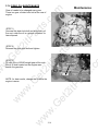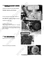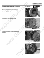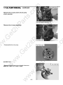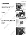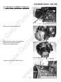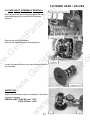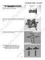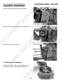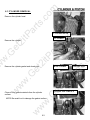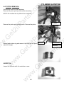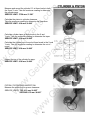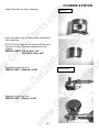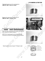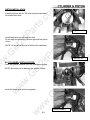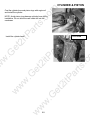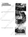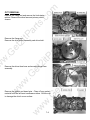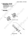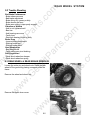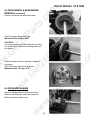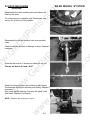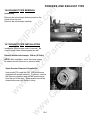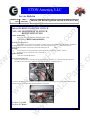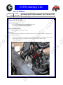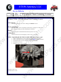
1
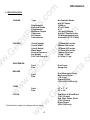
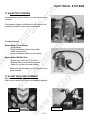
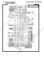
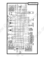
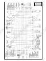
om
rts
.c
om
tP
ar
ts
.c
2i
tP
a
.G
et
ar
ts
.c
.G
et
w
2i
w
ETON America
2i
tP
.G
et
Covers:
w
w
w
150cc Service Manual
w
w
w
YXL-150, CXL-150, RXL-150R
200028
w
w
.G
et
w
ar
ts
.c
2i
tP
rts
.c
om
tP
ar
ts
.c
2i
.G
et
tP
a
2i
.G
et
w
w
w
w
w
om
om
tP
ar
ts
.c
Table of Contents
tP
a
.G
et
.G
et
w
w
w
w
w
.G
et
w
2i
tP
2i
w
w
ar
ts
.c
rts
.c
om
Information
Maintenance
Engine Removal And Installation
Engine Lubrication And Cooling System
Cylinder Head & Valves
Cylinder & Piston
Transmission System
Front Wheel, Suspension And Steering
Rear Wheel System
Fenders And Exhaust Pipe
Electrical System
Trouble Shooting
2i
1.
2.
3.
4.
5.
6.
7.
8.
9.
10.
11.
12.
om
Information
GASOLINE
2i
Gasoline is extremely flammable and is explosive under certain conditions. Do not smoke or allow
sparks or flames in your work area.
CARBON MONOXIDE
BATTERY ELECTROLYTE
tP
a
.G
et
Never run the engine in a closed area. The exhaust contains poisonous carbon monoxide gas that
may cause loss of consciousness and lead to death.
2i
.G
et
HOT PARTS
ar
ts
.c
The battery electrolyte contains sulfuric acid. Protect your eyes, skin, and clothing. If you come into
contact with the electrolyte, flush the area thoroughly with water. If you get the electrolyte in your eyes,
flush with water and contact a doctor immediately.
w
w
USED ENGINE / GEAR OIL
2i
tP
w
The engine and exhaust pipe become very hot and remain hot for one hour after the engine is
run. Wear insulated gloves before handling these parts.
.G
et
Used engine oil and gear oil may cause damage after prolonged exposure to the skin. Keep out of
reach of children.
w
1.2 NOTES
w
All information, illustrations, directions and specifications included in this publication are base on the
latest product information available at the time of approval for printing.
w
ETON America, LLC reserves the right to make changes at any time without notice and without
incurring any obligation whatever.
No part of this publication may be reproduced without written permission.
w
w
rts
.c
om
1.1 Safety
tP
ar
ts
.c
1. INFORMATION
1.1 Safety
1.2 Notes
1.3 Specifications
1.4 Serial number
1.5 Torque valve
1-2
om
Information
tP
ar
ts
.c
Type
2i
Displacement
Bore and Stroke
Compression
Maximum Torque
Carburetor
Air Cleaner
Transmission
2i
tP
a
Overall Length
Overall Width
Overall Height
Wheel base
Ground Clearance
Dry Weight
Fuel Tank Capacity
Front
Rear
Dual Mechanical Drum
Mechanical Drum
(YXL only)
Hydraulic Disc
(CXL & RXL-150R only)
21” x 7” - 8”
22” x 10”
Front
Rear
.G
et
w
TIRES
2i
tP
Dual A-arm
Swing Arm
w
BRAKES
1730mm/68.1 inches
980mm/38.6 inches
1070mm/42.1 inches
1115mm/43.9 inches
140mm/5.5 inches
172kg / 379lbs
6.5 liters/1.7 gal
Front
Rear
.G
et
SUSPENSION
w
w
COLOR
w
* Specifications subject to change without notice.
w
w
w
.G
et
CHASSIS
Air-Cooled 4-Stroke
with Oil Cooler
149.56 cc
57.4x57.8mm
9.7:1
10.6 ps@7500rpm
Kei-Hin / Electric choke
Oil Bathed element type
Automatic (C.T.V. V-belt)
rts
.c
om
ENGINE
ar
ts
.c
1.3 SPECIFICATION
1-3
Red/Black & Silver/Black
(YXL-150 only)
Red, Blue, Green, Silver
(CXL-150 only)
Black/Yellow
(RXL-150R only)
om
Information
1.4 SERIAL NUMBERS
rts
.c
om
tP
ar
ts
.c
The frame serial number is stamped on the front frame just above the oil cooler. The
engine number is stamped on the left side of the crankcase.
w
.G
et
w
w
w
w
Engine Number
w
ar
ts
.c
2i
tP
.G
et
w
2i
w
tP
a
.G
et
2i
Frame Number
1-4
om
Information
2i
28 N-m ( 20.7 ft-lbs)
12 N-m ( 8.9 ft-lbs)
20 N-m ( 14.8 ft-lbs)
8 N-m (5.9 ft-lbs)
2i
FRAME
Handlebar upper holder bolt
Throttle housing cover screw
Steering shaft nut
Steering shaft holder bolt
Wheel rim bolt
Tie rod lock nut
King pin nut
Handlebar lower holder nut
Front wheel bolt
Front axle nut
Front brake arm nut
Rear brake arm nut
Rear axle nut
Rear wheel bolt
Exhaust muffler mounting bolt
Engine hanger bolt
Rear axle holder bolt
Swingarm pivot nut
Rear shock absorber mounting nut
24 N-m ( 17.7 ft-lbs)
4 N-m ( 2.9 ft-lbs)
50 N-m ( 36.9 ft-lbs)
33 N-m ( 24 ft-lbs)
18 N-m ( 13.3 ft-lbs)
35 N-m ( 25.8 ft-lbs)
40 N-m ( 29 ft-lbs)
40 N-m ( 29.5 ft-lbs)
24 N-m ( 17.7 ft-lbs)
60 N-m ( 44 ft-lbs)
4 N-m ( 3.0 ft-lbs)
7 N-m ( 5.2 ft-lbs)
60 N-m ( 44.3 ft-lbs)
24 N-m ( 17.7 ft-lbs)
30 N-m ( 22.1 ft-lbs)
30 N-m ( 22 ft-lbs)
90 N-m ( 65 ft-lbs)
90 N-m ( 65 ft-lbs)
45 N-m ( 33 ft-lbs)
w
w
w
w
.G
et
w
w
.G
et
w
w
tP
a
.G
et
Cylinder head nut
Spark plug
Cylinder head bolt
Alternator bolt
1-5
ar
ts
.c
ENGINE
5 N-m (3.7 ft-lbs)
10 N-m ( 7.4 ft-lbs)
22 N-m ( 16 ft-lbs)
35 N-m ( 26 ft-lbs)
55 N-m ( 41 ft-lbs)
rts
.c
om
5 mm bolt and nut
6 mm bolt and nut
8 mm bolt and nut
10 mm bolt and nut
12 mm bolt and nut
2i
tP
STANDARD
tP
ar
ts
.c
1.5 TORQUE VALUES
2. Maintenance
0.6-0.7 mm / 0.024 – 0.028”
NGK CR7HSA
5-10 mm / 0.2-0.4”
1600±100rpm
15-25 mm / 0.6-1.0”
10-25 mm / 0.4-1.0”
20*7-8 / 22*10-8
2.2± 0.3 psi (0.15 kgf/cm2)
5±10 mm / 0.2±0.4”
.G
et
w
TORQUE VALUES
SPARK PLUG
TIE-ROD LOCK NUT
2i
tP
SPARK PLUG:
Spark plug gap:
Recommended spark plugs:
Throttle lever free play:
Idle speed:
Brake lever free play:
Drive chain slack
Front/rear tire size
Front/rear tire pressure
Toe-in
2i
SPECIFICATION
tP
a
2.1 MAINTENANCE DATA
ar
ts
.c
2i
rts
.c
om
tP
ar
ts
.c
Maintenance data
Maintenance schedule
Fuel tube
Throttle operation
Throttle cable adjustment
Air cleaner
Spark plug
Idle speed
Drive chain
Brake system
Wheels and tires
Steering system
Toe-in
Gear oil
.G
et
2.1
2.2
2.3
2.4
2.5
2.6
2.7
2.8
2.9
2.10
2.11
2.12
2.13
2.14
w
w
12-19 N-m / 9-14 ft-lbs
35-43 N-m / 26-32 ft-lbs
.G
et
ENGINE OIL
Viscosity :
API service classification
SAE 40 (10W-40)
SF or SG
w
GEAR LUBRICATION OIL
Viscosity:
w
w
SAE 90 (80/90 weight gear oil)
w
w
om
Maintenance
2-1
om
Maintenance Schedule
Four Stroke Vehicles
tP
ar
ts
.c
WP-0027
300KM 2000 Miles 3700 Miles 7500 Miles NEW 1 Month 3 Months 6 Months 1 Year C * I I I Change I I R(paper) C I R(sponge) R I Change I R I I I I I I I I I I I I I I I I I I/L I 11 12 Check crankcase for leakage Transmission oil 13 Drive belt/roller 14 Fuel tank switch and lines Throttle valve operation and cable 19 Cam Chain/ignition time 20 Valve clearance 21 Shock absorbers 22 Front/Rear suspension 23 Main/Side stands 25 Crankcase (PCV) Valve Brake mechanism/brake lin‐
ing (pad) 26 Tighten all Bolts/Nuts & Fas‐
teners w
24 w
17 I Change I I I I .G
et
18 Engine bolts and nuts Cylinder head, cylinder, and piston Exhaust system/cleaning carbon w
16 I .G
et
15 I tP
a
.G
et
8 2i
7 2i
6 I I ar
ts
.c
Check transmission for leak‐
age 5 Air cleaner element 2i
tP
10 3 4 w
I I * = Clean or replace the air cleaner element more often when the vehicle is operated on dusty R = Replace C = Clean (replaced if necessary) L = Lubricate # = Maintenance should be performed more often if the vehicle is frequently operated at high w
Code: I = Inspection, clean, and adjust w
roads or in a heavily polluted environment. speed for prolonged time and after the vehicle has accumulated 50,000 miles. w
w
600 Miles 9 2 Every 12000KM 200 Miles I * I Air cleaner C Oil filter (Screen) Engine oil Change I Tire, pressure I Battery I Spark plug I Carburetor (idle speed) I Steering bearing and handles 1 Every 1000KM Every 3000KM Every 6000KM rts
.c
om
Scheduled Maintenance 2.2 MAINTENANCE SCHEDULE
tP
ar
ts
.c
The maintenance intervals in the follow table are based upon average riding conditions. Riding in
unusually dusty areas requires more frequent servicing. E-TON recommends that all maintenance
and inspections be performed ONLY by a qualified and fully trained technician.
(First Week) _________ (30 Operating days) _____ (Once each Year)
X
X
X
X
X
X
R
R
C
X
Initial Service
Regular Service
Yearly Service
2i
X: Inspect and Clean, Adjust, Lubricate or Replace, if necessary
C: Clean
L: Lubricate
R: Replace
2i
tP
w
2.3 FUEL TUBE
w
w
w
w
.G
et
w
Inspect the fuel lines for deterioration,
damage, or leaks, and replace if
necessary.
ETON 150cc models are equipped with
a vacuum fuel valve. Fuel is
transferred into the carburetor when a
vacuum is created from the engine.
Fuel should not flow if engine is not
running or if vacuum is not applied.
ar
ts
.c
X
X
X
R
C
X
X
C
X
X
X,L
rts
.c
om
X
X,L
.G
et
Note -
X
X
tP
a
.G
et
2i
FUEL LINE
THROTTLE OPERATION
AIR CLEANER
SPARK PLUG
CARBURETOR IDLE SPEED
DRIVE CHAIN
BRAKE SHOE WEAR
BRAKE SYSTEM
NUT, BOLT, FASTENER
WH EEL/TIRES
STEERING SYSTEM
SUSPENSION SYSTEM
GEAR OIL
ENGINE OIL
ENGINE OIL FILTER
w
w
om
Maintenance
Vacuum
control line
2-2
om
tP
ar
ts
.c
2.4 THROTTLE OPERATION
rts
.c
om
Inspect for smooth lever operation, full opening, and automatic
full closing in all steering positions.
Inspect for deterioration, damage, cuts and nicks, or kink in
the throttle cable, replace it if necessary.
2i
Check the throttle lever; free play should be no more than
5-10 mm / 0.2-0.4” at the tip of the throttle lever.
2i
2.5 THROTTLE CABLE ADJUSTMENT
Throttle cable adjuster
w
w
w
w
.G
et
w
w
2i
tP
.G
et
Slide the rubber cap of the adjuster off the throttle
housing, loosen the lock nut, and adjust the free
play of the throttle lever by turning the adjuster on
the throttle housing. Inspect the free play of the
throttle lever.
ar
ts
.c
tP
a
.G
et
Disconnect the throttle cable at the upper end. Lubricate the
cable with commercially lubricant to prevent premature wear.
w
w
Maintenance
2-3
tP
ar
ts
.c
(1) Loosen the screws and remove the air cleaner from carburetor.
(2) Disassemble the air cleaner cover and body.
(4) Wash the element in non-flammable or high
flash point solvent squeeze out the solvent thoroughly and allow it to dry.
2i
.G
et
(5) Soak the element in gear oil (SAE 80-90) and
squeeze out the excess.
w
w
w
w
.G
et
w
w
(7) Assemble the air cleaner body and cover and
attach to the carburetor with the screw.
2i
tP
(6) Install the air cleaner element and screen in
the body.
2-4
ar
ts
.c
tP
a
.G
et
2i
rts
.c
om
(3) Clean the air cleaner element and screen. (See Figure below)
w
w
om
2.6 AIR CLEANER MAINTENANCE
Maintenance
om
2.7 SPARK PLUG
(1) Disconnect the spark plug cap and remove the
spark plug.
(2) Visually inspect the spark plug electrodes for
wear or cracks in insulator. Replace if
needed.
(3) The center electrode should have square edges
and the side electrode should have a
constant thickness.
2i
(4) Discard the spark plug if there is apparent wear
or if the insulator is cracked or chipped.
tP
a
.G
et
(5) Measure the gap with a wire-type feeler gauge and
adjust if necessary by carefully bending the
side electrode.
rts
.c
om
tP
ar
ts
.c
The spark plug is located at the front of the engine.
2i
(6) Check the sealing washer and replace with a new
one if damaged.
2.8 IDLE SPEED SETTING
w
.G
et
w
(1) Inspect and adjust the idle speed after all other
engine maintenance has been performed and is within
specifications. The engine must be warm for accurate
idle speed inspection and adjustment.
2i
tP
w
.G
et
(7) With the sealing washer attached thread the spark
plug in by hand to prevent cross threading.
Tighten the spark plug.
TORQUE : 12-19 N-m / 9-14 ft-lbs
(2) Warm up the engine for about ten minutes and
connect a tachometer.
w
w
IDLE SPEED : 1700 ± 100 rpm
w
(3) Turn the throttle stop screw as required to obtain
the specified idle speed.
2-5
ar
ts
.c
SPARK PLUG GAP : 0.6-0.7 mm
Recommended replacement plug: NGK CR7HSA
w
w
Maintenance
tP
ar
ts
.c
Stop the ATV and shift transmission into
neutral. Inspect the chain slack midway
between the sprockets. The standard is
10-25mm (5/8 – 1”).
.G
et
Loosen the axle holder lock nuts then
adjust the drive chain slack by turning the
adjusting nut. Tighten the axle holder lock
nuts.
2i
tP
a
Torque = 90N-m (65 ft-lbs)
.G
et
When the drive chain becomes very dirty, it
should be removed, cleaned, and lubricated with
commercially available lubricant.
2i
tP
Clean the drive chain with kerosene and wipe it
dry.
w
w
Inspect the drive chain for possible wear or
damage.
w
.G
et
Replace the chain if it is worn excessively or
damaged.
Inspect the sprocket teeth; if there is
excessive wear or damage, replace.
w
w
Use a commercial chain lubricant to lubricate the
drive chain; replace and adjust the slack as
described above.
w
ar
ts
.c
2i
rts
.c
om
If needed, remove the chain protective
cover and adjust the chain slack.
w
w
om
2.9 DRIVE CHAIN ADJUSTMENT
Maintenance
2-6
om
tP
ar
ts
.c
2.10 BRAKE SYSTEM ADJUSTMENT
rts
.c
om
Inspect the front brake lever and cable for excessive play
or damage.
Replace or repair if necessary.
Measure the free play of the brake lever at the end of the
lever. The standard is 15-25 mm / 0.59-0.98”.
2i
Adjust the free play of the front brake lever by turning the
adjuster on the brake lever assembly.
2i
.G
et
Adjust the free play of the rear brake lever by turning the
adjuster on the rear axle.
Front Brake
w
.G
et
w
w
Loosen the front brake cable and inspect the brake lining
thickness.
Service Limit: 2.0mm (0.08”)
If either lining is worn beyond the service limit, replace both
brakes shoes.
2i
tP
BRAKE SHOE WEAR
Rear Brake
w
w
w
Replace the brake shoes if there is uneven wear or if the
lining is worn beyond the service limit.
2-7
ar
ts
.c
The standard is 10-20 mm / 0.39-0.78”.
tP
a
.G
et
Inspect the rear brake lever and cable for excessive play or
damage.
Replace or repair if necessary.
Measure the free play of the brake lever at the end of the
lever.
w
w
Maintenance
om
tP
ar
ts
.c
2.11 WHEELS AND TIRES
Maintenance
.G
et
2.12 STEERING SYSTEM
2i
tP
.G
et
w
2i
w
tP
a
Check the free play of the steering shaft with the
front wheels turned straight ahead. If there is
excessive play, inspect the tie-rod, kingpin bushing,
and ball joint.
w
Steering Shaft Holder Bushing
.G
et
w
Remove the front fender.
Remove the steering shaft holder and check the
steering shaft bushing for wears or damage.
If the bushing is worn or damaged, replace.
Grease the steering shaft bushing and install the
parts in the reverse order of removal.
w
w
w
Torque steering shaft holder bolt: 33 N-m (24 ft-lbs)
w
ar
ts
.c
2i
Check the tire pressure at cold tire conditions.
The standard tire pressure is 2.2±0.3 psi (0.15
kgf/cm2).
rts
.c
om
Inspect the tire surfaces for cuts or sharp
objects.
2-8
om
2.13 TOE-IN
Maintenance
tP
ar
ts
.c
Park the vehicle on level ground with the front
wheels facing straight ahead.
Mark the centers of the tires to indicate the axle
center height.
tP
a
.G
et
2i
Carefully moving the vehicle backward, let the
wheels turn 180° so the marks on the tires are
aligned with the axle center height.
rts
.c
om
Measure the distance between the marks.
w
.G
et
w
If the toe-in is out of standard, adjust it by
changing the length of the tie-rods equally by
turning the tie-rod while holding the ball joint.
Tighten the lock nuts.
w
w
w
Torque: 35-43 N-m / 26-32 ft-lbs
ar
ts
.c
2i
tP
w
.G
et
w
Toe-in: 5±10mm / 0.2±0.4”
2i
w
Measure the distance between the marks.
Calculate the difference in the front and rear
measurements.
2.14 GEAR OIL MAINTENANCE
om
Maintenance
tP
ar
ts
.c
Gear oil needs to be changed every year.
There is a gear oil drain hole bolt at the rear of
engine.
tP
a
.G
et
(STEP 2)
Reinsert the drain hole bolt and tighten.
Drain bolt
Drain Bolt
.G
et
w
2i
w
(STEP 3)
Fill with 26oz of 80/90 weight gear oil through
the oil fill hole located on the engine case
beside the gear box.
w
w
w
w
.G
et
w
w
2i
tP
NOTE: for best results, change the oil while the
engine is warm.
ar
ts
.c
2i
rts
.c
om
(STEP 1)
Unscrew this drain hole bolt and let the dirty oil
flow out; catch the oil in a proper container for
later disposal.
Oil Fill Plug
2-10
om
ENGINE REMOVAL AND REPLACEMENT
3.1 ENGINE REMOVAL AND INSTALLATION
tP
ar
ts
.c
ENGINE SHOULD ONLY BE REMOVED IN THE CONDITIONS OF NECESSARY REPAIRS OR
ADJUSTMENT TO THE TRANSMISSION AND COMBUSTION SYSTEM!
3.2 ENGINE REMOVAL
tP
a
Remove the drive chain cover.
Remove the drive chain retaining clip and master
link, and remove the drive chain.
2i
.G
et
Remove the engine hanger bolts under the engine.
w
3.2 ENGINE REPLACEMENT
.G
et
w
Engine installation is essentially the reverse order
of removal.
The torque of the engine hanger bolt is 30 N-m / 22
ft-lbs.
w
w
w
Route the wires and cable properly in reverse
order of removal.
2i
tP
w
Remove the engine and air cleaner together
3-1
ar
ts
.c
2i
.G
et
Disconnect the carburetor auto-choke (if
equipped), starter motor, generator, the neutral
safety switch, CDI box, and the ignition coil wire.
w
w
rts
.c
om
Remove the seat, front and rear fender.
(See Chapter 10 )
Remove the footrest.
Remove the spark plug cap from the spark plug.
Remove the exhaust muffler.
Disconnect the carburetor cable by unscrewing
the two screws on top of the carburetor.
4. Lubrication
tP
ar
ts
.c
4.1 Service Information
4.2 Trouble Shooting
4.3 Engine Oil Level
4.4 Engine Oil & Filter Change
4.5 Oil Pump Removal / Installation
rts
.c
om
4.1 SERVICE INFORMATION
tP
a
SPECIFICATIONS
ITEM
Cylinder compression
Cam lobe height
STANDARD
12±0.5 kg/cm2
29.795mm / 1.180”
IN
EX 29.560mm / 1.16”
10.000-10.018mm / 0.394”
9.972-9.987mm / 0.393 “
-------32.3mm / 1.27”
IN
EX 35.0mm / 1.38”
4.975-4.990mm / 0.196”
IN
EX 4.955-4.970mm / 0.195”
IN/EX 5.000-5.012mm / 0.197”
0.010-0.037mm
IN
EX 0.030-0.057mm
1.0mm
IN
EX 1.0mm
w
Valve guide I.D.
Stem-to-guide clearance
w
Valve seat width
w
TORQUE VALUES
8 - 12 N-m (6-9 ft-lbs)
20 - 24 N-m (15-18 ft-lbs)
9 - 12 N-m (7-9 ft-lbs)
20-30 N-m (15-22 ft-lbs)
w
w
w
Cylinder head bolts
Camshaft holder flange nuts
Tappet adjusting nut
Oil Drain Bolt
.G
et
Valve stem O.D.
2i
tP
.G
et
2i
Rocker arm I.D.
Rocker arm shaft O.D.
Cylinder head warp
Valve spring free length
SERVICE LIMIT
-------29.395mm / 1.157”
29.160mm / 1.148”
10.10mm / 0.398”
9.91mm / 0.390”
0.05mm
31.2mm / 1.23”
34.1mm / 1.34”
4.90mm / 0.193”
4.90mm / 0.193”
5.30mm / 0.209”
0.08mm
0.10mm
1.80mm
1.80mm
ar
ts
.c
.G
et
2i
GENERAL
1. This section describes cylinder head, valves, camshaft, and other parts maintenance.
2. The engine must be removed from the frame to service the cylinder head.
3. Camshaft lubrication oil is fed to the cylinder head through an oil hole in the engine case.
4. Before installing the cylinder head, be sure the hole is not clogged and the gasket, O-ring,
and dowel pins are in place
w
w
om
LUBRICATION
4-1
om
4.2 TROUBLE SHOOTING
tP
ar
ts
.c
Engine top-end problems often affect engine performance. These problems can be diagnosed by a
compression test, or by tracing engine noise to the top end with a sounding rod or stethoscope.
2i
Cylinder head
-Leaking or damaged head gasket.
-Warped or cracked cylinder head.
-Faulty cylinder or piston.
2i
tP
a
.G
et
Excessive noise
-Incorrect valve adjustment.
-Sticking valve or broken valve spring.
-Worn or damaged rocker arm or camshaft.
-Worn or damaged cam chain.
-Worn or damaged cam chain tensioner.
-Worn cam sprocket teeth.
.G
et
Excessive smoke
-Damaged valve stem seal.
-Faulty cylinder or piston rings.
4.3 ENGINE OIL LEVEL
w
w
2i
tP
Place the engine on the level plane.
Check the oil level with the oil level
dipstick, but do not screw it in when
making this check.
w
w
.G
et
4.3.1 TROUBLESHOOTING
Oil level too low-high oil consumption
-Typical oil consumption.
-External oil leaks.
-Oil not changed often enough.
-Worn piston rings.
w
Oil contamination
-Worn piston rings.
-Oil or filter not changed often enough.
w
ar
ts
.c
rts
.c
om
Low compression (Valve)
-Incorrect valve adjustment.
-Worn or damaged valve seats.
-Burned or bent valve.
-Incorrect valve timing.
-Weak valve spring.
w
w
LUBRICATION
4-2
Engine
Oil
Dipstick
rts
.c
om
tP
ar
ts
.c
Add the recommended oil up to the upper
level if the oil level is below or near lower level
line on the gauge.
2i
4.4 ENGINE OIL & FILTER CHANGE
LOWER LEVEL
.G
et
Remove the oil drain plug.
NOTE: Drain the oil while the engine is warm to
tP
a
ensure complete draining.
.G
et
2i
Check the O-ring for damage or wear.
Install a new oil filter screen and spring; then,
install the plug.
ar
ts
.c
Remove the oil drain plug, spring, and oil filter
screen.
w
w
2i
tP
Oil drain plug
.G
et
w
OIL DRAIN PLUG
w
w
w
w
w
om
4.3 ENGINE OIL LEVEL (continued)
LUBRICATION
O-RING
4-3
om
4.4 ENGINE OIL & FILTER CHANGE
(continued)
tP
ar
ts
.c
Install the oil drain bolt with sealing washer.
rts
.c
om
TORQUE: 20-30 N-m (15-22 ft-lbs)
2i
OIL CAPACITY: 0.8 liter / 0.2 gal at draining.
.G
et
Install the oil drain plug.
tP
a
Install the oil level gauge.
Start the engine and let it idle for 2 - 3 minutes.
Oil drain plug
.G
et
w
2i
w
Stop the engine and check that the oil level is
at the upper line on the gauge. Make sure there
are no oil leaks.
OIL DRAIN PLUG
2i
tP
4.5 OIL PUMP REMOVAL
w
.G
et
w
w
Remove the fan cover assembly.
w
w
w
Remove the cooling fan assembly.
ar
ts
.c
Fill the crankcase with the SAE 10w40 oil.
4-21
om
tP
ar
ts
.c
FLYWHEEL
tP
a
2i
w
w
w
w
Remove the flange bolts and oil separator.
.G
et
w
w
2i
tP
.G
et
Remove the starting clutch outer and gear
assembly.
ar
ts
.c
2i
.G
et
w
w
rts
.c
om
Remove the flywheel and the AC Generator
assembly. Flywheel pullers are available
from the ETON Parts Department.
4-5
om
tP
a
2i
2i
tP
.G
et
w
w
w
.G
et
INSPECTION
Measure the oil pump rotor-to-body clearance.
w
w
w
SERVICE LIMIT: 0.12 mm / 0.005”
ar
ts
.c
rts
.c
om
tP
ar
ts
.c
2i
.G
et
w
w
Disassemble the oil pump.
4-6
om
tP
ar
ts
.c
w
.G
et
w
w
Install the outer rotor, inner rotor and oil pump shaft
onto the body.
NOTE: Pour a drop of clean engine oil inside
the oil pump.
2i
tP
.G
et
4.5 OIL PUMP ASSEMBLY / INSTALLATION
w
w
w
Install the oil pump assembly.
4-7
ar
ts
.c
OIL PUMP INNER ROTOR
2i
w
w
OIL PUMP OUTER ROTOR
tP
a
.G
et
2i
Remove the oil pump shaft and measure the pump
end clearance.
SERVICE LIMIT: 0.2 mm / 0.008”
rts
.c
om
Install the oil pump shaft and measure the pump rotor
tip clearance.
SERVICE LIMIT: 0.12 mm / 0.005”
om
LUBRICATION
4.5 OIL PUMP ASSEMBLY / INSTALLATION
(continued)
w
w
w
.G
et
w
w
Install the starting clutch outer and gear assembly.
2i
tP
.G
et
w
2i
w
tP
a
.G
et
Install the oil separator.
w
Install the new gasket, dowel pins, and right crankcase
cover.
4-8
ar
ts
.c
2i
rts
.c
om
tP
ar
ts
.c
Install the oil pump driven sprocket and oil pump
chain.
om
LUBRICATION
4.5 OIL PUMP ASSEMBLY / INSTALLATION
(continued)
FLYWHEEL
.G
et
w
2i
w
tP
a
.G
et
Install the cooling fan.
w
w
w
w
.G
et
w
w
2i
tP
Install fan housing cover.
ar
ts
.c
2i
rts
.c
om
tP
ar
ts
.c
Install the AC Generator and then the outer flywheel.
4-9
om
LUBRICATION
4.6 ENGINE OIL
tP
ar
ts
.c
This section describes inspection and replacement of the engine oil, oil filter screen, and
assembly of the oil pump.
Fill the oil pump with clean oil when reassembling the pump.
rts
.c
om
SPECIFICATION
0.8-1.0 liter / 0.2-0.3 gal
Viscosity: SAE 20w-40
2i
ENGINE OIL CAPACITY
API service classification: SF or SG
w
w
w
w
.G
et
w
w
ar
ts
.c
2i
tP
.G
et
w
2i
w
tP
a
.G
et
When the average temperature in your riding area is within the indicated range,
you should use the other engine oil viscosity that's shown in the chart.
4-10
om
CYLINDER HEAD / VALVES
5. CYLINDER HEAD / VALVES
tP
ar
ts
.c
5.1 SERVICE INFORMATION
5.2 TROUBLESHOOTING
5.3 CAMSHAFT ASSEMBLY REMOVAL
5.4 CYLINDER HEAD REMOVAL
5.5 CYLINDER HEAD INSTALLATION
GENERAL
ITEM
STANDARD
I.D.
TAPER
OUT OF ROUND
WARPAGE ACROSS TOP
Piston
PISTON O.D.
Piston pin
PISTON PIN BORE
Piston rings PISTON PIN O.D.
PISTON-TO-PIN CLEARANCE
PISTON-TO-PIN CLEARANCE
PISTON RING-TO-RING
GROOVE CLEARANCE
PISTON RING END GAP
CYLINDER-TO-PISTON CLEARANCE
CONNECTING ROD SMALL END I.D.
SERVICE LIMIT
57.400 - 57.410mm / ~2.260”
---------------------------------57.3075 - 57.3095mm / ~2.256”
15.002 - 15.008mm / ~0.0510”
14.994 – 15.000mm / ~0.590”
0.002 – 0.014mm/7.8x10-5-0.0006”
0.015 – 0.050mm/0.0006-0.002”
0.015 – 0.050mm/0.0006-0.002”
0.10 – 0.25mm/0.004-0.01”
0.2 –0.7mm/0.008-0.03”
0.0005 – 0.1025mm/2.0x10-6-0.004”
15.010 – 15.028mm / ~0.591”
.G
et
w
TORQUE VALUES
Cylinder head bolts
Camshaft holder flange nuts
Tapper adjusting nut
57.50mm / 2.263”
0.10mm / 0.004”
0.10mm / 0.004”
0.10mm / 0.004”
56.5mm / 2.22”
15.04mm / 0.592”
14.960mm / 0.589””
0.02mm/0.0008”
0.12mm/0.005”
0.12mm0.005”
0.5mm/0.02”
----------0.1mm/0.004”
15.06mm / 0.593”
2i
tP
TOP
SECOND
TOP/SEC
OIL
w
w
.G
et
2i
Cylinder
tP
a
SPECIFICATIONS
ar
ts
.c
.G
et
2i
This section describes the maintenance of cylinder head, valves, camshaft, and the other parts.
The engine must be removed from the frame to service the cylinder head.
Camshaft lubrication oil is fed to the cylinder head through an oil hole in the engine case. Before
installing the cylinder head, be sure the hole is not clogged and the gasket, O-ring, and dowel
pins are in place.
w
w
w
8-12 N-m / 6-9ft-lbs
20-24 N-m / 15-18 ft-lbs
9-12 N-m / 7-9 ft-lbs
w
w
rts
.c
om
5.1 SERVICE INFORMATION
5-1
tP
ar
ts
.c
5.2 TROUBLE SHOOTING
2i
Low compression Valve
-Incorrect valve adjustment.
-Worn or damaged valve seats.
-Burned or bent valve.
-Incorrect valve timing.
-Weak valve spring.
tP
a
.G
et
Cylinder head
-Leaking or damaged head gasket.
-Warped or cracked cylinder head.
-Faulty cylinder or piston.
w
w
w
w
.G
et
w
w
Excessive smoke
-Damaged valve stem seal.
-Faulty cylinder or piston rings
2i
tP
.G
et
2i
Excessive noise
-Incorrect valve adjustment.
-Sticking valve or broken valve spring.
-Worn or damaged rocker arm or camshaft.
-Worn or damaged cam chain.
-Worn or damaged cam chain tensioner.
-Worn cam sprocket teeth.
5-2
ar
ts
.c
rts
.c
om
Engine top-end problems often affect engine performance. These problems can be diagnosed by a
compression test, or by tracing engine noise to the top end with a sounding rod or stethoscope.
w
w
om
CYLINDER HEAD / VALVES
om
CYLINDER HEAD / VALVES
5.3 CAM SHAFT ASSEMBLY REMOVAL
tP
a
2i
tP
w
.G
et
2i
Remove the air cleaner and carburetor.
Remove the inlet pipe assembly.
Remove the engine shroud.
w
ENGINE SHROUD
.G
et
Loosen the cam chain adjuster screw.
w
w
w
w
w
w
.G
et
2i
Remove the cylinder head cover.
5-3
ar
ts
.c
rts
.c
om
tP
ar
ts
.c
Remove the rubber gas waste recovery tube.
om
CYLINDER HEAD / VALVES
5.3 CAM SHAFT ASSEMBLY REMOVAL
(continued)
2i
2i
tP
.G
et
w
w
.G
et
Loosen the camshaft gear from cam chain and remove
the camshaft.
w
INSPECTION
w
w
w
Inspect the cam lobes surface and height of cam lobes
for wear or damage.
SERVICE LIMIT: IN 29.395 mm / 1.157”
EX 29.160 mm / 1.148”
ar
ts
.c
tP
a
.G
et
2i
Remove the nuts and washers.
Remove the camshaft holder and dowel pins.
w
w
rts
.c
om
tP
ar
ts
.c
Remove the screw and O-ring and tighten the cam
chain-adjusting bolt by turning in the clockwise
direction.
om
CYLINDER HEAD / VALVES
5.3 CAM SHAFT ASSEMBLY REMOVAL
(continued)
w
w
w
2i
tP
.G
et
Measure the I.D. of each rocker arm.
SERVICE LIMIT: 10.10 mm / 0.3976”
Measure the O.D. of each rocker arm shaft.
SERVICE LIMIT: 9.91 mm / 0.390”
5-5
ar
ts
.c
2i
w
w
.G
et
Inspect the camshaft holder, rocker arms, and rocker
arm shafts for wear or damage.
w
w
w
tP
a
.G
et
2i
Screw a 5mm bolt into the rocker arm shaft threaded
end. Pull on the bolt to remove the shafts and rocker
arms.
rts
.c
om
tP
ar
ts
.c
Inspect the camshaft and bearings for wear or damage and replace them if necessary.
om
.G
et
2i
tP
2i
w
w
.G
et
Remove the cam chain guide.
w
CYLINDER HEAD DISASSEMBLY
w
w
w
Remove the valve cotters, spring retainers, and
valve springs with a valve spring compressor.
ar
ts
.c
tP
a
.G
et
2i
Remove the cylinder head gasket and dowel pins.
rts
.c
om
tP
ar
ts
.c
Remove the flange bolts and cylinder head.
w
w
CYLINDER HEAD / VALVES
5.4 CYLINDER HEAD REMOVAL
(continued)
w
ar
ts
.c
Measure the free length of the inner and outer
valve springs.
SERVICE LIMITS: Inner 31.2 mm / 1.23”
Outer 34.1 mm / 1.34”
OUTER VALVE SPRING
2i
tP
.G
et
w
2i
w
tP
a
.G
et
Measure the cylinder head diagonally for warping
with a straight edge and feeler gauge.
SERVICE LIMIT: 0.05 mm / 0.002”
rts
.c
om
2i
tP
ar
ts
.c
INSPECTION
Clean off all carbon deposits from the combustion and check the spark plug hole and
valve area for cracks.
om
CYLINDER HEAD / VALVES
5.4 CYLINDER HEAD REMOVAL
w
w
w
Inspect each valve for turning, burning,
scratches, or abnormal stem wear. Check
the valve movement in the guide.
.G
et
w
w
INNER VALVE SPRING
5-7
Measure and record each valve stem O.D.
SERVICE LIMITS: 4.90 mm / 0.19”
tP
ar
ts
.c
Measure and record the valve guide I.D.
SERVICE LIMITS: IN / EX 5.30 mm / 0.209”
rts
.c
om
Calculate the stem-to-guide clearance.
SERVICE LIMITS: IN 0.08 mm / 0.003”
EX 0.10 mm / 0.004”
NOTE: If the stem-to-guide clearance exceeds the service
limits, determine if a new guide with standard dimensions
would bring the clearance within tolerance.
2i
w
.G
et
w
w
NOTE: To prevent loss of tension, do not
compress the valve springs more than
necessary.
2i
tP
.G
et
Lubricate each valve stem with oil.
Insert the valves into the guides.
Install the valve springs, retainers, and the cotters.
INSTALLATION
w
w
w
Install the new gasket and dowel pins.
5-8
ar
ts
.c
5.5 CYLINDER HEAD ASSEMBLY
tP
a
.G
et
2i
If so, replace guides as necessary and ream to fit. If the valve guide is replaced, the valve seat
must be refaced.
w
w
om
CYLINDER HEAD / VALVES
w
w
.G
et
w
ar
ts
.c
2i
tP
rts
.c
om
tP
ar
ts
.c
2i
.G
et
tP
a
2i
.G
et
w
w
w
w
w
om
om
CYLINDER HEAD / VALVES
2i
.G
et
5.6 CAMSHAFT ASSEMBLY INSTALLATION
w
2i
tP
.G
et
w
w
Install the rocker arms and rocker arm shafts into the
camshaft holder.
w
w
w
Align the "T" mark (as shown in picture) on the flywheel
with the index mark on the alternator cover by turning the
flywheel counter-clockwise.
5-9
ar
ts
.c
tP
a
.G
et
2i
Install the cylinder head.
w
w
rts
.c
om
tP
ar
ts
.c
Install the cam chain guide.
om
CYLINDER HEAD / VALVES
2i
w
2i
tP
.G
et
w
w
.G
et
Adjust the clearance between the rocker arm and
valve stem by applying a feeler gauge.
STANDARD VALVE: 0.08 – 0.12 mm / 0.003-0.005”
w
w
w
Loosen the cam chain-adjusting bolt by turning in a
counterclockwise direction. Install the O-ring and screw.
5-10
ar
ts
.c
tP
a
rts
.c
om
tP
ar
ts
.c
.G
et
2i
Install the dowel pins and camshaft holder. Tighten
the washers and nuts.
TORQUE: 20 N-m (15 ft-lbs)
w
w
I MARK
Position the camshaft gear with cam chain so that its
"I" mark aligns with the cylinder head surface and the
circle hole towards the front.
om
CYLINDER HEAD / VALVES
w
w
w
w
.G
et
w
w
ar
ts
.c
2i
tP
.G
et
w
2i
w
tP
a
.G
et
2i
rts
.c
om
tP
ar
ts
.c
Install the cylinder head cover.
5-11
6. CYLINDER AND PISTON
tP
ar
ts
.c
6.1 SERVICE INFORMATION
6.2 TROUBLESHOOTING
6.3 CYLINDER REMOVAL
6.4 PISTON REMOVAL
6.5 CYLINDER INSTALLATION
GENERAL
rts
.c
om
6.1 SERVICE INFORMATION
.G
et
SPECIFICATIONS
STANDARD (mm / in)
ITEM
I.D.
Taper
Out of round
Warp across top
Piston
Piston O.D.
Piston pin
Piston pin bore
Piston rings
Piston pin O.D.
Piston-to-pin clearance
Piston ring
TOP
SECOND
Groove Clearance
TOP/SEC
Piston ring end gap
OIL
Cylinder-to-piston clearance
Connecting rod small end I.D.
57.400 - 57.410 / 2.26”
---------------------------------57.3075 - 57.3095 / ~2.26”
15.002 - 15.008 / ~0.59”
tP
a
Cylinder
.G
et
2i
14.994 - 15.000 / ~0.58”
0.002 - 0.014 / ~7.2x10⁻⁵”
0.015 - 0.050 / ~0.0006”
0.015 - 0.050 / ~0.0006”
0.10 - 0.25 / ~0.004”
0.2 -0.7 / ~0.008”
0.0005 - 0.1025 / ~2x10⁻⁵”
15.010 - 15.028 / ~0.56”
8-12 N-m / 6-9 ft-lbs
20-24 N-m / 15-18 ft-lbs
9-12 N-m / 7-9 ft-lbs
w
w
w
w
.G
et
w
w
Cylinder head bolts
Camshaft holder flange nuts
Tappet adjusting nut
57.50 / 2.26”
0.10 / 0.004”
0.10 / 0.004”
0.10 / 0.004
56.500 / 2.22”
15.04 / 0.59”
14.960 / 0.58”
0.02 / 0.0008”
0.12 / 0.005”
0.12 / 0.005”
0.5 / 0.02”
-----------0.1 / 0.004”
15.06 / 0.59”
2i
tP
TORQUE VALUES
SERVICE LIMIT (mm / in)
ar
ts
.c
2i
Camshaft lubrication oil is fed to the cylinder head through an oil hole in the cylinder head and
engine case. Before installing the cylinder head, be sure the hole is not clogged and the gasket, Oring and dowel pins are in place.
w
w
om
CYLINDER & PISTON
6-1
om
CYLINDER & PISTON
6.2 TROUBLESHOOTING
tP
ar
ts
.c
Low or unstable compression
-Worn cylinder or piston rings.
2i
Knocking or abnormal noise
-Worn piston and cylinder.
-Excessive carbon build-up.
w
w
w
w
.G
et
w
w
2i
tP
.G
et
w
2i
w
tP
a
.G
et
Excessive smoke
-Worn cylinder, piston, or piston rings.
-Improper installation of piston rings.
-Scored or scratched piston or cylinder wall.
-Damaged valve stem seal.
ar
ts
.c
rts
.c
om
Overheating
-Excessive carbon build-up on piston or combustion chamber wall.
6-2
rts
.c
om
tP
ar
ts
.c
Remove the cylinder head.
CYLINDER HEAD
BASE GASKET
.G
et
w
Clean off any gasket materials from the cylinder
surface.
w
w
w
NOTE: Be careful not to damage the gasket surface
6-3
DOWEL PINS
2i
tP
2i
w
w
.G
et
Remove the cylinder gasket and dowel pins.
ar
ts
.c
CYLINDER
tP
a
.G
et
2i
Remove the cylinder.
w
w
om
6.3 CYLINDER REMOVAL
CRANKCASE SURFACE
tP
ar
ts
.c
Stuff a shop towel into the crankcase.
Remove the piston pin clip with needle nose pliers.
rts
.c
om
NOTE: Do not allow the clip fall into the crankcase.
C-CLIPS
PISTON
w
INSPECTION
w
w
w
Inspect the cylinder walls for scratches or wear.
6-4
PISTON PIN
2i
tP
PISTON
.G
et
w
w
.G
et
2i
Spread each piston ring and remove it by lifting up at a point
opposite the gap.
ar
ts
.c
tP
a
.G
et
2i
Remove the piston pin from the piston. Remove the piston.
w
w
om
6.4 PISTON REMOVAL
om
tP
ar
ts
.c
Measure and record the cylinder I.D. at three levels in both
the X and Y axis. Take the maximum reading to determine
the cylinder wear.
SERVICE LIMIT: 57.50 mm / 2.264”
rts
.c
om
Calculate the piston-to-cylinder clearance.
Take the maximum reading to determine the clearance.
SERVICE LIMIT: 0.10 mm / 0.004”
2i
Calculate cylinder taper at three levels in the X and
Y-axis. Take the maximum reading to determine the taper.
SERVICE LIMIT: 0.10 mm / 0.004”
w
w
w
w
.G
et
PISTON / PISTON RING INSPECTION
Measure the piston ring-to-groove clearance.
SERVICE LIMITS: TOP 0.12 mm / 0.005”
SECOND 0.12 mm / 0.005”
6-5
ar
ts
.c
2i
tP
w
w
.G
et
w
2i
Inspect the top of the cylinder for warp.
SERVICE LIMIT: 0.10 mm / 0.004”
tP
a
w
.G
et
Calculate the cylinder out-of-round at three levels in the X and
Y-axis. Take the maximum reading to determine the out-of round.
SERVICE LIMIT: 0.10 mm / 0.004”
CYLINDER & PISTON
w
w
w
w
.G
et
Measure the piston pin bore.
SERVICE LIMIT: 15.04 mm / 0.592”
6-6
ar
ts
.c
PISTON PIN
2i
tP
w
w
.G
et
2i
Measure the piston pin O.D.
SERVICE LIMIT: 14.960 mm / 0.589”
tP
a
.G
et
2i
NOTE: Push the rings into the cylinder with the top of
the piston to be sure they are squarely set in the
cylinder.
SERVICE LIMITS: TOP 0.5 mm / 0.02”
SECOND 0.5 mm / 0.02”
rts
.c
om
tP
ar
ts
.c
PISTON
Insert each piston ring into the cylinder and measure
the ring end gap.
w
w
om
Inspect the piston for wear or damage.
CONNECTING ROD
tP
a
.G
et
2i
Measure the connecting rod small end I.D.
SERVICE LIMIT: 15.06 mm / 0.59”
2i
Clean the piston ring grooves thoroughly and install the
piston ring with the marks facing up.
2i
tP
.G
et
w
w
.G
et
NOTE: Don't interchange the top and second rings.
Avoid piston and piston ring damage during installation.
w
w
w
w
Space the piston ring end gaps 120 degrees apart.
6-7
ar
ts
.c
6.5 PISTON & PISTON RING INSTALLATION
w
w
rts
.c
om
tP
ar
ts
.c
Calculate the piston-to-piston pin clearance.
SERVICE LIMIT: 0.02 mm / 0.0008”
om
CYLINDER & PISTON
om
PISTON INSTALLATION
tP
a
2i
6.6 CYLINDER INSTALLATION
.G
et
Clean any gasket material from the crankcase surface.
PISTON PIN
2i
tP
.G
et
w
w
NOTE: Be careful not to damage the gasket surface.
Install the dowel pins and a new gasket.
w
w
w
w
w
w
.G
et
NOTE: Do not allow the clip to fall into the crankcase.
“IN” MARK
ar
ts
.c
2i
Install the piston pin with new pin clips.
Do not align the piston pin clip end gap with the piston
cutout.
rts
.c
om
tP
ar
ts
.c
Install the piston with its "IN" mark pointing up toward
the intake valve side.
6-8
BASE GASKET
om
CYLINDER & PISTON
Coat the cylinder bore and piston rings with engine oil
and install the cylinder.
rts
.c
om
tP
ar
ts
.c
NOTE: Avoid piston rings damage cylinder bore during
installation. Do not allow the cam chain fall into the
crankcase.
.G
et
w
w
w
w
.G
et
w
2i
tP
2i
w
w
w
6-9
ar
ts
.c
CYLINDER
tP
a
.G
et
2i
Install the cylinder head.
7. TRANSMISSION & KICK STARTER
rts
.c
om
tP
ar
ts
.c
7.1 SERVICE INFORMATION
7.2 TROUBLE SHOOTING
7.3 CVT DISASSEMBLY
7.4 KICK STARTER DISASSEMBLY
7.5 KICK STARTER ASSEMBLY
7.6 CVT ASSEMBLY
7.7 TRANSMISSION SYSTEM
2i
7.1 SERVICE INFORMATION
If the drain tube assembly fills with water, the tube should be drained.
.G
et
If replacing transmission parts for YUKON/YUKON II, refer to the bulletin at the end of this manual first!
STANDARD
19.8 - 20.2mm / ~0.780”
17.9 - 18.1mm / ~0.705”
27.98 - 28.0mm / ~1.101”
24.06 - 24.09mm / ~0.945”
23.96 - 23.98mm / ~0.944”
124.8 - 125.2mm / ~4.90”
-----------------168.4 - 169.4mm / ~6.650”
w
.G
et
Driven belt width
Weight roller O.D.
Movable drive face I.D.
Drive face collar I.D.
Drive face boss O.D.
Clutch outer I.D
Clutch weight lining thickness
Driven face spring length
2i
ITEM
55 N-m / 41 ft-lbs
55 N-m / 41 ft-lbs
w
w
w
w
Clutch outer nut
Drive face nut
SERVICE LIMIT
19.0mm / 0.75”
17.40mm / 0.685”
28.03mm / 1.104”
24.098mm / 0.9487”
23.92mm / 0.942”
125.5mm / 4.941”
1.5mm / 0.059”
164.0mm / 6.46”
.G
et
w
TORQUE VALUES
7-1
ar
ts
.c
SPECIFICATIONS
2i
tP
tP
a
Click here to see the service bulletin.
w
w
om
TRANSMISSION & KICK STARTER
om
tP
ar
ts
.c
7.2 TROUBLE SHOOTING
w
w
w
w
2i
tP
.G
et
w
w
.G
et
w
2i
w
tP
a
.G
et
2i
Low engine power
-Worn driven belt.
-Worn weight roller.
-Dirty drive face.
7-2
ar
ts
.c
rts
.c
om
Engine starts but won’t run
-Worn driven belt.
-Worn clutch lining.
-Damaged driven face spring.
tP
ar
ts
.c
LH CRANKCASE COVER REMOVAL
2i
w
2i
tP
.G
et
w
w
.G
et
Remove the gas waste recovery unit.
w
w
w
Remove the 8 bolts and the LH crankcase cover.
7-3
ar
ts
.c
tP
a
.G
et
2i
Loosen the band screw and remove the CVT outlet
duct.
rts
.c
om
Loosen the band screw and remove the CVT inlet
duct.
w
w
om
7.3 CVT DISASSEMBLY
om
CVT REMOVAL
2i
w
.G
et
w
w
2i
tP
.G
et
Remove the driven face boss and movable driven face
assembly.
w
w
Remove the gasket and dowel pins. Clean off any gasket
material from the left hand crankcase surface. Be sure not
to damage the clutch cover surface.
w
ar
ts
.c
tP
a
.G
et
2i
Remove the flange nut.
Remove the drive pulley assembly and driven belt.
w
w
rts
.c
om
tP
ar
ts
.c
Remove the flange nut and remove the kick-starter
ratchet. Remove the drive face and primary clutch
sheave.
7-4
om
.G
et
2i
tP
.G
et
w
w
Inspect the weight rollers for wear or damage and
replace them if necessary.
Measure the O.D. of weight rollers.
SERVICE LIMIT: 17.40 mm / 0.69”
w
w
w
7-5
ar
ts
.c
DRIVEN PLATE ASSEMBLY
2i
INSPECTION
Inspect the drive belt for wear, tearing, or other damage.
Measure the width of drive belt.
SERVICE LIMIT: 19.0 mm / 0.75”
w
w
w
tP
a
.G
et
2i
Loosen the special nut and remove the driven plate
assembly and driven face spring.
rts
.c
om
tP
ar
ts
.c
Remove the ramp plate and weight roller set.
om
w
w
w
w
.G
et
Inspect the clutch weight set for wear or damage.
Measure the thickness of the clutch weight lining.
SERVICE LIMIT: 1.5mm / 0.06”
2i
tP
w
w
.G
et
2i
Inspect the clutch outer for wear or damage.
Measure the I.D. of clutch outer.
SERVICE LIMIT: 125.5 mm / 4.94”
7-6
ar
ts
.c
tP
a
.G
et
2i
Inspect the drive face boss for wear or damage.
Measure the O.D. of the drive face boss.
SERVICE LIMIT: 23.92 mm / 0.94”
w
w
rts
.c
om
tP
ar
ts
.c
Measure the I.D. of movable driven face.
SERVICE LIMIT: 28.03mm / 1.10”
Inspect the drive face collar for wear or damage.
Measure the I.D. of drive face collar.
SERVICE LIMIT: 24.098 mm / 0.95”
om
w
w
w
w
.G
et
Remove the external circle-clip and washer from the
kick starter spindle.
7-7
ar
ts
.c
2i
tP
w
w
.G
et
Remove the LH crankcase cover.
Remove the kick starter.
2i
7.4 KICK STARTER DISASSEMBLY
tP
a
.G
et
2i
Inspect the driven face assembly and replace if
necessary.
w
w
rts
.c
om
tP
ar
ts
.c
Measure the length of the driven face spring in its
natural state.
SERVICE LIMIT: 164.0 mm / 6.46”
om
w
w
w
w
.G
et
Inspect the kick driven gear and spring for wear or
damage.
2i
tP
w
w
.G
et
2i
Inspect the kick-starter return spring for wear or
damage.
Inspect the kick-starter spindle bush for wear or damage.
7-8
ar
ts
.c
w
w
ASSEMBLY
tP
a
.G
et
2i
INSPECTION
Inspect the kick-starter spindle assembly for wear or
damage.
KICK DRIVEN GEAR
rts
.c
om
tP
ar
ts
.c
Rotate the kick-starter spindle assembly to remove
the kick driven gear and spring.
Remove the kick-starter spindle assembly and return
spring.
Remove the kick spindle bush.
om
w
tP
a
.G
et
2i
Install the kick spindle bush, return spring, and spindle
assembly.
Install the kick driven gear and spring.
w
.G
et
7.6 CVT ASSEMBLY
2i
tP
2i
w
w
.G
et
w
Install the kick-starter.
w
w
w
Install the dowel pins and gasket.
7-9
ar
ts
.c
7.5 KICK-STARTER ASSEMBLY
rts
.c
om
tP
ar
ts
.c
Inspect the machining surface for wear or damage.
om
2i
tP
.G
et
Install the driven belt and driven pulley assembly
w
w
w
7-10
ar
ts
.c
2i
w
w
.G
et
Install the drive face and kick starter ratchet.
w
w
w
tP
a
.G
et
2i
Install the movable drive face assembly and boss.
rts
.c
om
tP
ar
ts
.c
Assemble the driven face assembly, spring, and
driven plate. Assemble the movable driven face,
weight roller set, and drive face.
om
w
w
w
w
2i
tP
.G
et
w
w
.G
et
w
2i
w
tP
a
.G
et
2i
Install the gas waste recovery system and CVT
ducts.
7-11
ar
ts
.c
rts
.c
om
tP
ar
ts
.c
Install the LH crankcase cover.
om
7.7 TRANSMISSION SYSTEM
tP
ar
ts
.c
To remove the transmission, we recommend the
motor be removed. The transmission can be serviced
with the motor still in the frame, but this is not
recommended.
w
w
w
w
.G
et
2i
tP
2i
.G
et
w
w
All bearings should be checked, and ball bearing
and spring for the shift drum should be removed.
7-12
ar
ts
.c
Check the gear shift shaft forward and reverse gears
for end play. Check the countershaft teeth for
damage, as well as the drive shaft. Check the
operation of the shift fork and shift drum.
w
w
rts
.c
om
tP
a
.G
et
2i
Before servicing transmission, drain the gear oil from
the transmission case. First, remove the gear shift
lever and the outside bolts of the transmission
housing. Remove the retaining clip from the
countershaft and remove the transmission cover.
DRAIN BOLT
Installation
rts
.c
om
tP
ar
ts
.c
Install the shift guide and shift drum. Insert the shift fork
into the slot on the gear shift shaft. Install the gear shift
shaft with the forward gear facing the CVT system.
tP
a
.G
et
2i
Install the countershaft and the ball bearing and spring
under the shift drum.
w
.G
et
w
Install the transmission cover on the transmission
housing. Torque the outer bolts (28 N-m / 20 ft-lbs)
and fill the fill plug with 26 oz of 80/90 weight gear
oil.
2i
tP
w
.G
et
2i
ar
ts
.c
Inspect the bearings in the transmission cover for wear
and replace if necessary. Install the primary shaft in the
transmission cover and hold in place by installing a
retaining clip.
w
w
w
FILL PLUG
w
w
om
7.7 TRANSMISSION SYSTEM
(cont’d)
7-13
om
FRONT WHEEL, SUSPENSION AND STEERING
8. FRONT WHEEL, SUSPENSION, AND STEERING
.G
et
w
2i
w
tP
a
FRONT WHEELS
2i
tP
STEERING
w
.G
et
w
w
w
w
w
ar
ts
.c
.G
et
2i
8.1 PARTS DRAWING
rts
.c
om
tP
ar
ts
.c
8.1 Parts drawing
8.2 Troubleshooting
8.3 Handlebar
8.4 Throttle housing
8.5 Front wheel
8.6 Front brakes
8.7 Steering system
8.8 Front suspension
8-1
om
FRONT WHEEL, SUSPENSION AND STEERING
8.2 TROUBLESHOOTING
HARD STEERING:
tP
ar
ts
.c
-Faulty tire
-Steering shaft holder too tight
-Insufficient tire pressure
-Faulty steering shaft bushing
-Damaged steering shaft bushing
tP
a
STEERS TO ONE SIDE:
-Bent tie rods
-Wheel installed incorrectly
-Unequal tire pressure
-Bent frame
-Worn swing arm pivot bushing
-Incorrect wheel alignment
w
w
w
HARD SUSPENSION:
-Faulty front swing arm bushing
-Improperly installed front swing arms
-Bent front shock absorber swing rod
-Weak front shock absorber springs
-Worn or damage front swing arm bushing
.G
et
w
FRONT SUSPENSION NOISE:
-Loose front suspension fastener
-Binding suspension link
2i
tP
2i
.G
et
w
w
POOR BRAKE PERFORMANCE:
-Brake shoes worn
-Worn brake drum
-Brake lining oily, greasy or dirty
-Improper brake adjustment
8-2
ar
ts
.c
2i
.G
et
BRAKE DRAG:
-Incorrect brake adjustment
-Sticking brake cable
w
w
rts
.c
om
FRONT WHEEL WOBBLING:
-Faulty tire
-Worn front brake drum bearing Bent rim
-Axle nut not tightened properly
8.3 HANDLEBAR SYSTEM
tP
ar
ts
.c
Removal
w
w
w
w
.G
et
Remove the bolts attaching the handlebar upper
holder.
Remove the handlebar.
2i
tP
w
w
.G
et
2i
Remove the handle bar switch on the left handle bar.
Remove rear brake lever bracket assembly.
8-3
ar
ts
.c
tP
a
.G
et
2i
Remove the throttle lever housing on the right handle
bar.
Remove brake lever bracket assembly.
rts
.c
om
Remove the handlebar cover by unscrewing the two fix
screws.
w
w
om
FRONT WHEEL, SUSPENSION AND STEERING
8.4 HANDLEBAR SYSTEM
tP
a
.G
et
2i
Install the switch housing, aligning the boss with
the hole. Tighten the upper screw first then tighten
the lower one.
w
w
w
Align the split line of the throttle housing and
holder with the punch mark. Tighten the
screw securely.
2i
tP
.G
et
w
w
w
.G
et
2i
Install the rear brake lever bracket, aligning the
boss with the hole. Tighten the screw securely.
8-4
ar
ts
.c
Put the handlebar on the lower holders. Make sure
the handlebar punch marks match with the top
end of the handlebar lower holders. Install the
handlebar upper holders with the L / R marks
facing forward. Tighten the forward bolts first; then,
tighten the rear bolts. Install the handlebar upper
holder's cover.
rts
.c
om
tP
ar
ts
.c
Installation
w
w
om
FRONT WHEEL, SUSPENSION AND STEERING
om
FRONT WHEEL, SUSPENSION AND STEERING
8.5 THROTTLE HOUSING
tP
ar
ts
.c
Disassembly
tP
a
Raise the front wheels off the ground by placing a
jack or other support under the frame.
Remove the front wheel nuts, washer, and wheels.
.G
et
2i
Install and tighten the four-wheel nuts
Torque: 60 N-m (44 ft-lbs)
Remember to put a new cotter pin in the castle nut.
w
Front Brake Inspection
.G
et
w
Remove the front wheel. Remove the brake drum.
.
2i
tP
8.7 FRONT BRAKES
w
w
Measure the brake lining thickness.
Minimum limit: 1.5 mm / 0.06”
w
If the thickness is thinner than the minimum limit,
replace the brake lining.
w
w
w
Installation
8-5
ar
ts
.c
.G
et
Removal
2i
8.6 FRONT WHEEL
rts
.c
om
Unscrew the screws on the throttle housing cover.
Remove the throttle housing cover and gasket.
Disconnect throttle cable from the throttle arm and
remove from the throttle housing.
om
FRONT WHEEL, SUSPENSION AND STEERING
8.7 FRONT BRAKES
(continued)
w
w
w
Remove brake arm and cam.
Remove return spring.
Remove indicator plate and felt seal.
2i
tP
.G
et
w
w
Disconnect the brake cable from the brake arm.
Remove the brake panel from the knuckle.
8-6
ar
ts
.c
2i
.G
et
Brake Panel Removal
w
w
w
tP
a
.G
et
Turn the inner race of each bearing with fingers. The
bearings should turn smoothly and quietly. If the race
does not turn smoothly or quietly, remove and replace
the bearings
.
rts
.c
om
2i
tP
ar
ts
.c
Measure the brake drum inner diameter. Inspect the
brake drum surface for scoring or uneven surfaces.
Maximum limit: 86 mm / 3.39”
om
FRONT WHEEL, SUSPENSION AND STEERING
8.7 FRONT BRAKES (continued)
tP
ar
ts
.c
Install Brake Panel
w
Install the brake panel on the knuckle. Connect the
brake cable to the brake arm.
w
w
w
w
.G
et
Install the brake arm cover.
Tighten the screws securely.
Position the brake shoes in their original locations
and install the brake shoe spring.
Install the brake drum and front wheel.
Install the castle nut and cotter pin.
8-7
ar
ts
.c
2i
tP
w
.G
et
w
2i
w
tP
a
Install the brake arm on the cam by aligning the
punch mark and the groove on the cam. Tighten
the brake arm bolt and nut.
Torque: 4-7 N-m / 3-5 ft-lbs.
Install the return spring.
rts
.c
om
.G
et
2i
Apply grease to the brake cam and anchor pin and
install the cam in the brake panel.
Soak the felt seal in engine oil and install the seal
on the brake cam.
om
FRONT WHEEL, SUSPENSION AND STEERING
8.8 STEERING SYSTEM
tP
ar
ts
.c
Kingpin and Tie-rod Removal
2i
.G
et
w
.G
et
w
w
Inspect the tie-rod for damage or bending.
Inspect the ball joint rubbers for damage, wear, or
deterioration.
Turn the ball joints with fingers. The ball joints
should turn smoothly and quietly.
2i
tP
Tie-rod Inspection
w
Kingpin Inspection
w
w
Inspect the kingpin for damage or cracks.
8-8
ar
ts
.c
tP
a
.G
et
2i
Remove the cotter pin on the kingpin.
Unscrew the bolt and remove the kingpin.
w
w
rts
.c
om
Remove the front wheels and brakes plates.
Remove the two self-lock nuts from the tie-rod
ball joints and remove the two tie-rods.
8.8 STEERING SYSTEM (continued)
tP
ar
ts
.c
Steering Shaft Removal
Remove the handle bar cover and handle bar.
(See section 8-3)
.G
et
2i
Take off the cotter pin below the steering shaft.
Pull the steering shaft carefully.
tP
a
Steering Shaft Holder Inspection
Remove the steering shaft.
Remove the bushing from the shaft.
Inspect the bushing for damage or wear, replace if
necessary.
2i
w
Steering Shaft Inspection
w
.G
et
w
Inspect the steering shaft for damage or cracks.
2i
tP
.G
et
Measure the bushing inner diameter.
Maximum limit : 39.5 mm / 1.56”
Installation of Steering Shaft
w
w
w
Apply grease to the holder. Install the holder and
oil seal. Tighten the nuts.
Torque: 33 N-m / 24 ft-lbs
8-9
ar
ts
.c
rts
.c
om
Remove the front fender. (See section 10-1)
Remove handlebar lower holder.
Unscrew the steering shaft holder bolt.
Remove the steering shaft holder.
w
w
om
FRONT WHEEL, SUSPENSION AND STEERING
8.8 STEERING SYSTEM (continued)
tP
ar
ts
.c
Installation of Steering Shaft
om
FRONT WHEEL, SUSPENSION AND STEERING
tP
a
Installation of Tie-rod
w
w
w
w
2i
tP
.G
et
w
w
.G
et
w
2i
w
Install the ball joint with the “L” mark on the
steering shaft side. Install the tie-rod with the
“R” mark on the wheel side. Installation is the
reverse order of removal.
8-10
ar
ts
.c
.G
et
2i
rts
.c
om
Apply Blue Lock-Tite and install the
steering shaft nut (under the steering
shaft) and tighten it. Also, install a new
cotter pin.
Torque: 50 N-m / 37 ft-lbs
9. REAR WHEEL SYSTEM
om
REAR WHEEL SYSTEM
w
2i
w
tP
a
.G
et
2i
9.1 Parts Drawings
w
w
w
w
2i
tP
.G
et
w
w
.G
et
Rear Wheel Assembly
ar
ts
.c
rts
.c
om
tP
ar
ts
.c
9.1 Parts drawing
9.2 Troubleshooting
9.3 Rear Wheel and Rear Brake Removal
9.4 Drive Mechanism
9.5 Rear Brake and Wheel Installation
9.6 Shock Absorber
9.7 Swing arm
9.2 Trouble Shooting
2i
9.3 REAR WHEEL & REAR BRAKE REMOVAL
.G
et
Loosen the cotter pin and wheel nuts. Raise the rear
wheel off the ground by placing a support under the
frame.
w
2i
tP
.G
et
w
w
Remove the wheel and wheel hub.
w
w
w
Remove the brake drum cover.
9-2
ar
ts
.c
tP
a
.G
et
2i
rts
.c
om
tP
ar
ts
.c
Bad Brake Performance:
-Brake shoes are worn
-Bad brake adjustment
-Brake lining oily, greasy or dirty
-Brake drums are worn
-Brake arm setting is improperly engage
Vibration or Wobble
-Axle is not tightened well
-Bent rim
-Axle bearings are worn
-Faulty tires
-Rear axle bearing holder is faulty
Brake Drag
-Incorrect brake adjustment
-Sticking brake cam
-Sticking brake cable
Hard Suspension
-Bent damper rod
-Faulty swing arm pivot bushing
Soft Suspension
-Weak shock absorber damper
-Weak shock absorber spring
w
w
om
REAR WHEEL SYSTEM
9.3 REAR WHEEL & REAR BRAKE
REMOVAL (continued)
tP
a
.G
et
CAUTION:
Do not get grease or oil the brake lining surface
and brake drum. Otherwise, braking power will
be reduced.
w
w
w
w
Remove the rear wheel and the rear brake.
Remove the skid plate under the swing arm.
Remove the drive chain cover.
2i
tP
9.4 DRIVE MECHANISM
.G
et
w
w
.G
et
2i
Check the brake drum for damage. Replace if
necessary.
Check the brake drum inner diameter.
Maximum limit: 131 mm / 5.16”
9-3
ar
ts
.c
2i
Check the brake lining thickness.
Minimum limit: 2.0 mm / 0.08”
w
w
rts
.c
om
tP
ar
ts
.c
Remove the axle collar and brake drum.
om
REAR WHEEL SYSTEM
REAR WHEEL SYSTEM
9.4 DRIVE MECHANISM
om
(continued)
tP
ar
ts
.c
Disassemble the chain retaining clips and master link.
Remove the chain.
.G
et
2i
Disassemble the driven sprocket, axle, and sprocket
collar.
2i
w
.G
et
Check the turning of inner race of bearing with fingers.
The bearings should turn smoothly and quietly. Replace if
necessary.
Also check that the bearing outer race fits tightly in the
axle holder. Replace if necessary.
2i
tP
w
w
.G
et
Place the rear axle on V-blocks and check the run out.
The run out limit is 0.5 mm. / 0.02”
w
w
w
NOTE: Replace the bearings in pairs.
9-4
ar
ts
.c
tP
a
Check the driven sprocket for damage or wear. Replace if
necessary.
w
w
rts
.c
om
For chain tensioner installation and disassembly, see
section 9.6 at the end of this chapter.
REAR WHEEL SYSTEM
9.4 DRIVE MECHANISM
om
(continued)
Installation
2i
Note the retaining clip direction.
tP
a
.G
et
Install the drive chain cover.
Assemble the chain under the cover.
w
9.5 REAR DRUM BRAKE & WHEEL
INSTALLATION
w
.G
et
w
Install the wear indicator plate aligning the tab on the axle
holder with the slit on the cam. Install the brake arm
spring and felt seal.
2i
tP
.G
et
w
2i
w
Install the skid plate.
Install the drive chain cover.
w
w
w
Note: for CXL-150 and RXL-150R hydraulic disc
brake, see section 9.7 at the end of this chapter.
9-5
ar
ts
.c
Assembly the drive chains on the driven sprocket.
Assemble the master link and retaining clip.
rts
.c
om
tP
ar
ts
.c
Add grease to the dust seal lips and install dust seals.
Assemble the rear axle and the driven sprocket.
9.5 REAR DRUM BRAKE & WHEEL
INSTALLATION
tP
ar
ts
.c
(continued)
om
REAR WHEEL SYSTEM
Install the brake arm. Tighten the brake arm bolt and nut
with 10 N-m (7.4 ft-lbs) torque. Install the adjusters.
rts
.c
om
NOTE: Make sure the rear brake lever and pedal have
the proper amount of free play.
w
w
w
w
.G
et
w
Assemble the wheel.
Torque the rear axle nut to 60-80 N-m / 44-59 ft-lbs.
Install a new cotter pin.
Adjust rear brake level free play.
Adjust drive chain slack.
2i
tP
w
Install the brake drum and brake drum cover.
9-6
ar
ts
.c
.G
et
w
2i
w
tP
a
.G
et
2i
Add grease to the brake cam and anchor pin.
Install the brake shoes and springs to their original positions.
om
REAR WHEEL SYSTEM
tP
ar
ts
.c
9.6 CHAIN TENSIONER (IF EQUIPPED)
w
w
w
w
.G
et
w
w
2i
tP
.G
et
w
2i
w
tP
a
.G
et
Installation is the reverse order of removal.
ar
ts
.c
2i
rts
.c
om
To remove the chain tensioner, relax the drive chain.
Remove the chain tensioner bolt and retaining spring.
9-7
om
9.7 HYDRAULIC DISC BRAKE SYSTEM
(CXL-150 & RXL-150R ONLY)
2i
w
w
w
w
.G
et
w
w
2i
tP
.G
et
Also, remove the rear brake hydraulic line and place
into a container for proper draining.
ar
ts
.c
tP
a
.G
et
2i
To remove the rear caliper, remove the two bolts that
hold the brake caliper to the holder as shown in picture.
w
w
rts
.c
om
tP
ar
ts
.c
Raise the rear wheel off the ground by placing a block or
stand under the frame. Remove the cotter pin, axle nut,
and washer. Slide the wheel and hub off the axle.
9-8
om
9.7 HYDRAULIC DISC BRAKE SYSTEM
(cont’d)
tP
ar
ts
.c
Remove the rear wheel axle nuts and then remove the
mounting seat of the disc.
Unscrew the bolts and remove the brake rotor.
Check the thickness of the disc in several places and
replace if less than 3mm / 0.12”.
2i
Check whether the disc is bent or warped, and replace if
necessary.
Remove the brake line from the caliper.
tP
a
.G
et
Clean the disc of any dirt or oil and grease contamination.
Ensure the cooling holes are free of dirt and the friction
surface is smooth and even across the entire disc. Replace
if necessary.
2i
ar
ts
.c
Remove the brake pads from the brake caliper by pressing
the caliper piston inward fully and removing the static pad
from the retaining clips. Then, lift the piston pad from the
piston to remove it from the caliper.
w
.G
et
w
w
Inspect the caliper piston for signs of brake fluid leaks and
replace if necessary.
2i
tP
.G
et
Check the thickness of the brake pads and replace if the
thickness is less than 1mm / 0.04”. Also, replace the pads
if they show signs of uneven wear or are cracked or
otherwise damaged, or have been contaminated with oil,
grease, or brake fluid.
BLEEDER SCREW
w
w
w
w
w
rts
.c
om
Check the disc for cracks or large worn grooves. Replace
the disc if badly worn or cracked.
BRAKE LINE
9-9
om
9.7 HYDRAULIC DISC BRAKE SYSTEM
(cont’d)
Rear Brake Installation
.G
et
2i
Press the caliper piston inward fully and place the
piston pad over the retaining pins and piston. Replace
the static pad in the retaining clip and ensure that it is
fully engaged and in the proper location.
w
w
w
To bleed the brake line of air, first build pressure by
pumping the master cylinder lever. Then, while
applying the lever, loosen the bleeder screw to release
air from the lines. With the lever still applied, tighten
the bleeder screw and pump to build pressure again.
Repeat this process until all air is expelled from the
line and tension is felt on the master cylinder lever.
.G
et
Ensure the volume of brake fluid is at the maximum line of
the master cylinder reservoir at all times during the
bleeding process.
w
w
w
9-10
BLEEDER SCREW
2i
tP
.G
et
2i
The brake line will require bleeding of air at this point.
Remove the reservoir cap on the handle bars by
removing the two cap bolts as shown in picture.
w
w
RESERVOIR CAP
tP
a
Slide the caliper back into position over the rotor and
replace the two caliper retaining bolts. Torque to 30-40
N-m / 22-30 ft-lbs.
PISTONS
ar
ts
.c
To reinstall the brakes, first replace the brake rotor on
the mounting seat. Reinstall the mounting seat over
the axle and secure with the two large axle nuts.
Apply Red Lock-Tite and torque to 60-80 N-m / 44-59
ft-lbs.
rts
.c
om
tP
ar
ts
.c
NOTE: Take great care as to not contaminate the
brake pads or rotor with oil, grease, or brake fluid
during installation
FENDERS AND EXHAUST PIPE
om
10. FENDERS AND EXHAUST PIPE
10.2 REAR FENDER REMOVAL
.G
et
Fender Removal:
2i
tP
w
w
Pull the seat release latch to remove the seat. The seat release
latch is under the center of the rear grab bar.
w
w
w
w
Remove the rear rack.
Unscrew the two bolts which connect the front fender and rear
fender.
Unscrew the two bolts which connect the rear fender and frame.
These two bolts are just below the seat.
10-1
ar
ts
.c
.G
et
w
2i
w
tP
a
.G
et
2i
rts
.c
om
tP
ar
ts
.c
10.1 Parts Drawings
10.2 REAR FENDER REMOVAL
(continued)
tP
ar
ts
.c
Unscrew the six screws which connect with the footrest plate.
Pull the rear fender backward so the rear fender can be
removed.
10.3 FRONT-TRIM REMOVAL
10.4 CENTRAL-REAR-TRIM REMOVAL
(YXL/CXL ONLY)
2i
w
w
w
w
2i
tP
.G
et
w
w
.G
et
Remove the fuel tank cap.
Remove the central-rear-trim two mounting bolts
from the fuel tank.
Pull the central-rear-trim upward.
10-2
ar
ts
.c
tP
a
.G
et
2i
rts
.c
om
Unscrew the two screws just below the headlights of the
central-front-trim. Unscrew the two screws between the
central-front-trim and central-rear-trim. Then remove them and
the headlight together.
w
w
om
FENDERS AND EXHAUST PIPE
om
FENDERS AND EXHAUST PIPE
tP
ar
ts
.c
10.5 FRONT FENDER REMOVAL
tP
a
.G
et
2i
rts
.c
om
After removing the rear fender, central-front-trim, and
central-rear-trim, remove the two front fender mounting bolts from the front frame.
w
.G
et
10.6 EXHAUST PIPE REMOVAL
w
w
w
Do not service the exhaust pipe while hot. Wait at
least 15 minutes after turning off the engine to
remove the exhaust pipe. Remove the seat, rear
fender, and footrest plate before removing the
exhaust pipe. Unscrew the two exhaust pipe bolts
fixed to the engine.
.
10-3
ar
ts
.c
2i
tP
w
w
.G
et
w
2i
w
Remove the mounting bolts and nuts from the front
fender and footrest plate.
om
FENDERS AND EXHAUST PIPE
10.6 EXHAUST PIPE REMOVAL
(continued)
2i
.G
et
10.7 EXHAUST PIPE INSTALLATION
tP
a
Installation is the reverse order of removal. Be
sure to install a new exhaust gasket as well.
.G
et
2i
NOTE: After installation, check the entire system
to make sure that there are no exhaust leaks.
w
w
w
w
.G
et
w
w
Later model CXLs and the RXL 150R models are
equipped with a spark arrestor. To remove, remove
the 4mm hex head bolt and pull the spark arrestor
from the end of the pipe. Spark arrestor should be
cleaned after every ten hours of riding.
2i
tP
Spark Arrestor Removal & Installation
10-4
ar
ts
.c
Exhaust muffler bolts torque: 30 N-m (22 ft-lbs)
w
w
rts
.c
om
tP
ar
ts
.c
Remove the exhaust pipe bolts mounted on the
frame below the seat.
Remove the exhaust pipe carefully.
11. ELECTRICAL SYSTEM
2i
11.1 Troubleshooting
No spark at plug:
-Engine stop switch at "off " position
-Gearshift bar is not at neutral position
-Faulty ignition coil
-Faulty generator
-Faulty CDI unit
-Poor connection:
Between CDI and ignition coil
Between alternator and CDI unit
Between CDI and engine stop switch
Between ignition coil and spark plug
Between generator and CDI unit
w
w
w
.G
et
w
w
Engine starts but runs poorly:
IGNITION PRIMARY CIRCUIT:
-Faulty generator
-Faulty CDI unit
-Faulty alternator exciter coil
-Loose contact terminals
-Faulty ignition coil
IGNITION SECONDARY CIRCUIT:
-Faulty plug
-Loose spark plug wire
IMPROPER IGNITION TIMING:
-Faulty generator
-Faulty CDI unit
w
Charging system failure:
-Loose, broken, or shorted wire
-Faulty alternator faulty ignition switch
2i
tP
.G
et
2i
tP
a
.G
et
Engine starts but stops:
-Improper ignition timing
-Faulty spark plug
11-1
ar
ts
.c
rts
.c
om
tP
ar
ts
.c
11.1 Troubleshooting
11.2 Ignition coil
11.3 Ignition timing
11.4 Alternator exciter coil
11.5 Battery Caution
11.6 Battery voltage
11.7 Charging
11.8 Electric starter
11.9 Light bulbs replacement
11.10 Wiring diagrams
w
w
om
ELECTRICAL SYSTEMS
om
11.1 Troubleshooting (continued)
tP
ar
ts
.c
Intermittent engine power:
-Loose battery connection
-Loose charging system connection
rts
.c
om
Starter motor will not turn:
-Dead battery
-Faulty ignition switch
-Loose or disconnected wire
Starter motor and engine turn, but engine does not start:
-Faulty ignition system
-Faulty engine stop switch
.G
et
2i
Headlight malfunction:
-Switch not in ON position
-The light bulb is burned out
tP
a
11.2 IGNITION COIL
Remove the spark plug cap from the spark plug.
Disconnect the ignition coil primary wire.
.G
et
2i
Measure the primary coil resistance. (See Ref. 1)
STANDARD: 0.1 - 0.3Ω
w
2i
tP
Measure the secondary coil resistance with the
spark plug cap in place. (See Ref. 2)
STANDARD: 7.4 - 11 kΩ
11.3 IGNITION TIMING
w
1
ar
ts
.c
w
2
1
11.4 ALTERNATOR EXCITER COIL
.G
et
The ignition advance is 15°± 3°/4000rpm
The Capacitive Discharge Ignition (CDI) system is factory pre-set and does not require adjustment.
w
w
w
Remove the seat / rear fender and front fender. (See chapter 10) Disconnect the exciter coil wire.
Measure the resistance between the white/red or blue/yellow wire and ground.
STANDARD: 115-135Ω
w
w
ELECTRICAL SYSTEMS
11-2
11.5 BATTERY CAUTION
2i
The battery is under the seat; you can see this battery
after removing the seat.
Measure the battery voltage using a voltmeter.
13.1 V
Below 12.0 V
tP
a
.G
et
VOLTAGE : Fully charged :
Undercharged :
BATTERY REMOVAL
Remove the seat. Disconnect the negative cable and
then the position cable and remove the battery.
2i
.G
et
BATTERY INSTALLATION
w
.G
et
11.7 CHARGING
2i
tP
w
w
Install the battery in the reverse order of removal. After
installing the battery, coat the terminals with clean
grease.
w
w
w
Connect the charge positive cable to the battery positive
terminal. Connect the charge negative cable to the
battery negative terminal. Use 0.9A charging current
about 5 hours (normal charging) or using 4A
charging current about 1 hour (quick charging).
Keep flames and sparks away from a battery being
charged. Quick charging should be limited to an
emergency; Normal charging is preferred.
11-3
ar
ts
.c
11.6 BATTERY VOLTAGE INSPECTION
rts
.c
om
tP
ar
ts
.c
The battery gives off explosive gases; keep sparks, flames, and
cigarettes away. Provide adequate ventilation when charging or
using the battery in an open area. The battery contains sulfuric
acid (electrolyte). Contact with skin or eyes may cause severe
burns. Wear protective clothing and a face shield. Electrolyte is
poisonous. If swallowed drink large quantities of water or milk
and call a physician.
w
w
om
ELECTRICAL SYSTEMS
11.8 ELECTRIC STARTER
tP
ar
ts
.c
A weak battery may be unable to run the starter motor
correctly.
Troubleshooting
tP
a
.G
et
Starter Motor Turns Slowly:
-Weak battery.
-Poorly connected starter motor cable.
-Faulty starter motor.
-Poorly connected battery ground cable.
Starter Motor Will Not Turn:
-Engine stop switch at "off "position.
-Gearshift bar is not at neutral position.
-Check for a blown fuse near battery.
2i
.G
et
11.9 LIGHT BULB REPLACEMENT
w
RXL 150R
w
w
w
.G
et
w
w
Remove the handle bar cover.
Remove the central-front cover and headlight together.
2i
tP
Make sure that the battery is fully charged and in
good condition.
11-4
ar
ts
.c
2i
rts
.c
om
If the battery voltage is sufficient but the engine is not
cranking, the starter motor may be damaged.
w
w
om
ELECTRICAL SYSTEMS
CXL/YXL
11.9 LIGHT BULB REPLACEMENT
tP
ar
ts
.c
(continued)
INDICATOR
w
2i
tP
.G
et
w
w
.G
et
2i
Remove the handle bar cover.
Remove the indicator lamp unit by turning it counter
clockwise. Replace with a new one.
TAIL LIGHT
w
w
w
Remove the taillight lens by removing the 2 screws that
secure it. Remove the taillight bulb by turning counter
clockwise. Insert a replacement bulb and turn clockwise
until secure. Replace the taillight lens and secure with
the 2 screws
11-5
ar
ts
.c
tP
a
.G
et
2i
rts
.c
om
Remove the bulb socket by turning it counterclockwise.
Replace the bulb with a new one. Install the bulb socket
by turning clockwise until secured.
w
w
om
ELECTRICAL SYSTEMS
ELECTRICAL SYSTEMS
YXL Wiring Diagram
w
w
w
w
.G
et
w
w
ar
ts
.c
2i
tP
.G
et
w
2i
w
tP
a
.G
et
2i
rts
.c
om
tP
ar
ts
.c
om
11.10 WIRING DIAGRAMS
11-6
w
w
.G
et
w
11-7
ar
ts
.c
2i
tP
rts
.c
om
tP
ar
ts
.c
2i
.G
et
tP
a
2i
.G
et
w
w
w
w
w
om
CXL Wiring Diagram
w
w
11-8
.G
et
w
ar
ts
.c
2i
tP
rts
.c
om
tP
ar
ts
.c
2i
.G
et
tP
a
2i
.G
et
w
w
w
w
w
om
RXL-150R
Wiring Diagram
om
12. TROUBLESHOOTING
tP
ar
ts
.c
12.1 – Flowchart – Engine Will Not Start
w
w
w
w
ar
ts
.c
2i
tP
.G
et
w
w
.G
et
w
2i
w
tP
a
.G
et
2i
rts
.c
om
12.2 – Flowchart – Engine Dies After Shifting (150cc)
12.1 Engine Will Not Start
(Start motor turns)
Legend:
Turn on ignition
switch
Engine
starts?
tP
a
Turn on engine
stop switch
Fully apply brake
lever
ar
ts
.c
Engine
starts?
.G
et
w
w
w
Repair or replace
brake switch
Continue to
12.1.2
w
Did switch test
correctly?
Problem Solved.
.G
et
w
w
Test the brake switch. The brake switch is a
normal open switch. Disconnect the two leads
on the switch and test continuity with a
multi-meter. With brake lever applied, there
should be continuity and with brake lever
released there should be no continuity.
2i
tP
2i
Is brake
lever applied?
w
w
.G
et
2i
Engine stop
switch on?
Engine
starts?
rts
.c
om
Is Ignition
switch on?
tP
ar
ts
.c
Engine Does Not
Start
om
Flow
"Yes"
"No"
Engine
starts?
12.1.2 Engine Will Not Start, continued
Legend:
om
Flow
"Yes"
"No"
tP
ar
ts
.c
Engine Does Not
Start
Repair/replace
tether switch
Engine
starts?
.G
et
w
w
Clean/replace
fuel filter
Problem Solved.
w
Continue to
12.1.3
w
w
Fuel filter
clogged?
Engine
starts?
Engine
starts?
2i
tP
Clear fuel lines
w
Fuel line
clogged?
.G
et
2i
'ON' position?
ar
ts
.c
tP
a
Fill tank (50:1
fuel/oil mix for 40cc)
Turn fuel petcock
to ON position
Fuel petcock in
w
w
.G
et
Fuel in tank?
Engine
starts?
rts
.c
om
2i
Tether switch
active?
Engine
starts?
12.1.3 Engine Will Not Start, continued
Legend:
om
Flow
"Yes"
"No"
tP
ar
ts
.c
Carburetor main
jet stuck/clogged?
rts
.c
om
2i
Clean or replace
spark plug
Engine
starts?
tP
a
Plug gap set
to 0.036'?
w
Test for spark at the spark
plug. Remove the plug and
place it in the ignition cap,
and ground against the
motor. Press the starter
button and check for spark.
.G
et
w
Problem Solved.
w
w
w
Continue to
12.1.4
Engine
starts?
2i
tP
.G
et
2i
Set gap to 0.036'
w
w
w
.G
et
Spark plug
fouled?
Spark at
plug?
Engine
starts?
Clean carburetor
ar
ts
.c
Engine Does Not
Start
Continue to
12.1.5
12.1.4 Engine Will Not Start, continued
Legend:
om
Flow
"Yes"
"No"
tP
ar
ts
.c
Engine Does Not
Start
Turn the ignition
switch to the OFF
position to be
tested.
Probe across the red
and brown leads with
a multi meter.
rts
.c
om
.G
et
2i
Turn the ignition
switch to the ON
position to be
tested.
Probe across the red
and brown leads with
a multi meter.
2i
tP
Replace ignition
switch
.G
et
Problem unsolved.
ar
ts
.c
tP
a
w
Rear lights do not
light when brake
depressed, or stay
on when released?
w
w
Current
detected?
2i
Depress the left
hand brake. Check
the rear lights.
.G
et
w
Replace rear
brake safety
switch
Engine
starts?
w
Check all wire connections at
the CDI box and A/C generator
w
assembly. If problem persists,
contact ETON Technical Service at:
(864)-278-9585 EXT 114
w
w
No current at
ground?
Problem Solved.
12.1.5 Engine Will Not Start, continued
Legend:
om
Flow
"Yes"
"No"
tP
ar
ts
.c
Engine Does Not
Start
tP
a
w
w
w
w
2i
tP
.G
et
w
w
Continue to
12.1.6
.G
et
Problem Solved.
ar
ts
.c
Engine
starts?
Replace the key
2i
Replace CDI Box
w
w
.G
et
Key is
sheared?
rts
.c
om
2i
Check the keyway on
the flywheel.
12.1.6 Engine Will Not Start, continued
Legend:
om
Flow
"Yes"
"No"
tP
ar
ts
.c
Engine
compression
below 95PSI?
rts
.c
om
2i
.G
et
Contact ETON
Technical Service at:
tP
a
Problem Solved.
2i
(864)-278-9585 EXT
114
w
w
w
w
.G
et
w
2i
tP
Problem unsolved.
w
.G
et
w
w
Engine
starts?
Rebuild top end
ar
ts
.c
Engine Does Not
Start
12.2-1 150cc Dies After Shifting
Legend:
Engine
dies?
tP
a
Problem Solved.
2i
Test the engine
RPM. The RPM
should be less than
3200.
Adjust the RPM on
the CDI by turnining
the setting down.
w
w
.G
et
Continuity
exists?
2i
tP
w
w
.G
et
RPM greater
than 3200?
Test continuity on
the brake switch
with a multi-meter.
w
w
Continue to
12.2-2
ar
ts
.c
.G
et
Apply brake lever
and shift to forward or
reverse.
w
w
rts
.c
om
Turn on ignition switch. Set
selector switch to 'N' position.
Set stop switch to 'O' position.
Apply LH brake lever and press
the starter button.
2i
Is vehicle
running?
tP
ar
ts
.c
Dies After
Shifting
om
Flow
"Yes"
"No"
Replace the
brake switch.
12.2-2 150cc Dies After Shifting, continued
Legend:
Flow
"Yes"
"No"
tP
ar
ts
.c
om
Dies After
Shifting
Test continuity on
the safety neutral
switch with a
multi-meter.
Replace the
safety neutral
switch.
rts
.c
om
.G
et
2i
Continuity
exists?
Contact ETON
Technical support at
.G
et
2i
tP
2i
.G
et
w
w
w
w
w
w
ar
ts
.c
tP
a
866-224-3619 EXT 114
w
w
Return to
CXL12.2-1
tP
ar
ts
.c
Service Bulletin
Bulletin No:
Date:
0008
08/25/2000
Technical Tips
tP
a
.G
et
2i
rts
.c
om
1. PAPER FUEL FILTERS -CAUSE: RESTRICTIVE FUEL FLOW
THEY CLOG EASIER
THEY WILL SHOW FUEL IN FILTER, BUT THERE WILL BE NO FUEL IN
CARBURATER BOWL.
REPAIR: REPLACE WITH AN E-Z FLO WITH FILTER OR A STONE TYPE FILTER.
2. EXHAUST RESTRICTERS-CAUSE: LACK OF POWER
LOSS OF POWER
FOULED PLUGS
REPAIR: CLEAN RESTRICTER ONCE A MONTH OR REMOVE RESTRICTER AND USE
THROTTLE STOP SCREW.
3. AIR FILTERS ---------------CAUSE: LACK / LOSS OF POWER
LEAN CONDITIONS
POOR THROTTLE RESPONSE
REPAIR: CLEAN AFTER EVERY 3-5 RIDES, MORE FREQUENTLY IN DUSTY CONDITIONS.
USE A GOOD QUALITY FOAM FILTER SPRAY.(BEL-RAY FOAM FILTER SPRAY)
4. BATTERIES----THE BATTERIES FOR ALL ETON VEHICLES ARE MAINTANCE-FREE .
w
w
w
w
w
.G
et
w
ar
ts
.c
2i
tP
2i
PROPER SERVICE PROCEDURES ARE AS FOLLOWS:
1. FILL BATTERY WITH BATTERY PACK SUPPLIED.
2. REMOVE FUNNEL AND LET BATTERY STAND WITH CAP OFF FOR AT LEAST 1 HR.
3. ALL FLUID IN BATTERY SHOULD ABSORBED BY BATTERY PLATES BEFORE CAP
IS INSTALLED.
4. BATTERY IS READY TO BE CAPPED WHEN ALL ELECTROLYTE IS ABSORBED.
(YOU SHOULD BE ABLE TO TURN BATTERY UPSIDE DOWN AND NO FLUID COME
OUT)
5. MEASURE BATTERY VOLTAGE ACROSS TERMINALS AND IT SHOULD BE ABOVE
12.8 VOLTS IF PLATES HAVE ABSORBED ALL ELECTROLYTE.
6. NEVER ADD WATER OR HYDRO-SULFURIC ACID TO BATTERY HYDRO-SULFURIC
ACID WILL CAUSE A SERIOUS CHEMICAL REACTION AND COULD CAUSE HARM
TO YOU AND WILL DAMAGE BATTERY. ADDING WATER WILL ALSO DAMAGE
BATTERY.
7. IF CHARGING IS REQUIRED SLOW CHARGE @ 5 AMPS FOR 5 HRSAND FAST
CHARGE @ 5 AMPS FOR 30 MIN.
.G
et
w
w
om
ETON America, LLC
om
ETON America, LLC
tP
ar
ts
.c
Service Bulletin
Bulletin No:
Date:
0009
09/05/2000
Yukon-150 Burnt Ignition switch & Blown Fuse
rts
.c
om
Yukon 150 BURNT IGNITION SWITCH
(YXL-150) OR HARNESS TO SWITCH
BLOWN MAIN FUSES
2i
UNITS AFFECTED;
ALL YXL-150 UNITS BUILT BEFORE SEPT. 2000
(VIN Prior to RFZFJA0Sx0A001501)
2i
tP
ar
ts
.c
tP
a
2i
w
.G
et
w
w
.G
et
REASON FOR BULLETIN POOR GROUND AT ENGINE TO FRAME CONNECTION AND POSSIBLE PINCHEDWIRE HARNESS
AT LEFT SIDE FUEL TANK AREA. CONDITION - BLOWN MAIN FUSE OR
MELTED IGNITION
SWITCH (BROWN WIRE) OR MELTED STATOR WIRE (BLACK
WIRE).
REPAIR:
CLEAN PROTECTIVE FILM FROM ENGINE SIDE GROUND BOLT---INSPECT MAIN
HARNESS AT LEFT SIDE OF FUEL TANK AREA.
VERIFY REPAIR:
FUSE NO LONGER BLOWING
.
FOLLOW STEPS BELOW
1. INSPECT GROUND BOLT ON LEFT REAR OF ENGINE TO FRAME---IF IT HAS GREEN PROTECTIVE
FILM BUFF FILM OFF WITH WIRE BRUSH OR WIRE WHEEL AND RE-INSTALL
2. INSPECT HARNESS ON LEFT SIDE OF UPPER FRAME RAIL BETWEEN FUEL TANK AND UPPER FRAME
w
w
Flat Rate Code: 009
Flat Rate: 0.7 Hours
w
w
.G
et
w
RAIL.IF FOUND TO BE PINCHED REPAIR WIRES AND RETEST.
om
ETON America, LLC
tP
ar
ts
.c
Service Bulletin
Bulletin No:
Date:
0010
09/11/2000
Ground bolt replacement for Yukon 150
rts
.c
om
Yukon 150 (YXL-150)
2i
UNITS AFFECTED;
ALL YXL-150 UNITS BUILT BEFORE SEPT. 2000
(VIN Prior to RFZFJA0Sx0A001501)
REASON FOR BULLETIN:
POOR GROUND AT REGULATOR
tP
a
.G
et
REPAIR:
REPLACE GROUND BOLT AT REGULATOR, (ONLY for Models that have grounding wire
on the Regulator)
w
w
w
w
ar
ts
.c
2i
tP
.G
et
w
w
.G
et
w
2i
w
1. Remove grounding bolt, (see picture), clean contact surface on regulator and ground wire lead
with sand paper. Replace grounding with a non-coated (M6 X 20) bolt & washer.
Test for good ground.
tP
ar
ts
.c
Service Bulletin
Bulletin No:
Date:
0016
10/06/03
Flywheel Nut Coming Loose
rts
.c
om
Yukon (YXL-150) Flywheel Nut Coming Loose
Units affected:
All Yukon (YXL-150) with VIN’s ending in YA002964 or lower.
Reason for bulletin:
2i
We have found in some cases that the flywheel nut is coming loose and causing
severe internal damage, possibly damaging the crankshaft.
.G
et
Repair:
Apply locktight to crankshaft threads and torque nut to 85 ft. lbs.
Verify repair:
tP
a
Road test and verify no belt slippage or noise from CVT system.
w
.G
et
w
w
w
w
w
Flat Rate Code: 311A
Flat Rate Time: 1.0 hrs
2i
tP
2i
Remove left hand CVT cover to gain access to the flywheel assembly.
Remove Flywheel nut from crankshaft and apply Blue locktight to threads.
Re-Install Flywheel nut on crankshaft, torque value 85 ft/lbs
Re-Install CVT Cover.
Road test unit to verify correction.
.G
et
1.
2.
3.
4.
5.
ar
ts
.c
NOTE: This REPAIR MUST BE COMPLETED before unit is sold!
w
w
om
ETON America, LLC
om
ETON America, LLC
tP
ar
ts
.c
Service Bulletin
Bulletin No:
Date:
0021
09/10/03
ATV Break-In Procedure
1.
2.
rts
.c
om
Your ATV requires a break-In period just as with all other internal combustion engines. This period allows the engine parts to seat and wear properly without undue
strain which can cause premature failure.
For the first two weeks of operation do not run your ATV at full throttle for extended periods of time.
Viper 50M/50/70/90/90R
2i
Your first tank of fuel should be a pre-mixture of fuel and oil at a 50:1 ratio. This will
insure that the oil pump system has been primed and bled of air that may have occurred in shipping.
Viper Jr.
.G
et
3.
All fuel should be a pre-mixture of fuel and oil at a 50:1 ratio.
w
w
w
w
ar
ts
.c
2i
tP
.G
et
w
w
.G
et
w
2i
w
6.
Do not operate the unit at more than 85% of maximum speed.
Do not over rev the engine.
Use light braking pressure to allow the brake pads to seat to the rotor and
drums.
tP
a
4.
5.
0022
10/06/03
Yukon & Yukon II Transmission Gears
Yukon & Yukon II (YXL &
CXL 150’s)
.G
et
2i
ETON America has 2 different styles of gears for the
transmission, the old style that comes on the older YXL
150’s which we have limited quantities of . And the new
style which come on the CXL-150’s. To determine the
type of gears you have use the vin # chart at the bottom
or the figure pictures on the right.
The new Shift Shaft assembly primary drive gear has
been increased in size and tooth count.
rts
.c
om
Bulletin No:
Date:
tP
ar
ts
.c
Service Bulletin
Figure 1
tP
a
Figure 2
2i
When replacing any of these parts on CXL-150 with a
VIN number less than RFZFJB...3A010360 or any YXL
-150, all three parts MUST be replaced.
New Style Old Style
800290
812323
800103
812325
800286
812324
w
w
w
w
.G
et
w
w
Figure 3
2i
tP
Part Numbers are:
Shift Shaft Assembly
Drive Shaft
Counter Shaft
ar
ts
.c
We have also added a retainer clip to the shaft along
with the pressed collar to insure proper alignment.
The drive shaft and counter shaft have been geared to
match the new shift shaft assembly.
.G
et
w
w
om
ETON America, LLC
Page 16
om
ETON America, LLC
tP
ar
ts
.c
Service Bulletin
Yukon (YXL-150) & Yukon II (CXL-150)
Carburetor Update
Bulletin No: 0023
Date: 03/01/04
rts
.c
om
ETON carburetor for the Yukon & Yukon II has been upgraded.
As a result we have made two rebuild kits available to you to cover both carburetor models.
Older
Slide
w
.G
et
w
w
Newer
Slide
2i
tP
.G
et
w
2i
w
tP
a
.G
et
2i
All others use Carburetor rebuild Kit Number 811202.
w
w
w
If your slide
looks like this
use kit #
810420
ar
ts
.c
For Yukon (YXL-150) with VIN numbers ending with numbers greater than 1A004519
and Yukon II (CXL-150) with VIN numbers ending in numbers greater than 3A001769 use Carburetor
rebuild Kit Number 810420.
If your slide
looks like this
use kit #
811202
om
ETON America, LLC
tP
ar
ts
.c
Service Bulletin
C.D.I. Module Specifications
Yukon II 150
Bulletin No.: SB-0038
CXL-150 -- C0410-V30-9001
Electric resistance(Ω) specification
w
+12V
BRAKE
BACK SW
BRAKE
BACK SW
26-30K
IGN
20-24K
30-50K
Pcin
∞
∞
∞
IGN
5-7K
20-50K
30-50K
Pcin
GND
20-30K
450-550K
40-50K
∞
1-3K
30-40K
20-30K
∞
w
15-20K
30-50K
30-50K
5-6K
20-30K
18-22K
9-10K
1-3K
.G
et
30-50K
w
30-50K
30-40K
GND
2i
tP
+12V
ar
ts
.c
.G
et
w
2i
w
tP
a
.G
et
2i
rts
.c
om
Date: 05/01/2006
15-20K
4-6K
w
Specifications highlighted in yellow are the suggested critical testing points. Test points should be
tested first.
w
w
We suggest using analogy type multi-meter to test the electric resistance. We have found using
digital type meter produces to many inaccurate readings.
om
ETON America, LLC
tP
ar
ts
.c
Service Bulletin
C.D.I. Module Specifications
Viper 150R
Bulletin No.: SB-0039
RXL-150R -- C0410-V30-9001
Electric resistance(Ω) specification
BACK SW
26-30K
IGN
20-24K
30-50K
Pcin
∞
∞
∞
30-50K
30-40K
5-7K
20-30K
30-50K
20-50K
450-550K
30-50K
40-50K
∞
1-3K
30-40K
20-30K
∞
15-20K
30-50K
30-50K
9-10K
.G
et
w
w
w
+12V
BRAKE
BACK SW
IGN
Pcin
GND
BRAKE
GND
2i
tP
+12V
ar
ts
.c
.G
et
w
2i
w
tP
a
.G
et
2i
rts
.c
om
Date: 05/01/2006
5-6K
20-30K
18-22K
1-3K
15-20K
4-6K
w
Specifications highlighted in yellow are the suggested critical testing points. Test points should be
tested first.
w
w
We suggest using analogy type multi-meter to test the electric resistance. We have found using
digital type meter produces to many inaccurate readings.
om
ETON America, LLC
tP
ar
ts
.c
Service Bulletin
0051
03/01/2007
E-TON ATV, Scooter and Utility Kart
Headlight Wattages
rts
.c
om
Bulletin No:
Date:
Head Light Wattages .G
et
Viper 70‐4 10w 12w
10w Viper 150 20w 50w
35w 90w
.G
et
18w 24w
24w
Beamer Matrix 18w 24w
Beamer R2 18w 24w
Beamer R4 18w Rover N/A Rover GT N/A 2i
tP
18w w
Beamer III 50w
12w
24w .G
et
w
5/24/2007 w
w
Per: JI‐EE Engineers w
w
50w
20w 2i
Vector 250 Beamer II 12w
tP
a
w
Maximum Viper 90‐4 Yukon 150 w
Factory Page 1
ar
ts
.c
2i
Model w
w
.G
et
w
ar
ts
.c
2i
tP
rts
.c
om
tP
ar
ts
.c
2i
.G
et
tP
a
2i
.G
et
w
w
w
w
w
om