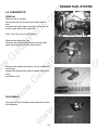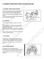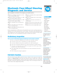
1
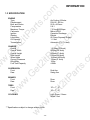
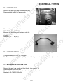
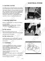
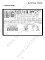
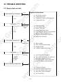
om
rts
.c
om
tP
ar
ts
.c
ar
ts
.c
tP
a
2i
w
.G
et
2i
ETON America
.G
et
w
Sierra DXL-90
w
2i
tP
.G
et
w
w
Service Manual
w
w
Rev 2.0.0
w
Spartanburg, SC 29303
06/30/2000
w
w
.G
et
w
ar
ts
.c
2i
tP
rts
.c
om
tP
ar
ts
.c
2i
.G
et
tP
a
2i
.G
et
w
w
w
w
w
om
om
.G
et
2i
tP
2i
.G
et
w
w
w
w
w
w
ar
ts
.c
tP
a
.G
et
w
w
Page
5
9
16
17
21
23
28
33
45
51
54
58
rts
.c
om
Table of Contents
INFORMATION
MAINTENANCE
ENGINE REMOVAL AND INSTALLATION
ENGINE FUEL SYSTEM
ENGINE LUBRICATION AND COOLING SYSTEM
ENGINE COMBUSTION SYSTEM
TRANSMISSION SYSTEM
FRONT WHEEL AND STEERING SYSTEM
REAR WHEEL SYSTEM
FENDERS AND EXHAUST PIPE
ELECTRICAL SYSTEM
TROUBLE SHOOTING
2i
Section
1.
2.
3.
4.
5.
6.
7.
8.
9.
10.
11.
12.
tP
ar
ts
.c
TABLE OF CONTENTS
w
w
.G
et
w
ar
ts
.c
2i
tP
rts
.c
om
tP
ar
ts
.c
2i
.G
et
tP
a
2i
.G
et
w
w
w
w
w
om
om
1. INFORMATION
tP
ar
ts
.c
1.1 SAFETY
INFORMATION
Gasoline is extremely flammable and is explosive under certain condition. Do not smoke or
allow sparks or flames in your work area.
rts
.c
om
Never run the engine in a closed area. The exhaust contains poisonous carbon monoxide
gas that may cause loss of consciousness and lead to death.
The battery electrolyte contains sulfuric acid. Protect your eyes, skin and clothing. If you
contact it, flush thoroughly with water and call a doctor if electrolyte gets in your eyes.
2i
1.2 NOTES
w
w
w
w
.G
et
w
w
ar
ts
.c
2i
tP
.G
et
w
2i
w
tP
a
.G
et
All information, illustrations, directions and specifications included in this publication are base on
the latest product information available at the time of approval for printing.
E-TON Dynamic Technology Industry Co., Ltd. reserves the right to make changes at any time
without notice and without incurring any obligation whatever.
No part of this publication may be reproduced without written permission.
1-1
om
tP
ar
ts
.c
1.3 SPECIFICATION
tP
a
2i
.G
et
2i
tP
Dual Arm
Swing Arm
Drum
Drum
w
w
BRAKES
Front
Rear
1,510mm(59.4inch)
860mm(39.3inch)
950mm(37.4inch)
630mm(24.8inch)
1040mm(40.9inch)
130mm(5.1inch)
102kg
4.0liter
TIRES
Front
Rear
ar
ts
.c
2i
.G
et
w
.G
et
19" x 7" - 8"
19" x 7" - 8”
w
Light Green / Green
White / Red
w
w
COLORING
***Specifications subject to change without notice.
w
w
CHASSIS
Overall
Overall Width
Overall Height
Seat Height
Wheel base
Ground Clearance
85kg/95kg
Fuel Tank Capacity
Air-Cooling 2-Stroke
DXL-90 - 82.5cc
50.0 x 42.0mm
5.8:1
7.2 N-m@6000rpm
Mikuni VM16
Capacitor Discharge
Electric
Oil Pump Separate Supply
1. 0 liter
Automatic (C.V.T V-belt)
rts
.c
om
ENGINE
Type
Displacement
Bore and Stroke
Compression
Maximum Torque
Carburetor
Ignition
Starting
Lubrication
Oil Capacity
Transmission
SUSPENSION
Front
Rear
INFORMATION
1-2
om
1.4 SERIAL NUMBER
INFORMATION
tP
a
.G
et
2i
rts
.c
om
tP
ar
ts
.c
The frame serial number is stamped on the front of the frame.
The engine serial number is stamped on the left side of the crankcase.
.G
et
w
w
Engine serial number
w
w
w
w
ar
ts
.c
2i
tP
.G
et
w
2i
w
Frame serial number
1-3
om
2i
FRAME
Handlebar upper holder bolt
Steering shaft nut
Steering shaft bushing holder nut
Wheel rim bolt
Tie rod lock nut
King pin nut
Handlebar lower holder nut
Front wheel bolt
Front axle nut
Front brake arm nut
Rear brake arm nut
Rear axle nut
Rear wheel bolt
Exhaust muffler mounting bolt
Engine hanger bolt
24-30 N.m (17.7-22.1 lb./ft)
50-60 N.m (36.9-44.3 lb./ft)
24-30 N.m (17.7-22.1 lb./ft)
18-25 N.m (13.3-18.4 lb./ft)
35-43 N.m (25.8-31.7 lb./ft)
30-40 N.m (22.1-29.5 lb./ft)
40-48 N.m (29.5-35.4 lb./ft)
24-30 N.m (17.7-22.1 lb./ft)
55-65 N.m (40.6-47.9 lb./ft)
4-7 N.m ( 3.0- 5.2 lb./ft)
7-12 N.m ( 5.2- 8.9 lb./ft)
60-80 N.m (44.3-59.0 lb./ft)
24-30 N.m (17.7-22.1 lb./ft)
30-35 N.m (22.1-25.8 lb./ft)
24-30 N.m (17.7-22.1 lb./ft)
w
w
w
w
.G
et
w
w
2i
tP
.G
et
2i
tP
a
.G
et
w
w
28-30 N.m (20.7-22.1 lb./ft)
12-19 N.m (8.9-14.0 lb./ft)
20-30 N.m (14.8-22.1 lb./ft)
8-12 N.m (5.9- 8.9 lb./ft)
rts
.c
om
tP
ar
ts
.c
ENGINE
Cylinder head nut
Spark plug
Cylinder head bolt
Alternator bolt
ar
ts
.c
1.5 TORQUE VALUES
INFORMATION
1-4
om
2. MAINTENANCE
2i
.G
et
tP
a
2.1 MAINTENANCE DATA
SPECIFICATION
THROTTLE LEVER FREE PLAY:
IDLE SPEED:
BRAKE LEVER FREE PLAY:
DRIVE CHAIN SLACK
FRONT/REAR TIRE SIZE
FRONT/REAR TIRE PRESSURE
TOE-IN
5-10 mm
1800±100 rpm
15-25 mm
10-25 mm
19X7-8 / 19X7-8
2.2± 0.3 psi(0.15 kgf/cm2)
5±10 mm
TORQUE VALUES
SPARK PLUG
TIE-ROD LOCK NUT
12-19 N.m
35-43 N.m
2i
tP
w
.G
et
w
w
JASO FC Grade or same degree oil
SAE 40
w
w
w
ENGINE OIL
GEAR LUBRICATION OIL
ar
ts
.c
0.6-0.7 mm
NGK BPR7HS
2i
SPARK PLUG:
PARK PLUG GAP:
RECOMMENDED SPARK PLUGS:
.G
et
w
w
rts
.c
om
tP
ar
ts
.c
2.1 MAINTENANCE DATA
2.2 MAINTENANCE SCHEDULE
2.3 FUEL TUBE
2.4 THROTTLE OPERATION
2.5 THROTTLE CABLE ADJUSTMENT
2.6 AIR CLEANER
2.7 SPARK PLUG
2.8 IDLE SPEED
2.9 DRIVE CHAIN
2.10 BRAKE SYSTEM
2.11 WHEELS AND TIRES
2.12 STEERING SYSTEM
2.13 TOE-IN
2.14 GEAR OIL
MAINTENANCE
2-1
tP
ar
ts
.c
The maintenance intervals in the follow table is based upon average riding, conditions. Riding in
unusually dusty areas, require more frequent servicing
INITIAL SERVICE
(First week)
REGULAR SERVICE
(Every 30 operating days)
2i
.G
et
2.3 FUEL TUBE
w
2.4 THROTTLE OPERATION
w
w
w
w
.G
et
Inspect for smooth throttle lever full opening and automatic full closing in all steering positions.
Inspect if there is no deterioration, damage or kinking
in the throttle cable, replace it if necessary.
Check the throttle lever, free play is 5-10 mm at the tip
of the throttle lever.
Disconnect the throttle cable at the upper end.
Lubricate the cable with commercially lubricant to prevent premature wear.
2-2
I
I
I
R
2i
tP
w
Inspect the fuel lines for deterioration, damage or leakage and replace if necessary.
EVERY
Year
I
ar
ts
.c
tP
a
.G
et
2i
rts
.c
om
FUEL LINE
THROTTLE OPERATION
I
I
AIR CLEANER
C
SPARK PLUG
I
CARBURETOR IDLE SPEED
I
I
DRIVE CHAIN
I, L
I, L
BRAKE SHOE WEAR
BRAKE SYSTEM
I
I
NUT, BOLT, FASTENER
I
I
WHEEL
I
I
STEERING SYSTEM
SUSPENSION SYSTEM
C.V.T. AIR FILTER
C
GEAR OIL
Note - I: Inspect and Clean, Adjust, Lubricate or Replace, if necessary
C: Clean
L: Lubricate
R: Replace
w
w
om
2.2 MAINTENANCE SCHEDULE
MAINTENANCE
om
2.5 THROTTLE CABLE ADJUSTMENT
tP
a
.G
et
2i
Unscrew the air cleaner cover screws.
Pull out the air filter element from the air cleaner
case.
Wash the element in non-flammable solvent,
squeeze out the solvent thoroughly. Let it dry.
Soak the filter element in gear oil and then squeeze
out the excess oil.
Install the element into air cleaner carefully.
w
.G
et
w
w
.G
et
This spark plug located at the front of the engine.
Disconnect the spark plug cap and unscrew the
spark plug.
Check the spark plug electrodes for wear.
Change a new spark plug if the electrodes and insulator tip appear unusually fouled or burned.
Discard the spark plug if there is apparent wear or if
the insulator is cracked or chipped.
The spark plug gap shall keep in 0.6-0.7mm.
With the sealing washer attached, thread the spark
plug in by hand to prevent cross threading.
Tighten the spark plug with 12-19 N.m
2i
tP
2i
2.7 SPARK PLUG
2.8 IDLE SPEED
w
w
w
Connect a engine speed meter.
Warm up the engine, 10 minutes are enough.
Turn the idle-speed adjust screw on the carburetor
to obtain the idle speed. "Turn in" (clockwise) will
get higher speed. "Turn out" (counter clockwise) will
get lower speed.
IDLE SPEED: 1800±100 rpm
2-3
ar
ts
.c
2.6 AIR CLEANER
rts
.c
om
tP
ar
ts
.c
Slide the rubber cap of the adjuster off the throttle
Housing, loosen the lock nut and adjust the free
play of the throttle lever by turning the adjuster on
the throttle housing. Inspect the free play of the
throttle lever.
w
w
MAINTENANCE
om
2.9 DRIVE CHAIN
tP
ar
ts
.c
Inspect the chain slack. The standard is 5-15mm.
Clean the drive chain with kerosene and wipe it dry.
Inspect the drive chain for possible wear or damage.
Replace the chain, if it is worn excessively or damaged.
2i
.G
et
w
w
w
w
.G
et
w
w
2i
tP
Inspect the sprocket teeth. If it is excessive wear or
damage, replace it.
ar
ts
.c
tP
a
.G
et
When the drive chain becomes very dirty, it should
be removed, cleaned and lubricated by specify lubricator. Using commercial chain lubricant to lubricate
the drive chain.
5 - 15mm
rts
.c
om
2i
Adjust the chain slack.
Loose the lock bolts (4) then adjust the drive chain
slack by turn the adjusting nut. Tighten the four lock
bolts.
w
w
MAINTENANCE
2-4
om
2.10 BRAKE SYSTEM
2i
.G
et
w
2.11 WHEELS AND TIRES
2.12 STEERING SYSTEM
w
w
.G
et
w
Inspect the tire surfaces for cuts, nails or other
sharp objects.
Check the tire pressure at cold tire condition.
The standard of tire pressure is 2.2±0.3 psi. ( 015
kgf/cm2 )
2i
tP
Adjust the free play of the rear brake lever by turning the adjuster on the rear axle.
w
w
Check the free play of the steering shaft with the
front wheels, turned straight ahead.
When there is excessive play, inspect the tie-rod,
kingpin bushing and ball joint.
2-5
ar
ts
.c
tP
a
.G
et
Inspect the rear rake lever and cable for excessive
play or other damage.
Replace or repair if necessary.
Measure the free play of the rear brake lever at the
end of the lever. The standard is 15-25 mm.
rts
.c
om
2i
tP
ar
ts
.c
Inspect the front brake lever and cable for excessive
play or other damage.
Replace or repair if necessary.
Measure the free play of the brake lever at the end
of the brake lever. The standard of free play is 15-25
mm.
w
w
MAINTENANCE
om
2.13 TOE-IN
2i
w
w
w
w
.G
et
w
w
2i
tP
.G
et
If the toe-in is out of standard, adjust it by changing
the length of the tie-rods equally by turning the tierod while holding the ball joint.
Tighten the lock nuts.
Torque: 35-43 N.m
ar
ts
.c
tP
a
.G
et
2i
Carefully move the vehicle back, let the wheels have
turned 180 °, so the marks on the tires are aligned
with the axle center height.
Measure the distance between the marks.
Calculate the difference in the front and rear measurements.
Toe-in: 5±10mm
rts
.c
om
tP
ar
ts
.c
Let the vehicle on level ground and the front wheels
facing straight ahead.
Mark the centers of the tires to indicate the axle
center height.
Measure the distance between the marks.
w
w
MAINTENANCE
2-6
om
w
w
w
w
.G
et
w
w
ar
ts
.c
2i
tP
.G
et
w
2i
w
tP
a
.G
et
2i
Gear oil needs to be changed every year.
There is a gear oil release bolt at the rear of engine.
Unscrew this release bolt and can let the dirty oil
flow out.
The re-add oil hole is on the engine case beside
gear box.
rts
.c
om
tP
ar
ts
.c
2.14 GEAR OIL
MAINTENANCE
2-7
tP
ar
ts
.c
3.1 ENGINE SHOULD NOT BE REMOVED UNLESS IT IS
NECESsARY TO REPAIR OR MAKE ADJUSTMENTS TO THE
TRANSMISSION AND/OR COMBUSTION SYSTEM!
Disconnect the wire connectors. There are three
connectors for carburetor auto-choke, starter motor
and generator respectively.
Remove the drive chain cover. This is under the
chain.
Remove the drive chain retaining clip and master
link, and remove the drive chain.
Remove the three engine hanger nuts and bolts.
Remove the engine from the right side of frame.
2i
2i
tP
.G
et
w
.G
et
w
3.3 ENGINE INSTALLATION
Engine installation is essentially the reverse order of
removal.
The torque of engine hanger bolt is 24-30 Nm
Route the wires and cable in reverse order properly.
w
w
w
w
ar
ts
.c
tP
a
.G
et
2i
Remove the seat and rear fender. (See chapter 10)
Remove the spark plug cap from the spark plug.
Remove the exhaust pipe.
Disconnect the carburetor cable by unscrew two
screws on top of the carburetor.
Take off oil pump cable from the oil pump control
plate.
Oil pump is under the right side of engine.
rts
.c
om
3.2 ENGINE REMOVAL
w
w
ENGINE
om
3. ENGINE REMOVAL AND INSTALLATION
3-1
ENGINE FUEL SYSTEM
om
4. ENGINE FUEL SYSTEM
tP
ar
ts
.c
4.1 TROUBLESHOOTING
NO FUEL IN TANK
NO FUEL TO CYLINDER
TOO MUCH FUEL GO INTO CYLINDER
NO SPARK AT PLUG
AIR CLEANER CLOGGED
ENGINE IDLES ROUGH,
STALLS OR RUNS POORLY
IMPROPER ADJUSTMENT TO IDLE SPEED SCREW
IGNITION MALFUNCTION
FUEL/AIR MIXTURE RATIO NO GOOD
AIR CLEANER DIRTY
INSULATOR LEAKS
FUEL TANK CAP BREATHING HOLE CLOGGED
.G
et
2i
rts
.c
om
ENGINE CAN NOT START
w
2i
FLOAT NEEDLE VALVE IN CARBURETOR FAULTY
FLOAT LEVEL TOO HIGH
AIR DUCT IN CARBURETOR IS CLOGGED
AIR CLEANER DIRTY
2i
tP
.G
et
w
RICH MIXTURE
ar
ts
.c
FUEL JET OF CARBURETOR CLOGGED
FUEL TANK CAP BREATHING HOLE CLOGGED
FUEL FILTER CLOGGED
FUEL FLOWS IN THE TUBE ROUGHLY
FLOAT LEVEL IN CARBURETOR TOO LOW
tP
a
LEAN MIXTURE
w
w
REMOVAL
Remove the seat and rear fender.
Disconnect the fuel line from the carburetor.
Remove the fuel tank cap and front fender.
Unscrew the fuel tank fixed bolts.
.G
et
w
4.2 FUEL TANK
w
w
w
Note: Keep gasoline away from flames or sparks.
Wipe up spilled gasoline at once.
4-1
om
ENGINE FUEL SYSTEM
4.3 CARBURETOR
tP
a
.G
et
2i
Remove the carburetor cap.
Remove the throttle cable from the throttle valve
while depressing the throttle valve spring.
.G
et
w
w
2i
tP
.G
et
2i
Remove the needle clip retainer, the jet needle and
needle clip.
Inspect the throttle valve and jet needle surface for
wear.,
scratches or dirt.
w
DISASSEMBLY
w
w
Unscrew the float chamber screws and remove the
float chamber.
w
ar
ts
.c
Note: Turn fuel cup on (off) position
w
w
rts
.c
om
tP
ar
ts
.c
REMOVAL
Remove the air cleaner.
Disconnect the fuel line and auto-choke electric
wire.
Unscrew the intake pipe mounting bolts at the carburetor then remove the carburetor.
4-2
om
ENGINE FUEL SYSTEM
.G
et
w
w
2i
tP
.G
et
Clean all parts in solvent and blow it dry with compressed air.
Assembly is essentially the reverse order of disassembly.
THROTTLE VALVE ASSEMBLY
w
w
Install the needle clip on the jet needle.
Install the jet needle into the throttle valve.
Assemble the throttle cable, spring and the throttle
valve.
Align the throttle valve groove with the idle speed
adjust screw and install the carburetor cap to the
carburetor.
w
ar
ts
.c
2i
ASSEMBLY
w
w
w
tP
a
.G
et
2i
Disassembly the idle jet, main jet, idle speeds adjust
screw and idle mixture adjusts screw.
Inspect all the jets and screws for wear or damage.
Clean the passages and jets with compressed air.
rts
.c
om
tP
ar
ts
.c
Disassembly the float arm pin, float and float needle
valve.
Inspect the seat of the float needle valve for wear or
damage.
4-3
om
5. ENGINE LUBRICATION AND COOLING SYSTEM
.G
et
5.2 CAUTION
.G
et
w
w
The quantity of oil that is delivered from oil pump
increases with the engine speed and the carburetor
throttle open width. Oil pump is under the right side
of the engine and connected by a control cable of
throttle.
2i
tP
2i
.G
et
5.3 OIL PUMP
w
5.4 COOLING SYSTEM
w
w
The engine-cooling fan circulates the air.
The cooling fan is on the right-hand side of engine.
The air is forced to flow through cylinder fin and
cylinder head. So, the cylinder and piston will not
overheat.
w
w
w
tP
a
Having enough oil supply to engine is very important.
If the oil quantity is not enough, this engine will be
serious scratched, and then this engine will stop,
even cannot work again.
When this engine is serious scratched, you need to
change the piston, piston rings and cylinder together.
Also you need to check the combustion system and
lubrication system carefully.
5-1
ar
ts
.c
2i
The engine crankshaft drives the pump gears of oil
pump. The gears rotate the plunger shaft in oil
pump. This shaft sent the lubricating oil into the
crankcase to mix with the air-fuel mixture and flow
evenly.
The oil drops and foam cover the cylinder inner wall,
piston surface and piston rings.
rts
.c
om
tP
ar
ts
.c
5.1 ENGINE LUBRICATION SYSTEM
om
ENGINE LUBRICATION AND COOLING SYSTEM
tP
ar
ts
.c
5.5 TROUBLESHOOTING
NO ENOUGH OIL SUPPLY TO ENGINE
THE OIL LEVEL IN OIL TANK IS TOO LOW.
OIL TUBES WERE NOT FIXED WELL.
OIL HAS LEAK FROM TUBE ENDS.
OIL TUBES WERE BROKEN.
rts
.c
om
OIL TUBES WERE CLOGGED.
OIL PUMP NOT WORKING.
tP
a
.G
et
2i
w
w
w
w
w
.G
et
w
w
2i
tP
.G
et
w
ar
ts
.c
EXTERNAL OIL LEAKS
WORN CYLINDER HEAD GASKET
WORN PISTON RINGS
2i
ALWAYS LOW OIL LEVEL
IN LUBRICATE OIL TANK
5-2
om
ENGINE COMBUSTION SYSTEM
tP
ar
ts
.c
6. ENGINE COMBUSTION SYSTEM
6.1 TROUBLESHOOTING
CYLINDER HEAD
HEAD GASKET LEAKING OR DAMAGED
WARPED OR CRACKED CYLINDER HEAD
CYLINDER OR PISTON RINGS WORN OUT
HIGH COMPRESSION
EXCESSIVE CARBON BUILD-UP ON PISTON
HEAD OR COMBUSTION CHAMBER
2i
PISTON AND CYLINDER WORN OUT
EXCESSIVE CARBON BUILD-UP
tP
a
.G
et
EXCESSIVE NOISE
CYLINDER OR PISTON RINGS WORN OUT
IMPROPER INSTALLATION OF PISTON RINGS
PISTON OR CYLINDER WALL SCORED OR
SCRATCHED
2i
EXCESSIVE CARBON BUILD-UP ON THE PISTON
OR COMBUSTION CHAMBER
ENGINE COOLING SYSTEM (FAN, CYLINDER
COVER) WORKS BADLY.
OIL SUPPLY IS OUT OF ORDER.
WRONG IGNITION TIMING
w
w
w
w
.G
et
w
w
2i
tP
.G
et
OVERHEATING
ar
ts
.c
EXCESS SMOKE
w
w
rts
.c
om
LOW COMPRESSION
6-1
om
ENGINE COMBUSTION SYSTEM
6.2 CYLINDER AND PISTON REMOVAL
w
Note: Don't let the clip drop into engine crankcase.
w
.G
et
6.3 CYLINDER AND PISTON INSPECTION
2i
tP
w
.G
et
2i
Remove the cylinder head.
Remove the cylinder carefully, then you can see the
whole piston.
Remove one piston pin clip.
Remove the piston and piston pin.
Spread each piston ring and remove it by lifting up
at a point just opposite the gap.
w
w
w
Inspect the cylinder bore for wear or damage.
Measure the cylinder inner diameter at three levels
in X and Y-axis.
Taper limit: 0.10 mm
Out of round: 0.10 mm
6-2
ar
ts
.c
tP
a
.G
et
2i
Remove the intake pipe mounting bolts.
Remove the cylinder bolt nuts.
w
w
rts
.c
om
tP
ar
ts
.c
Remove the seat and rear fender.
Remove the exhaust pipe.
Remove the spark plug cap.
Disconnect the wire.
Drag out the engine.
Disassemble the air cleaner and carburetor.
om
ENGINE COMBUSTION SYSTEM
.G
et
w
w
Measure the piston outer diameter at 10 mm high
from the skirts bottom.
Service limit:
39.9 mm (for 50cc engine)
49.9 mm (for 90cc engine)
w
w
w
ar
ts
.c
2i
tP
.G
et
2i
Measure the clearance between ring and groove.
Service limit: 0.09 mm
w
w
w
tP
a
.G
et
2i
Insert each piston ring into the cylinder, and measure the end gap.
Service limit: 0.5 mm
rts
.c
om
tP
ar
ts
.c
Check the cylinder head mating surface for warp
with a straight edge and feeler gauge.
Service limit: 0.10 mm
6-3
tP
a
6.4 INSTALLATION
Install the piston rings with the marks facing up.
Do not damage the piston rings by spreading the
ends too far.
2i
w
.G
et
w
w
Apply some oil to inside of the connecting rod small
end.
Install the piston, piston pin and clip.
Install the piston with the arrow mark facing the
exhaust pipe.
Do not align the piston pin clip end gap with the piston cutout. Install a new cylinder gasket.
Apply a thin coat of engine oil to the piston rings
and cylinder wall.
2i
tP
.G
et
Clean the cylinder gasket surface being careful not
to drop any gasket material into the crankcase.
w
w
w
Install the cylinder, compressing the piston rings.
Replace a new cylinder head gasket.
Install the cylinder head.
Tighten the cylinder-mounting bolt.
The torque is 10-14N.m
6-4
ar
ts
.c
.G
et
2i
Measure the connecting rod small end inner diameter with a small hole gauge.
Service limit: 14.06 mm (for 50cc engine)
15.06 mm (for 90cc engine)
rts
.c
om
tP
ar
ts
.c
Pin outer diameter service limit:
9.96 mm (for 50cc engine)
11.96 mm (for 90cc engine)
Pin bore service limit:
10.04 mm (for 50cc engine)
12.04 mm (for 90cc engine)
w
w
om
Measure the piston pin bore, and the piston pin
outer diameter.
om
TRANSMISSION SYSTEM
7. TRANSMISSION SYSTEM
tP
ar
ts
.c
7.1 TROUBLESHOOTING
BELT WORN
FRONT PULLEY WORN OR BROKEN
LINING OF CLUTCH WORN
DOES NOT RUN AT HIGH SPEED
BELT WORN
ROLLERS WORN
SPRING OF REAR PULLEY IS DISTORTED
.G
et
2i
rts
.c
om
SCOOTER DOES NOT MOVE
AFTER ENGINE START
w
w
w
w
.G
et
w
w
ar
ts
.c
2i
tP
.G
et
w
2i
w
tP
a
7.2 THE PARTS DRAWING OF TRANSMISSION SYSTEM
7-1
om
TRANSMISSION SYSTEM
2i
tP
a
.G
et
7.4 AUTOMATIC CONTINUOUS VARIABLE TRANSMISSION
ar
ts
.c
2i
The torque of crank-shaft drive the front pulley
The torque (drive) pulley turn the belt
The belt drive the rear (driven) pulley
The force through the clutch shoe, clutch housing and drive shaft
The drive shaft turn the idle gear in gearbox
Turning speed reduced by final-gear and transmits to rear-axle shaft to move rear wheel
.G
et
w
w
w
w
.G
et
w
w
When engine speed increase, the drive pulley will be push into belt by the centrifugal
force from six rollers.
Then the pitch circle of belt in drive pulley
will be larger.
The belt at driven pulley is forced to move
to the center of shaft, and then the radius of
pitch circle is decreased.
The transmission ratio is therefore altered
by the alteration of pitch circle's radius.
(In the drawing, "H" means high speed, "L"
means low speed)
2i
tP
This transmission is the combination of automatic centrifugal clutch and V-belt continuous variable
transmission, which can change the transmission ratio automatically.
w
w
rts
.c
om
tP
ar
ts
.c
7.3 PATH OF POWER TRANSMISSION
7-2
om
TRANSMISSION SYSTEM
7.5 CONTINUOUS VARIABLE TRANSMISSION
tP
ar
ts
.c
V-Belt
Drive Pulley
.G
et
2i
Due to the increasing engine speed,
the rollers push the movable drive
face by centrifugal force. This then
applies pressed to the belt and
enlarges its turning radius.
The aluminum fan is installed on the
exterior of fixed drive face. It can reduce the belt temperature.
2i
w
w
w
w
.G
et
w
w
The torque received by the
Drive shaft will be transmitted
by the speed reduction of two
sets to rear axle shaft.
The first gear ratio is 36/13.
The second gear ratio is 48/12.
2i
tP
.G
et
7.6 GEAR BOX
ar
ts
.c
tP
a
Because the revolving radius of V-Belt at the Drive End is enlarged, the Face Comp Movable Drive
is squeezed out by the V-Belt at the Driven End to shorten the revolving radius.
There is a Torque Cam on the Movable Drive Face.
Torque Cam is loaded from outside. When the outside load is higher than the engine's output, the
pulley of fixed shaft and belt slip to make the Movable Drive Face move along the inner side of Cam
and compensate to increase to high torque (toward to low speed) and make the engine maintain
smooth running with original revolution.
w
w
rts
.c
om
Made of rubber fiber, resistant to
head, pressure and abrasion.
The inner side of the Belt is toothed.
7-3
om
TRANSMISSION SYSTEM
7.7 ELECTRIC SELF-STARTER MECHANISM
2i
.G
et
w
7.8 KICK STARTER
2i
tP
This kick-starter arm is on the left side of engine.
When the kick-starter arm is kicked, the gear of
start shaft will drive the kick starter to revolve the
crank shaft to start the engine. After the engine is
started, the kick-started will stop transfer the
power to the kick-starter driven gear.
When he kick-starter lever is released, the kickstarter gear will go back to its original position.
w
.G
et
w
w
w
w
w
ar
ts
.c
w
tP
a
.G
et
2i
rts
.c
om
tP
ar
ts
.c
Starter Motor is installed on the upper side of engine.
The starter motor can act only when the left hand brake is applied.
7-4
om
TRANSMISSION SYSTEM
w
w
w
w
.G
et
w
w
ar
ts
.c
2i
tP
.G
et
w
2i
w
tP
a
.G
et
2i
Remove the engine clutch cover by unscrew the
fixed bolts.
Check the belt for wear. If necessary, replace the
belt.
Disassembly the front drive pulley, check the six
rollers for wear.
If necessary, replace the rollers.
rts
.c
om
tP
ar
ts
.c
7.9 DISASSEMBLY AND CHECK OF C.V.T.
SYSTEM
7-5
om
FRONT WHEEL AND STEERING SYSTEM
8. FRONT WHEEL AND STEERING SYSTEM
2i
tP
w
w
w
w
w
.G
et
w
ar
ts
.c
tP
a
.G
et
2i
Front Wheels
w
w
.G
et
2i
rts
.c
om
tP
ar
ts
.c
8.1 THE PARTS DRAWING OF FRONT WHEELS AND STEERING SYSTEM
8-1
Steering System
om
FRONT WHEEL AND STEERING SYSTEM
tP
ar
ts
.c
8.2 TROUBLE SHOOTING
FAULTY TIRE
STEERING SHAFT HOLDER TOO TIGHT
INSUFFICIENT TIRE PRESSURE
FAULTY STEERING SHAFT BEARINGS
DAMAGED STEERING SHAFT BEARING
FRONT WHEEL WOBBLING
FAULTY TIRE
WORN FRONT BRAKE DRUM BEARING
BENT RIM
AXLE NUT NOT TIGHTENED PROPERLY
2i
rts
.c
om
HARD STEERING
INCORRECT BRAKE ADJUSTMENT
STICKING BRAKE CABLE
.G
et
BRAKE DRAG
2i
w
.G
et
BRAKE SHOES WORN
WORN BRAKE DRUM
BRAKE LINING OILY, GREASY OR DIRTY
IMPROPER BRAKE ADJUSTMENT
FAULTY FRONT SWING ARM BUSHINGS
IMPROPERLY INSTALLED FRONT SWING ARMS
BENT FRONT SHOCK ABSORBER SWING ROD
.G
et
w
HARD SUSPENSION
2i
tP
LOOSE FRONT SUSPENSION FASTENER
BINDING SUSPENSION LINK
w
FRONT SUSPENSION NOISE
SOFT SUSPENSION
WEAK FRONT SHOCK ABSORBER SPRINGS
WORN OR DAMAGE FRONT SWING ARM
BUSHINGS
w
w
w
w
w
POOR BRAKE PERFORMANCE
ar
ts
.c
BENT TIE RODS
WHEEL INSTALLED INCORRECTLY
UNEQUAL TIRE PRESSURE
BENT FRAME
WORN SWING ARM PIVOT BUSHINGS
tP
a
STEERS TO ONE SIDE
8-2
om
FRONT WHEEL AND STEERING SYSTEM
8.3 HANDLEBAR
w
w
.G
et
INSTALLATION
Put the handlebar on the lower holders.
Make sure the handlebar punch mark with the top of
the handlebar lower holders.
Install the handlebar upper holders with the L or R
marks facing forward.
Tighten the forward bolts first, and then tighten the
rear bolts.
Install the handlebar upper holder's cover.
w
w
w
ar
ts
.c
2i
tP
.G
et
2i
Remove the bolts attaching the upper holder cover.
Remove the handlebar holder and handlebar.
w
w
w
tP
a
.G
et
2i
Remove engine switch housing on the left handle
bar.
Remove rear brake level bracket.
rts
.c
om
tP
ar
ts
.c
REMOVAL
Remove the throttle lever housing on the right handle bar.
Remove brake lever bracket.
8-3
om
FRONT WHEEL AND STEERING SYSTEM
tP
a
.G
et
Aligning the split line of the throttle housing and
holder with the punch mark.
Tighten the screw securely
2i
REMOVAL
2i
tP
INSTALLATION
.G
et
Raise the front wheels off the ground by placing a
block under the frame.
Remove the front wheel nuts, washer and wheels.
.G
et
w
w
Install and tighten the four-wheel nuts
Torque: 50-60 N.m
Remember put a cotter pin in the castle nut.
w
8.5 FRONT BRAKES
w
Remove the front wheel.
Remove the brake drum.
w
FRONT BRAKE INSPECTION
w
w
w
8.4 FRONT WHEEL
ar
ts
.c
2i
Install the rear brake lever bracket, aligning the boss
with the hole.
Tighten the screw securely.
rts
.c
om
tP
ar
ts
.c
Install the switch housing, aligning the boss with the
hole.
Tighten the upper screw first then tighten the lower
one.
8-4
om
FRONT WHEEL AND STEERING SYSTEM
2i
w
w
2i
tP
.G
et
Turn the inner race of each bearing with fingers.
The bearings should turn smoothly and quietly.
If the race does not turn smoothly or quietly, remove
and discard the bearings
.
.G
et
BRAKE PANEL REMOVAL
w
w
w
Disconnect the brake cable from the brake arm.
Remove the brake panel from the knuckle.
w
ar
ts
.c
tP
a
.G
et
2i
Measure the brake drum inner diameter.
The maximum limit: 86 mm
w
w
rts
.c
om
tP
ar
ts
.c
Measure the brake lining thickness.
The minimum limit: 1.5 mm
If they are thinner than the minimum limit, replace
the brake lining.
8-5
tP
a
.G
et
Apply grease to the brake cam and anchor pin and
install the cam in the brake panel.
Soak the felt seal in the engine oil and install the
seal on the brake cam.
2i
w
Install the brake panel on the knuckle.
Connect the brake cable to the brake arm.
.G
et
w
w
2i
tP
.G
et
Install the brake arm on the cam by aligning the
punch mark and the groove on the cam.
Tighten the brake arm bolt and nut.
Torque: 4-7 N.m
Install the return spring.
w
w
Install the brake arm cover.
Tighten the screws securely.
Position the brake shoes in their original locations
and install the brake shoe spring.
Install the brake drum and front wheel.
Install the castle nut and cotter pin.
w
ar
ts
.c
2i
INSTALL BRAKE PANEL
rts
.c
om
tP
ar
ts
.c
Remove brake arm and cam.
Remove return spring.
Remove indicator plate and felt seal.
w
w
om
FRONT WHEEL AND STEERING SYSTEM
8-6
8.6 STEERING SYSTEM
tP
ar
ts
.c
REMOVAL OF KINGPIN AND TIE-ROD
w
KINGPIN INSPECTION
w
w
w
Inspect the kingpin for damage or cracks.
.G
et
w
w
Inspect the tie-rod for damage or bending.
Inspect the ball joint rubbers for damage, wear or
deterioration.
Turn the ball joints with fingers. The ball joints
should turn smoothly and quietly.
2i
tP
2i
.G
et
TIE-ROD INSPECTION
8-7
ar
ts
.c
tP
a
.G
et
Take off the rubber cap on the kingpin and remove
the cotter pin on the kingpin.
Unscrew the castle nut and remove the kingpin.
rts
.c
om
2i
Remove the front wheels and brakes plates.
Remove the four self-lock nuts from the tie-rod ball
joints and take off the two tie-rods.
w
w
om
FRONT WHEEL AND STEERING SYSTEM
om
FRONT WHEEL AND STEERING SYSTEM
STEERING SHAFT REMOVAL
tP
a
2i
STEERING SHAFT INSPECTION
w
w
2i
tP
.G
et
Inspect the steering shaft for damage or cracks.
Measure the steering shaft outer diameter in the
location of the bushing.
Minimum limit: Ø22.0 mm
.G
et
STEERING SHAFT BEARING INSPECTION
w
w
w
Turn the shaft bearing with finger.
The bearing is on the front part of frame.
The bearing should turn smoothly and quietly.
Also check that the bearing outer race fits in the
holder.
Replace the bearing if necessary.
w
w
w
.G
et
2i
Remove the steering shaft.
Remove the bushing from the shaft.
Inspect the bushing for damage or wear, replace if
necessary.
Measure the bushing inner diameter.
Maximum limit: Ø22.8 mm
ar
ts
.c
STEERING SHAFT BUSHING INSPECTION
rts
.c
om
tP
ar
ts
.c
Remove the handle bar and handle bar cover. (See
paragraph 8-1)
Remove the front fender. (See paragraph 10-1)
Unscrew the steering shaft fixed out below shaft.
Pull steering shaft carefully.
8-8
INSTALLATION OF STEERING SHAFT
tP
a
INSTALLATION OF TIE-ROD
2i
.G
et
2i
Install the steering shaft nut and tighten it.
This nut is under this steering shaft.
Torque: 50-60 N.m
w
w
w
w
.G
et
w
w
2i
tP
.G
et
Install the ball joint with " L" mark on the steering
shaft side.
Install the tie-rod with the mark on the wheel side.
ar
ts
.c
rts
.c
om
tP
ar
ts
.c
Install the steering shaft with the bushing.
Apply grease to the bushing.
Install the bushing holder and tighten the nuts.
Torque: 24-30 N.m
w
w
om
FRONT WHEEL AND STEERING SYSTEM
8-9
om
REAR WHEEL SYSTEM
9. REAR WHEEL SYSTEM
w
w
w
w
.G
et
w
w
ar
ts
.c
2i
tP
.G
et
w
2i
w
tP
a
.G
et
2i
rts
.c
om
tP
ar
ts
.c
9.1 THE PARTS DRAWING OF REAR WHEEL SYSTEM
9-1
om
REAR WHEEL SYSTEM
9.2 TROUBLESHOOTING
BRAKE SHOES ARE WORN
BAD BRAKE ADJUSTMENT
BRAKE LINING ARE OILY, GREASY OR DIRTY
BRAKE DRUMS ARE WORN
BRAKE ARM SETTING IS IMPROPERLY ENGAGE
rts
.c
om
tP
ar
ts
.c
BAD BRAKE PERFORMANCE
AXLE IS NOT TIGHTENED WELL
BENT RIM
AXLE BEARINGS ARE WORN
FAULTY TIRES
REAR AXLE BEARING HOLDER IS FAULTY
.G
et
2i
VIBRATION OR WOBBLE
2i
w
.G
et
w
w
w
Remove the brake drum cover.
Remove the acle collar and brake drum.
.G
et
w
w
2i
tP
Let the rear wheels off the ground.
Release the cotter pin, axle nut and washer.
Release the wheel and wheel hub.
w
w
9.3 REMOVE REAR WHEEL AND BRAKE
ar
ts
.c
INCORRECT BRAKE ADJUSTMENT
STICKING BRAKE CAM
STICKING BRAKE CABLE
tP
a
BRAKE DRAG
9-2
tP
a
.G
et
2i
Check the brake drum for damage.
Replace if necessary.
Check the brake drum inner diameter.
The maximum limit is 131 mm.
2i
9.4 DRIVE MECHANISM REMOVAL
AND INSPECTION
w
.G
et
w
w
2i
tP
.G
et
Remove the rear wheel and the rear brake
Remove the drive chain under cover.
w
w
Disassemble the chain retaining clips and master
link.
w
ar
ts
.c
rts
.c
om
tP
ar
ts
.c
Check the brake lining thickness.
The minimum limit is 2.0 mm.
w
w
om
REAR WHEEL SYSTEM
9-3
om
REAR WHEEL SYSTEM
.G
et
w
w
2i
tP
Add grease to the dust seal lips and install dust
seals.
Assemble the rear axle and the driven sprocket.
w
w
Assemble the drive chain on the driven sprocket.
Assemble the master link and retaining clip.
Note the retaining clip direction.
Install the drive chain cover.
Assemble the chain under cover.
w
ar
ts
.c
2i
.G
et
INSTALLATION
w
w
w
tP
a
.G
et
2i
Let the rear axle lie in V-blocks and check the run
out.
The run out limit is 0.5 mm
Check the turning of bearing with fingers.
The bearings should turn smoothly and quietly.
Replace if necessary.
rts
.c
om
tP
ar
ts
.c
Disassemble the driven sprocket, axle and sprocket
collar.
Check the driven sprocket for damage or wear.
9-4
om
REAR WHEEL SYSTEM
tP
ar
ts
.c
9.5 REAR BRAKE AND WHEEL
INSTALLATION
w
.G
et
w
w
w
w
w
Assembly the brake drum, axle collar and brake
drum cover. Assemble the wheel.
Tighten the rear axle nut with 60-80 N.m.
Install a new cotter pin.
Adjust rear brake level free play.
Adjust chain slack.
9-5
ar
ts
.c
Install the brake shoes and springs to their original
positions.
2i
tP
.G
et
w
2i
w
tP
a
.G
et
2i
Assembly the brake arm aligning the punch marks
on the cam and the arm.
Tighten the brake arm bolt and nut with 7-12 N.m
torque.
Install the
adjusters.
rts
.c
om
Install the brake panel
Add grease to the brake cam and anchor pin.
Install the brake arm spring and oil seal.
2i
10.2 REAR FENDERS REMOVE
.G
et
w
Procedure for removal of the rear fender:
Unscrew the four bolts, which connect the front
fender and rear fender.
2i
tP
w
.G
et
Pull the “Seat Release Bae” to unlatch the seat for
removal. This seat release bar is located under the
right hand side rear fender
w
Unscrew the two bolts, which fix the rear fender on
the fixed plate just under rear Fender. (See the upleft picture.)
w
Unscrew the six screws which connect with the foot
rest plate
w
w
Pull the rear fender toward the rear of the unit until
the fender can be removed.
10-1
ar
ts
.c
10.1 FENDERS DRAWING
w
w
tP
a
.G
et
2i
rts
.c
om
tP
ar
ts
.c
om
FENDERS AND EXHAUST PIPE
10. FENDERS AND EXHAUST PIPE
10.3 FRONT FENDER REMOVE
tP
a
.G
et
Remove the seat by pulling the seat release bar
under the rear fender. Remove the handle bar
assembly headlight and handlebar cover.
Take off the central-front-trim fender.
Unscrew the six screws, which connect with footrest
plate. Unscrew the four screws, which connect with
the frame. Two screws are just behind the fuel tank;
the other two screws are above the front absorbers.
2i
w
w
w
w
2i
tP
.G
et
w
w
.G
et
10.4 EXHAUST PIPE DRAWING
10-2
ar
ts
.c
2i
Unscrew the two fixed screws under the front fender, just above front wheels. (See up-left picture)
Unscrew the two fixed screws beside the oil tank.
(See down-left picture)
Unscrew the fuel tank cap. Then the front fender
can be removed.
rts
.c
om
tP
ar
ts
.c
Pull the front fender upward.
Remove the handle bar assembly and handle bar
cover.
w
w
om
FENDERS AND EXHAUST PIPE
om
FENDERS AND EXHAUST PIPE
10.5 EXHAUST PIPE REMOVE
w
w
w
w
Installation is the reverse order of removal.
Torque: Exhaust muffler bolts 30-35 N.m
After installation, make sure that three are no
exhaust leaks
2i
tP
10.6 EXHAUST PIPE INSTALLATION
.G
et
w
w
.G
et
w
2i
w
Remove the exhaust pipe mounting bolts that fixed
on the engine.
Remove the exhaust pipe carefully.
10-3
ar
ts
.c
tP
a
.G
et
2i
You need remove the seat, rear fender and footrest
plate, before you take off the exhaust pipe.
Unscrew the two exhaust pipe bolts that fixed with
engine.
rts
.c
om
tP
ar
ts
.c
Do not service the exhaust pipe while they are hot.
You must wait at least 15 minutes after turn off the
engine.
11. ELECTRICAL SYSTEM
om
11-1 Trouble Shooting
IMPROPER IGNITION TIMING
FAULTY SPARK PLUG
tP
ar
ts
.c
ENGINE STARTS BUT STOPS
ENGINE STOP SWITCH AT " OFF "
FAULTY IGNITION COIL
FAULTY GENERATOR
FAULTY CDI UNIT
POOR CONNECTION:
Between CDI and ignition coil
Between alternator and CDI unit
Between CDI and engine stop switch
Between ignition coil and spark plug
Between generator and CDI unit
IGNITION PRIMARY CIRCUIT
Faulty generator
Faulty CDI unit
Faulty alternator exciter coil
Loosen contacted terminals
Faulty ignition coil
IGNITION SECONDARY CIRCUIT
Faulty plug
Loosen contacted spark plug wire
IMPROPER IGNITION TIMING
Faulty generator Faulty CDI unit
w
w
CHARGING SYSTEM FAILURE
LOOSE BATTERY CONNECTION
LOOSE CHARGING SYSTEM CONNECTION
w
.G
et
ENGINE INTERMITTENT POWER
LOOSE, BROKEN OR SHORTED WIRE
FAULTY ALTERNATOR
FAULTY IGNITION SWITCH
2i
tP
.G
et
w
2i
w
tP
a
ENGINE STARTS BUT RUNS POORLY
ar
ts
.c
.G
et
2i
rts
.c
om
NO SPARK AT PLUG
DEAD BATTERY
FAULTY IGNITION SWITCH
LOOSE OR DISCONNECTED WIRE
w
STARTER MOTOR WILL NOT TURN
w
w
STARTER MOTOR AND ENGINE TURN
BUT ENGINE DOES NOT START
FAULTY IGNITION SYSTEM PROBLEMS
FAULTY ENGINE STOP SWITCH
11-1
om
11.2 IGNITION COIL
ELECTRICAL SYSTEM
.G
et
w
2i
w
tP
a
.G
et
Measure the primary coil resistance.
STANDARD: 0.1 - 0.3O(20?)
Measure the secondary coil resistance with the
spark plug cap
in place.
Standard: 7.4 - 11 kO(20?)
2i
tP
11.3 IGNITION TIMING
ar
ts
.c
2i
rts
.c
om
tP
ar
ts
.c
Remove the spark plug cap from the spark plug.
Disconnect the ignition coil primary wire.
11.4 ALTERNATOR EXCITER COIL
.G
et
w
w
w
The ignition advance is 15°± 3°/4000rpm
The Capacitive Discharge Ignition (CDI) system is factory pre-set and does not require adjustment.
w
w
w
Remove the seat / rear fender and front fender. (see chapter 10)
Disconnect the exciter coil wire.
Measure the resistance between the yellow / red wire and ground.
Standard: 460-700O (AT 20η 68η)
11-2
tP
a
.G
et
Battery is under the seat; you can see this battery
from the left side.
Measure the battery voltage using a voltmeter.
VOLTAGE: Fully charged: 13.1 V
Undercharged: Below 12.0 V
BATTERY REMOVAL
2i
.G
et
Remove the battery holder bolt nuts.
Disconnect the negative cable and then the position
cable and remove the battery.
w
Install the battery in the reverse order of removal.
After installing the battery, coat the terminals with
clean grease.
.G
et
w
11.7 CHARGING
2i
tP
BATTERY INSTALLATION
w
w
w
w
Connect the charge positive cable to the battery
position terminal. Connect the charge negative
cable to the battery negative terminal.
Using 0.9A-charging current about 5 hours.
(Normal charging)
Using 4A-charging current about 1 hour.
(Quick charging)
Keep flames and sparks away from a battery being
charged.
Quick charging should be limited to an emergency;
Normal charging is preferred.
11-3
ar
ts
.c
2i
11.6 BATTERY INSPECTION
rts
.c
om
tP
ar
ts
.c
The battery gives off explosive gases; keep sparks,
flames and cigarettes away. Provide adequate ventilation when charging or using the battery in an open
area. The battery contains sulfuric acid (electrolyte).
Contact with skin or eyes may cause severe burns.
Wear protective clothing and a face shield.
Electrolyte is poisonous. If swallowed drink large
quantities of water or milk and call a physician.
w
w
om
11.5 BATTERY CAUTION
ELECTRICAL SYSTEM
w
w
.G
et
w
11-4
ar
ts
.c
2i
tP
rts
.c
om
tP
ar
ts
.c
2i
.G
et
tP
a
2i
.G
et
w
w
w
w
w
om
11.8 WIRING DIAGRAMS
ELECTRICAL SYSTEM
om
12. TROUBLE SHOOTING
tP
ar
ts
.c
12.1 Engine does not start
Possible Problem Areas
N/G
Check Fuel Flow to Carburetor
Faulty Spark Plug
Fouled Spark Plug
Faulty C.D.I. Unit
Faulty Engine stop Switch
Poor connection, Broken or Shorted Wire
Broken or Shorted Ignition Coil
Broken or Shorted Spark Plug Wire
Faulty Pulse Generator
♦
♦
♦
♦
Worn Cylinder
Worn / Damaged piston Rings
Damaged Piston
Leaking Cylinder Head Gasket
♦
♦
♦
♦
♦
Auto Choke Off or Damaged
Auto Choke Power Wire not connected
Improperly Adjusted Air Screw
Improper Ignition Timing Adjustment
Fuel / Air mixture ratio is too lean
♦
♦
♦
♦
♦
Carburetor Flooded
Improperly Adjusted Air Screw
Fuel / Air mixture ration to rich
Auto Choke stuck or damaged
Air Cleaner Dirty
tP
a
N/G
2i
Low
Compression
.G
et
w
w
O.K.
Test Cylinder Compression
♦
♦
♦
♦
♦
♦
♦
♦
O.K.
N/G
w
Start Engine
Wet Plug
w
.G
et
w
Engine
does not
start
2i
tP
2i
.G
et
Weak or No
Spark
w
w
w
Remove and Inspect Spark Plug
12-1
ar
ts
.c
N/G
Test Spark
No Fuel in Fuel Tank
Clogged Float Valve
Clogged Fuel Tank Cap Breather Hose
Clogged Fuel Line
rts
.c
om
O.K.
♦
♦
♦
♦
om
TROUBLE SHOOTING
12.2 POOR PERFORMANCE AT LOW IDLE SPEED
tP
ar
ts
.c
Possible Problem Areas
N/G
Check Ignition Timing
rts
.c
om
O.K.
2i
.G
et
tP
a
N/G
.G
et
2i
Check for Intake Manifold Leak
w
w
O.K.
♦ Improper Air Screw Adjustment
♦ Fuel / Air mixture ratio to lean
♦ Deteriorated Insulator O-Ring
♦ Loose Carburetor
♦ Damaged Carburetor Gasket
♦
♦
♦
♦
♦
♦
♦
♦
Faulty Spark Plug
Fouled Spark Plug
Faulty C.D.I. Unit
Faulty Engine stop Switch
Poor connection, Broken or Shorted Wire
Broken or Shorted Ignition Coil
Broken or Shorted Spark Plug Wire
Faulty Pulse Generator
.G
et
Weak or
Intermittent Spark
w
w
w
w
w
w
N/G
2i
tP
O.K.
Test Spark
12-2
ar
ts
.c
N/G
Check Carburetor Air Adjustment
♦ Faulty C. D. I. Unit
♦ Faulty Pulse Generator
om
TROUBLE SHOOTING
12.3 POOR PERFORMANCE AT HIGH SPEED
tP
ar
ts
.c
Possible Problem Areas
N/G
♦ Faulty C. D. I. Unit
♦ Faulty Pulse Generator
Check Ignition Timing
N/G
.G
et
2i
Low Fuel Flow
No Fuel in Fuel Tank
Clogged Fuel Line
Clogged Fuel Valve
Clogged Fuel Tank Cap Breather Hose
Clogged Fuel Filter
tP
a
N/G
Clogged
2i
Check Carburetor Jets
.G
et
w
w
O.K.
♦
♦
♦
♦
♦
♦ Jets Clogged
(Clean with High Pressure Air)
Dirty
♦ Clean or Replace Filter Screen
w
w
w
w
.G
et
w
w
N/G
2i
tP
O.K.
Air Cleaner
12-3
ar
ts
.c
Check Fuel Flow at Carburetor
rts
.c
om
O.K.
12.4 LOSS OF POWER
N/G
tP
ar
ts
.c
Does not spin
freely
O.K.
N/G
Check Tire Pressure
O.K.
N/G
Accelerate Lightly
Engine speed does
not increase
.G
et
2i
O.K.
N/G
O.K.
Test Cylinder Compression
N/G
2i
N/G
.G
et
Check Carburetor
♦
♦
♦
♦
♦
Fuel / Air mixture ratio to lean
Clogged Air Cleaner
Clogged Muffler
Restricted fuel flow
Clogged Fuel Tank Cap Breather hose
♦ Faulty Pulse Generator
♦ Faulty C. D. I. Unit
Low
Pressure
O.K.
♦ Punctured Tire
♦ Leaking Valve Stem
tP
a
Check Ignition Timing
Brake Dragging (Adjust brake Cable)
Drive Chain too tight
Worn or Damaged wheel Bearings
Wheel bearings need Lubrication
rts
.c
om
Pressure Low
♦
♦
♦
♦
Dirty
♦
♦
♦
♦
Leaking Head Gasket
Worn Cylinder
Worn or Damaged Piston
Worn or Damaged Piston Rings
♦ Clean and Adjust Air and Fuel mixture
O.K.
w
Fouled or
Discolored
♦ Clean Spark Plug
♦ Incorrect Spark Plug Heat Range
2i
tP
N/G
Check Spark Plug
N/G
w
Overheating
O.K.
w
N/G
w
w
Accelerate to High Speed
♦ Excessive Carbon Deposits in combustion
chamber
♦ Wrong Fuel Type
♦ Fuel/Air mixture ratio to lean
♦ Used poor quality Fuel
.G
et
w
O.K.
Check for Engine Overheating
12-4
ar
ts
.c
Raise Wheels off of Ground and
turn by hand
w
w
om
Possible Problem Areas
♦
♦
♦
♦
♦
Worn Piston and Cylinder
Fuel/Air mixture ratio to lean
Wrong Fuel Type
Ignition Timing to Advanced
Excessive Carbon Deposits in Combustion
Chamber
tP
ar
ts
.c
Service Bulletin
Bulletin No:
Date:
0008
08/25/2000
Technical Tips
tP
a
.G
et
2i
rts
.c
om
1. PAPER FUEL FILTERS -CAUSE: RESTRICTIVE FUEL FLOW
THEY CLOG EASIER
THEY WILL SHOW FUEL IN FILTER, BUT THERE WILL BE NO FUEL IN
CARBURATER BOWL.
REPAIR: REPLACE WITH AN E-Z FLO WITH FILTER OR A STONE TYPE FILTER.
2. EXHAUST RESTRICTERS-CAUSE: LACK OF POWER
LOSS OF POWER
FOULED PLUGS
REPAIR: CLEAN RESTRICTER ONCE A MONTH OR REMOVE RESTRICTER AND USE
THROTTLE STOP SCREW.
3. AIR FILTERS ---------------CAUSE: LACK / LOSS OF POWER
LEAN CONDITIONS
POOR THROTTLE RESPONSE
REPAIR: CLEAN AFTER EVERY 3-5 RIDES, MORE FREQUENTLY IN DUSTY CONDITIONS.
USE A GOOD QUALITY FOAM FILTER SPRAY.(BEL-RAY FOAM FILTER SPRAY)
4. BATTERIES----THE BATTERIES FOR ALL ETON VEHICLES ARE MAINTANCE-FREE .
w
w
w
w
w
.G
et
w
ar
ts
.c
2i
tP
2i
PROPER SERVICE PROCEDURES ARE AS FOLLOWS:
1. FILL BATTERY WITH BATTERY PACK SUPPLIED.
2. REMOVE FUNNEL AND LET BATTERY STAND WITH CAP OFF FOR AT LEAST 1 HR.
3. ALL FLUID IN BATTERY SHOULD ABSORBED BY BATTERY PLATES BEFORE CAP
IS INSTALLED.
4. BATTERY IS READY TO BE CAPPED WHEN ALL ELECTROLYTE IS ABSORBED.
(YOU SHOULD BE ABLE TO TURN BATTERY UPSIDE DOWN AND NO FLUID COME
OUT)
5. MEASURE BATTERY VOLTAGE ACROSS TERMINALS AND IT SHOULD BE ABOVE
12.8 VOLTS IF PLATES HAVE ABSORBED ALL ELECTROLYTE.
6. NEVER ADD WATER OR HYDRO-SULFURIC ACID TO BATTERY HYDRO-SULFURIC
ACID WILL CAUSE A SERIOUS CHEMICAL REACTION AND COULD CAUSE HARM
TO YOU AND WILL DAMAGE BATTERY. ADDING WATER WILL ALSO DAMAGE
BATTERY.
7. IF CHARGING IS REQUIRED SLOW CHARGE @ 5 AMPS FOR 5 HRSAND FAST
CHARGE @ 5 AMPS FOR 30 MIN.
.G
et
w
w
om
ETON America, LLC
om
ETON America, LLC
tP
ar
ts
.c
Service Bulletin
Bulletin No:
Date:
0021
09/10/03
ATV Break-In Procedure
1.
2.
rts
.c
om
Your ATV requires a break-In period just as with all other internal combustion engines. This period allows the engine parts to seat and wear properly without undue
strain which can cause premature failure.
For the first two weeks of operation do not run your ATV at full throttle for extended periods of time.
Viper 50M/50/70/90/90R
2i
Your first tank of fuel should be a pre-mixture of fuel and oil at a 50:1 ratio. This will
insure that the oil pump system has been primed and bled of air that may have occurred in shipping.
Viper Jr.
.G
et
3.
All fuel should be a pre-mixture of fuel and oil at a 50:1 ratio.
w
w
w
w
ar
ts
.c
2i
tP
.G
et
w
w
.G
et
w
2i
w
6.
Do not operate the unit at more than 85% of maximum speed.
Do not over rev the engine.
Use light braking pressure to allow the brake pads to seat to the rotor and
drums.
tP
a
4.
5.
tP
ar
ts
.c
Service Bulletin
Oil Pump Flow Adjustment
all Oil Injected two cycle Engines
Bulletin No: 0033
Date: 04/01/2004
2i
Oil Pump Cable Location
ar
ts
.c
tP
a
.G
et
2i
rts
.c
om
To adjust the oil pump flow on a two cycle oil injected engine you must adjust the oil pump cable length. . The
Oil pump cable is located on the right hand side of the engine just above the (RH) A-arm
w
.G
et
w
w
Oil Pump
2i
tP
.G
et
To reduce the oil flow you must lengthen the cable by loosening the lock nut and turning the adjusting nut
counter clockwise then retighten the locking nut. To increase the oil flow you would shorten the cable by
turning the adjusting nut clockwise.
w
w
w
w
w
om
ETON America, LLC
om
ETON America, LLC
tP
ar
ts
.c
Service Bulletin
0052
06/12/2007
E-TON 50 & 90cc 2 cycle engine
Oil pump testing
rts
.c
om
Bulletin No:
Date:
The following steps are used to determine if the 2 cycle oil injector pump is
functioning properly on E-TON 50cc and 90cc 2 cycle engines.
3-4
5-6
5-9
12-14
8-12
20-22
.G
et
w
w
.G
et
w
2i
tP
4000
90cc
w
Oil Pump
Line
w
w
Note: 32 Drop = aporx -1cc
Page 1
ar
ts
.c
1700 (idle)
7000
w
50cc
tP
a
RPMs
2i
w
.G
et
2i
1. Fill the fuel tank with a pre mix fuel / 2 cycle oil mixture at a 50 : 1 ratio.
2. Disconnect the oil pump line at the carburetor.
3. Start the engine and count the drops per minute at the various RPM listed
in the table below.
w
w
.G
et
w
ar
ts
.c
2i
tP
rts
.c
om
tP
ar
ts
.c
2i
.G
et
tP
a
2i
.G
et
w
w
w
w
w
om