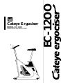
1
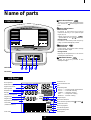
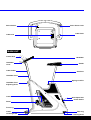
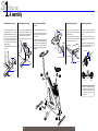
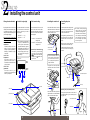
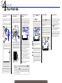
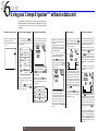
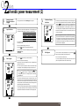
Cateye Ergociser
MODEL EC-1200
OPERATING INSTRUCTIONS
EC-1200
EC-12OO
R
How to Use This Manual
After you read the Starting up section
of this manual, assemble your Cateye
ErgociserTM and try it out . When you
get used to the machine and develop a
greater interest in it, please read the Operation section in preparation to trying
the machine's numerous functions. Turn
to the Reference section whenever the
need arises.
TABLE OF CONTENTS
1 Assembly --------------------------------------------------------------------------------- 6
2 Installing the control unit ------------------------------------------------------------- 8
3 How to adjust each part ------------------------------------------------------------- 10
4 Your first ride ------------------------------------------------------------------------- 12
5 The five programs of operation --------------------------------------------------- 14
6 Using your Cateye Ergociser without a data card -------------------------- 16
TM
1 Your strength level and training index ------------------------------------------ 20
2 Aerobic power measurement (Physical fitness test) -------------------------- 24
3 Automatic training ------------------------------------------------------------------- 28
4 Isopower (constant load) training ------------------------------------------------ 30
5 Manual training ----------------------------------------------------------------------- 32
6 Hill profile training ------------------------------------------------------------------- 34
7 How to make a data card ---------------------------------------------------------- 36
1 Handling the pulse (earlobe) sensor --------------------------------------------- 40
2 Troubleshooting ---------------------------------------------------------------------- 41
3 Handling/Warranty service --------------------------------------------------------- 42
4 Specifications -------------------------------------------------------------------------- 43
Name of parts
A Pitch Sound Button
CONTROL UNIT
Turns on or off the pitch sound. When the
pitch sound is on,
symbol appears on the
LCD.
EC-1200
B Value Adjust Button
Before exercise
Increases or decreases the blinking
numerical value by 1. (For pedal torque
(kg·m) by 0.1)
* When selecting the gender
+ ,
specifies MALE, and
– FEMALE)
During exercise
Increases or decreases pedal torque by
0.1kg· m, and the wattage by 5 watts.
CADENCE
HEART RATE
TRAINING COURSE
TIME
PEDAL TORQUE
WORK RATE
Hill Profile
Preference
PRF-1, PRF-2, PRF-3
PRF-2 the Cascades
TIME
PRF-1 the Apennino
C Mode Button
PRF-3 the Pyrenees
Before exercise
Used to select the program and to change
the item of data to input.
INSTRUCTIONS
1. Attach the pulse sensor.
2. Press
until desired program name flashes.
3. Press
to enter the program.
4. Press
5. Press
6. Press
to adjust blinking digits.
to let other digits blink. Repeat 4 & 5.
to start the program.
During exercise
Displays the elapsed time or the calorie
consumption alternatively.
VALUE ADJUST
MODE
D ADVANCE Button
ADVANCE
Makes the program proceed to the
subsequent stage.
SOUND ON/OFF
LCD Panel
A
B
C
D
Card Inlet
LCD Panel
Cadence Unit
Error Symbol
Maximum Oxygen Uptake
Upper Pulse Limit
MOU
PLL
ml/kg•min
E
Pulse Symbol
Elapsed Time
Weight
Calorie Consumption
Target Pulse
Target Load
Physical Work Capacity
kcal
kg lb
min:sec
TM
WT
EC
TPL
TLD
PWC
rpm
PFL
AGE
watt
bpm
TEST AUTO
HILL CONST
MANUAL
TTQ
PRF
kg•m
Physical Fitness Level
Age
Program Symbol
TEST ------- Aerobic power measurement
AUTO ----- Automatic training
CONST ---- Isopower training
HILL ------- Hill profile training
MANUAL - Manual training
Target Torque
Exercise Preference
w
kg•m
Load Scale
(Pedal Resistance)
WARM
COOL
Sex Distinction Symbol (Male)
Load Scale Value
Warm Up Symbol
Cool Down Symbol
Pitch Sound Symbol
Time Scale
TIME
2
Card Symbol
(Female)
ON
1 2 3 4 OFF
Select Switch
Pulse Sensor Jack
Cable Hook
Cable Inlet
MAIN UNIT
Control Unit
Handlebar
Handlebar
Lever
Saddle
Cable Holder
Seat Post
Handlebar Post
Spring Lock Pin
Handlebar Post
Adjusting Knob
Crank
AC Adapter Inlet
Power Switch
Pedal
EC-1200
Front Leg
Caster
Levelling Knob
Rear Leg
Levelling Knob
INTRODUCTION
Thank you very much for your purchase of the Model EC-l200 Cateye ErgociserTM. The
model EC-1200 is a new high-tech exerciser with a built-in computerized training system designed specifically to promote cardiovascular fitness and overall endurance, the
keystone of good health. With its endurance test program and four training programs,
the EC-1200 will help you to maintain or improve your physical strength in a fun and
pleasant way. We hope you will make good use of your Cateye ErgociserTM for years to
come.
Before using your new exerciser, please read this manual carefully. Then store it in a
safe place along with the warranty card.
FOR SAFE OPERATION
For safe use, always observe the following rules.
1. Before using the EC-1200, it is important to consult a medical specialist if you are
suffering from any of the following : heart disease (angina pectoris, myocardial infarction), hypertension, diabetes, respiratory disease (asthma, chronic bronchitis, pulmonary emphyusema, etc.), articular metamorphosis, rheumatism, gout, or other diseases and physical complaints. Pregnant women should also consult their doctor before commencing a training program.
2. If you are not used to regular physical activity, it may be dangerous to suddenly engage in strenuous activity. Increase your exercise level gradually.
3. If you feel sick or sense that something is wrong with your body during exercise, stop
immediately.
IMPORTANT SAFETY INSTRUCTIONS
Read all instructions before using this exerciser.
DANGER
To reduce the risk of electric shock:
1. Always unplug this AC adapter from the electrical outlet immediately after using and before cleaning.
WARNING
To reduce the risk of burns, fire, electric shock, or injury to persons:
1. An AC adapter appliance should never be left unattended when plugged in. Unplug from outlet when not in use,
and before putting on or taking of parts.
2. Close supervision is necessary when this exerciser is used by, on, or near children, invalids, or disabled persons.
3. Use this exerciser only for its intended use as described in this manual. Do not use attachments not recommended
by the manufacturer.
4. Never operate this exerciser if it has a damaged cord or plug, if it is not working properly, if it has been dropped
or damaged, or dropped into water. Return the exerciser to a service center for examination and repair.
5. Do not carry this exerciser by supply cord or use cord as a handle.
6. Keep the cord away from heated surface.
7. Never operate the exerciser with the air openings blocked. Keep the air openings free of lint, hair, and the like.
8. Never drop or insert any object into an opening.
9. Do not use outdoors.
10. Do not operate where aerosol (spray) products are being used or where oxygen is being administered.
11. To disconnect, turn all controls to the off position, then remove plug from outlet
This exerciser is intended for both household and commercial use.
This equipment has been certified to comply with the limits for a Class B computing device, pursuant to Subpart J of
Part 15 of FCC Rules. Only peripherals (computer input/output devices, terminals, printers, etc.) certified to comply
with the Class B limits may be attached to this computer. Operation with non-certified peripherals is likely to result
in interference to radio and TV reception.
SAVE THESE INSTRUCTIONS.
3
1
Assembly
2 Installing the control unit
3 How to adjust each part
4 Your first ride
5 The five programs of operation
6
Using your Cateye Ergociser™ without a data card
Make sure all components are included in a package.
ADV
MODE
SOUND
EC-
12
ON/OFF
Control Unit
Legs (2 pcs)
Saddle
Handlebar & Handlebar Post
Pedals (L,R)
AC adapter
ON
00
Main Body
OFF
R
O
P
EC
-1
2
O
O
E
r
se
ci
o
rg S
E ION
e RUCT
ey INST
at G
C RATIN
D
A
T
A
EC-12
00
C
A
R
D
Pulse Sensor
Data Card (10)
Start Card (1)
Sensor Clip
Tools
Operating Instructions
Warranty Card
Assembly
1. Attaching the front leg
2. Attaching the rear leg
3. Mounting the handlebar
post
• Remove the two screws from the respective leg pipes. The one with
casters should be used as front leg.
• Place the rear leg pipe under the
rear end of the main body, and adjust the position so that the screw
holes meet the fastening points.
• Remove the handlebar post knob.
• Place the front leg under the front
end of the main body with casters
facing forward, and adjust the position so that the screw holes meet the
fastening points.
• Fasten the leg with the two screws
securely.
ON
O FF
• Fasten the leg with the two screws
securely.
screw
handlebar post
• Insert the handlebar post into the
main body, with the post holes facing forward.
• Adjust the handlebar height so that
one of the post holes meets the post
knob screw hole, and fasten the post
knob securely. It will be easier to
screw in if you slightly lift the handlebar post.
4. Mounting the saddle
5. Attaching the pedals
• Pull the spring lock pin and lift up
the seat post to a proper height for
saddle mounting.
• Use the No.15 end of the spanner to
attach the pedals firmly to the
cranks.
• Mount the saddle on the seat post,
and use the wrench No.13 provided
to tighten both nuts firmly.
• The right and left pedals are different, so be sure to check for R and L
marks.
tighten
• Tighten the right pedal by turning
clockwise, and the left pedal by
turning counterclockwise.
wrench No.15
loosen
handlebar post knob
screw
wrench No.13
Rear
crank
seat post
leg pipe
Front
leg pipe
3
caster
4
Front
left (L)
right (R)
CAUTION: If the pedals are not
attached firmly enough to the
crank, they can cause an irritating noise. Be sure to attach
them firmly.
EC12
00
ON
OF
F
1
5
6
2
7
Installing the control unit
1. Strength evaluation table
2. Units for body weight
3. Pitch sound setting
4. Installing the control unit
5. Installing the pulse
sensor
• By using switches No.1 and 2 in the
aerobic power measurement (physical fitness test) program, you can
change the internal tables by which
your strength is judged.
• Use select switch No.3 on the back
of the control unit to choose kilograms or pounds as your unit of
body weight.
• Use the select switch No.4 on the
back of the control unit to determine the initial setting of the pitch
sound for Aerobic Power Measurement program.
• Insert the cable connector into the
cable inlet on the back of the control
unit, and cover up the connector
with the connector cover.
• Insert the pulse sensor plug into the
pulse sensor jack on the back of the
control unit, and hang the sensor
cable on the cable hook.
• When the Model EC-1200 Cateye
ErgociserTM leaves the factory, it is
set for American use.
1-ON 2-OFF
American use
Evaluation table by AHA Committee: "Exercise testing and
training of apparently healthy individuals, A handbook for physicians(1972)"
1-OFF 2-ON
European use
Evaluation table by Dr.
Åstrand:"The values from P. -O.
Åstrand, Work tests with the bicycle ergometer"
1-OFF 2-OFF
Japanese use
Evaluation table by Dr.
Ikegami:"Exercise prescriptions
in theory and practice"
NO.3-OFF -------- kg
NO.3-ON ---------- lb
CAUTION: When oxygen uptake
(VO2max) is estimated in the
aerobic power measurement
(physical fitness test) program,
body weight in kg is used. If you
mistakenly assume the unit for
body, the figure given for oxygen uptake will be wrong by a
wide margin.
select switch
• During training, use the sensor clip
to take up slack in the cable and
keep the cable from moving excessively.
No.4 ON - Pitch sound initial
setting is ON
No.4 OFF - Pitch sound initial
setting is OFF
• When you are not using the pulse
sensor, attach it to the sensor clip.
cable inlet
• Attach the cable clip to your clothes
to keep the cable from swinging
around.
cable connector
Remark: Even if the switch No.4
is set at OFF, you can activate
the pitch sound by pressing
the button on the control unit
to light up the symbol in the
LCD screen.
ON
CAUTION: Handle the pulse
sensor with care. The cable
could break if strongly pulled.
Pulse sensor lenses need periodic cleaning to remove sweat
and oil deposits from skin to
work efficiently. Wipe lenses
with soft dry cloth.
connector cover
CAUTION: Insert the cable connector until it is firmly locked.
The control unit will not function properly with a partial or
faulty connection.
pulse sensor jack
1 2 3 4
• Using the four screws provided,
mount the control unit on the handlebar post.
OFF
ADV
MODE
ON/OFF
SOUND
pulse sensor plug
pulse (earlobe) sensor
1
3
cable hook
screw
2
sensor clip
cable clip
cable inlet
cable hook
handlebar
post
Attaching the pulse (earlobe) sensor
• Insert the cable holder tip into the
upper smaller hole on the handlebar
post, to hold the cable in place.
pulse sensor jack
Firmly clip the pulse sensor to the center of
your either earlobe. If you are wearing an ear
ring, put it off.
pulse (earlobe) sensor
select switch
cable holder
cable
holder
8
smaller hole
9
How to adjust each part
1. Adjusting the saddle
height
2. Adjusting the handlebar
height
3. Adjusting the handlebar
angle
4. Adjusting the pedal belt
5. The levelling knobs
6. Adjusting all parts to fit
• Pulling on the spring lock pin will
enable you to move the seat post up
or down. When the saddle is at the
correct level for you, release the
knob and move the seat post
slightly.
• Decide the approximate height by
one of the 3 holes on the handlebar
post, then fix the final position by
adjusting the handlebar angle.
• When you turn the handlebar lever
clockwise (when mounted), the
handlebar is loosened. The lever
turns idle when pulled downward.
• The pedal belt length of the EC1200 can be adjusted according to
your shoes size.
• Ideally, you should only use your
exerciser on a hard, level floor.
• Make various height and angle adjustments so that your posture when
seated on the exerciser is like that
shown in the diagram below.
• Remove the handlebar post knob.
• Rotate the handlebar and hold it at
the desired angle.
• A spring inside the spring lock pin
will drive a pin into the nearest hole
in the seat post, locking it in that
position.
• The pitch of the seat post holes is 1"
(approx. 25mm).
seat post
• Hold the handlebar post where one
of the post holes meets the post
knob screw hole, and fasten the post
knob securely. It will be easier to
screw in if you slightly lift the handlebar post.
• If the exerciser tilts or wobbles during use, turn one or more levelling
knobs until a stable position is maintained.
• Turn the handlebar lever counterclockwise to fix the handlebar angle.
handlebar lever
levelling knob
ADV
MODE
SOUND
• The pitch of the handlebar post hole
is 3" (approx. 76mm).
ON/OFF
handlebar post
• For proper handlebar height and
angle, you should be leaning slightly
forward when holding the handlebar.
• When you move the exerciser, lift
the saddle and roll the exerciser on
its casters.
handlebar
lower
pitch 1"
(approx. 25mm)
• For proper saddle height, your
knees should be slightly bent when
the pedal is at its lowermost position.
higher
3
Pull
tighten
loosen
tighten
idle
1
2
spring lock pin
loosen
CAUTION: Do not attempt to
adjust the saddle height while
you are mounted.
handlebar post knob
CAUTION: Make sure to grasp
the handlebar post firmly when
you loosen the handlebar post
knob, otherwise it could drop
suddenly and damage the unit.
EC-1200
EC-
12
ON
00
OF
F
4
5
10
11
Your first ride
1. Turn on power and attach
pulse sensor
2. Insert the start card (red
card provided)
3. Checking the screen
display
4. Press the DV
start
• Insert the AC adaptor into the AC
adapter inlet at the rear of the exerciser.
• Find the red card (start card) in the
packaging of the exerciser. Insert
this card into the appropriate slot
(card inlet) as shown in the diagram
below.
• The display that appears on the
screen should be as described below. If this display does not appear,
pull the card out and slowly insert it
again. The numbers in the display
represent training conditions.
• Press the DV button.
• Insert the plug of the AC adaptor
into any household AC outlet (110120V).
• A display like that in the diagram
below will appear on the screen.
The numbers on this screen represent your own present condition,
and they will change frequently.
1
2
AC adapter inlet
button to
PLL
2
1
AGE
rpm
ON
TM
HILL 4
O FF
3
MODE
TM
min:sec
3
HILL
ADV
ON/OFF
SOUND
min:sec
5
PRF
4
6
power switch
watt
5
kg•m
kg•m
6
5. Calorie display
6. When you finish
• Pushing the MO button gives you
the option of viewing a calorie consumption display (calorie consumed
from the beginning of the present
training session until now) instead
of elapsed time.
• When 16 minutes have elapsed, a
buzzer will sound and the training
session will automatically stop.
• Now you are on the exerciser for
your first ride. As you train, pedal
resistance will change, energy expenditure will change, and your
pulse rate will also change. The
Model EC-1200 lets you keep track
of all this information while you
train.
• The liquid crystal display on the
screen will return to initial display,
"AUTO" alone flashing.
kg•m
rpm
start card
card inlet
TIME
1 Age is shown by the figure "50"
plug
• Turn on power switch. The control
unit should make a beep sound and
"AUTO" should appear on the
screen.
TIME
CAUTION: Use only the red card
at this stage. It is a sample card
with the exercise data already
registered in it. The unit will not
work with the black cards since
they do not contain any data
yet.
AUTO
2 "150" is the upper-limit pulse rate
set by the machine (200 - age). If
this pulse rate is exceeded during
training, an alarm will sound and
the pedal resistance will become to
minimum (0.5kg·m).
3 Exercise time is shown by "16:00",
which means 16 minutes.
4 "HILL" which is short for "hill
profile training" shows the type of
training to be engaged in.
Insert this
direction
TIME
start card
• Attach the pulse sensor to your earlobe. When it is cold,rub your earlobe to facilitate blood circulation
before attaching the pulse sensor.
CAUTION: Do not use any AC
adaptor other than the one supplied with the Model EC-1200.
5 "1" indicates the shape of the hill
to be climbed. "1" is the gentlest
slope.
6 Changes of pedal resistance are
shown on the graph.
1 Heartbeats per minute.
2 Pedal revolutions per minute.
kcal
kg•m
watt
3 Elapsed time since start of training
session.
kg•m
4 Energy expenditure, expressed in
watts. The higher the number, the
more energy you are expending.
TIME
5 Pedal resistance. The higher the
number, the harder it is to pedal.
6 As time goes on, the blinking row
in the graphic part will shift one by
one toward the right hand. According to the position of the
blinking row you can find how far
you have progressed in the current
session.
Remark :
You may change data at any time. The ++ and
- – buttons will raise or lower any of the numbers discussed
above. Press the MO button to move to the next number,
which will flash on and off when it is eligible for changing. Now,
however, the goal is to get you acquainted with Model EC-1200,
so if you change any of the numeral values, please return them
to their original setting.
12
HILL
EC
13
• You may stop exercise program at
any time during workout by pressing A
button twice.
• The Model EC-1200 Cateye
ErgociserTM function that we have
explained up to this point is only the
beginning. Let us move on to an explanation of other functions.
The five programs of operation
1. Aerobic power
measurement
(physical fitness test)
2. Automatic training
(training at a constant pulse
rate)
3. Isopower training
(training at a constant
energy expenditure)
4. Manual training
(training at a constant pedal
resistance)
5. Hill profile training
(training by cycling up
mountains)
• Over a period of 10 minutes, you
will encounter three different levels
of pedal resistance. Your pulse will
change in response to the different
levels of resistance, and this change
in pulse will be used to calculate
your overall fitness level, also expressed is MOU (VO2max). MOU
stands for maximum oxgen uptake.
The higher your overall fitness
level, the greater your endurance.
• You set the pulse rate at which you
want to exercise and the Model EC1200 automatically adjusts pedal resistance to maintain that pulse rate.
This is an ideal basic form of aerobic
training.
• The figure for energy expenditure
that is shown on the screen of the
Model EC-1200 is calculated from
pedal resistance (kg·m) and cadence
(rpm).
• You choose the pedal resistance
(torque:kg·m), and it stays constant.
This is the most traditional way in
which stationary bicycles have been
used.
• Pedal resistance changes over time
to simulate the effect of cycling in
the mountains. All changes in pedal
resistance are shown on the screen.
• In isopower training, you set the desired energy expenditure in watts.
The Model EC-1200 takes into account your cadence (rpm) and adjusts pedal resistance (kg·m) automatically so that energy expenditure in watts remains constant.
Torque setting range:
0.5~4.0 kg·m
Minimum graduation: 0.1 kg·m
• Your MOU value is compared with
the MOU values of other people
who are the same age and sex as
you. You are given a physical
strength number from 1 to 5 depending on how you rank.
• As you repeat the exercise at a certain pulse rate and make progress in
your fitness level, you will be able to
create a greater work intensity under the same pulse rate. Further,
you will be able to try exercising at a
higher target pulse rate.
PULSE RATE
• These results should give you a
good idea of your own fitness level
and help you to determine what sort
of training program will be the most
effective for you. For information
on how to choose a training program, refer to "Your strength level
and training index" on page 20~23
in the Operation section on this
booklet.
• This type of training is also called
constant load, and is often used in
cardio-vascular rehabilitation.
Control range:
cadence: 40~100 rpm
wattage: 25~200 watts
NOTE: If you set your target
wattage as under 50 watts, control limit of cadence (rpm) becomes under 100 rpm.
the Apennines
PRF-2
the Cascades
PRF-3
the Pyrenees
• There are three types of mountain
profile as follows:
PRF-1 the Apennines (Italy)
PRF-2 the Cascades (U.S.A.)
PRF-3 the Pyrenees
(France, Spain)
TORQUE
• The mountain profiles from 1 to 3
are arranged in order of ascending
difficulty. Do not strain yourself,
but rather enjoy the form of each
mountain.
• The initial setting of the exercise
time is 16 minutes. You can either
increase or decrease the training
time, in which case the over all hill
pattern will not be changed, but
shortened or stretched horizontally
in proportion with the designated
time.
WORK RATE
TORQUE
14
PRF-1
15
Using your Cateye ErgociserTM without a data card
The red card you used on your first ride contains data used in
selecting different types of training. Even without this card, you
can use buttons on the control unit to run through the same
operations.
1. Switch on power supply
2. Select a training program
3. Input training conditions
• Plug in the AC adaptor and connect
to the exerciser. Switch on.
• With each press of the MO button, the flashing indicator moves
from one mode to the next in the
following order.
• The screen display will change to
the one shown in the diagram here,
with the number "40" flashing.
• The screen display will be a flashing
"AUTO".
PLL
AGE
AUTO
:Automatic training
AUTO
TM
REMARK: Conditions will
change according to the training
program.
Upper limit pulse rate is automatically determined by your
age, so there is no need to set
this number yourself.
4. Start training
5. At the end of training
• When you have finished setting
training conditions, push the AD
button and start pedaling. The
screen display will change as shown
below, as time goes on.
• A buzzer will sound when the training time you have set is finished. If
you wish, you can continue training
even after this buzzer sounds.
rpm
min:sec
AUTO
CONST
:Isopower training
• Let's try changing the displayed target pulse rate from 120 to 115.
TPL
bpm
MANUAL :Manual training
TIME
HILL
:Hill profile training
TIME
TEST
Aerobic power
: measurement
• On your first ride, you tried hill profile training. This time choose
"AUTO".
• Push the MO button until
"AUTO" flashes, then push ADV
to lock in your choice.
• You can raise or lower the flashing
number by pressing either the
+++
or – button. When +
–button is held down, the number
changes rapidly.
• With each press of the MO button,
the flashing indicator moves from
one number to the next in the following order.
• Press the MO button until "120"
is flashing. You want to reduce the
number by five, so press the – button five times. Has the number
changed to "115"?
AUTO
TM
min:sec
kg•m
watt
kg•m
WARM
TIME
PLL
AGE
AUTO
TM
min:sec
TPL
bpm
AGE
• The automatic training, isopower
training and manual training programs all have a warm-up function.
Pedal resistance increases slowly
until you reach your target pulse
rate (Automatic training) or for the
first three minutes (all others).
While the warm-up function is operating, a WARM
WA symbol will remain
on the screen.
TIME
PLL
(upper limit pulse rate )
TM
(training time)
TPL
(target pulse rate)
• A card is a tool for setting program
choice and training conditions. A
card saves you the trouble of setting
the same training conditions every
time you use the exerciser. For instructions on how to make a card,
please refer to page 36, "How to
make a data card" in the Operation
section.
• By pushing the MO button, you
can switch the display from elapsed
time (TM min:sec) to calorie consumption (EC Kcal).
• Whenever you want to stop training, before or after the buzzer
sounds, push the AD button once.
• The coo
COOL symbol appears on the
screen and the pedal resistance
drops to the minimum of 0.5 kg·m.
This is the cooling down function,
which lasts for a maximum of 5 minutes.
• At this stage review your workout
data such as time and calorie consumption.
rpm
AUTO
TM
min:sec
kg•m
watt
kg•m
COOL
TIME
• Press AD button once again and
the program comes to the ultimate
end and the display turns to the initial state. (If you stay in the cool
down phase for the full five minutes,
the program ends automatically
with no need to press the AD button.)
• You should now understand how to
use the Model EC-1200 Cateye ErgociserTM. Once you get used to the
exerciser, you will probably want to
refer to the Operation section for
more detailed information on functions, etc.
16
17
1 Your strength level and training index
2 Aerobic power measurement
(Physical fitness test)
3 Auto matic training
4 Isopower (constant load) training
5 Manual training
6 Hill profile training
7 How to make a data card
Your strength level and training index (1)
Purpose of Exercise
Glossary of Terms
• Have you ever been out of breath after climbing a flight of stairs or
after a brisk walk? When we are walking, running and even sleeping, our body is taking in oxygen and generating energy. Oxygen
taken in by the lungs is sent to the entire body via the circulatory
system. If the function of the circulatory system , i.e. aerobic power,
is insufficient, we may experience being "out of breath" or experience yet other physical problems.
• Maximum Heart Rate
The heart rate increases according to the intensity of exercise, there
is however a limit. The maximum heart rate that a person can sustain
is called the "maximum heart rate". Generally the heart rate declines as we get older, this differs however between individuals, and
is largely due to how much one exercises.
• Difference Between the Heart Rate and Pulse Rate
The heart rate is the rate of the heart beat per minute measured by
an electrocardiograph. On the other hand, the pulse rate is measured as follows.
• We therefore perform "sports for the heart" (aerobic exercise),
which causes the heart to work a little more a few times a week, thus
increasing the oxygen supply to the body via the circulatory system.
The purpose of exercise with the Ergociser is to improve both your
physical strength and the functioning of the circulatory system: to
improve our aerobic power.
1)By palpating an artery near the skin surface, such as the carotid
artery, measure the pulse count of a blood vessel.
2)Transmit a sensor light to an earlobe or finger tip, and measure the
pulse count via the subtle changes of the sensor light transmission
caused by the heart beat.
Exercise Plan
• To effectively perform "sports for the heart" and to improve your
aerobic power, it is necessary to exercise according to your age and
physical fitness. If exercise exceeds your physical fitness level you
only injure your body. On the other hand, if the exercise is insufficient, a positive effect cannot be expected.
Although the measurement principle and method are different, both
the heart and pulse rates have the same value per minute, and are
therefore regarded as synonymous.
Since earlobes move very little during exercise and are not influenced very much by physical movement, it is appropriate to use an
earlobe to measure the pulse rate during exercise. The Ergociser
EC-1200 therefore measures the pulse rate by detecting changes in
the circulation of the earlobe.
• The Ergociser EC-1200 has 5 types of computer-controlled programs. One program is the "Aerobic Power Measurement Program". This test program evaluates your physical fitness level, while
the other programs are for actual exercise.
• Pulse Limit
As a standard maximum heart rate, "220–Age", "204–0.69 x Age",
etc. are used. With the Ergociser EC-1200, a somewhat lower value
is used: "200–Age". This pulse limit allows a person to safely exercise.
• The "Aerobic Power Measurement Program" evaluates your physical fitness level so that you can determine the training index and
begin exercise based on the measured result. After exercising for a
while (about 3 months),you become aware of the effect on your
body. Test your physical fitness level again and gradually set a
higher training index, thus maintaining and improving your physical
fitness level. A special feature of the Ergociser EC-1200 is that it
combines testing with exercise.
• Target Pulse Rate
The pulse rate to maintain during exercise as a target is called the
"target pulse rate". In the "Auto training" program, this pulse rate is
automatically maintained. However, even with other programs, always be conscious of your target pulse rate during exercise. Refer to
the illustration on the left.
Aerobic Power Measurement
Exercise Planning
Exercise
Exercise Frequency and Time
• At least 15 minutes are required for one exercise period, however if
possible a 20 ~ 30 minute period is even better.
• To maintain your present condition, exercise at lease twice a week,
3 times a week would improve your condition even more. The ideal
however is to exercise every day or 5 ~ 6 times a week.
20
NOTE : You could also letermine your
target pulse rate more simply by deducting your age from a certain figure.
For a beginner, for instance, it is recommendable to start with [160–age
(approx. 30~50% depending on your
age)], and gradually proceed to higher
level such as [180–age (approx.
50~70%)]. It would be ideal to aim at
[190–age] eventually.
• Exercise Level Based on the Pulse Rate
The pulse rate increases according to the intensity of the exercise. In
other words, the pulse rate during exercise is a barometer for the
exercise level. The exercise level can be determined in percentages
by the following formula.
Exercise Level (%) =
Pulse rate during exercise – Pulse rate at rest
x 100
Maximum heart rate – Pulse rate at rest
Therefore, if you want to discern the target of the exercise level
from the pulse rate (target pulse rate), you can calculate as follows.
Target pulse rate = (maximum heart rate – pulse rate at rest)
exercise level (%)
x
+ pulse rate at rest
100
20
Your strength level and training index (2)
Physical Fitness Level
and Training Index
1. Automatic Training
The "Aerobic power measurement" program evaluates your physical
fitness level according to 5 levels, and it also evaluates your maximum
oxygen uptake with an estimated value. Based on the result, you can
choose your own training level (program type and exercise intensity)
from the following index.
3. Manual Training
• In this program, the exercise intensity is set by the pedal resistance
(torque: kg.m.).
• Exercise for at least a 15 minute period. If possible a 20 ~ 30 minute
period is even better. Since the warm up takes 3 minutes, set your
exercise time to "actual exercise time + 3 minutes".
• In this program, the exercise intensity is set by the target pulse rate
(beats per minute: bpm). Select your target pulse rate from the following table, based on your age and physical fitness level (PFL)
from 1 to 5.
• If the target you select is difficult, reduce the target pulse rate by 10
bpm. You need not work hard from the beginning, continuing is
most important.
• This table is arranged so that even people who have not exercised so
much can benefit. The targets in this table may be too easy for
people who exercise often. If you have confidence, increase your
target in 10 bpm units, referring to the target zone in the illustration
on page 21.
• Exercise for at least a 15 minute period. If possible a 20 ~ 30 minute
period is even better.
• If overweight control (calorie combustion) is the purpose of the exercise, set the target pulse rate lower so that you can easily exercise
even while watching TV, but extend your exercise time longer, exceeding 30 minutes.
PFL
20~30s
40~50s
over 60s
1
2~3
4~5
110 bpm
120 bpm
130 bpm
100 bpm
110 bpm
120 bpm
95 bpm
105 bpm
115 bpm
2. Isopower Training
• In this program the exercise intensity is set by the work rate: wattage. Select the target wattage from the table shown below, according to your PWCmax. value provided by the Aerobic Power Measurement.
• If the selected wattage proves too hard for you, try again at the level
10 watts lower. When it becomes easy enough, raise the target by 10
watts.
• Exercise for at least a 15 minute period. If possible a 20 ~ 30 minute
period is even better. Since warm up takes 3 minutes, set your actual
exercise time to "actual exercise time + 3 minutes".
PWCmax
100 watt
120 watt
140 watt
160 watt
180 watt
200 watt
22
Terget Wattage
PWCmax
Terget Wattage
40 watt
50 watt
55 watt
65 watt
70 watt
80 watt
220 watt
240 watt
260 watt
300 watt
350 watt
400 watt
90 watt
95 watt
105 watt
120 watt
140 watt
160 watt
Pedal Torque(kg·m)
PWCmax
120 watt
140 watt
160 watt
180 watt
200 watt
220 watt
240 watt
260 watt
280 watt
300 watt
350 watt
400 watt
50rpm
70rpm
90rpm
0.9
1.1
1.2
1.4
1.6
1.7
1.9
2.0
2.1
2.3
2.7
3.1
0.7
0.8
0.9
1.0
1.1
1.2
1.3
1.5
1.6
1.7
1.9
2.2
0.5
0.6
0.7
0.8
0.9
1.0
1.1
1.1
1.2
1.3
1.5
1.7
4. Hill Profile Training
• Merely select one of the 3 patterns of this program. Try different
hill profiles (shape of the mountain) in a range where you don't
feel too much difficulty. The exercise intensity can also be adjusted
by pedaling slower or faster depending on the changes of pedal
resistance.
• First, choose the most suitable preference (PRF) according to your
PWCmax value, from the table shown below.
• The exercise time is initially set as 16 minutes, but you can revise it
down to minimum 3 minutes or up to 99 minutes.
PWCmax
140 watt
195 watt
240 watt
Exercise Pattern(PRF)
1
2
3
Calorise Consumption
75 Kcal
110 Kcal
120 Kcal
• The calorie consumption provided above is based on the cadence
of 60 rpm and the exercise time of 16 minutes. The calorie expenditure will vary in proportion with the pedal cadence and the exercise time.
22
Aerobic power measurement (1)
Select the Aerobic
Power Measurement
Program
1
• For program selection see the Starting up section page 16.
Test Result Display,
Cool Down
4
MOU
ml/kg·min
PFL
2
• Input your age, pulse limit, weight and sex. The initial display prior
to input is as in the drawing. The numeric for age is blinking.
Input Conditions
Initial
Age
Pulse Limit
Weight
Sex
PLL
AGE
TEST
lb
WT
Value
40
160 bpm
130 lb
Male
kcal
TEST
• Review and record the test result on a memo at this point, before
the screen turns blank.
EC
Setting Range
10~ 99
80~ 180 bpm
• The buzzer sounds at ten minutes and the test result is displayed on
the LCD. The program then enters the 5 minutes cool down phase
and the COOL
CO symbol shows up, while the LCD keeps displaying
the test result, along with the calories consumed during the test. If
you keep pedaling during the cool down period, only the EC (Calorie Consumption) will be updated, while all other data remain fixed.
watt
PWC
kg·m
COOL
TIME
• The pitch sound to adjust your cadence at 60 rpm (rings every half
second) is set "ON".
Note: If the upper pulse limit alarm is activated and the workload
drops to the minimum within 4 minutes after starting pedaling,
the test result is not displayed. But if the upper pulse limit is
activated after 4 minutes of pedaling, your aerobic power is estimated based on the progress up to that point only, and the approximate result is displayed.
• There is no graphic display yet in the LCD.
• Press the MO button to change the blinking numeric.
• You can increase or decrease the blinking numeric by pressing the
+ + - – button.
TIME
5
End Program
• If the 5 minute cool down phase elapses or if you press the AD
button, the buzzer sounds and the program ends.
• The LCD returns to the initial screen.
3
• Press the AD button after you set the conditions.
Start Program
• The LCD changes as in the drawing.
rpm
min:sec
kg·m
watt
kg·m
TIME
rpm
TEST
TM
• Wait calmly for one minute. Meantime "READY is displayed in the
graphic part of the LCD.
• After one minute has elapsed, the buzzer sounds and the pitch
sound begins. Then start pedaling according to the pitch sound.
TEST
TM
• If you are completely finishing the exercise, be sure to turn the
power off by the switch at the rear of the main body.
Note: You can cancel the pitch sound by pressing the sou button. If the
symbol is on the LCD, the pitch sound is ON, if
not displayed, pitch is OFF. Pressing the pitch sound button
toggles ON/OFF.
• The initial workload (pedal torque) is indicated in dot(s) in the
graphic part of the LCD. One dot along the horizontal axis indicates
30 seconds, and one along the vertical axis 0.5 kg·m. At every 30
seconds, the row of dots will increase by one towards the right of the
graphic display, with the last dots blinking.
min:sec
kg·m
watt
• At the 4th and 7th minutes the pedal torque will increase depending
on your pulse rate at that time. The increased torque of 2nd and 3rd
stages will be indicated in dots time after time in the graphic part.
kg·m
TIME
24
24
Aerobic power measurement (2)
Physical Fitness Level
(PFL)
• There are five physical fitness levels: 1 ~ 5. These levels are relative
evaluations that compare your maximum oxygen uptake (MOU), estimated by the aerobic power measurement program, with the values of
other people of the same age and sex (Physical Fitness Level Test
Table).
• Ergociser EC-1200 stores the following physical fitness level test table,
which can be selected by the selector switch on the back panel of the
control unit. (See page 8)
Physical Fitness Level Test Table by
Maximum Oxygen Uptake (MOU)
5: Excellent
4: Good
3: Average
2: Fair
1: Poor
[American Males]
(ml/kg min)
60
M
O
U
54
54
48
48
42
42
36
36
30
30
24
24
18
18
12
12
6
6
0
(Age) 20s
Maximum Oxygen Uptake
(MOU)
30s
40s
50s
[American Females]
(ml/kg min)
60
60s
Test Protocol
• In the "Aerobic power measurement" program of the EC-1200, the
workload (pedal resistance:torque) for the subsequent stage is determined depending on your pulse rate at the previous stage. The
workload (pedal resistance:torque) will be increased along one of
the routes illustrated below, depending on your pulse rate ™during
the program.
• The pulse rates specified below represent the protocol for a person
of 20 years. For the people over 20, the borderline of pulse rate will
be adjusted by the age adjustment coefficient (K), which is obtained
by the following formula:
204–0.69 x Age
K =
204–0.69 x 20
• For people over 60 years, the coefficient (K) is calculated as 60.
Male
Pulse≥135
Pulse≥110
0
(Age) 20s
30s
40s
50s
120≤Pulse<135
Pulse<120
60s
Pulse≥135
• MOU is widely used as an index for total physical endurance. MOU
indicates the amount of oxygen one can intake at the limit of their
physical work capacity. In the Ergociser EC-1200, MOU is calculated
based on the maximum physical work capacity (PWC max.) explained
below, assuming that
1.0 kg
90≤Pulse<110
Pulse<90
• PWC max. safely estimates how much exercise is possible at the limit of
physical work capacity, that is, at maximum heart rate without performing actual exercise.
0.5 kg
Pulse≥115
120≤Pulse<135
0.8 kg
Pulse≥123
Pulse<123
95≤Pulse<115
1.0 kg
Pulse≥123
Pulse<123
(bpm)
180
Maximum Heart Rate
Pulse<95
1.5 kg
Pulse≥123
Pulse<123
Measurement
1.8 kg
2.2 kg
2.2 kg
2.6 kg
3.0 kg
3.0 kg
3.3 kg
3.5 kg
1.1 kg
1.4 kg
1.5 kg
1.8 kg
1.8 kg
2.5 kg
Estimate
80
Heart Rate
25
50
Work Rate
26
2.5 kg
Pulse<120
Female
120
120≤Pulse<135
Pulse≥135
• In the Ergociser EC-1200 "Aerobic power measurement" program the
weight of the pedals are changed at 3 levels, and the pulse rate at the
end point of each level is measured. Based on the result, the relationship between the work rate (wattage) and the pulse rate is analyzed by
linear regression. Extend the regression line until reaching the maximum heart rate (=204–0.69 x age) which is estimated by age. The work
rate (wattage) of this point becomes the maximum physical work capacity.
140
1.8 kg
Pulse<120
1 litre of oxygen corresponds to 5.0 Kcal, and
the human efficiency rate for a bicycle exercise is 23%
Maximum Physical Work
Capacity (PWC max.)
1.2 kg
1.5 kg
75
100
125
150 (watt)
Remark: The load change for males over 50 years of age is the
same as for females.
When the age is less than 20, the load changes as if the age were
20.
Maximum Physical Work Capacity
26
Automatic training
1
Select the Automatic
Training Program
• For program selection see the Starting up section page 16.
5
Exercise Maintaining the
Target Pulse Rate
rpm
2
• Input age, pulse limit, exercise time and the target pulse rate. The
initial display before input is as in the drawing, with the numeric for
age blinking.
Input Conditions
Age
Pulse Limit
Exercise Time
Target Pulse Rate
PLL
AGE
AUTO
TM
min:sec
Initial Value
40
160 bpm
20 min
120 bpm
AUTO
TM
min:sec
Setting Range
10~ 99
80~ 200 bpm
0~ 99 min
60~ 180 bpm
kg·m
Remark 1: You can increase or decrease the pedal resistance by
pressing the + - – buttons.
Remark 2: The graphic part can display the torque pattern for 16
minutes at maximum, except in Hill Profile program. If you set
a longer exercise time, the graphic part becomes full at 16 minutes, then at every additional 30 seconds the torque pattern of
the latest 16 minutes will be updated on the screen.
• The pitch sound to adjust your cadence at 60 rpm (rings every half
second) is set "OFF".
bpm
Note: When the pulse rate is "0" (when the earlobe sensor is removed) or when the pedal cadence is "0" (when not exercising)
the pedal resistance does not change.
kg·m
watt
TIME
TPL
• After the WA
WARM symbol has gone out, during exercise every time
the pulse rate digresses ± 3 beats/min from the target, the load
changes 0.1 kg·m, keeping your pulse rate close to the target pulse
rate.
• There is no graphic display yet in the LCD.
• Press the MO button to change the blinking numeric. You can
increase or decrease the blinking numeric by pressing the
++
---+
– buttons.
TIME
6
Finish Exercise
Cool Down
rpm
3
• Press the AD
tions.
Start Program
button to start the program after you set the condiAUTO
TM
min:sec
kg·m
watt
4
Start Warm Up
kg·m
• The LCD changes as in the drawing.
• The buzzer sounds at the specified time. If you press the AD button, the program enters a 5 minute cool down phase and the COOL
COO
symbol lights up, then the pedal resistance becomes the minimum of
0.5 kg·m.
Note: Even if the buzzer sounds the program does not enter the
cool down phase unless you press the AD button.
• The LCD still displays the contents during exercise.
• Review your workout data such as time and calorie consumption
displayed, using the MO button.
COOL
rpm
AUTO
TM
min:sec
kg·m
watt
kg·m
WARM
• The initial workload (pedal torque) is indicated in dot(s) in the
graphic part of the LCD. One dot along the horizontal axis indicates
30 seconds, and one along the vertical axis 0.5 kg·m. At every 30
seconds, the row of dots will increase by one towards the right of the
graphic display, with the last dots blinking.
• The pedal resistance increases gradually, so that the pulse rate
comes closer to the target pulse rate.
WARM symbol remains until your pulse rate gets close to the
• The WA
target pulse rate.
TIME
7
End Program
• If the 5 minute cool down phase has elapsed or if you press the
AD
button, the buzzer sounds and the program ends. The LCD
returns to the initial screen.
• If you are completely finishing the exercise, be sure to switch off the
main body.
TIME
28
28
Isopower (constant load) training
1
Select the Isopower
Training Program
• For program selection see the Starting Up section page 16.
5
Exercise at Constant
Wattage
• After the WA
WARM symbol goes out, the pedal resistance (torque
kg·m) increases or decreases according to the pedal cadence. During exercise the pedal resistance (torque: kg·m) changes in 0.1 kg·m
units to maintain the set value for wattage.
rpm
2
Input Conditions
• Input age, pulse limit, exercise time and set wattage.The initial display prior to input is as in the drawing. The numeric for age is blinking.
Initial Value
Age
PLL
AGE
TM
min:sec
TLD
Pulse Limit
CONST
40
TM
min:sec
Setting Range
CONST
kg·m
watt
10~ 99
160 bpm
80~ 200 bpm
Exercise Time
20 min
0~ 99 min
Set Wattage
60 watts
kg·m
25~ 200 watts
• The pitch sound to adjust your cadence at 60 rpm (rings every half
second) is set "OFF".
• Press the MO button to change the blinking numeric.
You can increase or decrease the blinking numeric by pressing the
+-+
– buttons.
3
• Press the AD button to start the program after you set the conditions.
Start Program
6
Finish Exercise
Cool Down
• The buzzer sounds at the specified time.
rpm
4
Start Warm Up
• The LCD changes as in the drawing.
rpm
TM
min:sec
TM
CONST
kg·m
watt
kg·m
WARM
TIME
min:sec
• The initial workload (pedal torque) is indicated in dot(s) in the
graphic part of the LCD. One dot along the horizontal axis indicates
30 seconds, and one along the vertical axis 0.5 kg·m. At every 30
seconds, the row of dots will increase by one towards the right of the
graphic display, with the last dots blinking.
Remark: If you first press the OD button, and holding it down
press the AD button to start the program, instead of just
pressing the AD button, you can skip the warm up phase and
start the exercise at the preset wattage from the scratch.
30
CONST
kg·m
watt
kg·m
• If you press the A button, the program enters a 5 minute cool
down phase and the COOL
CO symbol lights up. Then the pedal resistance becomes the minimum 0.5 kg·m.
Note: Even if the buzzer sounds, the program does not enter the
cool down phase unless you press the AD button.
• The LCD still displays the contents during exercise.
• Review your workout data such as time and calorie consumption
displayed, using the MO button.
COOL
• During the 3 minute warm up, after starting exercise, the pedal resistance gradually increases and the WARM
WA symbol is shown.
NOTE: During the warm up, the pedal resistance is increased so
as to reach the set wattage in 3 minutes provided you pedal at 50
rpm. If you pedal faster than 50 rpm and reach the set wattage
earlier than 3 minutes, the warm up is finished at that moment.
Remark 1: In this program the target wattage can be revised during the exercise by 5 watts with each press of the ++
– buttons. In such case the revised target wattage is displayed for
2 seconds in place of the current wattage.
Remark 2: The graphic part can display the torque pattern for 16
minutes at maximum, except in Hill Profile program. If you set
a longer exercise time, the graphic part becomes full at 16 minutes, then at every additional 30 seconds the torque pattern of
the latest 16 minutes will be updated on the screen.
TIME
watt
TIME
Note: For calculation purposes, pedal cadence under 40 rpm is
regarded as 40 rpm, and pedal cadence over 100 rpm is regarded
as 100 rpm.
TIME
7
End Program
• If 5 minutes of cool down have elapsed or if you press the AD
button, the buzzer sounds and the program ends. The LCD returns
to the initial screen.
• If you are completely finishing the exercise, be sure to switch off the
unit.
30
Manual training
1
Select the Manual
Training Program
• For program selection see the Starting up section page 16.
5
Exercise
• Exercise with the set pedal resistance (torque, kg·m).
rpm
2
Input Conditions
Age
Pulse Limit
Exercise Time
Set Torque Value
PLL
AGE
TM
min:sec
TM
• Input age, pulse limit, exercise time, and the setting torque value.
The initial display prior to input is as in the drawing. The numeric
for age is blinking.
MANUAL
TTQ
Initial Value
40
160 bpm
20 min
1.0 kg·m
min:sec
MANUAL
kg·m
watt
Setting Range
10 ~ 99
80 ~ 200 bpm
0 ~ 99 min
0.5 ~ 4.0 kg·m
kg·m
Note: In this program, you can increase or decrease the pedal
resistance by pressing the +
+ - – buttons.
Remark: The graphic part can display the torque pattern for 16
minutes at maximum, except in Hill Profile program. If you
set a longer exercise time, the graphic part becomes full at 16
minutes, then at every additional 30 seconds the torque pattern of the latest 16 minutes will be updated on the screen.
TIME
kg·m
• The pitch sound to adjust your cadence at 60 rpm (rings every half
second) is set "OFF".
• Press the MO button to change the blinking numeric.
• You can increase or decrease the blinking numeric by pressing the
++
– buttons.
TIME
6
Finish Exercise Cool
Down
rpm
TM
min:sec
3
• Press the AD button to start the program after you set the conditions.
Start Program
MANUAL
• The buzzer sounds at the specified time.
• If you press the AD button, the program enters a 5 minute cool
down phase and the COOL
CO symbol lights up, then the pedal resistance becomes the minimum 0.5 kg·m.
Note: Even if the buzzer sounds, the program does not enter the
cool down phase unless you press the A button.
kg·m
watt
• The LCD still displays the contents during exercise.
kg·m
COOL
4
TIME
Start Warm Up
• The LCD changes as in the drawing.
rpm
TM
min:sec
MANUAL
kg·m
watt
kg·m
WARM
TIME
• The initial workload (pedal torque) is indicated in dot(s) in the
graphic part of the LCD. One dot along the horizontal axis indicates
30 seconds, and one along the vertical axis 0.5 kg·m. At every 30
seconds, the row of dots will increase by one towards the right of the
graphic display, with the last dots blinking.
• After starting exercise, during the 3 minute warm up, the pedal resistance gradually increases and the WARM
WA symbol is shown.
7
End Program
• If the 5 minute cool down phase elapses or if you press the
button, the buzzer sounds, the program ends.
• The LCD returns to the initial screen.
Note: During warm up the pedal resistance increases so that the
set torque value is reached in 3 minutes. If you have increased
the torque value to more than the set torque value by pressing
the +
+– buttons, warm up ends at that point.
Remark: If you first press the MO button, and holding it down
press the AD button to start the program, instead of just
pressing the AD button, you can skip the warm up phase and
start the exercise at the preset pedal torque from the scratch.
32
32
AD
Hill profile training
1
Select the Hill Profile
Training Program
• For program selection see the Starting up section page 16.
5
End Program
• The buzzer sounds at the specified time and the program completely ends. Review the calorie consumption using the MO
button when you get close to the specified time.
rpm
2
Input Conditions
• Input pulse limit, exercise time, and the exercise pattern. The initial
display prior to input is as in the drawing. The numeric for age is
blinking.
Age
Pulse Limit
Exercise Time
Exercise pattern
PLL
AGE
TM
HILL
min:sec
Initial Value
40
160 bpm
16 min
3
Setting Range
10 ~ 99
80 ~ 200 bpm
3 ~ 99 min
1~ 3
TM
Note 1: There is no cool down phase if you end the "Hill profile
training" program when it has reached the end of the exercise
time.
HILL
min:sec
kg·m
watt
• The LCD returns to the initial screen.
kg·m
Note 2: If you press the AD button during exercise, the program enters a 5 minute cool down phase and the pedal resistance becomes the minimum 0.5 kg·m. The LCD still displays
the content during exercise. The pro-gram ends if the 5 minute cool down phase elapses or if the AD button is pressed.
TIME
• The pitch sound to adjust your cadence at 60 rpm (rings every half
second) is set "OFF".
PRF
kg·m
• The screen will display the over all hill pattern of the selected number.
• Press the MO button to change the blinking numeric.
TIME
Exercise Pattern
• You can increase or decrease the blinking numeric by pressing the
+ +– buttons.
3
the Apennines
maximum torque 1.7 kg·m
• The LCD changes as in the drawing.
PRF-2
• The hill pattern is shown in the graphic part, and the dot at the far
left is blinking. One dot along the vertical axis indicates 0.5 kg·m,
while one along the horizontal axis differs in proportion with the
preset exercise time. If it is 16 minutes for example, one dot stands
for 30 seconds, and if 32 minutes one is 1 minute.
the Cascades
maximum torque 2.5 kg·m
PRF-3
the Pyrenees
maximum torque 3.0 kg·m
• Press the AD button to start the program after you set the conditions.
Start Program
rpm
TM
PRF-1
HILL
min:sec
kg·m
watt
kg·m
• When the time represented by one dot is over, the dot to the immediate right will start blinking. With the lapse of time, the blinking
row will move to the right. The position of the blinking dots determines where you are in the hill pattern.
TIME
Note: There is no warm up phase in the "Hill profile training"
program.
4
Exercise
• The pedal resistance (torque, kg·m) changes periodically according
to the exercise pattern.
34
34
How to make a data card
9
9
3
2
R
AUTO
0
A
B
C
D
E
F
G
H
D
1
TEST
I
Memo Space
Age
NOTE: One Data Card is necessary for each of the desired conditions. You cannot specify two
or more conditions on one card.
B
C
D
E
F
G
H
2
For Automatic Training
A
CONST
Age: 57 years Time: 20 minutes
Target Wattage: 65 watts
B
C
D
E
F
G
H
I
For Manual Training
Age: 57 years Time: 40 minutes
Set Torque: 1.5 kg/m
TEST
0
A
For Hill Profile Training
5. Specify Training Target
• Specify the program in "A".
• Specify your age in "B" and "C".
• Specify your exercise time in "D"
and "E".
• Specify the exercise pattern in "F"
when the "Hill profile training" is
selected.
• Specify the training target in "G",
"H" and "I".
• "D" indicates the first digit of the
exercise time, "E" indicates the second.
• Choose one of 1 ~ 3.
1) Automatic Training
Specify the target pulse rate. "G"
indicates the first digit of the value,
"H" indicates the second and "I" indicates the third digit.
2) Isopower Training
CAUTIONS ON HANDLING THE DATA CARD
• Treat the card with care. Do not bend or damp the card.
U
N
A
M
L
IL
H
IN
TV
IN
ST
N
O
L
C
TO
U
A
• Scratch only the necessary part of the silver ink. Otherwise the sensor will not
read out the data.
9
ST
TE
Specify the set wattage. "G" indicates the first digit of the wattage,
"H" indicates the second, and "I"
indicates the third digit.
3) Manual Training
8
7
A
6
B
C
5
D
4
E
D
3
F
I
T
1
H
A
2
G
A
C
A
0
• Wipe the residue of the scratched silver ink off the card before inserting the
card into the control unit.
D
R
• The blank space on the card can be utilized as memo space to enter the programmed data, user's name etc.
U
N
A
M
White-out
L
IL
H
L
TV T
IN NS
O
C
TO
U
A
9
ST
TE
8
7
A
• If you have scratched incorrect data, use "white out" to cover the hole. If the
light doesn't go through the hole that you have covered up, the card can be
used normally.
6
B
C
5
D
4
E
D
3
F
I
T
1
H
A
2
G
D
R
A
C
A
0
NOTE: If "ERROR" appears on the LCD when you insert the card, check
whether any incorrect or unnecessary point has been scratched out.
36
C
D
E
F
G
H
I
Age: 35 years Weight: 56 kgs.
Sex: Female
4. Specify Exercise Pattern
Scratih by
a coin etc.
B
For Aerobic PowerMeasurement
3. Specify Exercise Time
CO
A
2
2. Specify Age
Example: Age 35 years
Enter "3" in "B" column
Enter "5" in "C" column
3
AUTO
1. Specify Program
Note: Though INTVL (= Interval
program) is shown on the Data
Card, this program cannot be
specified on the model EC1200.
4
Age: 45 years Time: 32 minutes
Pattern: 3 (The Cascades)
Exercise Pattern
• "B" indicates the first digit of your
age, "C" indicates the second.
5
1
Age: 28 years Time: 35 minutes
Target Pulse Rate: 130 bpm
For Isopower Training
0
D
T
INTVL
1
TEST
A
A
3
AUTO
I
6
C
0
A
4
A
1
TEST
7
C
CONST
5
A
INTVL
2
8
HILL
R
AUTO
Exercise Target
Exercise Time (minute)
C
3
A
4
9
R
4
C
CONST
A
5
CONST
MANU
6
D
Program
INTVL
7
R
6
A
7
A
HILL
T
8
5
D
MANU
D
9
To record your conditions to the data
card, scratch off the appropriate silver
part on the back of the card with a
coin etc. This removal allows the
photo scanner in the control unit to
detect the position of the exposed
part. Now let's make your "Data
Card."
INTVL
A
8
HILL
D
T
MANU
6
T
7
D
A
8
HILL
EXAMPLES OF DATA
CARD PROGRAMMING
D
MANU
A
If you record your training conditions to this "Data Card", you can set
the conditions merely by inserting the card into the card inlet of the
control unit. You can start a program just by inserting the card and
pressing the AD button, saving all the button operation process.
Specify the set torque value. "H" indicates the first digit of the value,
"I" indicates the first decimal place.
The program recognizes any "G"
setting as invalid.
4) Hill Profile Training
What you specify in "G","H","I" is
invalid.
36
Note 1: When you execute the
"Aerobic Power Measurement"
with the card, specify your
weight in "D","E" and "F".
"D" is the third digit, "E" the
second and "F" the first digit.
Your sex is specified in "G". "0"
indicates female, "1" male.
Note 2: If Interval program is
specified on the Data Card, the
model EC-1200 will take it as
Isopower program.
1 Handling the pulse (earlobe) sensor
2 Troubleshooting
3 Handling/Warranty service
4 Specifications
Troubleshooting
Handling the pulse(earlobe)
sensor
Troubleshooting
Precautions
• Firmly clip the pulse sensor to the center of your right or left ear lobe. If you
are wearing ear rings remove them.
• When it is cold, massage your earlobe before use to improve blood circulation.
• Try not to change the position of the pulse sensor during the exercise.
Problem
Display does not appear.
• If the E symbol frequently lights up during use, remove then re-attach the
pulse sensor.
• Attach the cable clip to your clothes to prevent excessive swinging of the sensor cable.
CAUTION: Treat the pulse sensor with care. The cable can be
damaged if pulled strongly.
Problems noted in the following chart are not disorders. Prior to seeking
repair, read the contents of the entire chart first.
ERROR or irregular display appears
when you insert the data card.
cable clip
The pulse rate is not displayed, remaining "0".
Item to check
Countermeasure
Is the power supply connected?
Connect the AC adaptor correctly.
(see page 12)
Is the power switch on?
Turn the power on.
Isn't the cable of the AC Adapter damaged?
Replace the AC Adapter if its interior
circuit or the cable is damaged.
Isn't the data card reversed?
Hold the card yellow arrow side up, and
insert to the direction of arrow.
Didn't you insert the card too quickly?
Insert the card slowly.
Didn't you specify two or more programs, or open unnecessary holes?
Refer to P.36~37 and specify the program and conditions correctly.
Is the pulse sensor attached correctly to
your earlobe?
Insert the sensor plug securely into the
sensor jack, and check the pulse sensor
funtion according to page 40. If the
sensor cable proves to be broken, replace the pulse sensor (part #1655210).
Is the sensor plug completely inserted
into the sensor jack?
Use of Sensor Clip
The pulse rate increases abnormally.
Is the pulse sensor correctly attached to
your earlobe?
Attach the sensor correctly to your earlobe and take care not to swing the sensor or sensor cable during the exercise.
Isn't the sensor cable damaged?
If the sensor cable proves to be damaged, replace the whole pulse sensor
with a new one.
Is the weight unit correct?
Set the weight unit correctly. (see page
8)
Did you select the correct fitness level
evaluation table?
Check the selector switch on the back
panel of the control unit. (see page 8)
The program is suspended halfway.
Isn't the upper pulse limit alarm ringing
due to the excess of your pulse rate during the exercise?
Input your age correctly to prevent the
alarm from ringing unduly.
Buzzer keeps sounding.
Isn't the pulse limit setting too low due
to an incorrect age input?
The pitch sound doesn't ring.
Is the
Clattering noise is heard with the
pedal rotation.
Are the pedals firmly attached to the
crank? If not, noise may be produced.
• Always clip the pulse sensor to the sensor clip when it is not being used. This
sensor clip can also be used to adjust the slack of the cable.
ADV
MODE
SOUND
ON/OFF
sensor clip
The evaluation of fitness level seems
incorrect.
pulse sensor
Checking the Pulse Sensor
• You can check the function of the pulse sensor on the LCD screen during the
exercise.
• Remove the pulse sensor from your earlobe during exercise, then close it.
• The pulse sensor is normal if the pulse rate drops to zero and the
goes out.
symbol
• If the pulse rate does not drop to zero or if the
symbol remains ON, the
cable may be disconnected. If the cable proves to be disconnected, replace the
pulse sensor with a new one (sold separately).
40
symbol shown on the LCD?
40
Press the
unit to let the
button on the control
symbol show up.
Attach the pedals firmly.
Specifications
Handling/Warranty service
Handling
For longer use of the Ergociser EC-1200, observe the following precautions.
• Do not disassemble the main and control units. In case of problems contact
your dealer where the unit was purchased.
Item
Specifications
Power source
Power consumption
Home AC Power (Use specified AC adapter only.)
Max. approx. 15 W
Loading system
Eddy current system
• Avoid using the Ergociser EC-1200 in a high temperatures or in high humidity.
Also, do not splash the unit with water.
Speed increasing
mechanism
2-step speed increase by chain and timing belt
• Handle the pulse sensor carefully. If strongly pulled out the cable may become
disconnected.
Control system
8-bit microcomputer control system
Display system
Display functions
Liquid crystal display
Function
Display range
• When the EC-1200 is not in use, shut the power switch OFF and disconnect the
power cord from the outlet.
Pulse rate
50 ~ 199 bpm
Pedal cadence
20 ~ 199 rpm
• Do not wipe the main unit with organic solvents such as thinner, kerosine,
gasoline and alcohol. When dirty, wipe the unit with a cloth soaked in a neutral
detergent, then wipe well with a dry cloth.
Exercise time
00min.00sec. ~ 99min.59sec.
• Do not place the EC-1200 in direct sun light.
0 ~ 999 Kcal (Estimated value)
Load torque
Work rate (wattage)
0.5 ~ 4.0 kg·m
0 ~ 400 watts
Data input system
Data card (Use specified cards only) and buttons
Pulse sensor
Earlobe pulse sensor (with special noise reducing system)
Exercise programs
Warranty service and parts
Calorie consumption
• Cat Eye Co., Ltd. guarantees that the Cateye Ergociser™ Model EC-1200 is
free from material defects and malfunctions under correct and normal use for
three (3) years from the date of purchase. In case there should be defects or
malfunctions, Cat Eye will repair or replace the unit or parts, according to the
terms and conditions mentioned in the separate Warranty Card.
Program
Specifications
Aerobic power measurement
Fitness level evaluation by MOU value
Auto matic training
Applicable range: age of 20 ~ 69 years
Exercise under a constant pulse rate
Setting range: 60 ~ 180 bpm
Isopower training
Exercise under a constant load (wattage)
Setting range: 25 ~ 200 watts
• If repair service is required, contact your dealer where the unit was purchased.
• The warranty covers only the main unit and the control unit. Accessories such
as the pulse sensor or the AC adaptor are not covered.
Alarm function
Parts for Replacement
Hill profile training
Exercise under one of the 3 patterns of hill profiles
Manual training
Exercise under a constant pedal resistance (torque)
Setting range: 0.5 ~ 4.0 kg·m
Buzzer sound
Upper pulse limit alarm: buzzer beeps continuously and pedal torque is reduced to the
minimum
Pitch sound (120 times/min. cancellable), Upper pulse limit, Confirmation of button function
User's weight limit
Approx. 286 lbs. (130 kgs)
Measurement
Handlebar height
Saddle height
31-1/2 ~ 52 inches (800 ~ 1320 mm)
30-5/16 ~ 46-1/16 inches (770 ~ 1170 mm)
Length
38-3/16 inches (970 mm)
Width
21-1/4 inches (540 mm)
D
A
T
Weight
A
Approx. 62 lbs (28 kgs)
C
A
R
U.S. Pat. 4775145 , Pat. & Design Pat. Pending
D
Data Card (10 pcs)
(Part #7224950)
*The specifications and design are subject to alteration without notice for improvement purpose.
**"CATEYETM " and "ERGOCISERTM " are registered trademarks of CAT EYE CO., LTD.
Pulse Sensor
(Part #1655210)
Optional Parts
Copyright© 1992
Cat Eye Co., Ltd.
Printed in Japan
ECME12-921102(2)
42
42
R
CO.,LTD.
2-8-25, Kuwazu, Higashi Sumiyoshi-ku, OSAKA, 546-0041 JAPAN
PHONE: (06) 6719-7781 FAX: (06) 6719-2362
0689111(E)