1
Gigabit
Switches
AT-9108
AT-8518
AT-8525
AT-8550
◆
User’s Guide
Version 4.x
PN 613-10793-00 Rev B
®
Copyright 1999 Allied Telesyn International, Corp.
960 Sewart Drive Suite B, Sunnyvale CA 94086 USA
All rights reserved. No part of this publication may be reproduced without prior written permission from Allied Telesyn International,
Corp.
CentreCom is a registered trademark of Allied Telesyn International, Corp.
All other product names, company names, logos or other designations mentioned herein are trademarks or registered trademarks of
their respective owners.
Allied Telesyn International, Corp. reserves the right to make changes in specifications and other information contained in this
document without prior written notice. The information provided herein is subject to change without notice. In no event shall Allied
Telesyn International, Corp. be liable for any incidental, special, indirect, or consequential damages whatsoever, including but not
limited to lost profits, arising out of or related to this manual or the information contained herein, even if Allied Telesyn International,
Corp. has been advised of, known, or should have known, the possibility of such damages.
Table of Contents
Preface. . . . . . . . . . . . . . . . . . . . . . . . . . . . . . . . . . . . . . . . . . . . . . . . . . . . . . . . . . . . . . . . . . . . . . . . . . . . . . . . . . . . . . . . . . . . . . . . . . . Preface-i
Audience Description . . . . . . . . . . . . . . . . . . . . . . . . . . . . . . . . . . . . . . . . . . . . . . . . . . . . . . . . . . . . . . . . . . . . . . . . . . . . . . . . . . . . .Preface-ii
Document Conventions . . . . . . . . . . . . . . . . . . . . . . . . . . . . . . . . . . . . . . . . . . . . . . . . . . . . . . . . . . . . . . . . . . . . . . . . . . . . . . . . . . Preface-iii
Organization. . . . . . . . . . . . . . . . . . . . . . . . . . . . . . . . . . . . . . . . . . . . . . . . . . . . . . . . . . . . . . . . . . . . . . . . . . . . . . . . . . . . . . . . . . . . . Preface-iv
Related Publications . . . . . . . . . . . . . . . . . . . . . . . . . . . . . . . . . . . . . . . . . . . . . . . . . . . . . . . . . . . . . . . . . . . . . . . . . . . . . . . . . . . . . .Preface-v
Chapter 1
Overview . . . . . . . . . . . . . . . . . . . . . . . . . . . . . . . . . . . . . . . . . . . . . . . . . . . . . . . . . . . . . . . . . . . . . . . . . . . . . . . . . . . . . . . . . . . . . . . . . . . . . .1-1
Summary of Features. . . . . . . . . . . . . . . . . . . . . . . . . . . . . . . . . . . . . . . . . . . . . . . . . . . . . . . . . . . . . . . . . . . . . . . . . . . . . . . . . . . . . . . . . . . . 1-1
Virtual LANs (VLANs) . . . . . . . . . . . . . . . . . . . . . . . . . . . . . . . . . . . . . . . . . . . . . . . . . . . . . . . . . . . . . . . . . . . . . . . . . . . . . . . . . . . . . . . .1-2
Spanning Tree Protocol (STP) . . . . . . . . . . . . . . . . . . . . . . . . . . . . . . . . . . . . . . . . . . . . . . . . . . . . . . . . . . . . . . . . . . . . . . . . . . . . . . . 1-3
Quality of Service (QoS) . . . . . . . . . . . . . . . . . . . . . . . . . . . . . . . . . . . . . . . . . . . . . . . . . . . . . . . . . . . . . . . . . . . . . . . . . . . . . . . . . . . . . 1-3
Unicast Routing. . . . . . . . . . . . . . . . . . . . . . . . . . . . . . . . . . . . . . . . . . . . . . . . . . . . . . . . . . . . . . . . . . . . . . . . . . . . . . . . . . . . . . . . . . . . .1-3
IP Multicast Routing . . . . . . . . . . . . . . . . . . . . . . . . . . . . . . . . . . . . . . . . . . . . . . . . . . . . . . . . . . . . . . . . . . . . . . . . . . . . . . . . . . . . . . . . 1-4
Load Sharing . . . . . . . . . . . . . . . . . . . . . . . . . . . . . . . . . . . . . . . . . . . . . . . . . . . . . . . . . . . . . . . . . . . . . . . . . . . . . . . . . . . . . . . . . . . . . . . 1-4
Memory Requirements . . . . . . . . . . . . . . . . . . . . . . . . . . . . . . . . . . . . . . . . . . . . . . . . . . . . . . . . . . . . . . . . . . . . . . . . . . . . . . . . . . . . . . . . . . 1-5
Network Configuration Example . . . . . . . . . . . . . . . . . . . . . . . . . . . . . . . . . . . . . . . . . . . . . . . . . . . . . . . . . . . . . . . . . . . . . . . . . . . . . . . . . 1-6
Software Factory Defaults . . . . . . . . . . . . . . . . . . . . . . . . . . . . . . . . . . . . . . . . . . . . . . . . . . . . . . . . . . . . . . . . . . . . . . . . . . . . . . . . . . . . . . .1-8
Chapter 2
Accessing the Switch. . . . . . . . . . . . . . . . . . . . . . . . . . . . . . . . . . . . . . . . . . . . . . . . . . . . . . . . . . . . . . . . . . . . . . . . . . . . . . . . . . . . . . . . . . . 2-1
Understanding the Command Syntax. . . . . . . . . . . . . . . . . . . . . . . . . . . . . . . . . . . . . . . . . . . . . . . . . . . . . . . . . . . . . . . . . . . . . . . . . . . . 2-2
Syntax Helper . . . . . . . . . . . . . . . . . . . . . . . . . . . . . . . . . . . . . . . . . . . . . . . . . . . . . . . . . . . . . . . . . . . . . . . . . . . . . . . . . . . . . . . . . . . . . . 2-2
Command Completion with Syntax Helper . . . . . . . . . . . . . . . . . . . . . . . . . . . . . . . . . . . . . . . . . . . . . . . . . . . . . . . . . . . . . . . . . . 2-2
Abbreviated Syntax . . . . . . . . . . . . . . . . . . . . . . . . . . . . . . . . . . . . . . . . . . . . . . . . . . . . . . . . . . . . . . . . . . . . . . . . . . . . . . . . . . . . . . . . . 2-3
Command Shortcuts . . . . . . . . . . . . . . . . . . . . . . . . . . . . . . . . . . . . . . . . . . . . . . . . . . . . . . . . . . . . . . . . . . . . . . . . . . . . . . . . . . . . . . . .2-3
Numerical Ranges . . . . . . . . . . . . . . . . . . . . . . . . . . . . . . . . . . . . . . . . . . . . . . . . . . . . . . . . . . . . . . . . . . . . . . . . . . . . . . . . . . . . . . . . . .2-3
Names . . . . . . . . . . . . . . . . . . . . . . . . . . . . . . . . . . . . . . . . . . . . . . . . . . . . . . . . . . . . . . . . . . . . . . . . . . . . . . . . . . . . . . . . . . . . . . . . . . . . .2-3
Symbols . . . . . . . . . . . . . . . . . . . . . . . . . . . . . . . . . . . . . . . . . . . . . . . . . . . . . . . . . . . . . . . . . . . . . . . . . . . . . . . . . . . . . . . . . . . . . . . . . . . .2-4
Line-Editing Keys. . . . . . . . . . . . . . . . . . . . . . . . . . . . . . . . . . . . . . . . . . . . . . . . . . . . . . . . . . . . . . . . . . . . . . . . . . . . . . . . . . . . . . . . . . . . . . . . 2-5
Command History. . . . . . . . . . . . . . . . . . . . . . . . . . . . . . . . . . . . . . . . . . . . . . . . . . . . . . . . . . . . . . . . . . . . . . . . . . . . . . . . . . . . . . . . . . . . . . . 2-6
Common Commands . . . . . . . . . . . . . . . . . . . . . . . . . . . . . . . . . . . . . . . . . . . . . . . . . . . . . . . . . . . . . . . . . . . . . . . . . . . . . . . . . . . . . . . . . . .2-7
Configuring Management Access. . . . . . . . . . . . . . . . . . . . . . . . . . . . . . . . . . . . . . . . . . . . . . . . . . . . . . . . . . . . . . . . . . . . . . . . . . . . . . .2-10
Default Accounts . . . . . . . . . . . . . . . . . . . . . . . . . . . . . . . . . . . . . . . . . . . . . . . . . . . . . . . . . . . . . . . . . . . . . . . . . . . . . . . . . . . . . . . . . .2-11
Creating a Management Account . . . . . . . . . . . . . . . . . . . . . . . . . . . . . . . . . . . . . . . . . . . . . . . . . . . . . . . . . . . . . . . . . . . . . . . . . .2-12
Methods of Managing the Switch. . . . . . . . . . . . . . . . . . . . . . . . . . . . . . . . . . . . . . . . . . . . . . . . . . . . . . . . . . . . . . . . . . . . . . . . . . . . . . .2-13
Using the Console Interface . . . . . . . . . . . . . . . . . . . . . . . . . . . . . . . . . . . . . . . . . . . . . . . . . . . . . . . . . . . . . . . . . . . . . . . . . . . . . . . .2-13
iii
Table of Contents
Using Telnet . . . . . . . . . . . . . . . . . . . . . . . . . . . . . . . . . . . . . . . . . . . . . . . . . . . . . . . . . . . . . . . . . . . . . . . . . . . . . . . . . . . . . . . . . . . . . . . . . .
Connecting to Another Host Using Telnet . . . . . . . . . . . . . . . . . . . . . . . . . . . . . . . . . . . . . . . . . . . . . . . . . . . . . . . . . . . . . . . . .
Configuring Switch IP Parameters . . . . . . . . . . . . . . . . . . . . . . . . . . . . . . . . . . . . . . . . . . . . . . . . . . . . . . . . . . . . . . . . . . . . . . . . .
Disconnecting a Telnet Session . . . . . . . . . . . . . . . . . . . . . . . . . . . . . . . . . . . . . . . . . . . . . . . . . . . . . . . . . . . . . . . . . . . . . . . . . . . .
Disabling Telnet Access . . . . . . . . . . . . . . . . . . . . . . . . . . . . . . . . . . . . . . . . . . . . . . . . . . . . . . . . . . . . . . . . . . . . . . . . . . . . . . . . . . .
IP Host Configuration Commands. . . . . . . . . . . . . . . . . . . . . . . . . . . . . . . . . . . . . . . . . . . . . . . . . . . . . . . . . . . . . . . . . . . . . . . . . . . . . .
Domain Name Service Client Services . . . . . . . . . . . . . . . . . . . . . . . . . . . . . . . . . . . . . . . . . . . . . . . . . . . . . . . . . . . . . . . . . . . . . . . . . .
Using the Simple Network Time Protocol. . . . . . . . . . . . . . . . . . . . . . . . . . . . . . . . . . . . . . . . . . . . . . . . . . . . . . . . . . . . . . . . . . . . . . .
Configuring and Using SNTP . . . . . . . . . . . . . . . . . . . . . . . . . . . . . . . . . . . . . . . . . . . . . . . . . . . . . . . . . . . . . . . . . . . . . . . . . . . . . .
SNTP Configuration Commands . . . . . . . . . . . . . . . . . . . . . . . . . . . . . . . . . . . . . . . . . . . . . . . . . . . . . . . . . . . . . . . . . . . . . . . . . . .
SNTP Example . . . . . . . . . . . . . . . . . . . . . . . . . . . . . . . . . . . . . . . . . . . . . . . . . . . . . . . . . . . . . . . . . . . . . . . . . . . . . . . . . . . . . . . . . . . .
Using SNMP. . . . . . . . . . . . . . . . . . . . . . . . . . . . . . . . . . . . . . . . . . . . . . . . . . . . . . . . . . . . . . . . . . . . . . . . . . . . . . . . . . . . . . . . . . . . . . . . . . .
Accessing Switch Agents . . . . . . . . . . . . . . . . . . . . . . . . . . . . . . . . . . . . . . . . . . . . . . . . . . . . . . . . . . . . . . . . . . . . . . . . . . . . . . . . . .
Supported MIBs. . . . . . . . . . . . . . . . . . . . . . . . . . . . . . . . . . . . . . . . . . . . . . . . . . . . . . . . . . . . . . . . . . . . . . . . . . . . . . . . . . . . . . . . . . .
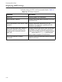
Configuring SNMP Settings . . . . . . . . . . . . . . . . . . . . . . . . . . . . . . . . . . . . . . . . . . . . . . . . . . . . . . . . . . . . . . . . . . . . . . . . . . . . . . .
Displaying SNMP Settings . . . . . . . . . . . . . . . . . . . . . . . . . . . . . . . . . . . . . . . . . . . . . . . . . . . . . . . . . . . . . . . . . . . . . . . . . . . . . . . . .
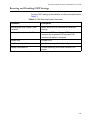
Resetting and Disabling SNMP . . . . . . . . . . . . . . . . . . . . . . . . . . . . . . . . . . . . . . . . . . . . . . . . . . . . . . . . . . . . . . . . . . . . . . . . . . . .
Checking Basic Connectivity . . . . . . . . . . . . . . . . . . . . . . . . . . . . . . . . . . . . . . . . . . . . . . . . . . . . . . . . . . . . . . . . . . . . . . . . . . . . . . . . . . .
Ping . . . . . . . . . . . . . . . . . . . . . . . . . . . . . . . . . . . . . . . . . . . . . . . . . . . . . . . . . . . . . . . . . . . . . . . . . . . . . . . . . . . . . . . . . . . . . . . . . . . . . .
Traceroute. . . . . . . . . . . . . . . . . . . . . . . . . . . . . . . . . . . . . . . . . . . . . . . . . . . . . . . . . . . . . . . . . . . . . . . . . . . . . . . . . . . . . . . . . . . . . . . .
2-14
2-14
2-14
2-17
2-18
2-19
2-20
2-21
2-21
2-25
2-25
2-26
2-26
2-26
2-26
2-28
2-29
2-30
2-30
2-30
Chapter 3
Configuring Switch Ports . . . . . . . . . . . . . . . . . . . . . . . . . . . . . . . . . . . . . . . . . . . . . . . . . . . . . . . . . . . . . . . . . . . . . . . . . . . . . . . . . . . . . .3-1
Enabling and Disabling Ports . . . . . . . . . . . . . . . . . . . . . . . . . . . . . . . . . . . . . . . . . . . . . . . . . . . . . . . . . . . . . . . . . . . . . . . . . . . . . . . . . . . .3-2
Configuring Port Speed and Duplex Setting . . . . . . . . . . . . . . . . . . . . . . . . . . . . . . . . . . . . . . . . . . . . . . . . . . . . . . . . . . . . . . . . . . . . . .3-3
Turning Off Autonegotiation for a Gigabit Ethernet Port. . . . . . . . . . . . . . . . . . . . . . . . . . . . . . . . . . . . . . . . . . . . . . . . . . . . . .3-3
Port Commands. . . . . . . . . . . . . . . . . . . . . . . . . . . . . . . . . . . . . . . . . . . . . . . . . . . . . . . . . . . . . . . . . . . . . . . . . . . . . . . . . . . . . . . . . . . . . . . . .3-4
Load Sharing on the Switch. . . . . . . . . . . . . . . . . . . . . . . . . . . . . . . . . . . . . . . . . . . . . . . . . . . . . . . . . . . . . . . . . . . . . . . . . . . . . . . . . . . . . .3-6
Configuring Load Sharing . . . . . . . . . . . . . . . . . . . . . . . . . . . . . . . . . . . . . . . . . . . . . . . . . . . . . . . . . . . . . . . . . . . . . . . . . . . . . . . . . . .3-6
Load-Sharing Example . . . . . . . . . . . . . . . . . . . . . . . . . . . . . . . . . . . . . . . . . . . . . . . . . . . . . . . . . . . . . . . . . . . . . . . . . . . . . . . . . . . . . .3-8
Verifying the Load Sharing Configuration . . . . . . . . . . . . . . . . . . . . . . . . . . . . . . . . . . . . . . . . . . . . . . . . . . . . . . . . . . . . . . . . . . . .3-9
Port Mirroring . . . . . . . . . . . . . . . . . . . . . . . . . . . . . . . . . . . . . . . . . . . . . . . . . . . . . . . . . . . . . . . . . . . . . . . . . . . . . . . . . . . . . . . . . . . . . . . . . 3-10
Port Mirroring Commands. . . . . . . . . . . . . . . . . . . . . . . . . . . . . . . . . . . . . . . . . . . . . . . . . . . . . . . . . . . . . . . . . . . . . . . . . . . . . . . . . 3-11
Port Mirroring Example . . . . . . . . . . . . . . . . . . . . . . . . . . . . . . . . . . . . . . . . . . . . . . . . . . . . . . . . . . . . . . . . . . . . . . . . . . . . . . . . . . . 3-11
Chapter 4
Virtual LANs (VLANs). . . . . . . . . . . . . . . . . . . . . . . . . . . . . . . . . . . . . . . . . . . . . . . . . . . . . . . . . . . . . . . . . . . . . . . . . . . . . . . . . . . . . . . . . . .4-1
Overview of Virtual LANs . . . . . . . . . . . . . . . . . . . . . . . . . . . . . . . . . . . . . . . . . . . . . . . . . . . . . . . . . . . . . . . . . . . . . . . . . . . . . . . . . . . . . . . .4-1
Benefits . . . . . . . . . . . . . . . . . . . . . . . . . . . . . . . . . . . . . . . . . . . . . . . . . . . . . . . . . . . . . . . . . . . . . . . . . . . . . . . . . . . . . . . . . . . . . . . . . . . .4-1
Types of VLANs . . . . . . . . . . . . . . . . . . . . . . . . . . . . . . . . . . . . . . . . . . . . . . . . . . . . . . . . . . . . . . . . . . . . . . . . . . . . . . . . . . . . . . . . . . . . . . . . .4-3
Port-Based VLANs . . . . . . . . . . . . . . . . . . . . . . . . . . . . . . . . . . . . . . . . . . . . . . . . . . . . . . . . . . . . . . . . . . . . . . . . . . . . . . . . . . . . . . . . . . .4-3
Tagged VLANs . . . . . . . . . . . . . . . . . . . . . . . . . . . . . . . . . . . . . . . . . . . . . . . . . . . . . . . . . . . . . . . . . . . . . . . . . . . . . . . . . . . . . . . . . . . . . .4-5
Generic VLAN Registration Protocol . . . . . . . . . . . . . . . . . . . . . . . . . . . . . . . . . . . . . . . . . . . . . . . . . . . . . . . . . . . . . . . . . . . . . . . . .4-8
Protocol-Based VLANs . . . . . . . . . . . . . . . . . . . . . . . . . . . . . . . . . . . . . . . . . . . . . . . . . . . . . . . . . . . . . . . . . . . . . . . . . . . . . . . . . . . . 4-10
Precedence of Tagged Packets Over Protocol Filters. . . . . . . . . . . . . . . . . . . . . . . . . . . . . . . . . . . . . . . . . . . . . . . . . . . . . . . . 4-13
VLAN Names . . . . . . . . . . . . . . . . . . . . . . . . . . . . . . . . . . . . . . . . . . . . . . . . . . . . . . . . . . . . . . . . . . . . . . . . . . . . . . . . . . . . . . . . . . . . . . . . . . 4-14
Default VLAN . . . . . . . . . . . . . . . . . . . . . . . . . . . . . . . . . . . . . . . . . . . . . . . . . . . . . . . . . . . . . . . . . . . . . . . . . . . . . . . . . . . . . . . . . . . . . 4-14
Configuring VLANs on the Switch. . . . . . . . . . . . . . . . . . . . . . . . . . . . . . . . . . . . . . . . . . . . . . . . . . . . . . . . . . . . . . . . . . . . . . . . . . . . . . 4-15
VLAN Configuration Examples. . . . . . . . . . . . . . . . . . . . . . . . . . . . . . . . . . . . . . . . . . . . . . . . . . . . . . . . . . . . . . . . . . . . . . . . . . . . . 4-17
Displaying VLAN Settings. . . . . . . . . . . . . . . . . . . . . . . . . . . . . . . . . . . . . . . . . . . . . . . . . . . . . . . . . . . . . . . . . . . . . . . . . . . . . . . . . . . . . . 4-18
Deleting VLANs . . . . . . . . . . . . . . . . . . . . . . . . . . . . . . . . . . . . . . . . . . . . . . . . . . . . . . . . . . . . . . . . . . . . . . . . . . . . . . . . . . . . . . . . . . . . . . . 4-19
iv
AT-9108, AT-8518, AT-8525, and AT-8550 User’s Guide
Chapter 5
Forwarding Database (FDB) . . . . . . . . . . . . . . . . . . . . . . . . . . . . . . . . . . . . . . . . . . . . . . . . . . . . . . . . . . . . . . . . . . . . . . . . . . . . . . . . . . . 5-1
Overview of the FDB . . . . . . . . . . . . . . . . . . . . . . . . . . . . . . . . . . . . . . . . . . . . . . . . . . . . . . . . . . . . . . . . . . . . . . . . . . . . . . . . . . . . . . . . . . . . 5-1
FDB Contents. . . . . . . . . . . . . . . . . . . . . . . . . . . . . . . . . . . . . . . . . . . . . . . . . . . . . . . . . . . . . . . . . . . . . . . . . . . . . . . . . . . . . . . . . . . . . . . 5-1
FDB Entry Types . . . . . . . . . . . . . . . . . . . . . . . . . . . . . . . . . . . . . . . . . . . . . . . . . . . . . . . . . . . . . . . . . . . . . . . . . . . . . . . . . . . . . . . . . . . . 5-1
How FDB Entries Get Added. . . . . . . . . . . . . . . . . . . . . . . . . . . . . . . . . . . . . . . . . . . . . . . . . . . . . . . . . . . . . . . . . . . . . . . . . . . . . . . . . 5-2
Associating a QoS Profile with an FDB Entry. . . . . . . . . . . . . . . . . . . . . . . . . . . . . . . . . . . . . . . . . . . . . . . . . . . . . . . . . . . . . . . . . . 5-3
Configuring FDB Entries . . . . . . . . . . . . . . . . . . . . . . . . . . . . . . . . . . . . . . . . . . . . . . . . . . . . . . . . . . . . . . . . . . . . . . . . . . . . . . . . . . . . . . . . . 5-4
FDB Configuration Examples . . . . . . . . . . . . . . . . . . . . . . . . . . . . . . . . . . . . . . . . . . . . . . . . . . . . . . . . . . . . . . . . . . . . . . . . . . . . . . . . 5-5
Displaying FDB Entries . . . . . . . . . . . . . . . . . . . . . . . . . . . . . . . . . . . . . . . . . . . . . . . . . . . . . . . . . . . . . . . . . . . . . . . . . . . . . . . . . . . . . . . . . .5-6
Removing FDB Entries. . . . . . . . . . . . . . . . . . . . . . . . . . . . . . . . . . . . . . . . . . . . . . . . . . . . . . . . . . . . . . . . . . . . . . . . . . . . . . . . . . . . . . . . . . . 5-7
Chapter 6
Spanning Tree Protocol (STP). . . . . . . . . . . . . . . . . . . . . . . . . . . . . . . . . . . . . . . . . . . . . . . . . . . . . . . . . . . . . . . . . . . . . . . . . . . . . . . . . . 6-1
Overview of the Spanning Tree Protocol . . . . . . . . . . . . . . . . . . . . . . . . . . . . . . . . . . . . . . . . . . . . . . . . . . . . . . . . . . . . . . . . . . . . . . . . . 6-1
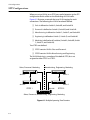
Spanning Tree Protocol Domains . . . . . . . . . . . . . . . . . . . . . . . . . . . . . . . . . . . . . . . . . . . . . . . . . . . . . . . . . . . . . . . . . . . . . . . . . . . . . . . . 6-2
STPD Status for GVRP-Added Ports . . . . . . . . . . . . . . . . . . . . . . . . . . . . . . . . . . . . . . . . . . . . . . . . . . . . . . . . . . . . . . . . . . . . . . . . . . 6-3
Defaults . . . . . . . . . . . . . . . . . . . . . . . . . . . . . . . . . . . . . . . . . . . . . . . . . . . . . . . . . . . . . . . . . . . . . . . . . . . . . . . . . . . . . . . . . . . . . . . . . . . .6-3
STP Configurations. . . . . . . . . . . . . . . . . . . . . . . . . . . . . . . . . . . . . . . . . . . . . . . . . . . . . . . . . . . . . . . . . . . . . . . . . . . . . . . . . . . . . . . . . . . . . . 6-4
Configuring STP on the Switch . . . . . . . . . . . . . . . . . . . . . . . . . . . . . . . . . . . . . . . . . . . . . . . . . . . . . . . . . . . . . . . . . . . . . . . . . . . . . . . . . . 6-7
Displaying STP Settings . . . . . . . . . . . . . . . . . . . . . . . . . . . . . . . . . . . . . . . . . . . . . . . . . . . . . . . . . . . . . . . . . . . . . . . . . . . . . . . . . . . . . . . .6-10
Disabling and Resetting STP . . . . . . . . . . . . . . . . . . . . . . . . . . . . . . . . . . . . . . . . . . . . . . . . . . . . . . . . . . . . . . . . . . . . . . . . . . . . . . . . . . . .6-11
Chapter 7
Quality of Service (QoS). . . . . . . . . . . . . . . . . . . . . . . . . . . . . . . . . . . . . . . . . . . . . . . . . . . . . . . . . . . . . . . . . . . . . . . . . . . . . . . . . . . . . . . .7-1
Overview of Quality of Service . . . . . . . . . . . . . . . . . . . . . . . . . . . . . . . . . . . . . . . . . . . . . . . . . . . . . . . . . . . . . . . . . . . . . . . . . . . . . . . . . . . 7-1
Building Blocks. . . . . . . . . . . . . . . . . . . . . . . . . . . . . . . . . . . . . . . . . . . . . . . . . . . . . . . . . . . . . . . . . . . . . . . . . . . . . . . . . . . . . . . . . . . . . . . . . .7-2
QoS Mode . . . . . . . . . . . . . . . . . . . . . . . . . . . . . . . . . . . . . . . . . . . . . . . . . . . . . . . . . . . . . . . . . . . . . . . . . . . . . . . . . . . . . . . . . . . . . . . . . . . . . .7-3
QoS Profiles. . . . . . . . . . . . . . . . . . . . . . . . . . . . . . . . . . . . . . . . . . . . . . . . . . . . . . . . . . . . . . . . . . . . . . . . . . . . . . . . . . . . . . . . . . . . . . . . . . . . . 7-4
Modifying a QoS Profile . . . . . . . . . . . . . . . . . . . . . . . . . . . . . . . . . . . . . . . . . . . . . . . . . . . . . . . . . . . . . . . . . . . . . . . . . . . . . . . . . . . . . 7-5
Creating and Deleting a QoS Profile . . . . . . . . . . . . . . . . . . . . . . . . . . . . . . . . . . . . . . . . . . . . . . . . . . . . . . . . . . . . . . . . . . . . . . . . . 7-5
QoS Profiles and QoS Mode Details . . . . . . . . . . . . . . . . . . . . . . . . . . . . . . . . . . . . . . . . . . . . . . . . . . . . . . . . . . . . . . . . . . . . . . . . . . . . . . 7-6
The Blackhole QoS Profile . . . . . . . . . . . . . . . . . . . . . . . . . . . . . . . . . . . . . . . . . . . . . . . . . . . . . . . . . . . . . . . . . . . . . . . . . . . . . . . . . . . . . . .7-7
Traffic Groupings and Creating a QoS Policy . . . . . . . . . . . . . . . . . . . . . . . . . . . . . . . . . . . . . . . . . . . . . . . . . . . . . . . . . . . . . . . . . . . . . 7-8
IPQoS Traffic Groupings . . . . . . . . . . . . . . . . . . . . . . . . . . . . . . . . . . . . . . . . . . . . . . . . . . . . . . . . . . . . . . . . . . . . . . . . . . . . . . . . . . . . . 7-9
IPQoS Implementation Rules . . . . . . . . . . . . . . . . . . . . . . . . . . . . . . . . . . . . . . . . . . . . . . . . . . . . . . . . . . . . . . . . . . . . . . . . . . . . . . .7-11
IPQoS Precedence . . . . . . . . . . . . . . . . . . . . . . . . . . . . . . . . . . . . . . . . . . . . . . . . . . . . . . . . . . . . . . . . . . . . . . . . . . . . . . . . . . . . . . . . .7-12
IPQoS Examples . . . . . . . . . . . . . . . . . . . . . . . . . . . . . . . . . . . . . . . . . . . . . . . . . . . . . . . . . . . . . . . . . . . . . . . . . . . . . . . . . . . . . . . . . . .7-13
IPQoS and Multicast Addresses . . . . . . . . . . . . . . . . . . . . . . . . . . . . . . . . . . . . . . . . . . . . . . . . . . . . . . . . . . . . . . . . . . . . . . . . . . . . .7-14
Intra-Subnet QoS . . . . . . . . . . . . . . . . . . . . . . . . . . . . . . . . . . . . . . . . . . . . . . . . . . . . . . . . . . . . . . . . . . . . . . . . . . . . . . . . . . . . . . . . . .7-15
MAC-Based Traffic Groupings . . . . . . . . . . . . . . . . . . . . . . . . . . . . . . . . . . . . . . . . . . . . . . . . . . . . . . . . . . . . . . . . . . . . . . . . . . . . . .7-15
Packet Groupings . . . . . . . . . . . . . . . . . . . . . . . . . . . . . . . . . . . . . . . . . . . . . . . . . . . . . . . . . . . . . . . . . . . . . . . . . . . . . . . . . . . . . . . . . .7-17
Physical and Logical Groupings . . . . . . . . . . . . . . . . . . . . . . . . . . . . . . . . . . . . . . . . . . . . . . . . . . . . . . . . . . . . . . . . . . . . . . . . . . . .7-18
Verifying Configuration and Performance . . . . . . . . . . . . . . . . . . . . . . . . . . . . . . . . . . . . . . . . . . . . . . . . . . . . . . . . . . . . . . . . . . . . . . .7-19
Displaying QoS Information . . . . . . . . . . . . . . . . . . . . . . . . . . . . . . . . . . . . . . . . . . . . . . . . . . . . . . . . . . . . . . . . . . . . . . . . . . . . . . . .7-19
QoS Monitor. . . . . . . . . . . . . . . . . . . . . . . . . . . . . . . . . . . . . . . . . . . . . . . . . . . . . . . . . . . . . . . . . . . . . . . . . . . . . . . . . . . . . . . . . . . . . . .7-20
Modifying a QoS Policy. . . . . . . . . . . . . . . . . . . . . . . . . . . . . . . . . . . . . . . . . . . . . . . . . . . . . . . . . . . . . . . . . . . . . . . . . . . . . . . . . . . . . . . . .7-21
Configuring QoS . . . . . . . . . . . . . . . . . . . . . . . . . . . . . . . . . . . . . . . . . . . . . . . . . . . . . . . . . . . . . . . . . . . . . . . . . . . . . . . . . . . . . . . . . . . . . . .7-22
v
Table of Contents
Chapter 8
IP Unicast Routing . . . . . . . . . . . . . . . . . . . . . . . . . . . . . . . . . . . . . . . . . . . . . . . . . . . . . . . . . . . . . . . . . . . . . . . . . . . . . . . . . . . . . . . . . . . . .8-1
Overview of IP Unicast Routing . . . . . . . . . . . . . . . . . . . . . . . . . . . . . . . . . . . . . . . . . . . . . . . . . . . . . . . . . . . . . . . . . . . . . . . . . . . . . . . . . .8-1
Router Interfaces. . . . . . . . . . . . . . . . . . . . . . . . . . . . . . . . . . . . . . . . . . . . . . . . . . . . . . . . . . . . . . . . . . . . . . . . . . . . . . . . . . . . . . . . . . . .8-2
Populating the Routing Table . . . . . . . . . . . . . . . . . . . . . . . . . . . . . . . . . . . . . . . . . . . . . . . . . . . . . . . . . . . . . . . . . . . . . . . . . . . . . . .8-3
Proxy ARP. . . . . . . . . . . . . . . . . . . . . . . . . . . . . . . . . . . . . . . . . . . . . . . . . . . . . . . . . . . . . . . . . . . . . . . . . . . . . . . . . . . . . . . . . . . . . . . . . . . . . . .8-5
ARP-Incapable Devices . . . . . . . . . . . . . . . . . . . . . . . . . . . . . . . . . . . . . . . . . . . . . . . . . . . . . . . . . . . . . . . . . . . . . . . . . . . . . . . . . . . . . .8-5
Proxy ARP Between Subnets . . . . . . . . . . . . . . . . . . . . . . . . . . . . . . . . . . . . . . . . . . . . . . . . . . . . . . . . . . . . . . . . . . . . . . . . . . . . . . . .8-6
Relative Route Priorities . . . . . . . . . . . . . . . . . . . . . . . . . . . . . . . . . . . . . . . . . . . . . . . . . . . . . . . . . . . . . . . . . . . . . . . . . . . . . . . . . . . . . . . . .8-7
IP Multinetting . . . . . . . . . . . . . . . . . . . . . . . . . . . . . . . . . . . . . . . . . . . . . . . . . . . . . . . . . . . . . . . . . . . . . . . . . . . . . . . . . . . . . . . . . . . . . . . . . .8-8
IP Multinetting Operation . . . . . . . . . . . . . . . . . . . . . . . . . . . . . . . . . . . . . . . . . . . . . . . . . . . . . . . . . . . . . . . . . . . . . . . . . . . . . . . . . . .8-9
IP Multinetting Examples. . . . . . . . . . . . . . . . . . . . . . . . . . . . . . . . . . . . . . . . . . . . . . . . . . . . . . . . . . . . . . . . . . . . . . . . . . . . . . . . . . 8-10
Configuring IP Unicast Routing . . . . . . . . . . . . . . . . . . . . . . . . . . . . . . . . . . . . . . . . . . . . . . . . . . . . . . . . . . . . . . . . . . . . . . . . . . . . . . . . 8-11
Verifying the IP Unicast Routing Configuration. . . . . . . . . . . . . . . . . . . . . . . . . . . . . . . . . . . . . . . . . . . . . . . . . . . . . . . . . . . . . 8-12
Configuring DHCP/BootP Relay . . . . . . . . . . . . . . . . . . . . . . . . . . . . . . . . . . . . . . . . . . . . . . . . . . . . . . . . . . . . . . . . . . . . . . . . . . . . . . . . 8-13
Verifying the DHCP/BootP Relay Configuration . . . . . . . . . . . . . . . . . . . . . . . . . . . . . . . . . . . . . . . . . . . . . . . . . . . . . . . . . . . . 8-13
UDP-Forwarding . . . . . . . . . . . . . . . . . . . . . . . . . . . . . . . . . . . . . . . . . . . . . . . . . . . . . . . . . . . . . . . . . . . . . . . . . . . . . . . . . . . . . . . . . . . . . . 8-14
Configuring UDP-Forwarding . . . . . . . . . . . . . . . . . . . . . . . . . . . . . . . . . . . . . . . . . . . . . . . . . . . . . . . . . . . . . . . . . . . . . . . . . . . . . 8-14
UPD-Forwarding Example . . . . . . . . . . . . . . . . . . . . . . . . . . . . . . . . . . . . . . . . . . . . . . . . . . . . . . . . . . . . . . . . . . . . . . . . . . . . . . . . . 8-15
UDP-Forwarding Commands . . . . . . . . . . . . . . . . . . . . . . . . . . . . . . . . . . . . . . . . . . . . . . . . . . . . . . . . . . . . . . . . . . . . . . . . . . . . . . 8-16
IP Commands . . . . . . . . . . . . . . . . . . . . . . . . . . . . . . . . . . . . . . . . . . . . . . . . . . . . . . . . . . . . . . . . . . . . . . . . . . . . . . . . . . . . . . . . . . . . . . . . . 8-17
Routing Configuration Example . . . . . . . . . . . . . . . . . . . . . . . . . . . . . . . . . . . . . . . . . . . . . . . . . . . . . . . . . . . . . . . . . . . . . . . . . . . . . . . 8-22
Displaying Router Settings . . . . . . . . . . . . . . . . . . . . . . . . . . . . . . . . . . . . . . . . . . . . . . . . . . . . . . . . . . . . . . . . . . . . . . . . . . . . . . . . . . . . 8-24
Resetting and Disabling Router Settings . . . . . . . . . . . . . . . . . . . . . . . . . . . . . . . . . . . . . . . . . . . . . . . . . . . . . . . . . . . . . . . . . . . . . . . 8-25
Chapter 9
RIP and OSPF. . . . . . . . . . . . . . . . . . . . . . . . . . . . . . . . . . . . . . . . . . . . . . . . . . . . . . . . . . . . . . . . . . . . . . . . . . . . . . . . . . . . . . . . . . . . . . . . . . .9-1
Overview . . . . . . . . . . . . . . . . . . . . . . . . . . . . . . . . . . . . . . . . . . . . . . . . . . . . . . . . . . . . . . . . . . . . . . . . . . . . . . . . . . . . . . . . . . . . . . . . . . . . . . .9-1
RIP Versus OSPF. . . . . . . . . . . . . . . . . . . . . . . . . . . . . . . . . . . . . . . . . . . . . . . . . . . . . . . . . . . . . . . . . . . . . . . . . . . . . . . . . . . . . . . . . . . . .9-2
Overview of RIP . . . . . . . . . . . . . . . . . . . . . . . . . . . . . . . . . . . . . . . . . . . . . . . . . . . . . . . . . . . . . . . . . . . . . . . . . . . . . . . . . . . . . . . . . . . . . . . . .9-3
Routing Table. . . . . . . . . . . . . . . . . . . . . . . . . . . . . . . . . . . . . . . . . . . . . . . . . . . . . . . . . . . . . . . . . . . . . . . . . . . . . . . . . . . . . . . . . . . . . . .9-3
Split Horizon. . . . . . . . . . . . . . . . . . . . . . . . . . . . . . . . . . . . . . . . . . . . . . . . . . . . . . . . . . . . . . . . . . . . . . . . . . . . . . . . . . . . . . . . . . . . . . . .9-3
Poison Reverse . . . . . . . . . . . . . . . . . . . . . . . . . . . . . . . . . . . . . . . . . . . . . . . . . . . . . . . . . . . . . . . . . . . . . . . . . . . . . . . . . . . . . . . . . . . . .9-3
Triggered Updates . . . . . . . . . . . . . . . . . . . . . . . . . . . . . . . . . . . . . . . . . . . . . . . . . . . . . . . . . . . . . . . . . . . . . . . . . . . . . . . . . . . . . . . . . .9-3
Route Advertisement of VLANs . . . . . . . . . . . . . . . . . . . . . . . . . . . . . . . . . . . . . . . . . . . . . . . . . . . . . . . . . . . . . . . . . . . . . . . . . . . . . .9-4
RIP Version 1 Versus RIP Version 2 . . . . . . . . . . . . . . . . . . . . . . . . . . . . . . . . . . . . . . . . . . . . . . . . . . . . . . . . . . . . . . . . . . . . . . . . . . .9-4
Overview of OSPF . . . . . . . . . . . . . . . . . . . . . . . . . . . . . . . . . . . . . . . . . . . . . . . . . . . . . . . . . . . . . . . . . . . . . . . . . . . . . . . . . . . . . . . . . . . . . . .9-5
Link-State Database. . . . . . . . . . . . . . . . . . . . . . . . . . . . . . . . . . . . . . . . . . . . . . . . . . . . . . . . . . . . . . . . . . . . . . . . . . . . . . . . . . . . . . . . .9-5
Areas . . . . . . . . . . . . . . . . . . . . . . . . . . . . . . . . . . . . . . . . . . . . . . . . . . . . . . . . . . . . . . . . . . . . . . . . . . . . . . . . . . . . . . . . . . . . . . . . . . . . . . .9-6
Route Redistribution . . . . . . . . . . . . . . . . . . . . . . . . . . . . . . . . . . . . . . . . . . . . . . . . . . . . . . . . . . . . . . . . . . . . . . . . . . . . . . . . . . . . . . . . . . . .9-9
Configuring Route Redistribution. . . . . . . . . . . . . . . . . . . . . . . . . . . . . . . . . . . . . . . . . . . . . . . . . . . . . . . . . . . . . . . . . . . . . . . . . . 9-10
OSPF Timers and Authentication . . . . . . . . . . . . . . . . . . . . . . . . . . . . . . . . . . . . . . . . . . . . . . . . . . . . . . . . . . . . . . . . . . . . . . . . . . 9-11
Configuring RIP . . . . . . . . . . . . . . . . . . . . . . . . . . . . . . . . . . . . . . . . . . . . . . . . . . . . . . . . . . . . . . . . . . . . . . . . . . . . . . . . . . . . . . . . . . . . . . . 9-12
RIP Configuration Example . . . . . . . . . . . . . . . . . . . . . . . . . . . . . . . . . . . . . . . . . . . . . . . . . . . . . . . . . . . . . . . . . . . . . . . . . . . . . . . . . . . . 9-14
Displaying RIP Settings . . . . . . . . . . . . . . . . . . . . . . . . . . . . . . . . . . . . . . . . . . . . . . . . . . . . . . . . . . . . . . . . . . . . . . . . . . . . . . . . . . . . . . . . 9-16
Resetting and Disabling RIP . . . . . . . . . . . . . . . . . . . . . . . . . . . . . . . . . . . . . . . . . . . . . . . . . . . . . . . . . . . . . . . . . . . . . . . . . . . . . . . . . . . 9-17
Configuring OSPF . . . . . . . . . . . . . . . . . . . . . . . . . . . . . . . . . . . . . . . . . . . . . . . . . . . . . . . . . . . . . . . . . . . . . . . . . . . . . . . . . . . . . . . . . . . . . 9-18
OSPF Configuration Example . . . . . . . . . . . . . . . . . . . . . . . . . . . . . . . . . . . . . . . . . . . . . . . . . . . . . . . . . . . . . . . . . . . . . . . . . . . . . . . . . . 9-21
Configuration for ABR1. . . . . . . . . . . . . . . . . . . . . . . . . . . . . . . . . . . . . . . . . . . . . . . . . . . . . . . . . . . . . . . . . . . . . . . . . . . . . . . . . . . . 9-22
Configuration for IR1. . . . . . . . . . . . . . . . . . . . . . . . . . . . . . . . . . . . . . . . . . . . . . . . . . . . . . . . . . . . . . . . . . . . . . . . . . . . . . . . . . . . . . 9-23
Displaying OSPF Settings . . . . . . . . . . . . . . . . . . . . . . . . . . . . . . . . . . . . . . . . . . . . . . . . . . . . . . . . . . . . . . . . . . . . . . . . . . . . . . . . . . . . . . 9-24
Resetting and Disabling OSPF Settings . . . . . . . . . . . . . . . . . . . . . . . . . . . . . . . . . . . . . . . . . . . . . . . . . . . . . . . . . . . . . . . . . . . . . . . . . 9-25
vi
AT-9108, AT-8518, AT-8525, and AT-8550 User’s Guide
Chapter 10
IP Multicast Routing . . . . . . . . . . . . . . . . . . . . . . . . . . . . . . . . . . . . . . . . . . . . . . . . . . . . . . . . . . . . . . . . . . . . . . . . . . . . . . . . . . . . . . . . . .10-1
Overview . . . . . . . . . . . . . . . . . . . . . . . . . . . . . . . . . . . . . . . . . . . . . . . . . . . . . . . . . . . . . . . . . . . . . . . . . . . . . . . . . . . . . . . . . . . . . . . . . . . . . .10-2
DVMRP Overview . . . . . . . . . . . . . . . . . . . . . . . . . . . . . . . . . . . . . . . . . . . . . . . . . . . . . . . . . . . . . . . . . . . . . . . . . . . . . . . . . . . . . . . . . .10-2
PIM-DM Overview . . . . . . . . . . . . . . . . . . . . . . . . . . . . . . . . . . . . . . . . . . . . . . . . . . . . . . . . . . . . . . . . . . . . . . . . . . . . . . . . . . . . . . . . .10-2
IGMP Overview . . . . . . . . . . . . . . . . . . . . . . . . . . . . . . . . . . . . . . . . . . . . . . . . . . . . . . . . . . . . . . . . . . . . . . . . . . . . . . . . . . . . . . . . . . . .10-3
Configuring IP Multicasting Routing . . . . . . . . . . . . . . . . . . . . . . . . . . . . . . . . . . . . . . . . . . . . . . . . . . . . . . . . . . . . . . . . . . . . . . . . . . . .10-4
Configuration Example. . . . . . . . . . . . . . . . . . . . . . . . . . . . . . . . . . . . . . . . . . . . . . . . . . . . . . . . . . . . . . . . . . . . . . . . . . . . . . . . . . . . . . . . .10-8
Configuration for IR1. . . . . . . . . . . . . . . . . . . . . . . . . . . . . . . . . . . . . . . . . . . . . . . . . . . . . . . . . . . . . . . . . . . . . . . . . . . . . . . . . . . . . . .10-9
Displaying IP Multicast Routing Settings . . . . . . . . . . . . . . . . . . . . . . . . . . . . . . . . . . . . . . . . . . . . . . . . . . . . . . . . . . . . . . . . . . . . . . 10-10
Deleting and Resetting IP Multicast Settings . . . . . . . . . . . . . . . . . . . . . . . . . . . . . . . . . . . . . . . . . . . . . . . . . . . . . . . . . . . . . . . . . . 10-11
Chapter 11
IPX Routing . . . . . . . . . . . . . . . . . . . . . . . . . . . . . . . . . . . . . . . . . . . . . . . . . . . . . . . . . . . . . . . . . . . . . . . . . . . . . . . . . . . . . . . . . . . . . . . . . . .11-1
Overview of IPX . . . . . . . . . . . . . . . . . . . . . . . . . . . . . . . . . . . . . . . . . . . . . . . . . . . . . . . . . . . . . . . . . . . . . . . . . . . . . . . . . . . . . . . . . . . . . . . .11-1
Router Interfaces . . . . . . . . . . . . . . . . . . . . . . . . . . . . . . . . . . . . . . . . . . . . . . . . . . . . . . . . . . . . . . . . . . . . . . . . . . . . . . . . . . . . . . . . . .11-1
IPX Routing Performance . . . . . . . . . . . . . . . . . . . . . . . . . . . . . . . . . . . . . . . . . . . . . . . . . . . . . . . . . . . . . . . . . . . . . . . . . . . . . . . . . .11-2
IPX Encapsulation Types . . . . . . . . . . . . . . . . . . . . . . . . . . . . . . . . . . . . . . . . . . . . . . . . . . . . . . . . . . . . . . . . . . . . . . . . . . . . . . . . . . .11-3
Populating the Routing Table . . . . . . . . . . . . . . . . . . . . . . . . . . . . . . . . . . . . . . . . . . . . . . . . . . . . . . . . . . . . . . . . . . . . . . . . . . . . . .11-3
IPX/RIP Routing . . . . . . . . . . . . . . . . . . . . . . . . . . . . . . . . . . . . . . . . . . . . . . . . . . . . . . . . . . . . . . . . . . . . . . . . . . . . . . . . . . . . . . . . . . . . . . . .11-4
Routing SAP Advertisements . . . . . . . . . . . . . . . . . . . . . . . . . . . . . . . . . . . . . . . . . . . . . . . . . . . . . . . . . . . . . . . . . . . . . . . . . . . . . . .11-5
Configuring IPX . . . . . . . . . . . . . . . . . . . . . . . . . . . . . . . . . . . . . . . . . . . . . . . . . . . . . . . . . . . . . . . . . . . . . . . . . . . . . . . . . . . . . . . . . . . . . . . .11-6
Verifying IPX Router Configuration . . . . . . . . . . . . . . . . . . . . . . . . . . . . . . . . . . . . . . . . . . . . . . . . . . . . . . . . . . . . . . . . . . . . . . . . .11-6
Protocol-Based VLANs for IPX . . . . . . . . . . . . . . . . . . . . . . . . . . . . . . . . . . . . . . . . . . . . . . . . . . . . . . . . . . . . . . . . . . . . . . . . . . . . . .11-7
IPX Commands . . . . . . . . . . . . . . . . . . . . . . . . . . . . . . . . . . . . . . . . . . . . . . . . . . . . . . . . . . . . . . . . . . . . . . . . . . . . . . . . . . . . . . . . . . . . . . . .11-8
IPX Configuration Example . . . . . . . . . . . . . . . . . . . . . . . . . . . . . . . . . . . . . . . . . . . . . . . . . . . . . . . . . . . . . . . . . . . . . . . . . . . . . . . . . . . 11-12
Displaying IPX Settings . . . . . . . . . . . . . . . . . . . . . . . . . . . . . . . . . . . . . . . . . . . . . . . . . . . . . . . . . . . . . . . . . . . . . . . . . . . . . . . . . . . . . . . 11-14
Resetting and Disabling IPX . . . . . . . . . . . . . . . . . . . . . . . . . . . . . . . . . . . . . . . . . . . . . . . . . . . . . . . . . . . . . . . . . . . . . . . . . . . . . . . . . . 11-15
Chapter 12
Access Policies . . . . . . . . . . . . . . . . . . . . . . . . . . . . . . . . . . . . . . . . . . . . . . . . . . . . . . . . . . . . . . . . . . . . . . . . . . . . . . . . . . . . . . . . . . . . . . . .12-1
Overview of Access Policies. . . . . . . . . . . . . . . . . . . . . . . . . . . . . . . . . . . . . . . . . . . . . . . . . . . . . . . . . . . . . . . . . . . . . . . . . . . . . . . . . . . . .12-1
Using Access Policies. . . . . . . . . . . . . . . . . . . . . . . . . . . . . . . . . . . . . . . . . . . . . . . . . . . . . . . . . . . . . . . . . . . . . . . . . . . . . . . . . . . . . . . . . . .12-2
Creating an Access Profile . . . . . . . . . . . . . . . . . . . . . . . . . . . . . . . . . . . . . . . . . . . . . . . . . . . . . . . . . . . . . . . . . . . . . . . . . . . . . . . . . .12-2
Configuring an Access Profile . . . . . . . . . . . . . . . . . . . . . . . . . . . . . . . . . . . . . . . . . . . . . . . . . . . . . . . . . . . . . . . . . . . . . . . . . . . . . .12-2
Applying Access Profiles . . . . . . . . . . . . . . . . . . . . . . . . . . . . . . . . . . . . . . . . . . . . . . . . . . . . . . . . . . . . . . . . . . . . . . . . . . . . . . . . . . .12-2
Access Policies for RIP. . . . . . . . . . . . . . . . . . . . . . . . . . . . . . . . . . . . . . . . . . . . . . . . . . . . . . . . . . . . . . . . . . . . . . . . . . . . . . . . . . . . . .12-3
Access Policies for OSPF. . . . . . . . . . . . . . . . . . . . . . . . . . . . . . . . . . . . . . . . . . . . . . . . . . . . . . . . . . . . . . . . . . . . . . . . . . . . . . . . . . . .12-5
Access Policies for DVMRP . . . . . . . . . . . . . . . . . . . . . . . . . . . . . . . . . . . . . . . . . . . . . . . . . . . . . . . . . . . . . . . . . . . . . . . . . . . . . . . . .12-7
Access Policies for PIM-DM . . . . . . . . . . . . . . . . . . . . . . . . . . . . . . . . . . . . . . . . . . . . . . . . . . . . . . . . . . . . . . . . . . . . . . . . . . . . . . . . .12-8
Making Changes to an Access Profile . . . . . . . . . . . . . . . . . . . . . . . . . . . . . . . . . . . . . . . . . . . . . . . . . . . . . . . . . . . . . . . . . . . . . . . . . . .12-9
Removing an Access Policy . . . . . . . . . . . . . . . . . . . . . . . . . . . . . . . . . . . . . . . . . . . . . . . . . . . . . . . . . . . . . . . . . . . . . . . . . . . . . . . . . . . 12-10
Access Policy Commands. . . . . . . . . . . . . . . . . . . . . . . . . . . . . . . . . . . . . . . . . . . . . . . . . . . . . . . . . . . . . . . . . . . . . . . . . . . . . . . . . . . . . 12-11
Chapter 13
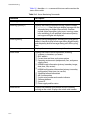
Status Monitoring and Statistics. . . . . . . . . . . . . . . . . . . . . . . . . . . . . . . . . . . . . . . . . . . . . . . . . . . . . . . . . . . . . . . . . . . . . . . . . . . . . .13-1
Status Monitoring . . . . . . . . . . . . . . . . . . . . . . . . . . . . . . . . . . . . . . . . . . . . . . . . . . . . . . . . . . . . . . . . . . . . . . . . . . . . . . . . . . . . . . . . . . . . . .13-1
Port Statistics . . . . . . . . . . . . . . . . . . . . . . . . . . . . . . . . . . . . . . . . . . . . . . . . . . . . . . . . . . . . . . . . . . . . . . . . . . . . . . . . . . . . . . . . . . . . . . . . . .13-3
Port Errors . . . . . . . . . . . . . . . . . . . . . . . . . . . . . . . . . . . . . . . . . . . . . . . . . . . . . . . . . . . . . . . . . . . . . . . . . . . . . . . . . . . . . . . . . . . . . . . . . . . . .13-4
Port Monitoring Display Keys . . . . . . . . . . . . . . . . . . . . . . . . . . . . . . . . . . . . . . . . . . . . . . . . . . . . . . . . . . . . . . . . . . . . . . . . . . . . . . . . . . .13-6
Logging . . . . . . . . . . . . . . . . . . . . . . . . . . . . . . . . . . . . . . . . . . . . . . . . . . . . . . . . . . . . . . . . . . . . . . . . . . . . . . . . . . . . . . . . . . . . . . . . . . . . . . .13-7
Local Logging . . . . . . . . . . . . . . . . . . . . . . . . . . . . . . . . . . . . . . . . . . . . . . . . . . . . . . . . . . . . . . . . . . . . . . . . . . . . . . . . . . . . . . . . . . . . .13-8
Remote Logging. . . . . . . . . . . . . . . . . . . . . . . . . . . . . . . . . . . . . . . . . . . . . . . . . . . . . . . . . . . . . . . . . . . . . . . . . . . . . . . . . . . . . . . . . . .13-9
Logging Commands . . . . . . . . . . . . . . . . . . . . . . . . . . . . . . . . . . . . . . . . . . . . . . . . . . . . . . . . . . . . . . . . . . . . . . . . . . . . . . . . . . . . . 13-10
vii
Table of Contents
RMON . . . . . . . . . . . . . . . . . . . . . . . . . . . . . . . . . . . . . . . . . . . . . . . . . . . . . . . . . . . . . . . . . . . . . . . . . . . . . . . . . . . . . . . . . . . . . . . . . . . . . . . 13-11
About RMON . . . . . . . . . . . . . . . . . . . . . . . . . . . . . . . . . . . . . . . . . . . . . . . . . . . . . . . . . . . . . . . . . . . . . . . . . . . . . . . . . . . . . . . . . . . . 13-11
RMON Features of the Switch . . . . . . . . . . . . . . . . . . . . . . . . . . . . . . . . . . . . . . . . . . . . . . . . . . . . . . . . . . . . . . . . . . . . . . . . . . . . 13-12
Configuring RMON. . . . . . . . . . . . . . . . . . . . . . . . . . . . . . . . . . . . . . . . . . . . . . . . . . . . . . . . . . . . . . . . . . . . . . . . . . . . . . . . . . . . . . . 13-13
Event Actions . . . . . . . . . . . . . . . . . . . . . . . . . . . . . . . . . . . . . . . . . . . . . . . . . . . . . . . . . . . . . . . . . . . . . . . . . . . . . . . . . . . . . . . . . . . . 13-13
Chapter 14
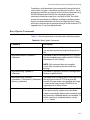
Software Upgrade and Boot Options . . . . . . . . . . . . . . . . . . . . . . . . . . . . . . . . . . . . . . . . . . . . . . . . . . . . . . . . . . . . . . . . . . . . . . . .
Downloading a New Image . . . . . . . . . . . . . . . . . . . . . . . . . . . . . . . . . . . . . . . . . . . . . . . . . . . . . . . . . . . . . . . . . . . . . . . . . . . . . . . . . . . .
Rebooting the Switch . . . . . . . . . . . . . . . . . . . . . . . . . . . . . . . . . . . . . . . . . . . . . . . . . . . . . . . . . . . . . . . . . . . . . . . . . . . . . . . . . . . . .
Saving Configuration Changes. . . . . . . . . . . . . . . . . . . . . . . . . . . . . . . . . . . . . . . . . . . . . . . . . . . . . . . . . . . . . . . . . . . . . . . . . . . . . . . . .
Returning to Factory Defaults . . . . . . . . . . . . . . . . . . . . . . . . . . . . . . . . . . . . . . . . . . . . . . . . . . . . . . . . . . . . . . . . . . . . . . . . . . . . .
Using TFTP to Upload the Configuration . . . . . . . . . . . . . . . . . . . . . . . . . . . . . . . . . . . . . . . . . . . . . . . . . . . . . . . . . . . . . . . . . . . . . . .
Using TFTP to Download the Configuration . . . . . . . . . . . . . . . . . . . . . . . . . . . . . . . . . . . . . . . . . . . . . . . . . . . . . . . . . . . . . . . . . . . .
Upgrading and Accessing BootROM . . . . . . . . . . . . . . . . . . . . . . . . . . . . . . . . . . . . . . . . . . . . . . . . . . . . . . . . . . . . . . . . . . . . . . . . . . .
Upgrading BootROM . . . . . . . . . . . . . . . . . . . . . . . . . . . . . . . . . . . . . . . . . . . . . . . . . . . . . . . . . . . . . . . . . . . . . . . . . . . . . . . . . . . . . .
Accessing the BootROM menu . . . . . . . . . . . . . . . . . . . . . . . . . . . . . . . . . . . . . . . . . . . . . . . . . . . . . . . . . . . . . . . . . . . . . . . . . . . .
Boot Option Commands. . . . . . . . . . . . . . . . . . . . . . . . . . . . . . . . . . . . . . . . . . . . . . . . . . . . . . . . . . . . . . . . . . . . . . . . . . . . . . . . . . . . . . .
14-1
14-1
14-2
14-3
14-3
14-4
14-5
14-6
14-6
14-6
14-7
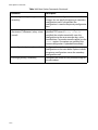
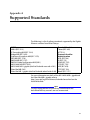
Appendix A
Supported Standards . . . . . . . . . . . . . . . . . . . . . . . . . . . . . . . . . . . . . . . . . . . . . . . . . . . . . . . . . . . . . . . . . . . . . . . . . . . . . . . . . . . . . . . . . A-1
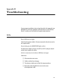
Appendix B
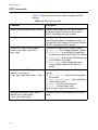
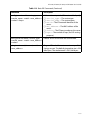
Troubleshooting . . . . . . . . . . . . . . . . . . . . . . . . . . . . . . . . . . . . . . . . . . . . . . . . . . . . . . . . . . . . . . . . . . . . . . . . . . . . . . . . . . . . . . . . . . . . . . .B-1
LEDs . . . . . . . . . . . . . . . . . . . . . . . . . . . . . . . . . . . . . . . . . . . . . . . . . . . . . . . . . . . . . . . . . . . . . . . . . . . . . . . . . . . . . . . . . . . . . . . . . . . . . . . . . . . .B-1
Using the Command-Line Interface . . . . . . . . . . . . . . . . . . . . . . . . . . . . . . . . . . . . . . . . . . . . . . . . . . . . . . . . . . . . . . . . . . . . . . . . . . . . . .B-3
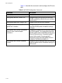
Port Configuration . . . . . . . . . . . . . . . . . . . . . . . . . . . . . . . . . . . . . . . . . . . . . . . . . . . . . . . . . . . . . . . . . . . . . . . . . . . . . . . . . . . . . . . . . .B-5
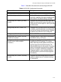
VLANs . . . . . . . . . . . . . . . . . . . . . . . . . . . . . . . . . . . . . . . . . . . . . . . . . . . . . . . . . . . . . . . . . . . . . . . . . . . . . . . . . . . . . . . . . . . . . . . . . . . . . .B-6
STP . . . . . . . . . . . . . . . . . . . . . . . . . . . . . . . . . . . . . . . . . . . . . . . . . . . . . . . . . . . . . . . . . . . . . . . . . . . . . . . . . . . . . . . . . . . . . . . . . . . . . . . . .B-7
Debug Tracing . . . . . . . . . . . . . . . . . . . . . . . . . . . . . . . . . . . . . . . . . . . . . . . . . . . . . . . . . . . . . . . . . . . . . . . . . . . . . . . . . . . . . . . . . . . . . . . . . .B-8
Index . . . . . . . . . . . . . . . . . . . . . . . . . . . . . . . . . . . . . . . . . . . . . . . . . . . . . . . . . . . . . . . . . . . . . . . . . . . . . . . . . . . . . . . . . . . . . . . . . . . . . . Index-1
viii
Preface
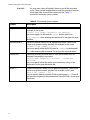
This guide describes the use and configuration of the following
Allied Telesyn Gigabit Ethernet switches running software version
4.x.
Switch Model
Description
AT-8518SX
❏
❏
16 auto-negotiating 10Base-T/100Base-TX ports
Two Gigabit Ethernet ports with short wavelength GBIC connectors
AT-8518LX
❏
❏
16 auto-negotiating 10Base-T/100Base-TX ports
Two Gigabit Ethernet ports with long wavelength GBIC connectors
AT-9108SX
❏
❏
6 Gigabit Ethernet ports with SC connectors
2 Gigabit Ethernet ports with short wavelength GBIC connectors
AT-9108LX
❏
❏
6 Gigabit Ethernet ports with SC connectors
2 Gigabit Ethernet ports with long wavelength GBIC connectors
AT-8525SX
❏
❏
❏
24 auto-negotiating 10Base-T/100Base-TX ports
1 Gigabit Ethernet ports with short wavelength GBIC connector
1 redundant Ethernet Gigabit Ethernet port
AT-8525LX
❏
❏
❏
24 auto-negotiating 10Base-T/100Base-TX ports
1 Gigabit Ethernet ports with long wavelength GBIC connector
1 redundant Ethernet Gigabit Ethernet port
AT-8550SX
❏
❏
❏
48 auto-negotiating 10Base-T/100Base-TX ports
2 Gigabit Ethernet ports with short wavelength GBIC connectors
2 redundant Ethernet Gigabit Ethernet port
AT-8550LX
❏
❏
❏
48 auto-negotiating 10Base-T/100Base-TX ports
2 Gigabit Ethernet ports with long wavelength GBIC connectors
2 redundant Ethernet Gigabit Ethernet port
Preface-i
Audience Description
Audience Description
This guide provides the required information to configure the
software running on the Gigabit Ethernet switches.
This guide is intended for use by network administrators who are
responsible for installing and setting up network equipment. It
assumes a basic working knowledge of the following:
Preface-ii
❑
Local area networks (LANs)
❑
Ethernet concepts
❑
Ethernet switching and bridging concepts
❑
Routing concepts
❑
Internet Protocol (IP) concepts
❑
Routing Information Protocol (RIP) and Open Shortest Path
First (OSPF)
❑
IP Multicast concepts
❑
Distance Vector Multicast Routing Protocol (DVMRP) concepts
❑
Protocol Independent Multicast-Dense Mode (PIM-DM)
concepts
❑
Internet Packet Exchange (IPX) concepts
❑
Simple Network Management Protocol (SNMP)
AT-9108, AT-8518, AT-8525, and AT-8550 User’s Guide
Document Conventions
This guide uses the following conventions:
Note
A note provides additional information.
Caution
A caution indicates that performing or omitting a specific action may
result in equipment damage or loss of data.
Warning
A warning indicates that performing or omitting a specific action may
result in bodily injury.
Preface-iii
Organization
Organization
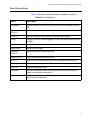
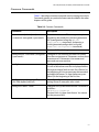
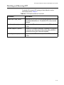
This guide is divided into xx chapters and xx appendices, as follows:
Section Title
Description
Chapter 1, Overview
A description of the Gigabit switch’s software
features and software factory default settings
Chapter 2, Accessing the Switch
The basics of managing the Gigabit switches
Chapter 3, Configuring Switch Ports
The procedures to configure the switch ports
Chapter 4, Virtual LANs (VLANs)
A description of VLAN concepts and the
procedures to implement VLANs on the Gigabit
switches
Chapter 5, Forwarding Database (FDB)
A description of the switch’s forwarding
database and the procedures to configure it
Chapter 6, Spanning Tree Protocol (STP)
An explanation of Spanning Tree features as
implemented by the Gigabit switches
Chapter 7, Quality of Service (QoS)
A description of the concept of Quality of Service
(QoS) and the procedures to configure QoS on
the Gigabit switches
Chapter 8, IP Unicast Routing
The procedures to configure IP routing on
theGigabit switches
Chapter 9, RIP and OSPF
A description of the the IP unicast routing
protocols available on the Gigabit switches
Chapter 10, IP Multicast Routing
A description of IP multicast routing
components and procedures to configure IP
multicast routing on the Gigabit switches
Chapter 11, IPX Routing
The procedures to configure IPX, IPX/RIP, and
IPX/SAP on the Gigabit switches
Chapter 12, Access Policies
The procedures to create access policies on the
Gigabit switches
Chapter 13, Status Monitoring and
Statistics
The procedures on obtaining statistical
information about the Gigabit switches
Chapter 14, Software Upgrade and Boot
Options
The procedures to upgrade the switch software
image, load, and save configurations
Appendix A, Supported Standards
A list of supported software standards
Appendix B, Troubleshooting
Problem resolutions
Preface-iv
AT-9108, AT-8518, AT-8525, and AT-8550 User’s Guide
Related Publications
Allied Telesyn wants our customers to be well informed by providing
the most up-to-date and most easily accessible way to find our
guides and other technical information.
Visit our website at: www.alliedtelesyn/techhome.htm.com and
download the following guide:
AT-9108, AT-8518, AT-8525, and AT-8550 User’s
Command Guide
PN 613-10794-00
The following guides are shipped with the product:
AT-9108, AT-8518, AT-8525 and AT-8550 Installation
Guide
PN 613-10841-00
AT-RPS1000 Installation Guide
PN 613-10755-00
AT-GBIC (SX and LX) Quick Install Guide
PN 613-10757-00
Preface-v
Chapter 1
Overview
This chapter describes the following:
❑ Gigabit Ethernet switch software features
❑ How to use the Gigabit Ethernet switch in your network
configuration
❑ Software factory default settings
Summary of Features
The software features include the following:
❑ Virtual local area networks (VLANs) including support for IEEE
802.1Q and IEEE 802.1p
❑ Spanning Tree Protocol (STP) (IEEE 802.1D) with multiple STP
domains
❑ Policy-Based Quality of Service (PB-QoS)
❑ Wire-speed Internet Protocol (IP) routing
❑ IP Multinetting
❑ DHCP/BootP Relay
❑ Routing Information Protocol (RIP) version 1 and RIP version 2
❑ Open Shortest Path First (OSPF) routing protocol
❑ Wire-speed IP multicast routing support
❑ IGMP snooping to control IP multicast traffic
1-1
Summary of Features
❑ Distance Vector Multicast Routing Protocol (DVMRP)
❑ Protocol Independent Multicast-Dense Mode (PIM-DM)
❑ IPX, IPX/RIP, and IPX/SAP support
❑ Load sharing on multiple ports
❑ Console command-line interface (CLI) connection
❑ Telnet CLI connection
❑ Simple Network Management Protocol (SNMP) support
❑ Remote Monitoring (RMON)
❑ Traffic mirroring for all ports
Note
For more information on the Gigabit switch components, refer to the
switch installation guides.
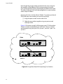
Virtual LANs
(VLANs)
The switches have a VLAN feature that enables you to construct your
broadcast domains without being restricted by physical
connections. Up to 255 VLANs can be defined on the switch. A VLAN
is a group of location- and topology-independent devices that
communicate as if they were on the same physical local area network
(LAN).
Implementing VLANs on your network has the following three
advantages:
❑ It helps to control broadcast traffic. If a device in VLAN
Marketing transmits a broadcast frame, only VLAN Marketing
devices receive the frame.
❑ It provides extra security. Devices in VLAN Marketing can only
communicate with devices on VLAN Sales using routing
services.
❑ It eases the change and movement of devices on networks. If
a device in VLAN Marketing is moved to a port in another part
of the network, all you must do is specify that the new port
belongs to VLAN Marketing.
Note
For more information on VLANs, refer to Chapter 4.
1-2
AT-9108, AT-8518, AT-8525, and AT-8550 User’s Guide
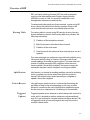
Spanning Tree
Protocol (STP)
The switches support the IEEE 802.1D Spanning Tree Protocol (STP),
which is a bridge-based mechanism for providing fault tolerance on
networks. STP enables you to implement parallel paths for network
traffic, and ensure the following:
❑ Redundant paths are disabled when the main paths are
operational.
❑ Redundant paths are enabled if the main traffic paths fail.
The switch supports up to 64 Spanning Tree Domains (STPDs).
Note
For more information on STP, refer to Chapter 6.
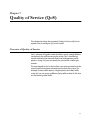
Quality of Service
(QoS)
The switches have Policy-Based Quality of Service (QoS) features that
enable you to specify service levels for different traffic groups. By
default, all traffic is assigned the “normal” QoS policy profile. If
needed, you can create other QoS policies and apply them to
different traffic types so that they have different guaranteed
minimum bandwidth, maximum bandwidth, and priority.
Note
For more information on Quality of Service, refer to Chapter 7.
Unicast Routing
The switches can route IP or IPX traffic between the VLANs that are
configured as virtual router interfaces. Both dynamic and static IP
routes are maintained in the routing table. The following routing
protocols are supported:
❑ RIP version 1
❑ RIP version 2
❑ OSPF
❑ IPX/RIP
Note
For more information on IP unicast routing, refer to Chapter 8. For
more information on IPX/RIP, refer to Chapter 11.
1-3
Summary of Features
IP Multicast
Routing
The switches can use IP multicasting to allow a single IP host to
transmit a packet to a group of IP hosts. The switch softwre supports
multicast routes that are learned by way of the Distance Vector
Multicast Routing Protocol (DVMRP) or Protocol Independent
Multicast-Dense Mode (PIM-DM).
Note
For more information on IP multicast routing, refer to Chapter 10.
Load Sharing
Load sharing allows you to increase bandwidth and resilience by
using a group of ports to carry traffic in parallel between systems.
The sharing algorithm allows the switch to use multiple ports as a
single logical port. For example, VLANs see the load-sharing group as
a single virtual port. The algorithm also guarantees packet
sequencing between clients.
Note
For information on load sharing, refer to Chapter 3.
1-4
AT-9108, AT-8518, AT-8525, and AT-8550 User’s Guide
Memory Requirements
Your Gigabit switch must have 32MB of DRAM in order to support
the features in switch software version 4.0 and above. This is not an
issue for the AT-8525 and the AT-8550 models, and all currently
shipping switches contain 32MB. Earlier models of the switches
shipped with 16MB, and must be upgraded to support the switch
software version 4.0 and above.
To determine the memory size in your switch, use the following
command:
show memory
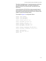
For switches running software version 4.0, the switch indicates the
total DRAM size in megabytes as part of the output. For switches
running previous softwware releases, you must calculate the
memory by taking the sum of the bytes listed under current
free and adding to it the bytes listed under current alloc. If
the sum is greater than 16,000,000, there is no need to upgrade the
memory on the switch. If this is not the case, please contact your
supplier.
1-5
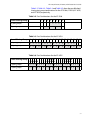
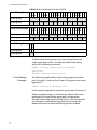
Network Configuration Example
Network Configuration Example
Using Allied Telesyn’s Gigabit Ethernet switches, you can build a
complete end-to-end LAN switching infrastructure that consistently
delivers the same functionality, features, and management interface
throughout. Functionality includes non-blocking switch fabric, wirespeed routing, and Policy-Based QoS. Features include IP routing
with RIP, RIP v2, and OSPF, IP multicast routing support with IGMP,
DVMRP, and PIM-DM, VLAN support by way of IEEE 802.1Q (including
the Generic VLAN Registration Protocol, or GVRP), and standard
packet prioritization using IEEE 802.1p (also known as IEEE 802.1D1998).
The switches deliver the maximum price performance in a small, 3.5
inch-high package. The needs of smaller networks can be satisfied
with AT-8525 and AT-8550 Enterprise desktop switches aggregated
by other Allied Telesyn switches.
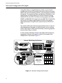
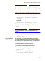
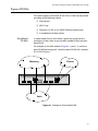
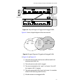
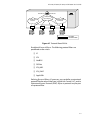
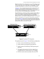
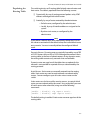
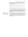
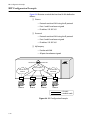
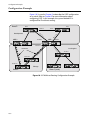
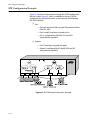
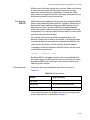
In most networks, desktop switches at the edge of the network are
aggregated with core and segment switches. An example of this
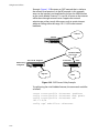
configuration is illustrated in Figure 1-1.
Intranet Switching Architecture
10/100BASE-TX MDI-X NETWORK PORTS
10 /100BASE-T ETHERNET SWITCH
WITH GIGABIT ETHERNET
1000BASE-X NETWORK PORTS
1
2
3
4
5
6
7
8
9
10
11
12
13
14
15
16
18
100BASE-FX FAST ETHERNET SWITCH
LINK /ACTIVITY
1
2
3
4
5
6
10
11
12
13
14
17R
7
8
15
16
18
9
ACTIVITY
LINK
1
17
2
3
L /A
100BASE-FX
4
L /A
L /A
5
6
L /A
7
L /A
PORT ACTIVITY
8
L /A
L /A
RS-232
TERMINAL PORT
STATUS
RS-232
TERMINAL PORT
STATUS
L /A
A
17R 17
ACTIVITY
POWER
LINK
DIAG
TX
RX
D/C
TX
RX
D/C
TX
D/C
RX
TX
D/C
RX
TX
RX
D/C
TX
D/C
RX
TX
RX
D/C
TX
D/C
RX
L /A
LINK /
DISABLED
FULL DUP /
9
10
11
L /A
12
L /A
13
L /A
14
L /A
15
L /A
D/C
16
L /A
L /A
ACTIVITY
HALF DUP
FAULT
COL
L /A
RPS
B
PWR
TX
RX
D/C
TX
RX
D/C
TX
D/C
RX
TX
D/C
RX
TX
RX
D/C
TX
D/C
RX
TX
RX
D/C
TX
D/C
RX
RESET
Enterprise Desktop
Switching
100BASE-FX FAST ETHERNET SWITCH
1
2
3
100BASE-FX
4
5
6
7
PORT ACTIVITY
8
L /A
L /A
L /A
L /A
L /A
L /A
L /A
L /A
D/C
D/C
D/C
D/C
D/C
D/C
D/C
D/C
A
TX
RX
TX
RX
TX
RX
TX
RX
TX
RX
TX
RX
TX
RX
TX
RX
L /A
LINK /
FULL DUP /
9
10
11
L /A
12
L /A
13
L /A
14
L /A
15
L /A
D/C
16
L /A
L /A
ACTIVITY
HALF DUP
FAULT
COL
L /A
RPS
B
PWR
TX
RX
D/C
TX
RX
D/C
TX
D/C
RX
TX
D/C
RX
TX
RX
D/C
TX
D/C
RX
TX
RX
D/C
TX
D/C
RX
RESET
100BASE-FX FAST ETHERNET SWITCH
1
2
3
L /A
100BASE-FX
4
L /A
L /A
5
6
L /A
7
L /A
PORT ACTIVITY
8
L /A
L /A
RS-232
TERMINAL PORT
STATUS
L /A
A
TX
RX
D/C
TX
RX
D/C
TX
D/C
RX
TX
RX
D/C
TX
RX
D/C
TX
D/C
RX
TX
RX
D/C
TX
D/C
RX
L /A
LINK /
FULL DUP /
9
10
11
12
13
14
15
D/C
16
L /A
L /A
L /A
L /A
L /A
L /A
L /A
L /A
D/C
D/C
D/C
D/C
D/C
D/C
D/C
D/C
ACTIVITY
HALF DUP
1
RPS
PWR
TX
RX
TX
RX
TX
RX
TX
RX
TX
RX
TX
RX
TX
RX
TX
RX
1
2
3
4
5
6
7
8
9
10
11
12
13
25
14
26
15
27
16
28
17
29
18
30
19
31
20
32
21
33
22
34
23
35
24
36
37
38
39
40
41
42
43
44
45
46
47
48
FAULT
COL
B
2
7
A 49
49R
13
8
14
3
9
15
4
10
16
5
11
17
10/100BASE-T ETHERNET SWITCH
WITH GIGABIT ETHERNET
6
12
18
RESET
L 49
1
2
3
4
5
6
7
8
9
10
11
12
13
25
14
26
15
27
16
28
17
29
18
30
19
31
20
32
21
33
22
34
23
35
24
36
37
38
39
40
41
42
43
44
45
46
47
48
49
49R
50
50R
L 49
49R
49R
49R
13
19
2
8
14
20
3
9
15
21
4
10
16
22
5
11
17
23
49R
25
31
18
24
LINK ON
20
21
22
23
24
LINK ON
10/100BASE-TX
MDI-X
10/100BASE-TX
MDI-X
DISABLED
10/100BASE-T ETHERNET SWITCH
WITH GIGABIT ETHERNET
6
12
ACTIVITY
19
ACTIVITY
1000BASE-X
1
7
A 49
49
1000BASE-X
26
32
27
33
28
34
29
35
30
36
A 50
50R
37
38
39
49
41
42
L 50
50R
43
44
45
46
47
48
POWER
MGMT.
DISABLED
50
25
26
27
28
29
30
31
32
33
34
35
36
A 50
50R
37
38
39
49
41
42
L 50
50R
43
44
45
46
47
48
50R
POWER
MGMT.
Distributed Core
Switching
GIGABIT ETHERNET SWITCH
1000BASE-X NETWORK PORTS
1
2
3
4
8
ACTIVITY
1
2
3
2
3
4
5
6
7
8
4
5
6
7
8
5
6
7
POWER
DIAG
1
LINK
LINK
DISABLED
10/100BASE-T ETHERNET SWITCH
WITH GIGABIT ETHERNET
1000BASE-X
10/100BASE-TX MDI-X
ACTIVITY
LINK ON
1
2
3
4
5
6
7
8
9
10
11
12
13
14
15
16
17
18
19
20
21
22
23
24
DISABLED
1
7
25
Routers
Core
Switching
25R
2
8
3
4
5
6
9
10
11
12
A 25
25R
13
14
15
16
17
18
L 25
25R
19
20
21
22
23
24
POWER
MGMT.
Data Center
Integrated Server
Switching
ISA_2
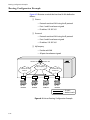
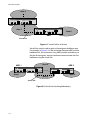
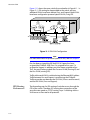
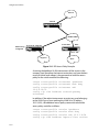
Figure 1-1 Network Configuration Example
1-6
AT-9108, AT-8518, AT-8525, and AT-8550 User’s Guide
A high-speed core switch is used to aggregate Gigabit Ethernet links
from several Allied Telesyn Gigabit Ethernet switches and fast
Ethernet links from access routers.
In this diagram, the Gigabit switches are used for enterprise desktop
connectivity, segment switching, and server switching. The AT-8550
and AT-8525 are used for enterprise desktop connectivity; a
combination of the AT-8518 and AT-8525 is used for segment
switching; and the AT-9108 is used for server switching.
A unique feature of the Gigabit switches is that they provide full layer
3 switching or routing. By enabling core and server switches to route,
the performance penalty of traditional software-based routers can
be removed, and those routers can be used primarily for WAN and
access routing applications. At the desktop, enabling routing on
enterprise desktop switches can increase reliability by dual-homing
the switch to the backbone. In addition, routing on desktop switches
increases the efficiency of the LAN by properly handling IP multicast
packets that are destined for desktops. Segment switches that
deliver wire-speed IP routing can permit easy network migration
with no change to the existing subnet structure.
1-7
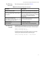
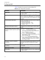
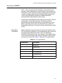
Software Factory Defaults
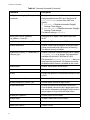
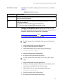
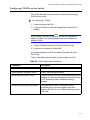
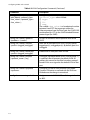
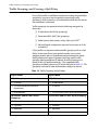
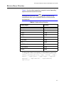
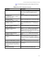
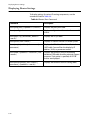
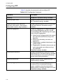
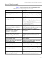
Software Factory Defaults
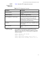
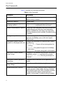
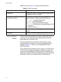
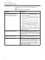
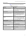
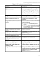
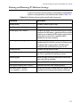
Table 1-1 shows factory defaults for global software features.
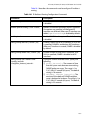
Table 1-1 Gigabit Switches Global Factory Defaults
Item
Default Setting
Serial or Telnet user account
admin with no password and user with no password
Web network management
Enabled
SNMP read community string
public
SNMP write community string
private
RMON
Disabled
BOOTP
Enabled on the default VLAN (default)
QoS
All traffic is part of the default queue in ingress mode
QoS monitoring
Automatic roving
802.1p priority
Recognition enabled
802.3x flow control
Enabled on Gigabit Ethernet ports
Virtual LANs
One VLAN named default; all ports belong to the default
VLAN; the default VLAN belongs to the STPD named s0
802.1Q tagging
All packets are untagged on the default VLAN (default)
Spanning Tree Protocol
Disabled for the switch; enabled for each port in the
STPD
Forwarding database aging period
300 seconds (5 minutes)
IP Routing
Disabled
RIP
Disabled
OSPF
Disabled
IP multicast routing
Disabled
IGMP snooping
Enabled
DVMRP
Disabled
GVRP
Disabled
1-8
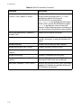
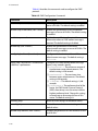
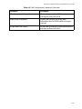
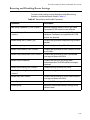
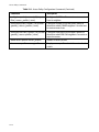
AT-9108, AT-8518, AT-8525, and AT-8550 User’s Guide
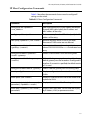
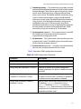
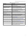
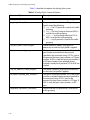
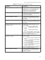
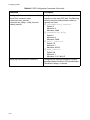
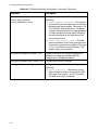
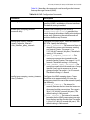
Table 1-1 Gigabit Switches Global Factory Defaults (Continued)
Item
Default Setting
PIM-DM
Disabled
IPX routing
Disabled
NTP
Disabled
DNS
Disabled
Port mirroring
Disabled
Note
For default settings of individual software features, refer to individual
chapters in this guide.
1-9
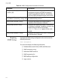
Chapter 2
Accessing the Switch
This chapter provides the following required information to begin
managing the Gigabit switch:
❑ Understanding the command syntax
❑ Line-editing commands
❑ Command history substitution
❑ Configuring the switch for management
❑ Switch management methods
❑ Configuring SNMP
❑ Checking basic connectivity
❑ Using the Simple Network Time Protocol (SNTP)
Note
For configuration changes to be retained through a power cycle or
reboot, you must issue a SAVE command after you have made the
change. For more information on the SAVE command, refer to
Chapter 14.
2-1
AT-9108, AT-8518, AT-8525, and AT-8550 User’s Guide
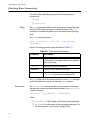
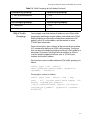
Understanding the Command Syntax
This section describes the steps to take when entering a command.
Refer to the sections that follow for detailed information on using
the command-line interface.
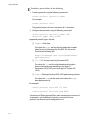
To use the command-line interface (CLI), follow these steps:
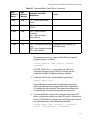
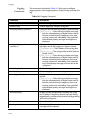
1. When entering a command at the prompt, ensure that you have
the appropriate privilege level.
Most configuration commands require you to have the
administrator privilege level.
2. Enter the command name.
If the command does not include a parameter or values, skip
to Step 3. If the command requires more information,
continue to Step 2a.
a. If the command includes a parameter, enter the parameter
name and values.
b. The value part of the command specifies how you want the
parameter to be set. Values include numerics, strings, or
addresses, depending on the parameter.
3. After entering the complete command, press [Return].
Note
If an asterisk (*) appears in front of the command-line prompt, it
indicates that you have outstanding configuration changes that have
not been saved. For more information on saving configuration
changes, refer to Chapter 14.
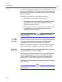
Syntax Helper
The CLI has a built-in syntax helper. If you are unsure of the complete
syntax for a particular command, enter as much of the command as
possible and press [Return]. The syntax helper provides a list of
options for the remainder of the command.
The syntax helper also provides assistance if you have entered an
incorrect command.
Command
Completion with
Syntax Helper
The switch software provides command completion if you press the
[Tab] key. If you enter a partial command, pressing the [Tab] key
posts a list of available options, and places the cursor at the end of
the command.
2-2
AT-9108, AT-8518, AT-8525, and AT-8550 User’s Guide
Abbreviated
Syntax
Abbreviated syntax is the shortest, most unambiguous, allowable
abbreviation of a command or parameter. Typically, this is the first
three letters of the command.
Note
When using abbreviated syntax, you must enter enough characters to
make the command unambiguous and distinguishable to the switch.
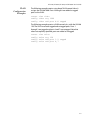
Command
Shortcuts
All named components of the switch configuration must have a
unique name. Components are named using the create command.
When you enter a command to configure a named component, you
do not need to use the keyword of the component. For example, to
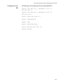
create a VLAN, you must enter a unique VLAN name:
create vlan engineering
Once you have created the VLAN with a unique name, you can then
eliminate the keyword vlan from all other commands that require
the name to be entered. For example, instead of entering the
command
config vlan engineering delete port 1-3,6
you can enter the following shortcut:
config engineering delete port 1-3,6
Numerical
Ranges
Commands that require you to enter one or more port numbers on a
switch use the parameter <portlist> in the syntax. A portlist can
be a range of numbers, for example:
port 1-3
You can add additional port numbers to the list, separated by a
comma:
port 1-3,6,8
Names
All named components of the switch configuration must have a
unique name. Names must begin with an alphabetical character and
are delimited by whitespace, unless enclosed in quotation marks.
2-3
Understanding the Command Syntax
Symbols
You may see a variety of symbols shown as part of the command
syntax. These symbols explain how to enter the command, and you
do not type them as part of the command itself. Table 2-1
summarizes command syntax symbols.
Table 2-1 Command Syntax Symbols
Symbol
Description
angle brackets < >
Enclose a variable or value. You must specify the variable or value. For
example, in the syntax
config vlan <name> ipaddress <ip_address>
you must supply a VLAN name for <name> and an address for
<ip_address> when entering the command. Do not type the angle
brackets.
square brackets [ ]
Enclose a required value or list of required arguments. One or more
values or arguments can be specified. For example, in the syntax
disable vlan [<name> | all]
you must specify either the VLAN name for <name>, or the keyword
all when entering the command. Do not type the square brackets.
vertical bar |
Separates mutually exclusive items in a list, one of which must be
entered. For example, in the syntax
config snmp community [readonly | readwrite]
<string>
you must specify either the read or write community string in the
command. Do not type the vertical bar.
braces { }
Enclose an optional value or a list of optional arguments. One or more
values or arguments can be specified. For example, in the syntax
show vlan {<name> | all}
you can specify either a particular VLAN or the keyword all. If you do
not specify an argument, the command will show all VLANs. Do not type
the braces.
2-4
AT-9108, AT-8518, AT-8525, and AT-8550 User’s Guide
Line-Editing Keys
Table 2-2 describes the line-editing keys available using the CLI.
Table 2-2 Line-Editing Ke y
Key(s)
Description
Backspace
Deletes character to the left of cursor and shifts the remainder of line to
left.
Delete or
[Ctrl] + D
Deletes character under cursor and shifts the remainder of line to left.
[Ctrl] + K
Deletes characters from under cursor to the end of the line.
Insert
Toggles on and off. When toggled on, inserts text and shifts previous text
to right.
Left Arrow
Moves cursor to left.
Right Arrow
Moves cursor to right.
Home or
[Ctrl] + A
Moves cursor to first character in line.
End or [Ctrl] + E
Moves cursor to last character in line.
[Ctrl] + L
Clears the screen and movers the cursor to the beginning of the line.
[Ctrl] + U
Clears all characters typed from the cursor to the beginning of the line.
[Ctrl] + W
Deletes the previous word.
Up Arrow
Displays the previous command in the command history buffer and
places cursor at end of command.
Down Arrow
Displays the next command in the command history buffer and places
cursor at end of command.
2-5
Command History
Command History
The switch software “remembers” the last 49 commands you enter.
You can display a list of these commands by using the following
command:
history
2-6
AT-9108, AT-8518, AT-8525, and AT-8550 User’s Guide
Common Commands
Table 2-3 describes common commands used to manage the switch.
Commands specific to a particular feature are described in the other
chapters of this guide.
Table 2-3 Common Commands
Command
Description
create account [admin | user]
<username> {encrypted} {<password>}
Creates a user account. The encrypted option
should only be used by the switch to generate an
ASCII configuration (using the upload
configuration command), and parsing a
switch-generated configuration (using the
download configuration command).
create vlan <name>
Creates a VLAN with the given name.
config account <username> {encrypted}
{<password>}
Configures a user account password. Passwords
must have a minimum of 4 characters and can have
a maximum of 12 characters. User names and
passwords are case-sensitive.
config banner
Configures the banner string. You can enter up to
24 rows of 80-column text that is displayed before
the login prompt of each session. Press [Return] at
the beginning of a line to terminate the command
and apply the banner. To clear the banner, press
[Return] at the beginning of the first line.
config ports <portlist> auto off {speed
[10 | 100]} duplex [half | full]
Manually configures the port speed and duplex
setting of one or more ports on a switch.
config time <date> <time>
Configures the system date and time. The format is
as follows:
mm/dd/yyyy hh:mm:ss
The time uses a 24-hour clock format. You cannot
set the year past 2023.
2-7
Common Commands
Table 2-3 Common Commands (Continued)
Command
Description
config timezone <gmt_offset> {autodst |
noautodst}
Configures the time zone information to the
configured offset from GMT time. The format of
gmt_offset is +/- minutes from GMT time.
Specify:
❑ autodst — Enables automatic Daylight
Savings Time change
❑ nosautodst — Disables automatic Daylight
Savings Time change.
The default setting is autodst.
config vlan <name> ipaddress
<ip_address> {<mask>}
Configures an IP address and subnet mask for a
VLAN.
enable bootp vlan [<name> | all]
Enables BootP for one or more VLANs.
enable idletimeout
Enables a timer that disconnects all sessions (both
Telnet and console) after 20 minutes of inactivity.
The default setting is disabled.
enable license [basic_L3 | advanced_L3]
<license_key>
Enables a particular software feature license. Specify
<license_key> as an integer. This command is
available only on the AT-8550 and AT-8525.
The command unconfig switch all does not
clear licensing information. This feature cannot be
disabled once the license is enabled on the switch.
enable telnet
Enables Telnet access to the switch.
help
Displays a command summary list.
history
Displays the previous 49 commands entered on the
switch.
clear session <number>
Terminates a Telnet session from the switch.
disable bootp vlan [<name> | all]
Disables BootP for one or more VLANs.
disable idletimeout
Disables the timer that disconnects all sessions.
Once disabled, console sessions remain open until
the switch is rebooted or you logoff. Telnet sessions
remain open until you close the Telnet client.
disable port <portlist>
Disables a port on the switch.
disable telnet
Disables Telnet access to the switch.
delete account <username>
Deletes a user account.
delete vlan <name>
Deletes a VLAN.
2-8
AT-9108, AT-8518, AT-8525, and AT-8550 User’s Guide
Table 2-3 Common Commands (Continued)
Command
Description
unconfig switch {all}
Resets all switch parameters (with the exception of
defined user accounts, and date and time
information) to the factory defaults. If you specify
the keyword all, the user account information is
reset as well.
show banner
Displays the user-configured banner.
2-9
Configuring Management Access
Configuring Management Access
The switch software supports the following two level levels of
management:
❑ User
❑ Administrator
A user-level account has viewing access to all manageable
parameters, with the exception of the following:
❑ User account database
❑ SNMP community strings
A user-level account can use the ping command to test device
reachability, and change the password assigned to the account
name. If you have logged on with user capabilities, the commandline prompt ends with a (>) sign. For example:
8550:2>
An administrator-level account can view and change all switch
parameters. It can also add and delete users, and change the
password associated with any account name. The administrator can
disconnect a management session that has been established by way
of a Telnet connection. If this happens, the user logged on by way of
the Telnet connection is notified that the session has been
terminated.
If you have logged on with administrator capabilities, the commandline prompt ends with a (#) sign. For example:
8550:18#
The prompt text is taken from the SNMP sysname setting. The
number that follows the colon indicates the sequential
line/command number.
If an asterisk (*) appears in front of the command-line prompt, it
indicates that you have outstanding configuration changes that
have not been saved. For example:
*8550:19#
Note
For more information on saving configuration changes, refer to
Chapter 14.
2-10
AT-9108, AT-8518, AT-8525, and AT-8550 User’s Guide
Default Accounts
By default, the switch is configured with two accounts, as shown in
Table 2-4.
Table 2-4 Default Accounts
Account Name
Access Level
admin
This user can access and change all manageable parameters. The admin
account cannot be deleted.
user
This user can view (but not change) all manageable parameters, with the
following exceptions:
❑ This user cannot view the user account database.
❑ This user cannot view the SNMP community strings.
Changing the Default Password. Default accounts do not have
passwords assigned to them. Passwords must have a minimum of 4
characters and can have a maximum of 12 characters.
Note
User names and passwords are case-sensitive.
To add a password to the default admin account, follow these
steps:
1. Log in to the switch using the name admin.
2. At the password prompt, press [Return].
3. Add a default admin password by typing the following:
config account admin
4. Enter the new password at the prompt.
5. Re-enter the new password at the prompt.
To add a password to the default user account, follow these
steps:
1. Log in to the switch using the name admin.
2. At the password prompt, press [Return], or enter the password
that you have configured for the admin account.
3. Add a default user password by typing the following:
config account user
4. Enter the new password at the prompt.
5. Re-enter the new password at the prompt.
2-11
Configuring Management Access
Note
If you forget your password while logged out of the command-line
interface, contact your local technical support representative, who
will advise on your next course of action.
Creating a
Management
Account
The switch can have a total of 16 management accounts. You can use
the default names (admin and user), or you can create new names
and passwords for the accounts. Passwords must have a minimum of
4 characters and can have a maximum of 12 characters.
To create a new account, follow these steps:
1. Log in to the switch as admin.
2. At the password prompt, press [Return], or enter the password
that you have configured for the admin account.
3. Add a new user by using the following command:
create account [admin | user] <username>
{encrypted}
4. Enter the password at the prompt.
5. Re-enter the password at the prompt.
Viewing Accounts. To view the accounts that have been created,
you must have administrator privileges. Use the following command
to see the accounts:
show accounts
Deleting an Account. To delete a account, you must have
administrator privileges. Use the following command to delete an
account:
delete account <username>
Note
The account name admin cannot be deleted.
2-12
AT-9108, AT-8518, AT-8525, and AT-8550 User’s Guide
Methods of Managing the Switch
You can manage the switch using the following methods:
❑ Access the CLI by connecting a terminal (or workstation with
terminal-emulation software) to the console port.
❑ Access the CLI over a TCP/IP network using a Telnet
connection.
❑ Use an SNMP Network Manager over a network running the IP
protocol.
The switch can support up to multiple user sessions concurrently, as
follows:
❑ One console session
❑ Eight Telnet sessions
Using the
Console Interface
The CLI built into the switch is accessible by way of the 9-pin, RS-232
port labeled console, located on the back of the Switch.
Note
For more information on the console port pinouts, refer to the switch
hardware installation guide.
Once the connection is established, you will see the switch prompt
and you may log in.
2-13
Using Telnet
Using Telnet
Any workstation with a Telnet facility should be able to
communicate with the switch over a TCP/IP network.
Up to eight active Telnet sessions can access the switch concurrently.
If idle timeouts are enabled, the Telnet connection will time out
after 20 minutes of inactivity. If a connection to a Telnet session is
lost inadvertently, the switch terminates the session within two
hours.
Before you can start a Telnet session, you must set up the IP
parameters described in the section “Configuring Switch IP
Parameters,” later in this chapter. Telnet is enabled by default.
To open the Telnet session, you must specify the IP address of the
device that you want to manage. Check the user manual supplied
with the Telnet facility if you are unsure of how to do this.
Once the connection is established, you will see the switch prompt
and you may log in.
Connecting to
Another Host
Using Telnet
You can Telnet from the current CLI session to another host using the
following command:
telnet [<ipaddress> | <hostname>]
{<port_number>}
If the TCP port number is not specified, the Telnet session defaults to
port 23. Only VT100 emulation is supported.
Configuring
Switch IP
Parameters
To manage the switch by way of a Telnet connection or by using an
SNMP Network Manager, you must first configure the switch IP
parameters.
Using a BootP Server. If you are using IP and you have a Bootstrap
Protocol (BootP) server set up correctly on your network, you must
add the following information to the BootP server:
❑ Switch Media Access Control (MAC) address
❑ IP address
❑ Subnet address mask (optional)
The switch MAC address is found on the rear label of the switch.
Once this is done, the IP address and subnetwork mask for the switch
will be downloaded automatically. You can then start managing the
switch without further configuration.
2-14
AT-9108, AT-8518, AT-8525, and AT-8550 User’s Guide
You can enable BootP on a per-VLAN basis by using the following
command:
enable bootp vlan [<name> | all]
By default, BootP is enabled on the default VLAN.
If you configure the switch to use BootP, the switch IP address is not
retained through a power cycle, even if the configuration has been
saved. To retain the IP address through a power cycle, you must
configure the IP address of the VLAN using the command-line
interface, Telnet, or Web interface.
All VLANs within a switch that are configured to use BootP to get
their IP address use the same MAC address. Therefore, if you are
using BootP relay through a router, the BootP server must be capable
of differentiating its relay based on the gateway portion of the BootP
packet.
Note
For more information on DHCP/BootP relay, refer to Chapter 8.
Manually Configuring the IP Settings. If you are using IP without a
BootP server, you must enter the IP parameters for the switch in
order for the SNMP Network Manager, Telnet software, or Web
interface to communicate with the device. To assign IP parameters to
the switch, you must do the following:
❑ Log in to the switch with administrator privileges.
❑ Assign an IP address and subnetwork mask to a VLAN.
The switch comes configured with a default VLAN named
default. To use Telnet or an SNMP Network Manager, you must
have at least one VLAN on the switch, and it must be assigned
an IP address and subnetwork mask. IP addresses are always
assigned to a VLAN. The switch can be assigned multiple IP
addresses.
Note
For information on creating and configuring VLANs, refer to Chapter
4.
2-15
Using Telnet
To configure the IP settings manually, perform the following
steps:
1. Connect a terminal or workstation running terminal-emulation
software to the console port.
2. At your terminal, press [Return] one or more times until you see
the login prompt.
3. At the login prompt, enter your user name and password. Note
that they are both case-sensitive. Ensure that you have entered a
user name and password with administrator privileges.
– If you are logging in for the first time, use the default user
name admin to log in with administrator privileges. For
example:
login: admin
– Administrator capabilities enable you to access all switch
functions. The default user names have no passwords
assigned.
– If you have been assigned a user name and password with
administrator privileges, enter them at the login prompt.
4. At the password prompt, enter the password and press [Return].
When you have successfully logged in to the switch, the
command-line prompt displays the name of the switch in its
prompt.
5. Assign an IP address and subnetwork mask for the default VLAN
by using the following command:
config vlan <name> ipaddress <ipaddress>
{<subnet_mask>}
For example:
config vlan default ipaddress 123.45.67.8
255.255.255.0
Your changes take effect immediately.
2-16
AT-9108, AT-8518, AT-8525, and AT-8550 User’s Guide
Note
As a general rule, when configuring any IP addresses for the switch,
you can express a subnet mask by using dotted decimal notation, or
by using classless inter-domain routing notation (CIDR). CIDR uses a
forward slash plus the number of bits in the subnet mask. Using CIDR
notation, the command identical to the one above would be:
config vlan default ipaddress 123.45.67.8 / 24
6. Configure the default route for the switch using the following
command:
config iproute add default <ipaddress>
{<metric>}
For example:
config iproute add default 123.45.67.1
7. Save your configuration changes so that they will be in effect after
the next switch reboot, by typing
save
Note
For more information on saving configuration changes, refer to
Chapter 14.
8. When you are finished using the facility, log out of the switch by
typing
logout or quit
Disconnecting a
Telnet Session
An administrator-level account can disconnect a management
session that has been established by way of a Telnet connection. If
this happens, the user logged in by way of the Telnet connection is
notified that the session has been terminated.
To terminate a Telnet session, follow these steps:
1. Log in to the switch with administrator privileges.
2. Determine the session number of the session you want to
terminate by using the following command:
show session
3. Terminate the session by using the following command:
clear session <session_number>
2-17
Using Telnet
Disabling Telnet
Access
By default, Telnet services are enabled on the switch. You can choose
to disable Telnet by entering
disable telnet
To re-enable Telnet on the switch, at the console port enter
enable telnet
You must be logged in as an administrator to enable or disable
Telnet.
2-18
AT-9108, AT-8518, AT-8525, and AT-8550 User’s Guide
IP Host Configuration Commands
Table 2-5 describes the commands that are used to configure IP
settings on the switch.
Table 2-5 IP Host Configuration Commands
Command
Description
config iparp add <ipaddress>
<mac_address>
Adds a permanent entry to the Address Resolution
Protocol (ARP) table. Specify the IP address and
MAC address of the entry.
config iparp delete <ipaddress>
Deletes an entry from the ARP table. Specify the IP
address of the entry.
clear iparp {<ipaddress> | vlan <name>}
Removes dynamic entries in the IP ARP table.
Permanent IP ARP entries are not affected.
config iproute add <ipaddress> <mask>
<gateway> {<metric>}
Adds a static address to the routing table. Use a
value of 255.255.255.255 for mask to indicate a host
entry.
config iproute delete <ipaddress>
<mask> <gateway>
Deletes a static address from the routing table.
config iproute add default <gateway>
{<metric>}
Adds a default gateway to the routing table. A
default gateway must be located on a configured IP
interface. If no metric is specified, the default metric
of 1 is used.
config iproute delete default <gateway>
Deletes a default gateway from the routing table.
show ipconfig {vlan <name>}
Displays configuration information for one or all
VLANs.
show ipstats {vlan <name>}
Displays IP statistics for the CPU of the switch or for
a particular VLAN.
show iproute {priority | vlan <name> |
permanent | <ipaddress> <mask>}
Displays the contents of the IP routing table.
show iparp {<ipaddress | vlan <name> |
permanent}
Displays the IP ARP table. You can filter the display
by IP address, VLAN, or permanent entries.
2-19
Domain Name Service Client Services
Domain Name Service Client Services
The Domain Name Service (DNS) client in ExtremeWare augments
the following commands to allow them to accept either IP addresses
or host names:
❑ telnet
❑ download [image | configuration | bootrom]
❑ upload configuration
❑ ping
❑ traceroute
In addition, the nslookup utility can be used to return the IP
address of a hostname.
Table 2-6 describes the commands used to configure DNS.
Table 2-6 DNS Commands
Command
Description
config dns-client default-domain
<domain_name>
Configures the domain that the DNS client uses if a
fully qualified domain name is not entered. For
example, if the default domain is configured to be
foo.com, executing ping bar searches for
bar.foo.com.
config dns-client add <ipaddress>
Adds a DNS name server(s) to the available server
list for the DNS client. Up to three name servers can
be configured.
config dns-client delete <ipaddress>
Removes a DNS server.
nslookup <hostname>
Displays the IP address of the requested host.
show dns-client
Displays the DNS configuration.
2-20
AT-9108, AT-8518, AT-8525, and AT-8550 User’s Guide
Using the Simple Network Time Protocol
The switch software supports the client portion of the Simple
Network Time Protocol (SNTP) Version 3 based on RFC1769. SNTP
can be used by the switch to update and synchronize its internal
clock from a Network Time Protocol (NTP) server. When enabled, the
switch sends out a periodic query to the indicated NTP server, or the
switch listens to broadcast NTP updates. In addition, the switch
supports the configured setting for Greenwich Mean time (GMT)
offset and the use of Daylight Savings Time. These features have
been tested for year 2000 compliance.
Configuring and
Using SNTP
To use SNTP, follow these steps:
1. Identify the host(s) that are configured as NTP server(s).
Additionally, identify the preferred method for obtaining NTP
updates. The options are for the NTP server to send out
broadcasts, or for switches using NTP to query the NTP server(s)
directly. A combination of both methods is possible. You must
identify the method that should be used for the switch being
configured.
2. Configure the Greenwich Mean Time (GMT) offset and Daylight
Savings Time preference. NTP updates are distributed using GMT
time. To properly display the local time in logs and other
timestamp information, the switch should be configured with the
appropriate offset to GMT based on geographical location.
Table 2-7 describes GMT offsets.
Table 2-7 Greenwich Mean Time Offsets
GMT
Offset in
Hours
GMT
Offset in
Minutes
+0:00
Common Time Zone
References
Cities
+0
GMT - Greenwich Mean
UT or UTC - Universal
(Coordinated)
WET - Western European
London, England; Dublin, Ireland;
Edinburgh, Scotland ; Lisbon,
Portugal; Reykjavik, Iceland ;
Casablanca, Morocco
-1:00
-60
WAT - West Africa
Azores, Cape Verde Islands
-2:00
-120
AT - Azores
-3:00
-180
-4:00
-240
Brasilia, Brazil ; Buenos Aires,
Argentina; Georgetown, Guyana;
AST - Atlantic Standard
Caracas ; La Paz
2-21
Using the Simple Network Time Protocol
Table 2-7 Greenwich Mean Time Offsets (Continued)
GMT
Offset in
Hours
GMT
Offset in
Minutes
Common Time Zone
References
-5:00
-300
EST - Eastern Standard
Bogota, Columbia; Lima, Peru; New
York, NY, Trevor City, MI USA
-6:00
-360
CST - Central Standard
Mexico City, Mexico
Saskatchewan, Canada
-7:00
-420
MST - Mountain Standard
-8:00
-480
PST - Pacific Standard
-9:00
-540
YST - Yukon Standard
-10:00
-600
AHST - Alaska-Hawaii
Standard
CAT - Central Alaska
HST - Hawaii Standard
-11:00
-660
NT - Nome
-12:00
-720
IDLW - International Date Line
West
+1:00
+60
CET - Central European
FWT - French Winter
MET - Middle European
MEWT - Middle European
Winter
SWT - Swedish Winter
Paris, France ; Berlin, Germany;
Amsterdam, The Netherlands ;
Brussels, Belgium ; Vienna, Austria ;
Madrid, Spain; Rome, Italy; Bern,
Switzerland; Stockholm, Sweden;
Oslo, Norway
+2:00
+120
EET - Eastern European,
Russia Zone 1
Athens, Greece; Helsinki, Finland;
Istanbul, Turkey; Jerusalem, Israel;
Harare, Zimbabwe
+3:00
+180
BT - Baghdad, Russia Zone 2
Kuwait; Nairobi, Kenya; Riyadh, Saudi
Arabia; Moscow, Russia; Tehran, Iran
+4:00
+240
ZP4 - Russia Zone 3
Abu Dhabi, UAE; Muscat; Tblisi;
Volgograd; Kabul
+5:00
+300
ZP5 - Russia Zone 4
+5:30
+330
IST – India Standard Time
+6:00
+360
ZP6 - Russia Zone 5
+7:00
+420
WAST - West Australian
Standard
2-22
Cities
Los Angeles, CA, Cupertino, CA,
Seattle, WA USA
New Delhi, Pune, Allahabad, India
AT-9108, AT-8518, AT-8525, and AT-8550 User’s Guide
Table 2-7 Greenwich Mean Time Offsets (Continued)
GMT
Offset in
Hours
GMT
Offset in
Minutes
+8:00
+480
CCT - China Coast, Russia
Zone 7
+9:00
+540
JST - Japan Standard, Russia
Zone 8
+10:00
+600
EAST - East Australian
Standard
GST - Guam Standard
Russia Zone 9
+11:00
+660
+12:00
+720
Common Time Zone
References
Cities
IDLE - International Date Line Wellington, New Zealand; Fiji,
East
Marshall Islands
NZST - New Zealand Standard
NZT - New Zealand
The command syntax to configure GMT offset and usage of
Daylight Savings is as follows:
config timezone <GMT_offset> {autodst |
noautodst}
The GMT_OFFSET is in +/- minutes from the GMT time.
Automatic Daylight Savings Time (DST) changes can be
enabled or disabled. The default setting is enabled.
3. Enable the SNTP client using the following command:
enable sntp-client
Once enabled, the switch sends out a periodic query to the
NTP servers defined later (if configured) or listens to broadcast
NTP updates from the network. The network time information
is automatically saved into the on-board real-time clock.
4. If you would like this switch to use a directed query to the NTP
server, configure the switch to use the NTP server(s). If the switch
listens to NTP broadcasts, skip this step. To configure the switch to
use a directed query, use the following command:
config sntp-client [primary | secondary]
server [<ip_address> | <hostname>]
2-23
Using the Simple Network Time Protocol
NTP queries are first sent to the primary server. If the primary
server does not respond within 1 second, or if it is not
synchronized, the switch queries the secondary server (if one
is configured). If the switch cannot obtain the time, it restarts
the query process. Otherwise, the switch waits for the sntpclient update interval before querying again.
5. Optionally, the interval for which the SNTP client updates the realtime clock of the switch can be changed using the following
command:
config sntp-client update-interval <seconds>
The default sntp-client update-interval value is 64
seconds.
6. You can verify the configuration using the following commands:
show sntp-client
This command provides configuration and statistics associated with
SNTP and its connectivity to the NTP server.
show switch
This command indicates the GMT offset, Daylight Savings Time, and
the current local time.
2-24
AT-9108, AT-8518, AT-8525, and AT-8550 User’s Guide
SNTP
Configuration
Commands
Table 2-8 describes SNTP configuration commands.
Table 2-8 SNTP Configuration Commands
Command
Description
enable sntp-client
Enables Simple Network Time Protocol (SNTP) client
functions.
disable sntp-client
Disables SNTP client functions.
config sntp-client [primary | secondary]
server [<ipaddress> | <host_name>]
Configures an NTP server for the switch to obtain
time information. Queries are first sent to the
primary server. If the primary server does not
respond within 1 second, or if it is not synchronized,
the switch queries the second server.
config sntp-client update-interval
<seconds>
Configures the interval between polling for time
information from SNTP servers. The default setting
is 64 seconds.
show sntp-client
Displays configuration and statistics for the SNTP
client.
SNTP Example
In this example, the switch queries a specific NTP server and a
backup NTP server. The switch is located in Cupertino, CA, and an
update occurs every 20 minutes. The commands to configure the
switch are as follows:
config
enable
config
config
timezone -240 autodst
sntp-client
sntp-client primary server 10.0.1.1
sntp-client secondary server 10.0.1.2
2-25
Using SNMP
Using SNMP
Any Network Manager running the Simple Network Management
Protocol (SNMP) can manage the switch, provided the Management
Information Base (MIB) is installed correctly on the management
station. Each Network Manager provides its own user interface to the
management facilities.
The following sections describe how to get started if you want to use
an SNMP manager. It assumes you are already familiar with SNMP
management. If not, refer to the following publication:
The Simple Book
by Marshall T. Rose
ISBN 0-13-8121611-9
Published by Prentice Hall
Accessing Switch
Agents
To have access to the SNMP agent residing in the switch, at least one
VLAN must have an IP address assigned to it.
Note
For more information on assigning IP addresses, refer to Table 2-3.
Supported MIBs
Configuring
SNMP Settings
Any Network Manager running SNMP can manage the switch,
provided the MIB is installed correctly on the management station. In
addition to private MIBs, the switch supports the standard MIBs
listed in Appendix A.
The following SNMP parameters can be configured on the switch:
❑ Authorized trap receivers — An authorized trap receiver can
be one or more network management stations on your
network. The switch sends SNMP traps to all trap receivers.
You can have a maximum of six trap receivers configured for
each switch. Entries in this list can be created, modified, and
deleted using the RMON2 trapDestTable MIB variable, as
described in RFC 2021.
❑ Authorized managers — An authorized manager can be
either a single network management station, or a range of
addresses (for example, a complete subnet) specified by a
prefix and a mask. The switch can have a maximum of eight
authorized managers.
2-26
AT-9108, AT-8518, AT-8525, and AT-8550 User’s Guide
❑ Community strings — The community strings allow a simple
method of authentication between the switch and the remote
Network Manager. There are two types of community strings
on the switch. Read community strings provide read-only
access to the switch. The default read-only community string
is public. Read-write community strings provide read and
write access to the switch. The default read-write community
string is private. A total of eight community strings can be
configured on the switch. The community string for all
authorized trap receivers must be configured on the switch for
the trap receiver to receive switch-generated traps. SNMP
community strings can contain up to 126 characters.
❑ System contact (optional) — The system contact is a text field
that enables you to enter the name of the person(s)
responsible for managing the switch.
❑ System name — The system name is the name that you have
assigned to this switch. The default name is the model name
of the switch (for example, Summit1).
❑ System location (optional) — Using the system location field,
you can enter an optional location for this switch.
Table 2-9 describes SNMP configuration commands.
Table 2-9 SNMP Configuration Commands
Command
Description
enable snmp access
Turns on SNMP support for the switch.
enable snmp traps
Turns on SNMP trap support.
config snmp add <ipaddress> {<mask>}
Adds the IP address of an SNMP management
station to the access list. Up to 32 addresses can be
specified.
config snmp add trapreceiver
<ipaddress> community <string>
Adds the IP address of a specified trap receiver. The
IP address can be a unicast, multicast, or broadcast.
A maximum of six trap receivers is allowed.
config snmp community [readonly |
readwrite] <string>
Adds an SNMP read or read/write community string.
The default readonly community string is
public. The default readwrite community
string is private. Each community string can have
a maximum of 126 characters, and can be enclosed
by double quotation marks.
2-27
Using SNMP
Table 2-9 SNMP Configuration Commands (Continued)
Command
Description
config snmp delete [<ipaddress>
{<mask>} | all]
Deletes the IP address of a specified SNMP
management station or all SNMP management
stations. If you delete all addresses, any machine
can have SNMP management access to the switch.
config snmp delete trapreceiver
[<ip_address> community <string> | all]
Deletes the IP address of a specified trap receiver or
all authorized trap receivers.
config snmp syscontact <string>
Configures the name of the system contact. A
maximum of 255 characters is allowed.
config snmp sysname <string>
Configures the name of the switch. A maximum of
32 characters is allowed. The default sysname is the
model name of the device (for example,
Summit1). The sysname appears in the switch
prompt.
config snmp syslocation <string>
Configures the location of the switch. A maximum
of 255 characters is allowed.
Displaying
SNMP Settings
To display the SNMP settings configured on the switch, enter the
following command:
show management
This command displays the following information:
❑ Enable/disable state for Telnet, SNMP, and Web access
❑ SNMP community strings
❑ Authorized SNMP station list
❑ SNMP trap receiver list
❑ RMON polling configuration
❑ Login statistics
2-28
AT-9108, AT-8518, AT-8525, and AT-8550 User’s Guide
Resetting and
Disabling SNMP
To reset and disable SNMP settings, use the commands in Table 2-10.
Table 2-10 SNMP Reset and Disable Commands
Command
Description
disable snmp access
Disables SNMP on the switch. Disabling SNMP access does not
affect the SNMP configuration (for example, community
strings).
disable snmp traps
Prevents SNMP traps from being sent from the switch. Does
not clear the SNMP trap receivers that have been configured.
unconfig management
Restores default values to all SNMP-related entries.
2-29
Checking Basic Connectivity
Checking Basic Connectivity
The switch offers the following commands for checking basic
connectivity:
❑ ping
❑ traceroute
Ping
The ping command enables you to send Internet Control Message
Protocol (ICMP) echo messages to a remote IP device. The ping
command is available for both the user and administrator privilege
level.
The ping command syntax is
ping {continuous} {size <n>} [<ip_address> |
<hostname>]
Options for the ping command are described in Table 2-11.
Table 2-11 Ping Command Parameters
Parameter
Description
continuous
Specifies ICMP echo messages to be sent
continuously. This option can be interrupted by
pressing any key.
size <n>
Specifies the size of the packet.
<ipaddress
Specifies the IP address of the host.
<hostname>
Specifies the name of the host. To use the
hostname, you must first configure DNS.
If a ping request fails, the switch continues to send ping messages
until interrupted. Press any key to interrupt a ping request.
Traceroute
The traceroute command enables you to trace the routed path
between the switch and a destination endstation. The traceroute
command syntax is
traceroute [<ip_address> | <hostname>]
where:
❑ ip_address is the IP address of the destination endstation.
❑ hostname is the hostname of the destination endstation. To
use the hostname, you must first configure DNS.
2-30
Chapter 3
Configuring Switch Ports
This chapter describes how to configure ports on the switch. .
Ports on the switch can be configured in the following ways:
❑ Enabling and disabling individual ports
❑ Configuring the port speed (Fast Ethernet ports only)
❑ Configuring half- or full-duplex mode
❑ Creating load-sharing groups on multiple ports
❑ Changing the Quality or Service (QoS) setting for individual
ports
Note
For more information on QoS, refer to Chapter 7.
3-1
Enabling and Disabling Ports
Enabling and Disabling Ports
By default, all ports are enabled. To enable or disable one or more
ports, use the following command:
[enable | disable] port <portlist>
For example, to disable ports 3, 5, and 12 through 15 , enter the
following:
disable port 3,5,12-15
Even though a port is disabled, the link remains enabled for
diagnostic purposes.
3-2
AT-9108, AT-8518, AT-8525, and AT-8550 User’s Guide
Configuring Port Speed and Duplex Setting
By default, the switch is configured to use autonegotiation to
determine the port speed and duplex setting for each port. You can
select to manually configure the duplex setting and the speed of
10/100 Mbps ports, and you can manually configure the duplex
setting on Gigabit Ethernet ports.
Fast Ethernet ports can connect to either 10Base-T or 100Base-T
networks. By default, the ports autonegotiate port speed. You can
also configure each port for a particular speed (either 10 Mbps or 100
Mbps).
Gigabit Ethernet ports are statically set to 1 Gbps, and their speed
cannot be modified.
All ports on the switch can be configured for half-duplex or fullduplex operation. By default, the ports autonegotiate the duplex
setting.
To configure port speed and duplex setting, use the following
command:
config ports <portlist> auto off {speed [10 |
100]} duplex [half | full]
To configure the switch to autonegotiate, use the following
command:
config ports <portlist> auto on
Flow control is supported only on Gigabit Ethernet ports. It is
enabled or disabled as part of autonegotiation. If autonegotiation is
set to off, flow control is disabled. When autonegotiation is turned
on, flow control is enabled.
Turning Off
Autonegotiation
for a Gigabit
Ethernet Port
In certain interoperability situations, it is necessary to turn
autonegotiation off on a Gigabit Ethernet port. Even though a
Gigabit Ethernet port runs only at full duplex and gigabit speeds, the
command that turns off autonegotiation must still include the
duplex setting.
The following example turns autonegotiation off for port 4 (a Gigabit
Ethernet port);
config ports 4 auto off duplex full
3-3
Port Commands
Port Commands
Table 3-1 describes the switch port commands.
Table 3-1 Port Commands
Command
Description
enable learning port <portlist>
Enables MAC address learning on one or more ports. The
default setting is enabled.
enable port <portlist>
Enables a port.
enable sharing <master_port>
grouping <portlist>
Defines a load-sharing group of ports. The ports specified
in <portlist> are grouped to the master port.
enable smartredundancy <portlist> Enables the smart redundancy feature on the redundant
Gigabit Ethernet port. When the Smart Redundancy
feature is enabled, the switch always uses the primary
link when the primary link is available. The default setting
is enabled.
3-4
config ports <portlist> auto on
Enables autonegotiation for the particular port type;
802.3u for 10/100 Mbps ports or 802.3z for Gigabit
Ethernet ports.
config ports <portlist> auto off
{speed [10 | 100]} duplex [half | full]
Changes the configuration of a group of ports. Specify
the following:
❑ auto off — The port will not autonegotiate the
settings.
❑ speed — The speed of the port (for 10/100 Mbps
ports only).
❑ duplex — The duplex setting (half- or full-duplex).
config ports <portlist> displaystring <string>
Configures a user-defined string for a port. The string is
displayed in certain show commands (for example,
show port all info). The string can be up to 16
characters.
config ports <portlist> qosprofile
<qosname>
Configures one or more ports to use a particular QoS
profile.
unconfig ports <portlist> displaystring <string>
Clears the user-defined display string from a port.
disable learning port <portlist>
Disables MAC address learning on one or more ports for
security purposes. If MAC address learning is disabled,
only broadcast traffic, EDP traffic, and packets destined
to a permanent MAC address matching that port
number, are forwarded. The default setting is enabled.
AT-9108, AT-8518, AT-8525, and AT-8550 User’s Guide
Table 3-1 Port Commands (Continued)
Command
Description
disable port <portlist>
Disables a port. Even when disabled, the link is available
for diagnostic purposes.
disable sharing <master_port>
Disables a load-sharing group of ports.
disable smartredundancy
<portlist>
Disables the smart redundancy feature. If the feature is
disabled, the switch changes the active link only when
the current active link becomes inoperable.
restart port <portlist>
Resets autonegotiation for one or more ports by
resetting the physical link.
show ports {<portlist>} collisions
Displays real-time collision statistics.
show ports {<portlist>}
configuration
Displays the port configuration.
show ports {<portlist>} info
Displays detailed system-related information.
show ports {<portlist>} packet
Displays a histogram of packet statistics.
show ports {<portlist>} qosmonitor
Displays real-time QoS statistics. For more information on
QoS, refer to Chapter 7.
show ports {<portlist>} rxerrors
Displays real-time receive error statistics. For more
information on error statistics, refer to Chapter 13.
show ports {<portlist>} stats
Displays real-time port statistics. For more information
on port statistics, refer to Chapter 13.
show ports {<portlist>} txerrors
Displays real-time transmit error statistics. For more
information on error statistics, refer to Chapter 13.
show ports {<portlist>} utilization
Displays real-time port utilization information. Use the
[Spacebar] to toggle between packet, byte, and
bandwidth utilization information.
3-5
Load Sharing on the Switch
Load Sharing on the Switch
Load sharing with switches allows you to increase bandwidth and
resilience between switches by using a group of ports to carry traffic
in parallel between switches. The sharing algorithm allows the
switch to use multiple ports as a single logical port. For example,
VLANs see the load-sharing group as a single logical port. The
algorithm also guarantees packet sequencing between clients.
If a port in a load-sharing group fails, traffic is redistributed to the
remaining ports in the load-sharing group. If the failed port becomes
active again, traffic is redistributed to include that port.
Note
Load sharing must be enabled on both ends of the link, or a network
loop will result.
Load sharing is most useful in cases where the traffic transmitted
from the switch to the load-sharing group is sourced from an equal
or greater number of ports on the switch. For example, traffic
transmitted to a two-port load-sharing group should originate from
a minimum of two other ports on the same switch.
This feature is supported between Allied Telesyn Gigabit Ethernet
switches only, but may be compatible with third-party “trunking” or
sharing algorithms. Check with an Allied Telesyn’s Technical Support
department for more information.
Configuring Load
Sharing
To set up the switch to load share among ports, you must create a
load-sharing group of ports. Load-sharing groups are defined
according to the following rules:
❑ Ports on the switch are divided into groups of two or four.
❑ Ports in a load-sharing group must be contiguous.
❑ Follow the outlined boxes in Table 3-4 through Table 3-5 to
determine the valid port combinations.
❑ The first port in the load-sharing group is configured to be the
“master” logical port. This is the reference port used in
configuration commands. It can be thought of as the logical
port representing the entire port group.
3-6
AT-9108, AT-8518, AT-8525, and AT-8550 User’s Guide
Table 3-2, Table 3-3, Table 3-4 and Table 3-5 show the possible loadsharing port group combinations for the AT-9108, AT-8518, AT-8525,
and AT-8550, respectively.
Table 3-2 Port Combinations for the AT-9108
Load-Sharing Group
1
2
3
4-port groups
2-port groups
x
x
4
5
6
7
x
x
x
x
x
x
x
x
8
Table 3-3 Port Combinations for the AT-8518
Load-Sharing Group
1
2
3
4
5
6
7
8
9 10 11 12 13 14 15 16 17 18
4-port groups
x
x
x
x
x
x
x
x
x
x
x
x
x
x
x
x
2-port groups
x
x
x
x
x
x
x
x
x
x
x
x
x
x
x
x
x
x
Table 3-4 Port Combinations for the AT-8525
Load-Sharing Group
1 1 1 1 1 1 1 1 1 1 2 2 2 2 2 2
1 2 3 4 5 6 7 8 9 0 1 2 3 4 5 6 7 8 9 0 1 2 3 4 5
4-port groups
x x x x x x x x x x x x x x x x x x x x x x x x
2-port groups
x x x x x x x x x x x x x x x x x x x x x x x x
3-7
Load Sharing on the Switch
Table 3-5 Port Combinations for the AT-8550
Load-Sharing Group
1 1 1 1 1 1 1 1 1 1 2 2 2 2 2
1 2 3 4 5 6 7 8 9 0 1 2 3 4 5 6 7 8 9 0 1 2 3 4
4-port groups
x x x x x x x x x x x x x x x x x x x x x x x x
2-port groups
x x x x x x x x x x x x x x x x x x x x x x x x
Load-Sharing Group 2 2 2 2 2 3 3 3 3 3 3 3 3 3 3 4 4 4 4 4 4 4 4 4
5 6 7 8 9 0 1 2 3 4 5 6 7 8 9 0 1 2 3 4 5 6 7 8
4-port groups
x x x x x x x x x x x x x x x x x x x x x x x x
2-port groups
x x x x x x x x x x x x x x x x x x x x x x x x
Load-Sharing Group 4 5
9 0
4-port groups
2-port groups
x x
To define a load-sharing group, you assign a group of ports to a
single, logical port number. To enable or disable a load-sharing
group, use the following commands:
enable sharing <master_port> grouping
<portlist>
disable sharing <master_port>
Load-Sharing
Example
The following example defines a load-sharing group that contains
ports 9 through 12, and uses the first port in the group as the master
logical port 9:
enable sharing 9 grouping 9-12
In this example, logical port 9 represents physical ports 9 through 12.
When using load sharing, you should always reference the master
logical port of the load-sharing group (port 9 in the previous
example) when configuring or viewing VLANs. VLANs configured to
use other ports in the load-sharing group will have those ports
deleted from the VLAN when load sharing becomes enabled.
3-8
AT-9108, AT-8518, AT-8525, and AT-8550 User’s Guide
Note
Do not disable a port that is part of a load-sharing group. Disabling
the port prevents it from forwarding traffic, but still allows the link to
initialize. As a result, a partner switch does receive a valid indication
that the port is not in a forwarding state, and the partner switch will
continue to forward packets.
Verifying the
Load Sharing
Configuration
The screen output resulting from the show ports
configuration command indicates the ports are involved in load
sharing and the master logical port identity.
3-9
Port Mirroring
Port Mirroring
Port-mirroring configures the switch to copy all traffic associated
with one or more ports to a monitor port on the switch. The monitor
port can be connected to a network analyzer or RMON probe for
packet analysis. The switch uses a traffic filter that copies a group of
traffic to the monitor port.
The traffic filter can be defined based on one of the following criteria:
❑ MAC source address/destination address — All data sent to
or received from a particular source or destination MAC
address is copied to the monitor port.
Note
For MAC mirroring to work correctly, the MAC address must already
be present in the forwarding database (FDB). For more information
on the FDB, refer to Chapter 5.
❑ Physical port — All data that traverses the port, regardless of
VLAN configuration, is copied to the monitor port.
❑ VLAN — All data to and from a particular VLAN, regardless of
the physical port configuration, is copied to the monitor port.
❑ Virtual port — All data specific to a VLAN on a specific port is
copied to the monitor port.
Up to eight mirroring filters and one monitor port can be configured
on the switch. Once a port is specified as a monitor port, it cannot be
used for any other function.
Note
Frames that contain errors are not mirrored.
3-10
AT-9108, AT-8518, AT-8525, and AT-8550 User’s Guide
Port Mirroring
Commands
Port mirroring commands are described in Table 3-6.
Table 3-6 Port Mirroring Configuration Command
Command
Description
enable mirroring to <port>
Dedicates a port to be the mirror output port.
config mirroring add [mac <mac_address> |
vlan <name> | port <port> | vlan <name>
port <port>]
Adds a single mirroring filter definition. Up to
eight mirroring definitions can be added. You
can mirror traffic from a MAC address, a VLAN, a
physical port, or a specific VLAN/port
combination.
config mirroring delete [mac
<mac_address> | vlan <name> | port <port>
| vlan <name> port <port> | all}
Deletes a particular mirroring filter definition, or
all mirroring filter definitions.
disable mirroring
Disables port-mirroring.
show mirroring
Displays the port-mirroring configuration.
Port Mirroring
Example
The following example selects port 3 as the mirror port, and sends all
traffic coming into or out of the switch on port 1 to the mirror port:
enable mirroring port 3
config mirroring add port 1
The following example sends all traffic coming into or out of the
switch on port 1 and the VLAN default to the mirror port:
config mirroring add port 1 vlan default
3-11
Chapter 4
Virtual LANs (VLANs)
Setting up Virtual Local Area Networks (VLANs) on the switch eases
many time-consuming tasks of network administration while
increasing efficiency in network operations.
This chapter describes the concept of VLANs and explains how to
implement VLANs on the switch.
Overview of Virtual LANs
The term “VLAN” is used to refer to a collection of devices that
communicate as if they were on the same physical LAN. Any set of
ports (including all ports on the switch) is considered a VLAN. LAN
segments are not restricted by the hardware that physically connects
them. The segments are defined by flexible user groups you create
with the command-line interface.
Benefits
Implementing VLANs on your networks has the following
advantages:
❑ VLANs help to control traffic.
With traditional networks, congestion can be caused by
broadcast traffic that is directed to all network devices,
regardless of whether they require it. VLANs increase the
efficiency of your network because each VLAN can be set up to
contain only those devices that must communicate with each
other.
4-1
Overview of Virtual LANs
❑ VLANs provide extra security.
Devices within each VLAN can only communicate with member
devices in the same VLAN. If a device in VLAN Marketing must
communicate with devices in VLAN Sales, the traffic must cross a
routing device.
❑ VLANs ease the change and movement of devices.
With traditional networks, network administrators spend much of
their time dealing with moves and changes. If users move to a
different subnetwork, the addresses of each endstation must be
updated manually.
For example, with a VLAN, if an endstation in VLAN Marketing is
moved to a port in another part of the network, and retains its
original subnet membership; you must only specify that the new
port is in VLAN Marketing.
4-2
AT-9108, AT-8518, AT-8525, and AT-8550 User’s Guide
Types of VLANs
The switch supports a maximum of 256 VLANs. VLANs can be created
according to the following criteria:
❑ Physical port
❑ 802.1Q tag
❑ Ethernet, LLC SAP, or LLC/SNAP Ethernet protocol type
❑ A combination of these criteria
Port-Based
VLANs
In a port-based VLAN, a VLAN name is given to a group of one or
more ports on the switch. A port can be a member of only one portbased VLAN.
For example, on the G6X module in Figure 4-1, ports 1, 2, and 5 are
part of VLAN Marketing; ports 3 and 4 are part of VLAN Sales; and port
6 is in VLAN Finance.
Marketing
Finance
GIGABIT ETHERNET SWITCH
1000BASE-X NETWORK PORTS
1
2
3
4
8
ACTIVITY
1
2
3
1
2
3
4
5
6
7
8
4
5
6
7
8
5
6
7
POWER
DIAG
LINK
LINK
DISABLED
Sales
Figure 4-1 Example of a Port-Based VLAN
4-3
Types of VLANs
Even though they are physically connected to the same switch, for
the members of the different VLANs to communicate, the traffic
must go through the IP routing functionality provided in the switch.
This means that each VLAN must be configured as a router interface
with a unique IP address.
Spanning Switches with Port-Based VLANs. To create a port-based
VLAN that spans two switches, you must do two things:
❑ Assign the port on each switch to the VLAN.
❑ Cable the two switches together using one port on each
switch per VLAN.
Figure 4-2 illustrates a single VLAN that spans two AT-9108 switches.
All ports on both switches belong to VLAN Sales. The two switches
are connected using slot 8, port 4 on System 1, and slot 1, port 1 on
System 2.
Sales
GIGABIT ETHERNET SWITCH
1000BASE-X NETWORK PORTS
1
2
3
8
ACTIVITY
4
1
2
3
2
3
4
5
6
7
8
4
5
6
7
8
5
6
7
POWER
DIAG
1
LINK
LINK
DISABLED
Switch 1
GIGABIT ETHERNET SWITCH
1000BASE-X NETWORK PORTS
1
2
3
4
8
ACTIVITY
1
2
3
2
3
4
5
6
7
8
4
5
6
7
8
5
6
7
POWER
DIAG
1
LINK
LINK
DISABLED
Switch 2
Figure 4-2 Single Port-Based VLAN Spanning Two Switches
4-4
AT-9108, AT-8518, AT-8525, and AT-8550 User’s Guide
To create multiple VLANs that span two switches in a port-based
VLAN, a port on Switch 1 must be cabled to a port on Switch 2 for
each VLAN you want to have span across the switches. At least one
port on each switch must be a member of the corresponding VLANs,
as well.
Figure 4-3 illustrates two VLANs spanning two switches. On Switch 1,
ports 1-4 are part of VLAN Accounting; ports 5 - 8 are part of VLAN
Engineering. On Switch 2, ports 1-4 are part of VLAN Accounting; ports
5 - 8 are part of VLAN Engineering. VLAN Accounting spans Switch 1
and Switch 2 by way of a connection between Switch 1 port 2 and
Switch 2 port 4. VLAN Engineering spans Switch 1 and Switch 2 by
way of a connection between Switch 1 port 5 and Switch 2 port 8
Accounting
Engineering
1
2
3
4
8
5
7
6
Switch 1
1
2
3
4
8
5
7
6
Switch 2
Figure 4-3 Two Port-Based VLANs Spanning Two Switches
Using is configuration, you can create multiple VLANs that span
multiple switches, in a daisy-chained fashion. Each switch must have
a dedicated port for each VLAN. Each dedicated port must be
connected to a port that is a member of its VLAN on the next switch.
Tagged VLANs
Tagging is a process that inserts a marker (called a tag) into the
Ethernet frame. The tag contains the identification number of a
specific VLAN, called the VLANid.
Note
The use of 802.1Q tagged packets may lead to the appearance of
packets slightly bigger than the current IEEE 802.3/Ethernet
maximum of 1,518 bytes. This may affect packet error counters in
other devices, and may also lead to connectivity problems if non802.1Q bridges or routers are placed in the path.
4-5
Types of VLANs
Uses of Tagged VLANs. Tagging is most commonly used to create
VLANs that span switches. The switch-to-switch connections are
typically called trunks. Using tags, multiple VLANs can span multiple
switches using one or more trunks. In a port-based VLAN, each VLAN
requires its own pair of trunk ports, as shown in Figure 4-3. Using
tags, multiple VLANs can span two switches with a single trunk.
Another benefit of tagged VLANs is the ability to have a port be a
member of multiple VLANs. This is particularly useful if you have a
device (such as a server) that must belong to multiple VLANs. The
device must have a NIC that supports 802.1Q tagging.
A single port can be a member of only one port-based VLAN. All
additional VLAN membership for the port must be accompanied by
tags. In addition to configuring the VLAN tag for the port, the server
must have a Network Interface Card (NIC) that supports 802.1Q
tagging.
Assigning a VLAN Tag. Each VLAN may be assigned an 802.1Q
VLAN tag. As ports are added to a VLAN with an 802.1Q tag defined,
you decide whether each port will use tagging for that VLAN. The
default mode of the switch is to have all ports assigned to the VLAN
named default with an 802.1Q VLAN tag (VLANid) of 1 assigned.
Not all ports in the VLAN must be tagged. As traffic from a port is
forwarded out of the switch, the switch determines (in real time) if
each destination port should use tagged or untagged packet formats
for that VLAN. The switch adds and strips tags, as required, by the
port configuration for that VLAN.
Note
Packets arriving tagged with a VLANid that is not configured in the
switch will be discarded.
Figure 4-4 illustrates the physical view of a network that uses tagged
and untagged traffic.
4-6
AT-9108, AT-8518, AT-8525, and AT-8550 User’s Guide
CentreCOM
MS
M
S
M
MS
Switch 1
M = Marketing
S = Sales
802.1Q
Tagged server
= Tagged port
CentreCOM
MS
M
S
M
S
Switch 2
Figure 4-4 Physical Diagram of Tagged and Untagged Traffic
Figure 4-5 shows a logical diagram of the same network.
Marketing
Switch 1
Port 2
Port 4
Switch 2
Port 1
Port 4
Switch 1
Port 1 *
Port 7 *
Switch 2
Port 2 *
Sales
Switch 1
Port 1
Port 6
Switch 2
Port 7
Port 8
*Tagged Ports
Figure 4-5 Logical Diagram of Tagged and Untagged Traffic
In Figure 4-4 and Figure 4-5:
❑ The trunk port on each switch carries traffic for both VLAN
Marketing and VLAN Sales.
❑ The trunk port on each switch is tagged.
❑ The server connected to slot 1, port 1 on System 1 has a NIC
that supports 802.1Q tagging.
❑ The server connected to slot 1, port 1 on System 1 is a member
of both VLAN Marketing and VLAN Sales.
❑ All other stations use untagged traffic.
4-7
Types of VLANs
As data passes out of the switch, the switch determines if the
destination port requires the frames to be tagged or untagged. All
traffic coming from and going to the server is tagged. Traffic coming
from and going to the trunk ports is tagged. The traffic that comes
from and goes to the other stations on this network is not tagged.
Mixing Port-based and Tagged VLANs. You can configure the
switch using a combination of port-based and tagged VLANs. A
given port can be a member of multiple VLANs, with the stipulation
that only one of its VLANs uses untagged traffic. In other words, a
port can simultaneously be a member of one port-based VLAN and
multiple tag-based VLANs.
Note
For the purposes of VLAN classification, packets arriving on a port
with an 802.1Q tag containing a VLANid of zero are treated as
untagged.
Generic VLAN
Registration
Protocol
The Generic VLAN Registration Protocol (GVRP) allows a LAN device
to signal other neighboring devices that it wishes to receive packets
for one or more VLANs. The GVRP protocol is defined as part of the
IEEE 802.1Q Virtual LANs draft standard. The main purpose of the
protocol is to allow switches to automatically discover some of the
VLAN information that would otherwise have to be manually
configured in each switch. GVRP can also be run by network servers.
These servers are usually configured to join several VLANs, and then
signal the network switches of the VLANs of which they want to be
part.
Figure 4-6 illustrates a network using GVRP.
VLAN
Untag Red,
ged
Switch A VLAN Red, Tag 10
ETHERNET SWITCH
10/100BASE-T ETHERNET
WITH GIGABIT
10/100BASE-TX
MDI-X
1000BASE-X
POWER
ACTIVITY
LINK ON
DISABLED
3
4
5
6
8
9
10
11
12
14
15
18
13
17
25R
16
A 25
20
21
24
19
23
25R
22
L 25
1
7
2
MGMT.
25R
25
,
ed
N Rged
A
VL ntag
U
GVRP: "Send
me traffic for
VLAN tag 10."
GVRP: "Send
me traffic for
VLAN tag 10."
Switch B
GVRP: "Send
me traffic for
VLAN tag 10."
Figure 4-6 Network Example Using GVRP
4-8
AT-9108, AT-8518, AT-8525, and AT-8550 User’s Guide
In Figure 4-6, Switch A is a member of VLAN Red. VLAN Red has the
VLANid 10. Port 1 and port 2 on Switch A are added to the VLAN as
untagged.
The configuration for Switch A is as follows:
create
config
config
enable
vlan red
vlan red tag 10
vlan red add port 1-2 untagged
gvrp
Switch B does not need to be configured with VLAN or tagging
information. Instead, using GVRP, the server connected to Switch B,
and the remainder of the network connected to Switch B provides
Switch B with the information it needs to forward traffic. Switch A
automatically adds port 3 to VLAN Red because Switch A now knows
that there are other devices on port 3 that need access to VLAN Red.
VLANs that are automatically created using GVRP with the VLANid 10
are given names in the format
gvrp vlan xxxx
where xxxx is the VLANid (in decimal) that is discovered by GVRP.
These VLANs are not permanently stored in nonvolatile storage, and
you cannot add or remove ports from these VLANs.
GVRP assumes that the VLANs for which it carries information
operate using VLAN tags, unless explicitly configured otherwise.
Typically, you must configure any untagged VLANs on the switches
at the edges of the network, and the GVRP protocol is used across
the core of the network to automatically configure other switches
using tagged VLANs.
Note
You cannot assign an IP address to a VLAN learned by way of GVRP.
GVRP and Spanning Tree Domains. Because GVRP-learned VLANs
are dynamic, all VLANs created by GVRP use the system defaults and
become members of the default Spanning Tree Domain (STPD), s0.
Because two STPDs cannot exist on the same physical port, if two
GVRP clients attempt to join two different VLANs that belong to two
different STPDs, the second client is refused. You should configure all
potential GVRP VLANs to be members of the same STPD. This
configuration is done automatically, if you have not configured
additional STPDs.
4-9
Types of VLANs
GVRP Commands. Table 4-1 describes GVRP commands.
Table 4-1 GVRP Commands
Command
Description
enable gvrp
Enables the Generic VLAN Registration Protocol (GVRP).
The default setting is disabled.
config gvrp {listen | send | both |
none} {port <portlist>}
Configures the sending and receiving GVRP information
one or all a ports. Options include the following:
❑ listen — Receive GVRP packets.
❑ send — Send GVRP packets.
❑ both — Send and receive GVRP packets.
❑ none — Disable the port from participating in GVRP
operation.
The default setting is both.
disable gvrp
Disables the Generic VLAN Registration Protocol
(GVRP).
show gvrp
Displays the current configuration and status of GVRP.
Protocol-Based
VLANs
Protocol-based VLANs enable you to define a packet filter that the
switch uses as the matching criteria to determine if a particular
packet belongs to a particular VLAN.
Protocol-based VLANs are most often used in situations where
network segments contain hosts running multiple protocols. For
example, in Figure 4-7, the hosts are running both the IP and
NetBIOS protocols.
The IP traffic has been divided into two IP subnets, 192.207.35.0 and
192.207.36.0. The subnets are internally routed by the switch. The
subnets are assigned different VLAN names, Finance and Personnel,
respectively. The remainder of the traffic belongs to the VLAN named
MyCompany. All ports are members of the VLAN MyCompany.
4-10
AT-9108, AT-8518, AT-8525, and AT-8550 User’s Guide
192.207.35.1
192.207.36.1
My Company
192.207.35.0
Finance
1
192.207.36.0
Personnel
2
3
4
= IP traffic
= All other traffic
Figure 4-7 Protocol-Based VLANs
Predefined Protocol Filters. The following protocol filters are
predefined on the switch:
❑ IP
❑ IPX
❑ NetBIOS
❑ DECNet
❑ IPX_8022
❑ IPX_SNAP
❑ AppleTalk
Defining Protocol Filters. If necessary, you can define a customized
protocol filter based on EtherType, Logical Link Control (LLC), and/or
Subnetwork Access Protocol (SNAP). Up to six protocols may be part
of a protocol filter.
4-11
Types of VLANs
To define a protocol filter, do the following:
1. Create a protocol using the following command:
create protocol <protocol_name>
For example:
create protocol fred
The protocol name can have a maximum of 31 characters.
2. Configure the protocol using the following command:
config protocol <protocol_name> add
<protocol_type> <hex_value>
Supported protocol types include:
❑ etype — EtherType
The values for etype are four-digit hexadecimal numbers
taken from a list maintained by the IEEE. This list can be
found at the following URL:
http://standards.ieee.org/regauth/ethert
ype/index.html
❑ llc — LLC Service Advertising Protocol (SAP)
The values for llc are four-digit hexadecimal numbers
that are created by concatenating a two-digit LLC
Destination SAP (DSAP) and a two-digit LLC Source SAP
(SSAP).
❑ snap — Ethertype inside an IEEE SNAP packet encapsulation.
The values for snap are the same as the values for etype,
described previously.
For example:
config protocol fred add llc feff
config protocol fred add snap 9999
A maximum of fifteen protocol filters, each containing a maximum of
six protocols, can be defined. However, no more than seven
protocols can be active and configured for use.
4-12
AT-9108, AT-8518, AT-8525, and AT-8550 User’s Guide
Note
For more information on SNAP for Ethernet protocol types, see
TR 11802-5:1997 (ISO/IEC) [ANSI/IEEE std. 802.1H, 1997 Edition].
Deleting a Protocol Filter. If a protocol filter is deleted from a VLAN,
the VLAN is assigned a protocol filter of none. You can continue to
configure the VLAN. However, no traffic is forwarded to the VLAN
until a protocol is assigned to it.
Precedence of
Tagged Packets
Over Protocol
Filters
If a VLAN is configured to accept tagged packets on a particular port,
incoming packets that match the tag configuration take precedence
over any protocol filters associated with the VLAN.
4-13
VLAN Names
VLAN Names
The switch supports up to 256 different VLANs. Each VLAN is given a
name that can be up to 32 characters. VLAN names can use standard
alphanumeric characters. The following characters are not permitted
in a VLAN name:
❑ Space
❑ Comma
❑ Quotation mark
VLAN names must begin with an alphabetical letter. Quotation
marks can be used to enclose a VLAN name that does not begin with
an alphabetical character, or that contains a space, comma, or other
special character.
VLAN names are locally significant. That is, VLAN names used on one
switch are only meaningful to that switch. If another switch is
connected to it, the VLAN names have no significance to the other
switch.
Note
You should use VLAN names consistently across your entire network.
Default VLAN
The switch ships with one default VLAN that has the following
properties:
❑ The VLAN name is default.
❑ It contains all the ports on a new or initialized switch.
❑ The default VLAN is untagged on all ports. It has an internal
VLANid of 1.
4-14
AT-9108, AT-8518, AT-8525, and AT-8550 User’s Guide
Configuring VLANs on the Switch
This section describes the commands associated with setting up
VLANs on the switch.
To configuring a VLAN:
1. Create and name the VLAN.
2. Assign an IP address and mask (if applicable) to the VLAN, if
needed.
Note
Each IP address and mask assigned to a VLAN must represent a
unique IP subnet. You cannot configure the same IP subnet on
different VLANs.
3. Assign a VLANid, if any ports in this VLAN will use a tag.
4. Assign one or more ports to the VLAN.
As you add each port to the VLAN, decide if the port will use an
802.1Q tag.
Table 4-2 describes the commands used to configure a VLAN.
Table 4-2 VLAN Configuration Commands
Command
Description
create vlan <name>
Creates a named VLAN.
create protocol <protocol_name>
Creates a user-defined protocol.
enable ignore-stp vlan <name>
Enables a VLAN from using STP port information. When
enabled, all virtual ports associated with the VLAN are
in STP forwarding mode. The default setting is
disabled.
config dot1p ethertype <ethertype>
Configures an IEEE 802.1Q Ethertype. Use this
command only if you have another switch that
supports 802.1Q, but uses a different Ethertype value
than 8100.
4-15
Configuring VLANs on the Switch
Table 4-2 VLAN Configuration Commands (Continued)
Command
Description
config protocol <protocol_name>
[add | delete] <protocol_type>
<hex_value> {<protocol_type>
<hex_value>} ...
Configures a protocol filter. Supported
<protocol_type> values include:
❑ etype
❑ llc
❑ snap
The variable <hex_value> is a hexadecimal number
between 0 and FFFF that represents either the
Ethernet protocol type (for EtherType), the DSAP/SSAP
combination (for LLC), or the SNAP-encoded Ethernet
protocol type (for SNAP).
config vlan <name> ipaddress
<ipaddress> {<mask>}
Assigns an IP address and an optional mask to the
VLAN.
config vlan <name> add port
<portlist> {tagged | untagged}
Adds one or more ports to a VLAN. You can specify
tagged port(s), untagged port(s). By default, ports are
untagged.
config vlan <name> delete port
<portlist> {tagged | untagged}
Deletes one or more ports from a VLAN.
config vlan <name> protocol
[<protocol_name> | any]
Configures a protocol-based VLAN. If the keyword any
is specified, then it becomes the default VLAN. All
packets that cannot be classified into other protocolbased VLANs are assigned to the default VLAN of that
port.
config vlan <name> qosprofile
<qosname>
Configures a VLAN to use a particular QoS profile.
Dynamic FDB entries associated with the VLAN are
flushed once the change is committed.
config vlan <name> tag <vlanid>
Assigns a numerical VLANid. The valid range is from 1
to 4095.
4-16
AT-9108, AT-8518, AT-8525, and AT-8550 User’s Guide
VLAN
Configuration
Examples
The following example creates a tag-based VLAN named video. It
assigns the VLANid 1000. Ports 4 through 8 are added as tagged
ports to the VLAN.
create vlan video
config video tag 1000
config video add port 4-8 tagged
The following example creates a VLAN named sales, with the VLANid
120. The VLAN uses both tagged and untagged ports. Ports 1
through 3 are tagged, and ports 4 and 7 are untagged. Note that
when not explicitly specified, ports are added as untagged.
create
config
config
config
vlan sales
sales tag 120
sales add port 1-3 tagged
sales add port 4,7
4-17
Displaying VLAN Settings
Displaying VLAN Settings
To display VLAN settings, use the following command:
show vlan {<name> | all}
The show command displays summary information about each
VLAN, and includes the following:
❑ Name
❑ VLANid
❑ How the VLAN was created (manually or by GVRP)
❑ IP address
❑ STPD information
❑ Protocol information
❑ QoS profile information
❑ Ports assigned
❑ Tagged/untagged status for each port
❑ How the ports were added to the VLAN (manually or by GVRP)
To display protocol information, use the following command:
show protocol {<protocol> | all}
This show command displays protocol information, including the
following:
❑ Protocol name
❑ List of protocol fields
❑ VLANs that use the protocol
4-18
AT-9108, AT-8518, AT-8525, and AT-8550 User’s Guide
Deleting VLANs
To delete a VLAN, or to return VLAN settings to their defaults, use the
commands listed in Table 4-3.
Table 4-3 VLAN Delete and Reset Commands
Command
Description
disable ignore-stp vlan <name>
Allows a VLAN to use STP port information.
unconfig vlan <name> ipaddress
Resets the IP address of the VLAN.
delete vlan <name>
Removes a VLAN.
delete protocol <protocol>
Removes a protocol.
4-19
Chapter 5
Forwarding Database (FDB)
This chapter describes the contents of the forwarding database
(FDB), how the FDB works, and how to configure the FDB.
Overview of the FDB
The switch maintains a database of all media access control (MAC)
addresses received on all of its ports. It uses the information in this
database to decide whether a frame should be forwarded or filtered.
FDB Contents
FDB Entry Types
The database holds up to a maximum of 128K entries. Each entry
consists of the MAC address of the device, an identifier for the port
on which it was received, and an identifier for the VLAN to which the
device belongs. Frames destined for devices that are not in the FDB
are flooded to all members of the VLAN.
The following are three types of entries in the FDB:
❑ Dynamic entries — Initially, all entries in the database are
dynamic. Entries in the database are removed (aged-out) if,
after a period of time (aging time), the device has not
transmitted. This prevents the database from becoming full
with obsolete entries by ensuring that when a device is
removed from the network, its entry is deleted from the
database. Dynamic entries are deleted from the database if
the switch is reset or a power off/on cycle occurs. For more
information about setting the aging time, refer to the section
“Configuring FDB Entries,” later in this chapter.
5-1
Overview of the FDB
❑ Non-aging entries — If the aging time is set to zero, all aging
entries in the database are defined as static, non-aging entries.
This means that they do not age, but they are still deleted if
the switch is reset.
❑ Permanent entries — Permanent entries are retained in the
database if the switch is reset or a power off/on cycle occurs.
The system administrator must make entries permanent. A
permanent entry can either be a unicast or multicast MAC
address. All entries entered by way of the command-line
interface are stored as permanent. The switch can support a
maximum of 64 permanent entries.
Once created, permanent entries stay the same as when they were
created. For example. the permanent entry store is not updated
when any of the following take place:
— A VLAN is deleted.
— A VLANid is changed.
— A port mode is changed (tagged/untagged).
— A port is deleted from a VLAN.
— A port is disabled.
— A port enters blocking state.
— A port QoS setting is changed.
— A port goes down (link down).
❑ Blackhole entries — A blackhole entry configures packets
with a specified MAC destination address to be discarded.
Blackhole entries are useful as a security measure or in special
circumstances where a specific destination address must be
discarded. Blackhole entries are treated like permanent
entries in the event of a switch reset or power off/on cycle.
Blackhole entries are never aged out of the database.
How FDB Entries
Get Added
Entries are added into the FDB in the following two ways:
❑ The switch can learn entries. The system updates its FDB with
the source MAC address from a packet, the VLAN, and the port
identifier on which the source packet is received.
❑ You can enter and update entries using a MIB browser, an
SNMP Network Manager, or the command-line interface (CLI).
5-2
AT-9108, AT-8518, AT-8525, and AT-8550 User’s Guide
Associating a QoS
Profile with an
FDB Entry
You can associate a QoS profile with a MAC address (and VLAN) of a
device that will be dynamically learned. The FDB treats the entry like
a dynamic entry (it is learned, it can be aged out of the database, and
so on). The switch applies the QoS profile as soon as the FDB entry is
learned.
Note
For more information on QoS, refer to Chapter 7.
5-3
Configuring FDB Entries
Configuring FDB Entries
To configure entries in the FDB, use the commands listed in
Table 5-1.
Table 5-1 FDB Configuration Commands
Command
Description
create fdbentry <mac_address> vlan
<name> [blackhole | <portlist> |
dynamic] {qosprofile <qosname>}
Creates an FDB entry. Specify the following:
❑ mac_address — Device MAC address, using
colon separated bytes.
❑ name — VLAN associated with MAC address.
❑ blackhole — Configures the MAC address as a
blackhole entry.
❑ portlist — Port numbers associated with
MAC address.
❑ dynamic — Specifies that the entry will be
learned dynamically. Used to associated a QoS
profile with a dynamically learned entry.
❑ qosname — QoS profile associated with MAC
address.
If more than one port number is associated with a
permanent MAC entry, packets are multicast to the
multiple destinations.
config fdb agingtime <number>
Configures the FDB aging time. The range is 15
through 1,000,000 seconds. The default value is 300
seconds. A value of 0 indicates that the entry should
never be aged out.
enable learning port <portlist>
Enables MAC address learning on one or more
ports.
disable learning port <portlist>
Disables MAC address learning on one or more
ports for security purposes. If MAC address learning
is disabled, only broadcast traffic, EDP traffic, and
packets destined to a permanent MAC address
matching that port number, are forwarded. The
default setting is enabled.
5-4
AT-9108, AT-8518, AT-8525, and AT-8550 User’s Guide
FDB
Configuration
Examples
The following example adds a permanent entry to the FDB:
create fdbentry 00:E0:2B:12:34:56 vlan
marketing port 4
The permanent entry has the following characteristics:
❑ MAC address is 00E02B123456.
❑ VLAN name is marketing.
❑ Slot number for this device is 3.
❑ Port number for this device is 4.
This example associates the QoS profile qp2 with a dynamic entry
that will be learned by the FDB:
create fdbentry 00:A0:23:12:34:56 vlan net34
dynamic qosprofile qp2
This entry has the following characteristics:
❑ MAC address is 00A023123456.
❑ VLAN name is net34.
❑ The entry will be learned dynamically.
❑ QoS profile qp2 will be applied when the entry is learned.
5-5
Displaying FDB Entries
Displaying FDB Entries
To display FDB entries, use the command
show fdb {<mac_address> | vlan <name> |
<portlist> | permanent | qos}
where the following is true:
❑ mac_address — Displays the entry for a particular MAC
address.
❑ vlan <name> — Displays the entries for a VLAN.
❑ portlist — Displays the entries for a slot and port
combination.
❑ permanent — Displays all permanent entries.
❑ qos — Displays all entries that are associated with a QoS
profile.
With no options, the command displays all FDB entries.
5-6
AT-9108, AT-8518, AT-8525, and AT-8550 User’s Guide
Removing FDB Entries
You can remove one or more specific entries from the FDB, or you
can clear the entire FDB of all entries by using the commands listed
in Table 5-2.
Table 5-2 Removing FDB Entry Commands
Command
Description
delete fdbentry <mac_address> vlan
<name>
Deletes a permanent FDB entry.
clear fdb {<mac_address> | vlan
<name> | <portlist>}
Clears dynamic FDB entries that match the filter.
When no options are specified, the command clears
all FDB entries.
5-7
Chapter 6
Spanning Tree Protocol (STP)
Using the Spanning Tree Protocol (STP) functionality of the switch
makes your network more fault tolerant. The following sections
explain more about STP and the STP features supported by the
switch software.
Note
STP is a part of the 802.1D bridge specification defined by the IEEE
Computer Society. To explain STP in terms used by the 802.1D
specification, the Gigabit switch will be referred to as a bridge.
Overview of the Spanning Tree Protocol
STP is a bridge-based mechanism for providing fault tolerance on
networks. STP allows you to implement parallel paths for network
traffic, and ensure that
❑ Redundant paths are disabled when the main paths are
operational.
❑ Redundant paths are enabled if the main path fails.
6-1
Spanning Tree Protocol Domains
Spanning Tree Protocol Domains
The switch can be partitioned into multiple virtual bridges. Each
virtual bridge can run an independent Spanning Tree instance. Each
Spanning Tree instance is called a Spanning Tree Domain (STPD).
Each STPD has its own Root Bridge and active path. Once the STPD is
created, one or more VLANs can be assigned to it.
A port can belong to only one STPD. If a port is a member of multiple
VLANs, then all those VLANs must belong to the same STPD.
The key points to remember when configuring VLANs and STP are
the following:
❑ Each VLAN forms an independent broadcast domain.
❑ STP blocks paths to create a loop-free environment.
❑ When STP blocks a path, no data can be transmitted or
received on the blocked port.
❑ Within any given STPD, all VLANs belonging to it use the same
spanning tree.
Caution
Care must be taken to ensure that multiple STPD instances within a
single switch do not see each other in the same broadcast domain.
This could happen if, for example, another external bridge is used to
connect VLANs belonging to separate STPDs.
If you delete an STPD, the VLANs that were members of that STPD are
also deleted. You must remove all VLANs associated with the STP
before deleting the STPD.
Caution
If no VLANs are configured to use the protocol filter any on a
particular port, STP BPDUs are not flooded within a VLAN when STP is
turned off. If you need STP to operate on this type of port, enable STP
on the associated VLAN, so that it can participate.
6-2
AT-9108, AT-8518, AT-8525, and AT-8550 User’s Guide
STPD Status for
GVRP-Added
Ports
If a port is added to a VLAN by GVRP, the newly added port reflects
the SPTD membership and status of the VLAN to which it is added.
For example, if VLAN Red is a member of STPD s0, and s0 is enabled,
then all ports added to VLAN Red by GVRP have s0 enabled on those
ports, as well. The command for disabling STP on a port basis has no
permanent affect on ports controlled by GVRP.
Note
For more information on GVRP, refer to Chapter 4.
Defaults
The default device configuration contains a single STPD called s0.
The default VLAN is a member of STPD s0.
All STP parameters default to the IEEE 802.1D values, as appropriate.
6-3
STP Configurations
STP Configurations
When you assign VLANs to an STPD, pay careful attention to the STP
configuration and its effect on the forwarding of VLAN traffic.
Figure 6-1 illustrates a network that uses VLAN tagging for trunk
connections. The following four VLANs have been defined:
❑ Sales is defined on Switch A, Switch B, and Switch M.
❑ Personnel is defined on Switch A, Switch B, and Switch M.
❑ Manufacturing is defined on Switch Y, Switch Z, and Switch M.
❑ Engineering is defined on Switch Y, Switch Z, and Switch M.
❑ Marketing is defined on all switches (Switch A, Switch B, Switch
Y, Switch Z, and Switch M).
Two STPDs are defined:
❑ STPD1 contains VLANs Sales and Personnel.
❑ STPD2 contains VLANs Manufacturing and Engineering.
The VLAN Marketing is a member of the default STPD, bu t not
assigned to either STPD1 or STPD2.
Sales, Personnel, Marketing
Manufacturing, Engineering, Marketing
CentreCOM
CentreCOM
Switch A
Switch Y
CentreCOM
CentreCOM
Switch B
Switch Z
STPD 1
Switch M
STPD 2
CentreCOM
Sales, Personnel, Manufacturing, Engineering, Marketing
Figure 6-1 Multiple Spanning Tree Domains
6-4
AT-9108, AT-8518, AT-8525, and AT-8550 User’s Guide
When the switches in this configuration start up, STP configures each
STPD such that there are no active loops in the topology. STP could
configure the topology in a number of ways to make it loop-free.
In Figure 6-1, the connection between Switch A and Switch B is put
into blocking state, and the connection between Switch Y and
Switch Z is put into blocking state. After STP converges, all the VLANs
can communicate, and all bridging loops are prevented.
The VLAN Marketing, which has not been assigned to either STPD1 or
STPD2, communicates using all five switches. The topology has no
loops, because STP has already blocked the port connection
between Switch A and Switch B, and between Switch Y and Switch Z.
Within a single STPD, you must be extra careful when configuring
your VLANs. Figure 6-2 illustrates a network that has been incorrectly
set up using a single STPD so that the STP configuration disables the
ability of the switches to forward VLAN traffic.
Marketing & Sales
Marketing, Sales & Engineering
CentreCOM
CentreCOM
Switch 1
Switch 3
CentreCOM
Switch 2
Sales & Engineering
Figure 6-2 Tag-Based STP Configuration
The tag-based network in Figure 6-2 has the following configuration:
❑ Switch 1 contains VLAN Marketing and VLAN Sales.
❑ Switch 2 contains VLAN Engineering and VLAN Sales.
❑ Switch 3 contains VLAN Marketing, VLAN Engineering, and
VLAN Sales.
❑ The tagged trunk connections for three switches form a
triangular loop that is not permitted in an STP topology.
❑ All VLANs in each switch are members of the same STPD.
6-5
STP Configurations
STP may block traffic between Switch 1 and Switch 3 by disabling the
trunk ports for that connection on each switch.
Switch 2 has no ports assigned to VLAN marketing. Therefore, if the
trunk for VLAN marketing on Switches 1 and 3 is blocked, the traffic
for VLAN marketing will not be able to traverse the switches.
6-6
AT-9108, AT-8518, AT-8525, and AT-8550 User’s Guide
Configuring STP on the Switch
STP configuration involves the following actions:
❑ Create one or more STP domains using the following
command:
create stpd <stpd_name>
Note
STPD, VLAN, and QoS profile names must all be unique. For example,
a name used to identify a VLAN cannot be used when you create an
STPD or a QoS profile.
❑ Add one or more VLANs to the STPD using the following
command:
config stpd <stpd_name> add vlan <name>
❑ Enable STP for one or more STP domains using the following
command:
enable stpd {<stpd_name>}
Note
All VLANs belong to a STPD. If you do not want to run STP on a VLAN,
you must add the VLAN to a STPD that is disabled.
Once you have created the STPD, you can optionally configure STP
parameters for the STPD.
Caution
You should not configure any STP parameters unless you have
considerable knowledge and experience with STP. The default STP
parameters are adequate for most networks.
The following parameters can be configured on each STPD:
❑ Hello time
❑ Forward delay
❑ Max age
❑ Bridge priority
6-7
Configuring STP on the Switch
The following parameters can be configured on each port:
❑ Path cost
❑ Port priority
Note
The device supports the RFC 1493 Bridge MIB. Parameters of only the
s0 default STPD are accessible through this MIB.
Table 6-1 shows the commands used to configure STP.
Table 6-1 STP Configuration Commands
Command
Description
create stpd <stpd_name>
Creates an STPD. When created, an STPD has the
following default parameters:
❑ Bridge priority — 32,768
❑ Hello time — 2 seconds
❑ Forward delay — 15 seconds
enable stpd {<stpd_name>}
Enables the STP protocol for one or all STPDs. The default
setting is disabled.
enable stpd port {<portlist>}
Enables the STP protocol on one or more ports. If STPD is
enabled for a port, Bridge protocol Data Units (BPDUs)
will be generated on that port if STP is enabled for the
associated STPD. The default setting is enabled.
config stpd <stpd_name> add vlan
<name>
Adds a VLAN to the STPD.
config stpd <stpd_name>
hellotime <value>
Specifies the time delay (in seconds) between the
transmission of BPDUs from this STPD when it is the Root
Bridge.
The range is 1 through 10. The default setting is 2
seconds.
config stpd <stpd_name>
forwarddelay <value>
Specifies the time (in seconds) that the ports in this STPD
spend in the listening and learning states when the
switch is the Root Bridge.
The range is 4 through 30. The default setting is 15
seconds.
6-8
AT-9108, AT-8518, AT-8525, and AT-8550 User’s Guide
Table 6-1 STP Configuration Commands (Continued)
Command
Description
config stpd <stpd_name> maxage
<value>
Specifies the maximum age of a BPDU in this STPD.
The range is 6 through 40. The default setting is 20
seconds.
Note that the time must be greater than, or equal to 2 *
(Hello Time + 1) and less than, or equal to 2 * (Forward
Delay –1).
config stpd <stpd_name> priority
<value>
Specifies the priority of the STPD. By changing the
priority of the STPD, you can make it more or less likely to
become the Root Bridge.
The range is 0 through 65,535. The default setting is
32,768. A setting of 0 indicates the highest priority.
config stpd <stpd_name> port cost
<value> <portlist>
Specifies the path cost of the port in this STPD.
The range is 1 through 65,535. The switch automatically
assigns a default path cost based on the speed of the
port, as follows:
❑ For a 10 Mbps port, the default cost is 100.
❑ For a 100 Mbps port, the default cost is 19.
❑ For a 1000 Mbps port, the default cost is 4.
config stpd <stpd_name> port
priority <value> <portlist>
Specifies the priority of the port in this STPD. By changing
the priority of the port, you can make it more or less likely
to become the Root Port.
The range is 0 through 255. The default setting is 128. A
setting of 0 indicates the lowest priority.
6-9
Displaying STP Settings
Displaying STP Settings
To display STP settings, use the following command:
show stpd {<stpd_name>}
This command displays the following information:
❑ STPD name
❑ Bridge ID
❑ STPD configuration information
To display the STP state of a port, use the following
command:
show stpd <stpd_name> port <portlist>
This command displays the following:
❑ STPD port configuration
❑ STPD state (Root Bridge, and so on)
❑ STPD port state (forwarding, blocking, and so on)
6-10
AT-9108, AT-8518, AT-8525, and AT-8550 User’s Guide
Disabling and Resetting STP
To disable STP or return STP settings to their defaults, use the
commands listed in Table 6-2.
Table 6-2 STP Disable and Reset Commands
Command
Description
delete stpd <stpd_name>
Removes an STPD. An STPD can only be removed if all VLANs
have been deleted from it. The default STPD, s0, cannot be
deleted.
disable stpd [<stpd_name> | all] Disables the STP mechanism on a particular STPD, or for all
STPDs.
disable stpd port <portlist>
Disables STP on one or more ports. Disabling STP on one or
more ports puts those ports in forwarding state; all BPDUs
received on those ports will be disregarded.
unconfig stpd {<stpd_name>}
Restores default STP values to a particular STPD or to all
STPDs.
6-11
Chapter 7
Quality of Service (QoS)
This chapter describes the concept of Quality of Service (QoS) and
explains how to configure QoS on the switch.
Overview of Quality of Service
QoS is a feature of Gigabit switch that allows you to specify different
service levels for traffic traversing the switch. QoS is an effective
control mechanism for networks that have heterogeneous traffic
patterns. Using QoS, you can specify the service that a traffic type
receives.
The main benefit of QoS is that it allows you to have control over the
types of traffic that receive enhanced service from the system. For
example, if video traffic requires a higher priority than data traffic,
using QoS you can assign a different QoS profile to those VLANs that
are transmitting video traffic.
7-1
Building Blocks
Building Blocks
The service that a particular type of traffic receives is determined by
assigning a QoS profile to a traffic grouping or classification. The
building blocks are defined as follows:
❑ QoS profile — Defines bandwidth and prioritization
parameters.
❑ Traffic grouping — A method of classifying or grouping
traffic that has one or more attributes in common.
❑ QoS policy — The combination that results from assigning a
QoS profile to a traffic grouping.
QoS profiles are assigned to traffic groupings to modify switch
forwarding behavior. When assigned to a traffic grouping, the
combination of the traffic grouping and the QoS profile comprise an
example of a single policy that is part of Policy-Based QoS.
The next sections describe how QoS profiles are used and modified.
After this, various traffic groupings are explained and QoS profiles
are assigned to the traffic groupings.
7-2
AT-9108, AT-8518, AT-8525, and AT-8550 User’s Guide
QoS Mode
There are two modes of QoS: ingress and egress. The default mode is
ingress mode. Ingress mode can use the widest variety of traffic
groupings, but limits the number of QoS profiles that can be used to
four. These four QoS profiles are predefined on the switch. You can
modify the bandwidth and priority parameters of the four provided
default QoS profiles. Typically, it is not necessary to modify the QoS
mode from the default.
Using egress mode, you can define additional QoS profiles
(explained in the section, “QoS Profiles”). However, a smaller
selection of traffic classifications is available for use. The QoS mode
of the switch is controlled by the following command:
config qosmode [ingress | egress]
If you change the QoS mode setting from the default, you must save
and reboot the switch in order for the changes to take effect. You can
verify the QoS mode settings by using the show switch
command.
7-3
QoS Profiles
QoS Profiles
Four default QoS profiles are provided that cannot be deleted. The
default QoS profile names are as follows:
❑ qp1
❑ qp2
❑ qp3
❑ qp4
The default QoS profiles exist in either ingress or egress mode. In
ingress mode, only the default QoS profiles are used. In egress mode,
up to 28 additional custom profiles may be defined, for a total of 32.
You cannot create custom profiles in ingress mode.
The parameters that make up a QoS profile include the following:
❑ Minimum bandwidth—The minimum percentage of link
bandwidth that the traffic requires. The system is required to
provide the minimum amount of bandwidth to the traffic. The
lowest possible value is 0%.
❑ Maximum bandwidth—The maximum percentage of link
bandwidth that the traffic is permitted to use.
❑ Priority—The level of priority used by the switch to service
traffic. Choices include:
— Low
— Normal
— Medium
— High
A QoS profile does not alter the behavior of the switch until it is
assigned to a traffic grouping. The settings of the default profiles are
shown in Table 7-1.
Table 7-1 Default QoS Profile
7-4
Profile Name
Priority
Minimum Bandwidth
Maximum Bandwidth
qp1
Low
0%
100%
qp2
Normal
0%
100%
qp3
Medium
0%
100%
qp4
High
0%
100%
AT-9108, AT-8518, AT-8525, and AT-8550 User’s Guide
Modifying a QoS
Profile
You can modify the default profiles as desired. To modify the
parameters of an existing QoS profile, use the following command:
config qosprofile <qosname> {minbw <percent>}
{maxbw <percent>} {priority <level>}
Creating and
Deleting a QoS
Profile
In egress mode, up to 28 additional custom QoS profiles can be
created on the switch. Because ingress mode (the default) uses the
four pre-defined QoS profiles, you cannot create custom QoS profiles
when using ingress mode.
To create a QoS profile in egress mode, use the following command:
create qosprofile <qosname>
A new QoS profile is created with the following default values:
❑ Minimum bandwidth — 0%
❑ Maximum bandwidth — 100%
❑ Priority — low
These parameters can then be modified, as described previously.
To delete a QoS profile created in egress mode, use the following
command:
delete qosprofile <qosname>
When a QoS profile is removed, all entries previously associated with
the QoS profile are changed to use the settings of the default QoS
profile named qp1.
7-5
QoS Profiles and QoS Mode Details
QoS Profiles and QoS Mode Details
As indicated previously, changing the default QoS mode from
ingress to egress is typically not necessary. In ingress mode, the QoS
profiles qp1 through qp4 are mapped directly to the four hardware
queues on every switch port. Any changes to parameters of the four
pre-defined QoS profiles have the corresponding effect on the ports.
The direct mapping is straight-forward to understand and configure.
In egress mode, there is no fixed mapping of Qos profiles to
hardware queues, except for the default QoS profile qp1, which is
mapped to the first of the four hardware queues. Qos profiles qp2
through qp4, and any user-defined QoS profiles, are mapped to the
remaining 3 queues in the order in which they are defined.
The default profiles cannot be deleted, but they can be redefined. If
more than 4 profiles are in use, then the additional profiles share the
existing hardware queues of the same priority. For example, if qp5 is
created with a priority of medium, this causes qp5 to share the same
hardware queue being used by qp3. IPQoS policy-to-hardware
queue mapping occurs when a QoS profile is defined and assigned
to a QoS traffic grouping.
In egress mode, the setting of minimum and maximum bandwidth
parameters on a switch port is managed dynamically. Queue setting
at any instant at a port depends on the QoS profiles associated with
the traffic through that port. The minimum bandwidth is the sum of
all the minimum values of the QoS profiles sharing a queue. The
maximum bandwidth setting is equal to the highest bandwidth
setting of all the profiles that are sharing that queue.
7-6
AT-9108, AT-8518, AT-8525, and AT-8550 User’s Guide
The Blackhole QoS Profile
In the description of various options for configuring Policy-Based
QoS, there is an option to specify blackhole in place of a named
QoS profile. As its name implies, a traffic grouping assigned to the
“blackhole” goes nowhere, and is not forwarded by the switch. There
are noted exceptions. For example, any QoS profile including
blackhole cannot apply to traffic that is normally handled by the
switch management processor, including all ICMP traffic and packets
associated with routing protocols (such as OSPF, RIP, DVMRP, and so
on). The blackhole profile can be used as a flexible security or
performance measure to effectively terminate a particular traffic
grouping.
7-7
Traffic Groupings and Creating a QoS Policy
Traffic Groupings and Creating a QoS Policy
Once a QoS profile is modified to the desired settings for bandwidth
and priority, you can assign the profile to a particular traffic
grouping. A traffic grouping is a classification of traffic that has one or
more attributes in common.
Traffic groupings are separated into the following categories for
discussion:
❑ IP information (the IPQoS groupings)
❑ Destination MAC (MAC QoS groupings)
❑ Packet priority information, such as 802.1p or PACE™
❑ Physical/logical configuration (physical source port or VLAN
association)
A QoS profile is assigned to a desired traffic grouping to form a QoS
Policy. In the event that a given packet matches two or more
grouping criteria, there is a predetermined precedence for which
traffic grouping will apply. In general, the more specific traffic
grouping takes precedence. By default, all traffic groupings are
placed in the QoS profile named qp1. The supported traffic
groupings and their options by QoS mode are listed in Table 7-2. The
groupings are listed in order of precedence (highest to lowest).
Table 7-2 Traffic Groupings by QoS Mode
Ingress Mode
Egress Mode
IPQoS Groupings
IPQoS Groupings
❑ IP source
❑ IP destination
❑ TCP/UDP/other port (source or
destination)
❑ IP source
❑ IP destination
❑ TCP/UDP/other port (source or destination)
Destination Address MAC-based
Groupings
Destination Address MAC-based Groupings
❑ Permanent
❑ Permanent
❑ Dynamic
❑ Dynamic
❑ Blackhole
❑ Blackhole
❑ Broadcast/unknown rate limiting
❑ Broadcast/unknown rate limiting
7-8
AT-9108, AT-8518, AT-8525, and AT-8550 User’s Guide
Table 7-2 Traffic Groupings by QoS Mode (Continued)
Packet priority groupings
Packet priority groupings
❑ 802.1p prioritization bits
❑ N/A
❑ PACE
❑ N/A
Physical/logical groupings
Physical/logical groupings
❑ Source port
❑ N/A
❑ VLAN
❑ VLAN
IPQoS Traffic
Groupings
You can apply a set of destination IP addresses to an IPQoS traffic
grouping by specifying a network address and subnet mask. IPQoS
traffic groupings can optionally include other components of IP
packets, such as IP source address, and destination or source
TCP/UDP port information.
There are two forms, short and long, of the command-line interface
(CLI) command for defining an IPQoS traffic grouping. The shorter
form can be used to define a grouping and assign a QoS profile for a
destination IP network. The longer form (also known as a flow) is
used for specifying additional criteria, such as TCP/UDP port
numbers and source IP address.
The short form syntax to add or delete an IPQoS traffic grouping is as
follows:
config ipqos [add | delete]
<dest_ipaddress>/<mask_length> [qosprofile
<qosname> | blackhole]
The long form syntax is as follows:
config ipqos [add | delete] [tcp | udp |
other | all] <ip_dest_addr>/<mask_length> {l4dstport <tcp/udp_port_number>}
{<ip_src_address>/<mask_length>} {l4-srcport
<tcp/udp_port_number>} [qosprofile <qosname> |
blackhole]
7-9
Traffic Groupings and Creating a QoS Policy
Table 7-3 describes the options for the long form syntax.
Table 7-3 Config IPQoS Command Options
Command Option
Description
[add | delete]
Adds or deletes an IPQoS traffic grouping.
[tcp | udp | other | all]
The protocol selection for the traffic grouping.
Specify one of the following:
❑ tcp — The TCP protocol is used for this traffic
grouping.
❑ udp — The User Datagram Protocol (UDP) is
used for this traffic grouping.
❑ other — An IP protocol other than TCP or
UDP is used for this traffic grouping.
❑ all — Any IP protocol is used for this traffic
grouping.
<ip_dest_addr>/<mask_length>
The destination IP address (or group of IP
addresses) to which the QoS profile is applied.
{l4-dstport <tcp/udp_port_number>}
The layer 4 destination port number. This is the IP
port number associated with the protocol
specified in the command string. If TCP is used as
the protocol, the layer 4 port number is a TCP port
number. If UDP is used, the layer 4 port number is
a UDP port number. If not specified all port
numbers used by the IP protocol (TCP or UDP) are
implied.
{<ip_src_address>/<mask_length>}
The source IP address (or group of IP addresses)
to which the QoS profile is applied.
{l4-srcport <tcp/udp_port_number>}
The layer 4 source port number. This is the IP port
number associated with the protocol specified in
the command string. If TCP is used as the
protocol, the layer 4 port number is a TCP port. If
UDP is used, the layer 4 port number is a UDP
port.
[qosprofile <qosname> | blackhole]
The name of the QoS profile that is used by this
traffic grouping.
7-10
AT-9108, AT-8518, AT-8525, and AT-8550 User’s Guide
IPQoS
Implementation
Rules
When using the config ipqos command, the following rules
apply:
❑ The short form of the command only accepts a unicast
<dest_ipaddr>.
❑ An IP addr of 0.0.0.0 /0 can be used as a wildcard unicast
destination.
❑ Unless the IntraSubnet QoS (ISQ) feature is enabled, the traffic
groupings defined within IPQoS apply to traffic being routed
(not layer 2 switched) to the destination IPQoS traffic
grouping within the switch.
❑ IPQoS does not apply to traffic that is normally handled by the
switch management processor, including ICMP traffic and
packets associated with routing protocols such as OSPF, RIP,
DVMRP, and so on.
❑ Traffic groupings on source IP addresses may utilize a variable
subnet mask when an IP multicast destination is specified, but
must be a wildcard or specific destination (32 bits of mask) if
an IP unicast destination is specified.
❑ If you are defining a grouping within IPQoS, and you are using
the other protocol option, the switch filters on the 32 bits
after the IP header.
❑ If you are defining a grouping within IPQoS, and you are using
the all protocol option, the switch creates three groupings:
one grouping for TCP, one grouping for UDP, and one
grouping for other.
❑ The IPQoS policies are programmed when a station is added
to the forwarding database (FDB). If the station already exists
in the IP forwarding database (IPFDB), clear it so that it may be
added again using the CLI command clear ipfdb all.
7-11
Traffic Groupings and Creating a QoS Policy
IPQoS
Precedence
As previously mentioned, there are two types of IPQoS command
formats, a short form and a long form (also called a flow). A long form
multicast and unicast entry (flow) has higher precedence over a
matching short form multicast and unicast entry (non-flow). Also, as
indicated in Table 7-2, all forms of IPQoS have higher precedence
than destination MAC-based groupings.
Within the IPQoS short form, a higher granularity subnet mask takes
precedence over a subnet mask with less granularity. For example, of
the following two IPQoS policies:
config ipqos add 10.1.2.3/32 qp4
config ipqos add 10.1.2.0/24 qp3
All traffic containing 10.1.2.3 as the first 32 bits of the destination
IP address are assigned to the QoS profile qp4. All traffic containing
10.1.2 as the first 24 bits of the destination IP address, with the
exception of 10.1.2.3, are assigned to the profile qp3.
Within the IPQoS long form (flow), precedence is determined by the
traffic grouping information provided. For example, an IP QoS policy
that includes a specified source IP address has higher precedence
than an IP QoS policy that includes a layer 4 source port (but no
source IP address). An IP QoS policy containing a layer 4 destination
port (but no source IP or layer 4 port number) has the lowest
precedence.
As a further example, IPQoS commands that vary in the traffic
grouping information provided are listed below in order of
precedence from highest to lowest. A source IP address has the
highest precedence, followed by layer 4 source port, then by a layer
4 destination port. Assume the following precedes each command:
config ipqos add tcp 10.1.2.0/24
and is followed by one of the following (listed in highest to lowest
precedence):
❑ l4_dstport 80 11.12.0.0/16 l4_srcport 80
qosprofile qp3
❑ 11.12.0.0/16 l4_srcport 80 qosprofile qp3
❑ l4_dstport 80 11.12.0.0/16 qosprofile qp3
❑ 11.12.0.0/16 qosprofile qp3
❑ l4_srcport 80 qosprofile qp3
❑ l4_dstport 80 qosprofile qp3
7-12
AT-9108, AT-8518, AT-8525, and AT-8550 User’s Guide
IPQoS Examples
This section contains several examples of IPQoS, and illustrates some
of the many configuration options available for IPQoS. The section
begins with an example that uses the short form of the config
ipqos command. The section then provides an additional example
(that builds on the first examples), which details using the long form
of the command.
A QoS profile can be associated with a specific destination IP address,
or range of IP addresses by using a subnet mask. Using the short
form of the IPQoS command, the following example defines a traffic
grouping for traffic destined to the 10.1.2.X network and assigns it to
the qp2 QoS profile:
config ipqos add 10.1.2.3/24 qosprofile qp2
By using the long form of the IPQoS command, a specific source IP
address (10.1.1.1) can be identified as part of the traffic grouping.
Using the desired options in the long form of the IP command, the
syntax is as follows:
config ipqos add all 10.1.2.3/24 10.1.1.1/32
qp2
Instead of the previous example, the following command groups all
TCP traffic destined to the 10.1.2.X network from any source and
assigns the QoS profile qp3:
config ipqos add tcp 10.1.2.3/24 qosprofile
qp3
This example groups all UDP traffic destined to the 10.1.2.x network
from the host 10.1.1.1 and assigns it to qp3:
config ipqos add udp 10.1.2.3/24 10.1.1.1/32
qosprofile qp3
This example specifies a particular UDP source port (port 30) under
the same circumstances as the previous example:
config ipqos add udp 10.1.2.3/24 10.1.1.1/32
l4-srcport 30 qosprofile qp3
Finally, to add full detail, the last example groups all traffic to TCP
destination port 80 destined for the 10.1.2.x network from 10.1.1.1
using TCP source port 20 and assigns it to qp4:
config ipqos add tcp 10.1.2.3/24 l4-dstport 80
10.1.1.1/32 l4-srcport 20 qosprofile qp4
7-13
Traffic Groupings and Creating a QoS Policy
The following example illustrates basic precedence within IPQoS. It
configures the following two IPQoS groupings:
config ipqos add 10.1.2.3/32 qp4
config ipqos add 10.1.2.0/24 qp3
All traffic containing 10.1.2 as the first 24 bits of the destination IP
address are assigned to the QoS profile qp3, except traffic that is
destined for the station 10.1.2.3, which is assigned to the profile qp4.
The following example provides a more detailed illustration of
precedence within IPQoS. The following two groupings are
configured:
config ipqos add tcp 10.1.2.3/32 10.2.3.4/32
qp4
config ipqos add tcp 10.1.2.0/24 10.2.3.5/32
qp5
In this example, all TCP traffic from 10.2.3.4 destined for 10.1.2.3 uses
the profile qp4. All TCP traffic from 10.2.3.5 destined for 10.1.2.3 uses
the profile qp3.
IPQoS and
Multicast
Addresses
IP multicast addresses can be used as a traffic grouping by specifying
the long form of the IPQoS command. For example, suppose any
destination multicast address to 227.x.x.x using UDP packets from a
particular server (IP address 10.2.3.4) needs to be prevented from
being routed. The example command is as follows:
config ipqos add udp 227.0.0.0/8 10.2.3.4/32
blackhole
Because this is using an IP multicast destination, it is also possible to
define a range of source IP addresses. Using the previous example,
assume, instead, anything from a subnet starting with 10.x.x.x must
be prevented. The example command is as follows:
config ipqos add udp 227.0.0.0/8 10.2.3.4/8
blackhole
Note
The ability to configure a traffic grouping for the 224.0.0.x set of
reserved IP multicast streams is not allowed.
7-14
AT-9108, AT-8518, AT-8525, and AT-8550 User’s Guide
Verifying IPQoS settings. To verify settings made for IPQoS traffic
groupings, use the command:
show ipqos
Intra-Subnet QoS
Intra-Subnet QoS™ (ISQ) allows the application of any IPQoS
commands to be effective within a subnet (VLAN) instead of only
applying the QoS when traversing a routed subnet. The command
syntax for all IPQoS commands remains the same; ISQ is simply
enabled on a per VLAN basis.
Because ISQ instructs the switch to look at IP addresses within a
VLAN, the normal MAC-based learning and refreshing for layer 2
switching is altered for traffic that matches an IPQoS traffic grouping.
Instead, learning and refreshing is done based on IP information in
the packets. As a result, it is necessary to increase the FDB aging
timer comfortably above a normal ARP table refresh time to 50
minutes (3,000 seconds). This occurs automatically when ISQ is
enabled. ISQ should not be used on VLANs with clients that have
statically defined ARP tables. To verify the FDB timer, use the
following command:
show fdb
The aging time is displayed at the end of the table.
MAC-Based
Traffic Groupings
QoS profiles can be assigned to destination MAC addresses. The
various options that fall into this category are as follows:
❑ Permanent
❑ Dynamic
❑ Blackhole
❑ Broadcast/unknown rate limiting
MAC-based traffic groupings are configured using the following
command:
create fdbentry <mac_address> vlan <name>
[blackhole | port <portlist> | dynamic]
qosprofile <qosname>
7-15
Traffic Groupings and Creating a QoS Policy
Permanent MAC addresses. Permanent MAC addresses can be
assigned a QoS profile whenever traffic is destined to the MAC
address. This can be done when you create a permanent FDB entry.
For example:
create fdbentry 00:11:22:33:44:55 vlan default
port 1 qosprofile qp2
Dynamic MAC Addresses. Dynamic MAC addresses can be assigned
a QoS profile whenever traffic is destined to the MAC address. For
any port on which the specified MAC address is learned in the
specified VLAN, the port is assigned the specified QoS profile. For
example:
create fdbentry 00:11:22:33:44:55 vlan default
dynamic qosprofile qp3
The QoS profile is assigned when the MAC address is learned. If the
MAC address entry already exists in the FDB, you can clear the
forwarding database so that the QoS profile can be applied when the
entry is added again. The command to clear the FDB is as follows:
clear fdb
Blackhole. Using the blackhole option configures the switch not
to forward any packets to the destination MAC address on any ports
for the VLAN specified. The blackhole option is configured using
the following command:
create fdbentry 00:11:22:33:44:55 vlan default
blackhole
Broadcast/Unknown Rate Limiting. It is possible to assign
broadcast and unknown destination packets to a QoS profile that has
the desired priority and bandwidth parameters. Broadcast/unknown
rate limiting is an extension of the QoS feature used for destination
MAC addresses.
For example, if you want to limit broadcast and unknown traffic on
the VLAN default to the bandwidth and priority defined in QoS
profile qp3, the command is:
create fdbentry ff:ff:ff:ff:ff:ff vlan default
dynamic qp3
Note
IP multicast traffic is subject to broadcast and unknown rate limiting
only when IGMP snooping is disabled.
7-16
AT-9108, AT-8518, AT-8525, and AT-8550 User’s Guide
Verifying MAC-Based QoS Settings. To verify any of the MAC-based
QoS settings, use either the command
show fdb perm
or the command
show qosprofile <qosname>
Packet Groupings
This category of traffic groupings consists of the following:
❑ Prioritization bits used in IEEE 802.1p packets
❑ PACE packets
802.1p Packets. When traffic that contains 802.1p prioritization bits is
seen, the traffic is mapped to the four default QoS profiles. No user
configuration is required for this type of traffic grouping. This
grouping is available only in ingress mode. Table 7-4 describes
802.1p values and their associated QoS profiles.
Table 7-4 802.1p Values and Associated QoS Profi l e
8021.p Value
QoS Profile
0
qp1
1
qp1
2
qp2
3
qp2
4
qp3
5
qp3
6
qp4
7
qp4
PACE. When 3Com PACE traffic is seen, it is mapped to the profile
named qp3. Observance of PACE can be controlled by using the
following command:
[enable | disable] pace
The default setting disabled. This option is available only in ingress
mode.
7-17
Traffic Groupings and Creating a QoS Policy
Physical and
Logical
Groupings
Two traffic groupings exist in this category:
❑ Source port
❑ VLAN
Source Port. A source port traffic grouping implies that any traffic
sourced from this physical port uses the indicated QoS profile when
the traffic is transmitted out any other port. To configure a source
port traffic grouping, use the following command:
config ports <portlist> qosprofile <qosname>
VLAN. A VLAN traffic grouping indicates that all intra-VLAN
switched traffic and all routed traffic sourced from the named VLAN
uses the indicated QoS profile. To configure a VLAN traffic grouping,
use the following command:
config vlan <name> qosprofile <qosname>
For example, all devices on VLAN servnet require use of QoS profile
qp4 for both traffic between devices on follows, as well as traffic
sourced on servnet that is routed to other VLANs within the switch.
The command to configure this example is as follows:
config vlan servnet qosprofile qp4
Verifying Physical and Logical Groupings. To verify settings on
port or VLANs, use the command
show qosprofile <qosname>
The same information is also available using the command
show ports info
for ports and
show vlan
for VLANs
7-18
AT-9108, AT-8518, AT-8525, and AT-8550 User’s Guide
Verifying Configuration and Performance
The following information is used to verify the QoS configuration
and monitor the use of the QoS policies that are in place.
Displaying QoS
Information
To display QoS information on the switch, use the following
command:
show qosprofile <qosname>
Information displayed includes:
❑ QoS profile name
❑ Minimum bandwidth
❑ Maximum bandwidth
❑ Priority
❑ A list of all traffic groups to which the QoS profile is applied
Additionally, QoS information can be displayed from the traffic
grouping perspective by using one or more of the following
applicable commands:
❑ show fdb permanent — Displays destination MAC
entries and their QoS profiles.
❑ show switch — Displays information including PACE
enable/disable information.
❑ show vlan — Displays the QoS profile assignments to the
VLAN.
❑ show ports info — Displays information including QoS
information for the port.
❑ show ipqos — Displays the IPQoS table.
7-19
Verifying Configuration and Performance
QoS Monitor
The QOS monitor is a utility that monitors the hardware queues
associated with any port(s). The QOS monitor keeps track of the
number of frames and the frames per second that a specific queue is
responsible for transmitting on a physical port. Two options are
available: a real-time display, and a separate option for retrieving
information in the background and writing it to the log.
The real-time display scrolls through the given portlist to
provide statistics. The particular port being monitored at that time is
indicated by an asterisk (*) appearing after the port number in the
display. The command for real-time viewing is as follows:
show ports {<portlist>} qosmonitor
QoS monitor sampling is configured as follows:
❑ The port is monitored for 20 seconds before the switch moves
on to the next port in the list.
❑ A port is sampled for 5 seconds before the packets per second
(pps) value is displayed on the screen.
Monitoring QoS in the background places transmit counter and any
“overflow” information into the switch log. The log notification
appears if one of the queues experiences an overflow condition since
the last time it was sampled. An overflow entry indicates that a
queue was over-subscribed at least temporarily, and is useful for
determining correct QoS settings and potential over-subscription
issues. Table 7-5 describes the QoS monitor commands.
Table 7-5 QoS Monitor Commands
Command
Description
enable qosmonitor {port <port>}
Enables the QoS monitoring capability on the switch.
When no port is specified, the QoS monitor
automatically samples all the ports. Error messages are
logged to the syslog if the traffic exceeds the
parameters of the QoS profile(s). The default setting is
disabled.
disable qosmonitor
Disables the QoS monitoring capability.
show ports {<portlist>} qosmonitor
Displays real-time QoS statistics for one or more ports.
7-20
AT-9108, AT-8518, AT-8525, and AT-8550 User’s Guide
Modifying a QoS Policy
If you make a change to the parameters of a QoS profile after a QoS
policy has already been formed (by applying a QoS profile to a traffic
grouping), the timing of the configuration change depends on the
traffic grouping involved. To have a change in QoS profile effect a
change in the QoS policy, the following rules apply:
❑ For IPQoS groupings, clear the IP FDB using the command
clear ipfdb. This command should also be issued after a
policy is first formed, as the policy must be in place before an
entry is made in the IP FDB.
❑ For destination MAC-based grouping (other than permanent),
clear the MAC FDB using the command clear fdb. This
command should also be issued after a policy is first formed,
as the policy must be in place before an entry is made in the
MAC FDB. For permanent destination MAC-based grouping,
re-apply the QoS profile to the static FDB entry, as document.
You can also save and reboot the switch.
❑ For physical and logical groupings of a source port or VLAN,
re-apply the QoS profile to the source port or VLAN, as
document. You can also save and reboot the switch.
7-21
Configuring QoS
Configuring QoS
Table 7-6 describes the commands used to configure QoS.
Table 7-6 QoS Configuration Commands
Command
Description
enable pace
Enables recognition of the PACE bit. Available only
in ingress mode.
enable isq vlan <name>
Enables ISQ on a per-VLAN basis. If the FDB aging
timer is shorter than 3,000 seconds, this command
automatically changes the FDB aging timer to 3,000
seconds.
create qosprofile <qosname>
Creates a QoS profile. The default values assigned to
a created QoS profile are
❑ Minimum bandwidth — 0%
❑ Maximum bandwidth — 100%
❑ Priority — low
config qosmode [ingress | egress]
Changes the QoS mode to ingress mode or egress
mode.
config qosprofile <qosname> {minbw
<percent>} {maxbw <percent>} {priority
<level>}
Configures a QoS profile. Specify:
❑ minbw — The minimum bandwidth
percentage guaranteed to be available to this
queue. The default setting is 0.
❑ maxbw — The maximum bandwidth
percentage this queue is permitted to use. The
default setting is 100.
❑ priority — The service priority for this
queue. Settings include low, normal, medium,
and high. The default setting is low. Available
only in egress mode.
config ports <portlist> qosprofile
<qosname>
Allows you to configure one or more ports to use a
particular QoS profile. Available only in ingress
mode.
config vlan <name> qosprofile
<qosname>
Allows you to configure a VLAN to use a particular
QoS profile.
disable isq vlan <name>
Disables ISQ on a VLAN.
disable pace
Disables recognition of the PACE bit. Available only
in ingress mode.
7-22
Chapter 8
IP Unicast Routing
This chapter describes how to configure IP routing on the switch. It
assumes that you are already familiar with IP unicast routing. If not,
refer to the following publications for additional information:
❑ RFC 125 6 —ICMP Router Discovery Messages
❑ RFC 181 2 —Requirements for IP Version 4 Routers
Note
For more information on routing protocols, refer to Chapter 9.
Overview of IP Unicast Routing
The switch provides full layer 3, IP unicast routing. It exchanges
routing information with other routers on the network using either
the Routing Information Protocol (RIP) or the Open Shortest Path
First (OSPF) protocol. The switch dynamically builds and maintains a
routing table, and determines the best path for each of its routes.
Each host using the IP unicast routing functionality of the switch
must have a unique IP address assigned. In addition, the default
gateway assigned to the host must be the IP address of the router
interface.
Note
RIP and OSPF are described in Chapter 9.
8-1
Overview of IP Unicast Routing
Router Interfaces
The routing software and hardware routes IP traffic between router
interfaces. A router interface is simply a VLAN that has an IP address
assigned to it.
As you create VLANs with IP addresses belonging to different IP
subnets, you can also choose to route between the VLANs. Both the
VLAN switching and IP routing function occur within the switch.
Note
Each IP address and mask assigned to a VLAN must represent a
unique IP subnet. You cannot configure the same IP subnet on
different VLANs.
In Figure 8-1, a sGigabit witch is depicted with two VLANs defined;
Finance and Personnel. Ports 1 and 3 are assigned to Finance; ports on
2 and 4 are assigned to Personnel. Finance belongs to the IP network
192.207.35.0; the router interface for Finance is assigned the IP
address 192.206.35.1. Personnel belongs to the IP network
192.207.36.0; its router interface is assigned IP address 192.207.36.1.
Traffic within each VLAN is switched using the Ethernet MAC
addresses. Traffic between the two VLANs is routed using the IP
addresses.
192.207.35.1
192.207.36.1
192.207.35.0
Finance
192.207.36.0
Personnel
1
2
3
4
192.207.35.11
192.207.36.12
192.207.35.13
192.207.36.14
Figure 8-1 Routing Between VLANs
8-2
AT-9108, AT-8518, AT-8525, and AT-8550 User’s Guide
Populating the
Routing Table
The switch maintains an IP routing table for both network routes and
host routes. The table is populated from the following sources:
❑ Dynamically, by way of routing protocol packets or by ICMP
redirects exchanged with other routers
❑ Statically, by way of routes entered by the administrator
— Default routes, configured by the administrator
— Locally, by way of interface addresses assigned to the
system
— By other static routes, as configured by the
administrator
Note
If you define a default route, and subsequently delete the VLAN on
the subnet associated with the default route, the invalid default route
entry remains. You must manually delete the configured default
route.
Dynamic Routes. Dynamic routes are typically learned by way of RIP
or OSPF. Routers that use RIP or OSPF exchange information in their
routing tables in the form of advertisements. Using dynamic routes,
the routing table contains only networks that are reachable.
Dynamic routes are aged out of the table when an update for the
network is not received for a period of time, as determined by the
routing protocol.
Static Routes. Static routes are manually entered into the routing
table. Static routes are used to reach networks not advertised by
routers. You can configure up to 64 static unicast routes on the
switch.
Static routes can also be used for security reasons, to control which
routes you want advertised by the router. You can decide if you want
all static routes to be advertised, using one of the following
commands:
[enable | disable] rip export static
[enable | disable] ospf export static
The default setting is enabled. Static routes are never aged out of the
routing table.
8-3
Overview of IP Unicast Routing
A static route must be associated with a valid IP subnet. An IP subnet
is associated with a single VLAN by its IP address and subnet mask. If
the VLAN is subsequently deleted, the static route entries using that
subnet must be deleted manually.
Multiple Routes. When there are multiple, conflicting choices of a
route to a particular destination, the router picks the route with the
longest matching network mask. If these are still equal, the router
picks the route using the following criteria (in the order specified):
❑ Directly attached network interfaces
❑ ICMP redirects (refer to Table 8-5, later in this chapter)
❑ Static routes
❑ Directly attached network interfaces that are not active.
Note
If you define multiple default routes, the route that has the lowest
metric is used. If there are multiple default routes that have the same
lowest metric, the system picks one of the routes.
You can also configure blackhole routes — traffic to these
destinations is silently dropped.
IP Route Sharing. IP route sharing allows multiple equal-cost routes
to be used concurrently. IP route sharing can be used with static
routes or with OSPF routes. In OSPF, this capability is referred to as
equal cost multi-path (ECMP) routing. To use IP route sharing, first
enable it. Next, configure static routes and/or OSPF as you would
normally. As many a five ECMP routes can be used for a given
destination.
Route sharing is useful only in instances where you are constrained
for bandwidth. This is typically not the case using Extreme switches.
Using route sharing makes router troubleshooting more difficult
because of the complexity in predicting the path over which the
traffic will travel.
8-4
AT-9108, AT-8518, AT-8525, and AT-8550 User’s Guide
Proxy ARP
Proxy Address Resolution Protocol (ARP) was first invented so that
ARP-capable devices could respond to ARP Request packets on
behalf of ARP-incapable devices. Proxy ARP can also be used to
achieve router redundancy and simplify IP client configuration. The
switch supports proxy ARP for this type of network configuration. Up
to 64 proxy ARP entries can be configured. The section describes
some example of how to use proxy ARP with the switch.
ARP-Incapable
Devices
To configure the switch to respond to ARP Requests on behalf of
devices that are incapable of doing so, you must configure the IP
address and MAC address of the ARP-incapable device using the use
the following command:
config iparp add proxy <ipaddress> {<mask>}
<mac_address> {always}
Once configured, the system responds to ARP Requests on behalf of
the device as long as the following conditions are satisfied:
❑ The valid IP ARP Request is received on a router interface.
❑ The target IP address matches the IP address configured in the
proxy ARP table.
❑ The proxy ARP table entry indicates that the system should
always answer this ARP Request, regardless of the ingress
VLAN (the always parameter must be applied).
Once all the proxy ARP conditions are met, the switch formulates an
ARP Response using the configured MAC address in the packet.
8-5
Proxy ARP
Proxy ARP
Between Subnets
In some networks, it is desirable to configure the IP host with a wider
subnet than the actual subnet mask of the segment. Proxy ARP can
be used so that the router answers ARP Requests for devices outside
of the subnet. As a result, the host communicates as if all devices are
local. In reality, communication with devices outside of the subnet
are proxied by the router.
For example, an IP host is configured with a class B address of
100.101.102.103 and a mask of 255.255.0.0. The switch is configured
with the IP address 100.101.102.1 and a mask of 255.255.255.0. The
switch is also configured with a proxy ARP entry of IP address
100.101.0.0 and mask 255.255.0.0, without the always parameter.
When the IP host tries to communicate with the host at address
100.101.45.67, the IP hosts communicates as if the two hosts are on
the same subnet, and sends out an IP ARP Request. The switch
answers on behalf of the device at address 100.101.45.67, using its
own MAC address. All subsequent data packets from
100.101.102.103 are sent to the switch, and the switch routes the
packets to 100.101.45.67.
8-6
AT-9108, AT-8518, AT-8525, and AT-8550 User’s Guide
Relative Route Priorities
Table 8-1 lists the relative priorities assigned to routes depending
upon the learned source of the route.
Note
Although these priorities can be changed, do not attempt any
manipulation unless you are expertly familiar with the possible
consequences.
Table 8-1 Relative Route Priorities
Route Origin
Priority
Direct
10
BlackHole
50
Static
1100
ICMP
1200
OSPFIntra
2200
OSPFInter
2300
RIP
2400
OSPFExtern1
3200
OSPFExtern2
3300
BootP
5000
To change the relative route priority, use the following command:
config iproute priority [rip | bootp | icmp |
static | ospf-intra | ospf-inter | ospf-asexternal | ospf-extern1 | ospf-extern2]
<priority>
8-7
IP Multinetting
IP Multinetting
IP multinetting is used in many legacy IP networks when there is a
need to overlap multiple subnets into one physical segment. On the
switch, you can only assign a single IP address to a router interface
(one IP address per VLAN). To support IP multinetting, you must
assign multiple VLANs to the same physical port. The switch routes IP
traffic from one subnet to another, all within the same physical port.
The following rules apply when you are configuring IP multinetting:
❑ A maximum of one IP address is associated with a router
interface (or VLAN).
❑ Multiple VLANs must be used to implement IP multinetting.
❑ A maximum of four subnets are allowed on one multinetted
port.
❑ For multinetted segments that span multiple ports, you must
configure all the multinetted VLANs with the same port
assignment.
❑ A maximum of one VLAN can run RIP or OSPF, and this VLAN
must be configured to use the IP protocol.
Note
BootP works only on the VLAN assigned to the IP protocol.
❑ The FDB aging timer is automatically set to 3,000 (5 minutes).
❑ If you are using BootP/DHCP relay, only the VLAN that
contains the IP protocol filter is able to service BootP and
DHCP requests.
8-8
AT-9108, AT-8518, AT-8525, and AT-8550 User’s Guide
IP Multinetting
Operation
To use IP multinetting:
1. Select a port on which IP multinetting is to run.
For example, select port 2.
2. Remove the default VLAN from the selected port, using the
following command:
config default delete port 2
3. Create a dummy protocol, by using the following command:
create protocol mnet
4. Create the multinetted subnets, by using the following
commands:
create vlan net21
create vlan net22
5. Assign IP addresses to the net VLANs, by using the following
commands:
config net21 ipaddress 123.45.21.1
255.255.255.0
config net22 ipaddress 192.24.22.1
255.255.255.0
6. Assign one of the subnets to the IP protocol, by using the
following command:
config net21 protocol ip
7. Assign the other subnets to the dummy protocol, by using the
following command:
config net22 protocol mnet
8. Assign the subnet to a physical port by using the following
commands:
config net21 add port 2
config net22 add port 2
9. Enable IP forwarding on the subnets, by using the following
command:
enable ipforwarding
8-9
IP Multinetting
10. Enable IP multinetting, by using the following command:
enable multinetting
11. If you are using RIP, disable RIP on the dummy VLANs, by using the
following command:
config rip delete net22
Note
Multinetted VLAN groups must contain identical port assignments.
IP Multinetting
Examples
The following example configures the switch to have one
multinetted segment (port 5) that contains three subnets
(192.67.34.0, 192.67.35.0, and 192.67.37.0).
config
create
create
create
create
config
config
config
config
config
config
config
config
config
enable
enable
8-10
default delete port 5
protocol mnet
vlan net34
vlan net35
vlan net37
net34 ipaddress 192.67.34.1
net35 ipaddress 192.67.35.1
net37 ipaddress 192.67.37.1
net34 protocol ip
net35 protocol mnet
net37 protocol mnet
net34 add port 5
net35 add port 5
net37 add port 5
ipforwarding
multinetting
AT-9108, AT-8518, AT-8525, and AT-8550 User’s Guide
Configuring IP Unicast Routing
This section describes the commands associated with configuring IP
unicast routing on the switch.
To configure routing:
1. Create and configure two or more VLANs.
Although it is possible to enable IP forwarding and an IP
routing protocol (such as RIP) with only one VLAN defined, the
switch does not create or respond appropriately to ICMP
messages unless at least two VLANs are created and
configured.
Note
For information on creating and configuring VLANs, refer to Chapter
8.
2. Assign each VLAN that will be using routing an IP address, using
the following command:
config vlan <name> ipaddress <ipaddress>
{<mask>}
Ensure that each VLAN has a unique IP address.
3. Configure a default route, using the following command:
config iproute add default <gateway>
{<metric>}
Default routes are used when the router has no other dynamic
or static route to the requested destination.
4. Turn on IP routing for one or all VLANs, using the following
command:
enable ipforwarding {vlan <name>}
5. Turn on RIP or OSPF using one of the following commands:
enable rip
enable ospf
8-11
Configuring IP Unicast Routing
Verifying the IP
Unicast Routing
Configuration
Use the show iproute command to display the current
configuration of IP unicast routing for the switch, and for each VLAN.
The show iproute command displays the currently configured
routes, and includes how each route was learned.
Additional verification commands include the following:
❑ show iparp — Displays the IP ARP table of the system.
❑ show ipfdb — Displays the hosts that have been
transmitting or receiving packets, and the port and VLAN for
each host.
❑ show ipconfig — Displays configuration information for
one or more VLANs.
8-12
AT-9108, AT-8518, AT-8525, and AT-8550 User’s Guide
Configuring DHCP/BootP Relay
Once IP unicast routing is configured, you can configure the switch
to forward Dynamic Host Configuration Protocol (DHCP) or BootP
requests coming from clients on subnets being service by the switch
and going to hosts on different subnets. This feature can be used in
various applications, including DHCP services between Windows NT
servers and clients running Windows 95. To configure the relay
function, do the following:
1. Configure VLANs and IP unicast routing.
2. Enable the DHCP or BootP relay function, using the following
command:
enable bootprelay
3. Configure the addresses to which DHCP or BootP requests should
be directed, using the following command:
config bootprelay add <ipaddress>
To delete an entry, use the following command:
config bootprelay delete {<ipaddress> | all}
Verifying the
DHCP/BootP
Relay
Configuration
To verify the DHCP/BootP relay configuration, use the following
command:
show ipconfig
This command displays the configuration of the BootP relay service,
and the addresses that are currently configured.
8-13
UDP-Forwarding
UDP-Forwarding
UDP-forwarding is a flexible and generalized routing utility for
handling the directed forwarding of broadcast UDP packets. UDPforwarding allows applications, such as multiple DHCP relay services
from differing sets of VLANs, to be directed to different DHCP servers.
The following rules apply to UDP broadcast packets handled by this
feature:
❑ If the UDP profile includes BootP or DHCP, it is handled
according to guidelines in RFC 1542.
❑ If the UDP profile includes other types of traffic, these packets
have the IP destination address modified as configured, and
changes are made to the IP and UDP checksums and
decrements to the TTL field, as appropriate.
If the UDP-forwarding is used for BootP or DHCP forwarding
purposes, do not configure or use the existing bootprelay
function. However, if the previous bootprelay functions are
adequate, you may continue to use them.
Configuring
UDP-Forwarding
To configure UPD-forwarding, the first thing you must do is create a
UDP-forward destination profile. The profile describes the types of
UDP packets (by port number) that are used, and where they are to
be forwarded. You must give the profile a unique name, in the same
manner as a VLAN, protocol filter, or Spanning Tree Domain.
Next, configure a VLAN to make use of the UDP-forwarding profile.
As a result, all incoming traffic from the VLAN that matches the UDP
profile is handled as specified in the UDP-forwarding profile.
A maximum of ten UDP-forwarding profiles can be defined. Each
named profile may contain a maximum of eight “rules” defining the
UDP port, and destination IP address or VLAN. A VLAN can make use
of a single UDP-forwarding profile. UDP packets directed toward a
VLAN use an all-ones broadcast on that VLAN.
8-14
AT-9108, AT-8518, AT-8525, and AT-8550 User’s Guide
UPD-Forwarding
Example
In this example, the VLAN Marketing and the VLAN Operations are
pointed toward a specific backbone DHCP server (with IP address
10.1.1.1) and a backup server (with IP address 10.1.1.2). Additionally,
the VLAN LabUser is configured to use any responding DHCP server
on a separate VLAN called LabSvrs.
The commands for this configuration are as follows:
create
create
config
config
config
config
config
config
udp-profile backbonedhcp
udp-profile labdhcp
backbonedhcp add 67 ipaddress 10.1.1.1
backbonedhcp add 67 ipaddress 10.1.1.2
labdhcp add 67 vlan labsvrs
marketing backbonedhcp
operations backbonedhcp
labuser labdhcp
8-15
UDP-Forwarding
UDP-Forwarding
Commands
Table 8-2 describes the commands used to configure UDPforwarding.
Table 8-2 UDP-Forwarding Commands
Command
Description
create udp-profile <profile_name>
Creates a UDP-forwarding profile. You must use
a unique name for the UDP-forwarding profile.
config udp-profile <profile_name> add
<udp_port> [vlan <name> | ipaddress
<dest_ipaddress>]
Adds a forwarding entry to the specified UDPforwarding profile name. All broadcast packets
sent to <udp_port> are forwarded to either
the destination IP address (unicast or subnet
directed broadcast) or to the specified VLAN as
an all-ones broadcast.
config udp-profile <profile-name> delete
<udp_port> [vlan <name> | ipaddress
<dest_ipaddress>]
Deletes a forwarding entry from the specified
udp-profile name.
config vlan <name> udp-profile
<profile_name>
Assigns a UDP-forwarding profile to the source
VLAN. Once the UDP profile is associated with
the VLAN, the switch picks up any broadcast
UDP packets that matches with the user
configured UDP port number, and forwards
those packets to the user-defined destination. If
the UDP port is the DHCP/BootP port number,
appropriate DHCP/BootP proxy functions are
invoked.
show udp-profile {<profile_name>}
Displays the profile names, input rules of UDP
port, destination IP address, or VLAN and the
source VLANs to which the profile is applied.
unconfig udp-profile vlan [<name> | all]
Removes the UDP-forwarding profile
configuration for one or all VLANs.
delete udp-profile <profile_name>
Deletes a UDP-forwarding profile.
8-16
AT-9108, AT-8518, AT-8525, and AT-8550 User’s Guide
IP Commands
Table 8-3 describes the commands used to configure basic IP
settings.
Table 8-3 Basic IP Commands
Command
Description
enable bootp vlan [<name> | all]
Enables the generation and processing of BootP
packets on a VLAN to obtain an IP address for the
VLAN from a BootP server. The default setting is
enabled for all VLANs.
enable bootprelay
Enables the forwarding of BootP and Dynamic
Host Configuration Protocol (DHCP) requests.
enable ipforwarding {vlan <name>}
Enables IP routing for one or all VLANs. If no
argument is provided, enables routing for all
VLANs that have been configured with an IP
address. The default setting for ipforwarding is
disabled.
enable ipforwarding broadcast {vlan
<name>}
Enables forwarding IP broadcast traffic for one or
all VLANs. If no argument is provided, enables
broadcast forwarding for all VLANs. To enable,
ipforwarding must be enabled on the VLAN.
The default setting is enabled.
enable multinetting
Enables IP multinetting on the system.
config bootprelay add <ipaddress>
Adds the IP destination address to forward BootP
packets.
config bootprelay delete [<ipaddress> |
all]
Removes one or all IP destination addresses for
forwarding BootP packets.
config iparp add <ipaddress>
<mac_address>
Adds a permanent entry to the ARP table. Specify
the IP address and MAC address of the entry.
config iparp delete <ipaddress>
Deletes an entry from the ARP table. Specify the IP
address of the entry.
disable bootp vlan [<name> | all]
Disables the generation and processing of BootP
packets.
8-17
IP Commands
Table 8-3 Basic IP Commands (Continued)
Command
Description
config iparp add proxy <ipaddress>
{<mask>} {<mac_address>} {always}
Configures proxy ARP entries. Up to 64 proxy ARP
entries can be configured. When mask is not
specified, an address with the mask
255.255.255.255 is assumed. When
mac_address is not specified, the MAC address
of the switch is used in the ARP Response. When
always is specified, the switch answers ARP
Requests without filtering requests that belong to
the same subnet of the receiving router interface.
config iparp delete proxy [<ipaddress>
{<mask>} | all]
Deletes one or all proxy ARP entries.
config iparp timeout <minutes>
Configures the IP ARP timeout period. The default
setting is 20 minutes. A setting of 0 disables ARP
aging.
disable bootprelay
Disables the forwarding of BootP requests.
disable ipforwarding {vlan <name>}
Disables routing for one or all VLANs.
disable ipforwarding broadcast {vlan
<name>}
Disables routing of broadcasts to other networks.
disable multinetting
Disables IP multinetting on the system.
clear iparp {<ipaddress> <mask> | vlan
<name>}
Removes dynamic entries in the IP ARP table.
Permanent IP ARP entries are not affected.
clear ipfdb {<ipaddress> | vlan <name> }
Removes the dynamic entries in the IP forwarding
database. If no options are specified, all dynamic
IP FDB entries are removed.
8-18
AT-9108, AT-8518, AT-8525, and AT-8550 User’s Guide
Table 8-4 describes the commands used to configure the IP route
table.
Table 8-4 Route Table Configuration Commands
Command
Description
enable iproute sharing
Enables load sharing if multiple routes to the same
destination are available. Only paths with the same
lowest cost are shared. The default setting is
enabled.
config ipqos add
<ip_destination_address> <mask>
qosprofile <qosname>
Adds a QoS profile to an IP destination address.
config ipqos delete
<ip_destination_address> <mask>
Deletes a QoS profile from an IP destination address.
config iproute add <ipaddress> <mask>
<gateway> <metric>
Adds a static address to the routing table. Use a
value of 255.255.255.255 for mask to indicate a host
entry
config iproute delete <ipaddress>
<mask> <gateway>
Deletes a static address from the routing table.
config iproute add blackhole
<ipaddress> <mask>
Adds a blackhole address to the routing table. All
traffic destined for the configured IP address is
dropped, and no Internet Control Message Protocol
(ICMP) message is generated.
config iproute delete blackhole
<ipaddress> <mask>
Deletes a blackhole address from the routing
table.
config iproute add default <gateway>
{<metric>}
Adds a default gateway to the routing table. A
default gateway must be located on a configured IP
interface. If no metric is specified, the default metric
of 1 is used.
config iproute delete default <gateway>
Deletes a default gateway from the routing table.
config iproute priority [rip | bootp | icmp |
static | ospf-intra | ospf-inter | ospf-asexternal | ospf-extern1 | ospf-extern2 ]
<priority>
Changes the priority for all routes from a particular
route origin.
disable iproute sharing
Disables load sharing for multiple routes.
8-19
IP Commands
Table 8-5 describes the commands used to configure the ICMP
protocol.
Table 8-5 ICMP Configuration Commands
Command
Description
enable icmp redirects {vlan <name>}
Enables generation of ICMP redirect messages on
one or all VLANs. The default setting is enabled.
enable icmp unreachables {vlan <name>}
Enables the generation of ICMP unreachable
messages on one or all VLANs. The default setting
is enabled.
enable icmp useredirects
Enables the modification of route table
information when an ICMP redirect message is
received. The default setting is disabled.
enable irdp {vlan <name>}
Enables the generation of ICMP router
advertisement messages on one or all VLANs. The
default setting is enabled.
config irdp [multicast | broadcast]
Configures the destination address of the router
advertisement messages. The default setting is
multicast .
config irdp <mininterval> <maxinterval>
<lifetime> <preference>
Configures the router advertisement message
timers, using seconds. Specify:
❑ mininterval — The minimum amount of
time between router advertisements. The
default setting is 450 seconds.
❑ maxinterval — The maximum time
between router advertisements. The default
setting is 600 seconds.
❑ lifetime — The default setting is 1,800
seconds.
❑ preference — The preference level of the
router. An ICMP Router Discover Protocol
(IRDP) client always uses the router with the
highest preference level. Change this setting
to encourage or discourage the use of this
router. The default setting is 0.
unconfig icmp
Resets all ICMP settings to the default values.
unconfig irdp
Resets all router advertisement settings to the
default values.
disable icmp redirects {vlan <name>}
Disables the generation of ICMP redirects on one
or all VLANs.
8-20
AT-9108, AT-8518, AT-8525, and AT-8550 User’s Guide
Table 8-5 ICMP Configuration Commands (Continued)
Command
Description
disable icmp unreachables {vlan <name>}
Disables the generation of ICMP unreachable
messages on one or all VLANs.
disable icmp useredirects
Disables the changing of routing table
information when an ICMP redirect message is
received.
disable irdp {vlan <name>}
Disables the generation of router advertisement
messages on one or all VLANs.
8-21
Routing Configuration Example
Routing Configuration Example
Figure 8-2 illustrates a switch that has three VLANs defined as
follows:
❑ Finance
— Protocol-sensitive VLAN using the IP protocol
— Ports 1 and 3 have been assigned
— IP address 192.207.35.1
❑ Personnel
— Protocol-sensitive VLAN using the IP protocol
— Ports 2 and 4 have been assigned
— IP address 192.207.36.1
❑ MyCompany
— Port-based VLAN
— All ports have been assigned
192.207.35.1
192.207.36.1
My Company
192.207.35.0
Finance
192.207.36.0
Personnel
1
2
3
4
IP
NetBIOS
IP
NetBIOS
IP
NetBIOS
IP
NetBIOS
= IP traffic
= NetBIOS traffic
Figure 8-2 Unicast Routing Configuration Example
8-22
AT-9108, AT-8518, AT-8525, and AT-8550 User’s Guide
The stations connected to the switch generate a combination of IP
traffic and NetBIOS traffic. The IP traffic is filtered by the protocolsensitive VLANs. All other traffic is directed to the VLAN MyCompany.
In this configuration, all IP traffic from stations connected to ports 1
and 3 have access to the router by way of the VLAN Finance. Ports 2
and 4 reach the router by way of the VLAN Personnel. All other traffic
(NetBIOS) is part of the VLAN MyCompany.
The example in Figure 8-2 is configured as follows:
create vlan Finance
create vlan Personnel
create vlan MyCompany
config Finance protocol ip
config Personnel protocol ip
config Finance add port 1,3
config Personnel add port 2,4
config MyCompany add port all
config Finance ipaddress 192.207.35.1
config Personnel ipaddress 192.207.36.1
enable ipforwarding
enable rip
8-23
Displaying Router Settings
Displaying Router Settings
To display settings for various IP routing components, use the
commands listed in Table 8-6.
Table 8-6 Router Show Command
Command
Description
show iparp proxy {<ipaddress> {<mask>}}
Displays the proxy ARP table.
show ipconfig {vlan <name>}
Displays configuration information for one or all
VLANs.
show ipqos {<ip_destination_address>
<mask>}
Displays the IP QoS table.
show ipstats {vlan <name>}
Displays IP statistics for the CPU of the system.
show iparp {<ipaddress | vlan <name> |
permanent}
Displays the IP Address Resolution Protocol
(ARP) table. You can filter the display by IP
address, VLAN, or permanent entries.
show ipfdb {<ipaddress> <netmask> | vlan
<name> }
Displays the contents of the IP forwarding
database (FDB) table. Used for technical support
purposes. If no option is specified, all IP FDB
entries are displayed.
show iproute {priority | vlan <name> |
permanent | <ipaddress> <mask>}
Displays the contents of the IP routing table.
8-24
AT-9108, AT-8518, AT-8525, and AT-8550 User’s Guide
Resetting and Disabling Router Settings
To return router settings to their defaults and disable routing
functions, use the commands listed in Table 8-7.
Table 8-7 Router Reset and Disable Command
Command
Description
clear iparp {<ipaddress> | vlan <name>}
Removes dynamic entries in the IP ARP table.
Permanent IP ARP entries are not affected.
clear ipfdb {<ipaddress> <netmask> | vlan
<name>]
Removes the dynamic entries in the IP forwarding
database. If no options are specified, all IP FDB
entries are removed.
disable bootp vlan [<name> | all]
Disables the generation and processing of BootP
packets.
disable bootprelay
Disables the forwarding of BootP requests.
disable icmp redirects {vlan <name>}
Disables the generation of ICMP redirects on one
or all VLANs.
disable icmp unreachables {vlan <name>}
Disables the generation of ICMP unreachable
messages on one or all VLANs.
disable icmp useredirects
Disables the changing of routing table
information when an ICMP redirect message is
received.
disable ipforwarding {vlan <name>}
Disables routing for one or all VLANs.
disable ipforwarding broadcast {vlan
<name>}
Disables routing of broadcasts to other networks.
disable irdp {vlan <name>}
Disables the generation of router advertisement
messages on one or all VLANs.
unconfig icmp
Resets all ICMP settings to the default values.
unconfig irdp
Resets all router advertisement settings to the
default values.
8-25
Chapter 9
RIP and OSPF
This chapter describes the IP unicast routing protocols available on
the switch. It assumes that you are already familiar with IP unicast
routing. If not, refer to the following publications for additional
information:
❑ RFC 105 8 —Routing Information Protocol (RIP)
❑ RFC 125 6 —ICMP Router Discovery Messages
❑ RFC 172 3 —RIP Version 2
❑ RFC 217 8 —OSPF Version 2
❑ Interconnections: Bridges and Routers
by Radia Perlman
ISBN 0-201-56332-0
Published by Addison-Wesley Publishing Company
Overview
The switch supports the use of the Routing Information Protocol
(RIP) and the Open Shortest Path First (OSPF) protocol for IP unicast
routing.
RIP is a distance-vector protocol, based on the Bellman-Ford (or
distance-vector) algorithm. The distance-vector algorithm has been
in use for many years, and is widely deployed and understood.
OSPF is a link-state protocol, based on the Dijkstra link-state
algorithm. OSPF is a newer Interior Gateway Protocol (IGP), and
solved a number of problems associated with using RIP on today’s
complex networks.
9-1
Overview
RIP Versus OSPF
The distinction between RIP and OSPF lies in the fundamental
differences between distance-vector protocols and link-state
protocols. Using a distance-vector protocol, each router creates a
unique routing table from summarized information obtained from
neighboring routers. Using a link-state protocol, every router
maintains an identical routing table created from information
obtained from all routers in the autonomous system. Each router
builds a shortest path tree, using itself as the root. The link-state
protocol ensures that updates sent to neighboring routers are
acknowledged by the neighbors, verifying that all routers have a
consistent network map.
The biggest advantage of using RIP is that it is relatively simple to
understand and implement, and it has been the de facto routing
standard for many years.
RIP has a number of limitations that can cause problems in large
networks, including the following:
❑ A limit of 15 hops between the source and destination
networks
❑ A large amount of bandwidth taken up by periodic broadcasts
of the entire routing table
❑ Slow convergence
❑ Routing decisions based on hop count; no concept of link
costs or delay
❑ Flat networks; no concept of areas or boundaries
OSPF offers many advantages over RIP, including the following:
❑ No limitation on hop count
❑ Route updates multicast only when changes occur
❑ Faster convergence
❑ Support for load balancing to multiple routers based on the
actual cost of the link
❑ Support for hierarchical topologies where the network is
divided into areas
The details of RIP and OSPF are explained later in this chapter.
9-2
AT-9108, AT-8518, AT-8525, and AT-8550 User’s Guide
Overview of RIP
RIP is an Interior Gateway Protocol (IGP) first used in computer
routing in the Advanced Research Projects Agency Network
(ARPAnet) as early as 1969. It is primarily intended for use in
homogeneous networks of moderate size.
To determine the best path to a distant network, a router using RIP
always selects the path that has the least number of hops. Each
router that data must traverse is considered to be one hop.
Routing Table
The routing table in a router using RIP contains an entry for every
known destination network. Each routing table entry contains the
following information:
❑ IP address of the destination network
❑ Metric (hop count) to the destination network
❑ IP address of the next router
❑ Timer that tracks the amount of time since the entry was last
updated
The router exchanges an update message with each neighbor every
30 seconds (default value), or if there is a change to the overall
routed topology (also called triggered updates). If a router does not
receive an update message from its neighbor within the route
timeout period (180 seconds by default), the router assumes the
connection between it and its neighbor is no longer available.
Split Horizon
Poison Reverse
Triggered
Updates
Split horizon is a scheme for avoiding problems caused by including
routes in updates sent to the router from which the route was
learned. Split horizon omits routes learned from a neighbor in
updates sent to that neighbor.
Like split horizon, poison reverse is a scheme for eliminating the
possibility of loops in the routed topology. In this case, a router
advertises a route over the same interface that supplied the route,
but the route uses a hop count of 16, defining it as unreachable.
Triggered updates occur whenever a router changes the metric for a
route, and it is required to send an update message immediately,
even if it is not yet time for a regular update message to be sent. This
will generally result in faster convergence, but may also result in
more RIP-related traffic.
9-3
Overview of RIP
Route
Advertisement of
VLANs
VLANs that are configured with an IP address, but are configured to
not route IP or are not configured to run RIP, do not have their
subnets advertised by RIP. Only those VLANs that are configured
with an IP address and are configured to route IP and run RIP have
their subnets advertised.
RIP Version 1
Versus RIP
Version 2
A new version of RIP, called RIP version 2, expands the functionality
of RIP version 1 to include the following:
❑ Variable-Length Subnet Masks (VLSMs)
❑ Next-hop addresses
❑ Support for next-hop addresses allows for optimization of
routes in certain environments.
❑ Multicasting
RIP version 2 packets can be multicast instead of being
broadcast, reducing the load on hosts that do not support
routing protocols.
Note
If you are using RIP with supernetting/Classless Inter-Domain Routing
(CIDR), you must use RIPv2 only. In addition, RIP route aggregation
must be turned off.
9-4
AT-9108, AT-8518, AT-8525, and AT-8550 User’s Guide
Overview of OSPF
OSPF is a link-state protocol that distributes routing information
between routers belonging to a single IP domain, also known as an
autonomous system (AS). In a link-state routing protocol, each router
maintains a database describing the topology of the autonomous
system. Each participating router has an identical database
maintained from the perspective of that router.
From the link-state database (LSDB), each router constructs a tree of
shortest paths, using itself as the root. The shortest path tree
provides the route to each destination in the autonomous system.
When several equal-cost routes to a destination exist, traffic can
distributed among them. The cost of a route is described by a single
metric.
Link-State
Database
Upon initialization, each router transmits a link-state advertisement
(LSA) on each of its interfaces. LSAs are collected by each router and
entered into the LSDB of each router. OSPF uses flooding to
distribute LSAs between routers. Any change in routing information
is sent to all of the routers in the network. All routers within an area
have the exact same LSDB. Table 9-1 describes LSA type numbers.
Table 9-1 LSA Type Numbers
Type Number
Description
1
Router link
2
Network link
3
Summary link
4
AS summary link
5
AS external link
7
NSSA external link
9-5
Overview of OSPF
Areas
OSPF allows parts of a networks to be grouped together into areas.
The topology within an area is hidden from the rest of the
autonomous system. Hiding this information enables a significant
reduction in LSA traffic, and reduces the computations needed to
maintain the LSDB. Routing within the area is determined only by the
topology of the area.
The three types of routers defined by OSPF are as follows:
❑ Internal Router (IR) – An internal router has all of its interfaces
within the same area
❑ Area Border Router (ABR) – An ABR has interfaces in multiple
areas. It is responsible for exchanging summary
advertisements with other ABRs
❑ Autonomous System Border Router (ASBR) – An ASBR acts as a
gateway between OSPF and other routing protocols, or other
autonomous systems
Area 0. Any OSPF network that contains more than one area is
required to have an area configured as area 0, also called the
backbone. All areas in an autonomous system must be connected to
the backbone. When designing networks, you should start with area
0, and then expand into other areas.
The backbone allows summary information to be exchanged
between ABRs. Every ABR hears the area summaries from all other
ABRs. The ABR then forms a picture of the distance to all networks
outside of its area by examining the collected advertisements, and
adding in the backbone distance to each advertising router.
When a VLAN is configured to run OSPF, by default it is automatically
joined to the backbone area (0.0.0.0). If you want to configure the
VLAN to be part of a different OSPF area, use the following
command:
config ospf vlan <name> area <areaid>
If this is the first instance of the OSPF area being used, you must
create the area first using the following command:
create ospf area <areaid>
Stub Areas. OSPF allows certain areas to be configured as stub areas.
A stub area is connected to only one other area. The area that
connects to a stub area can be the backbone area. External route
information is not distributed into stub areas. Stub areas are used to
reduce memory and computation requirements on OSPF routers.
9-6
AT-9108, AT-8518, AT-8525, and AT-8550 User’s Guide
Not-So-Stubby-Areas (NSSA). NSSAs are similar to the existing
OSPF stub area configuration option, but have the following two
additional capabilities:
❑ External routes originating from an ASBR connected to the
NSSA can be advertised within the NSSA.
❑ External routes originating from the NSSA can be propagated
to other areas, including the backbone area.
The CLI command to control the NSSA function is similar to the
command used for configuring a stub area, as follows:
config ospf area <area_id> nssa {summary |
nosummary} stub-default-cost <cost>
{translate}
The translate option determines whether type 7 LSAs are
translated into type 5 LSAs. When configuring an OSPF area as an
NSSA, the translate should only be used on NSSA border
routers, where translation is to be enforced. If translate is not
used on any NSSA border router in a NSSA, one of the ABRs for that
NSSA is elected to perform translation (as indicated in the NSSA
specification). The option should not be used on NSSA internal
routers. Doing so inhibits correct operation of the election algorithm.
Normal Area. A normal area is an area that is not any of the
following:
❑ Area 0
❑ Stub area
❑ NSSA
Virtual links can be configured through normal areas. External routes
can be distributed into normal areas.
Virtual Links. In the situation when a new area is introduced that
does have a direct physical attachment to the backbone, a virtual link
is used. A virtual link provides a logical path between the ABR of the
disconnected area and the ABR of the normal area that connects to
the backbone. A virtual link must be established between two ABRs
that have a common area, with one ABR connected to the backbone.
Figure 9-1 illustrates a virtual link.
9-7
Overview of OSPF
Area 2
GIGABIT ETHERNET SWITCH
1000BASE-X NETWORK PORTS
1
2
3
4
8
ACTIVITY
1
2
3
2
3
4
5
6
7
8
4
5
6
7
8
5
6
7
POWER
DIAG
1
LINK
LINK
DISABLED
ABR
Area 1
GIGABIT ETHERNET SWITCH
1000BASE-X NETWORK PORTS
1
2
3
4
8
ACTIVITY
1
2
3
2
3
4
5
6
7
8
4
5
6
7
8
5
6
Area 0
7
POWER
DIAG
1
LINK
LINK
DISABLED
ABR
Virtual link
Figure 9-1 Virtual Link for Stub Area
Virtual links are also used to repair a discontiguous backbone area.
For example, in Figure 9-2, if the connection between ABR1 and the
backbone fails, the connection using ABR2 provides redundancy so
that the discontiguous area can continue to communicate with the
backbone using the virtual link.
Area 0
ABR 1
ABR 2
GIGABIT ETHERNET SWITCH
1000BASE-X NETWORK PORTS
1
8
GIGABIT ETHERNET SWITCH
1000BASE-X NETWORK PORTS
1
2
3
4
ACTIVITY
1
2
3
4
5
6
7
8
5
6
8
7
POWER
2
DIAG
1
2
3
4
5
6
7
3
4
ACTIVITY
1
2
3
2
3
4
5
6
7
8
4
5
6
7
8
8
6
7
POWER
LINK
LINK
5
DIAG
1
DISABLED
LINK
LINK
Area 1
DISABLED
Area 3
Area 2
Virtual link
Figure 9-2 Virtual Link Providing Redundancy
9-8
AT-9108, AT-8518, AT-8525, and AT-8550 User’s Guide
Route Redistribution
Both RIP and OSPF can be enabled simultaneously on the switch.
Route re-distribution allows the switch to exchange routes, including
static routes, between the two routing protocols. Figure 9-3 shows
an example of route re-distribution between an OSPF autonomous
system and a RIP autonomous system.
OSPF AS
Backbone Area
0.0.0.0
GIGABIT ETHERNET SWITCH
1000BASE-X NETWORK PORTS
1
ABR
2
3
4
8
ACTIVITY
1
2
3
2
3
4
5
6
7
8
4
5
6
7
8
5
6
7
POWER
DIAG
1
LINK
LINK
DISABLED
Area
121.2.3.4
1
2
7
A 49
ASBR
L 49
49
49R
8
3
4
5
6
9
10
11
12
49R
13
14
15
16
17
18
49R
19
20
21
22
23
24
ACTIVITY
LINK ON
1000BASE-X
1
2
3
4
5
6
7
8
9
10
11
12
13
25
14
26
15
27
16
28
17
29
18
30
19
31
20
32
21
33
22
34
23
35
24
36
10/100BASE-T ETHERNET SWITCH
WITH GIGABIT ETHERNET
25
50
50R
26
1
L 49
49R
27
28
29
32
33
34
35
36
37
38
39
49
41
42
L 50
50R
43
44
45
46
47
48
MGMT.
38
39
40
41
42
43
44
45
46
47
48
4
10
5
11
1
2
3
4
5
6
7
8
9
10
11
12
13
25
14
26
15
27
16
28
17
29
18
30
19
31
20
32
21
33
22
34
23
35
24
36
10/100BASE-T ETHERNET SWITCH
WITH GIGABIT ETHERNET
6
12
14
15
16
17
18
19
20
21
22
23
24
25
POWER
37
3
9
13
49R
LINK ON
ASBR
10/100BASE-TX
MDI-X
DISABLED
30
31
50R
8
49R
ACTIVITY
1000BASE-X
A 50
2
7
A 49
49
10/100BASE-TX
MDI-X
DISABLED
50
50R
26
27
28
29
30
31
32
33
34
35
36
A 50
50R
37
38
39
49
41
42
L 50
50R
43
44
45
46
47
48
POWER
MGMT.
37
38
39
40
41
42
43
44
45
46
47
48
RIP AS
BD_016
Figure 9-3 Route Redistribution
Note
Although OSPF and RIP can be run simultaneously on the switch, you
cannot apply them both to the same VLAN.
9-9
Route Redistribution
Configuring
Route
Redistribution
Exporting routes from OSPF to RIP, and from RIP to OSPF, are discreet
configuration functions. To run OSPF and RIP simultaneously, you
must first configure both protocols and then verify the independent
operation of each. Then you can configure the routes to export from
OSPF to RIP and the routes to export from RIP to OSPF.
Redistributing Routes into OSPF. Enable or disable the exporting
of RIP and static routes to OSPF, using the following commands:
enable ospf export [static | rip] cost
{metric} [ase-type-1 | ase-type-2] {tag
<number>}
disable ospf export [static | rip]
These commands enable or disable the exporting of RIP and static
routes by way of LSA to other OSPF routers as AS-external type 1 or
type 2 routes. The default setting is disabled.
The cost metric is inserted for all RIP-learned or static routes injected
into OSPF. The tag value is used only by special routing applications.
Use the number zero if you do not have specific requirements for
using a tag. The tag value in this instance has no relationship with
802.1Q VLAN tagging.
Verify the configuration using the command:
show ospf
Note
When redistributing RIP routes you should turn off RIP aggregation
unless you are expertly familiar with the possible consequences and
impact. By default, new configurations of RIP using switch software
version 4.0 and above disable RIP aggregation. In previous software
versions, RIP aggregation is enabled by default. This configuration is
preserved when upgrading to version 4.0. Verify the configuration
using the command show rip.
9-10
AT-9108, AT-8518, AT-8525, and AT-8550 User’s Guide
Redistributing Routes into RIP. Enable or disable the exporting of
static and OSPF-learned routes into the RIP domain, using the
following commands:
enable rip export [static | ospf | ospf-intra
| ospf-inter | ospf-extern1 | ospf-extern2]
cost {<metric>} tag {<number>}
disable rip export [ospf | ospf-intra | ospfinter | ospf-extern1 | ospf-extern2]
These commands enable or disable the exporting of static and OSPFlearned routes into the RIP domain. You can choose which types of
OSPF routes are injected, or you can simply choose ospf, which will
inject all learned OSPF routes regardless of type. The default setting
is disabled.
OSPF Timers and
Authentication
Configuring OSPF timers and authentication on a per-area basis is a
shorthand for applying the timers and authentication to each VLAN
in the area at the time of configuration. If you add more VLANs to the
area, you must configure the timers and authentication for the new
VLANs explicitly.
9-11
Configuring RIP
Configuring RIP
Table 9-2 describes the commands used to configure RIP.
Table 9-2 RIP Configuration Commands
Command
Description
enable rip
Enables RIP. The default setting is disabled.
enable rip export static
Enables the advertisement of static routes using
RIP. The default setting is disabled.
enable rip export [ospf | ospf-intra |
ospf-inter | ospf-extern1 | ospf-extern2 |
static] metric <metric> {tag <number>}
Enables the distribution of OSPF or static routes
into the RIP domain. The default setting is
disabled.
enable rip aggregation
Enables RIP aggregation of subnet information
an interface configured to sent RIP v2 or RIP
v2-compatible traffic. The following rules apply
when using RIP aggregation:
❑ Subnet routes are aggregated to the nearest
class network route when crossing a class
boundary.
❑ Within a class boundary, no routes are
aggregated.
❑ If aggregation is enabled, the behavior is the
same as in RIP v1.
❑ If aggregation is disabled, subnet routes are
never aggregated, even when crossing a
class boundary.
The default setting is disabled.
enable rip poisonreverse
Enables the split horizon with poison-reverse
algorithm for RIP. The default setting is enabled.
If you enable poison reverse and split horizon,
poison reverse takes precedence.
enable rip splithorizon
Enables the split horizon algorithm for RIP.
Default setting is enabled.
enable rip triggerupdate
Enables triggered updates. Triggered updates are
a mechanism for immediately notifying a
router’s neighbors when the router adds or
deletes routes, or changes the metric of a route.
The default setting is enabled.
9-12
AT-9108, AT-8518, AT-8525, and AT-8550 User’s Guide
Table 9-2 RIP Configuration Commands (Continued)
Command
Description
config rip add vlan [<name> | all]
Configures RIP on an IP interface. If no VLAN is
specified, then all is assumed. When an IP
interface is created, per-interface RIP
configuration is disabled by default.
config rip delete vlan [<name> | all]
Disables RIP on an IP interface. When RIP is
disabled on the interface, the parameters are
not reset to their defaults.
config rip garbagetime {<delay>}
Configures the RIP garbage time. The timer
granularity is 10 seconds. The default setting is
120 seconds.
config rip routetimeout {<delay>}
Configures the route timeout. The timer
granularity is 10 seconds. The default setting is
180 seconds.
config rip rxmode [none | v1only | v2only |
any] {vlan <name>}
Changes the RIP receive mode for one or all
VLANs. Specify:
❑ none — Drop all received RIP packets.
❑ v1only — Accept only RIP v1 format
packets.
❑ v2only — Accept only RIP v2 format
packets.
❑ any — Accept both RIP v1 and v2 packets.
If no VLAN is specified, the setting is applied to
all VLANs. The default setting is any.
config rip txmode [none | v1only | v1comp |
v2only] {vlan <name>}
Changes the RIP transmission mode for one or
all VLANs. Specify:
❑ none — Do not transmit any packets on this
interface.
❑ v1only — Transmit RIP v1 format packets
to the broadcast address.
❑ v1comp — Transmit RIP v2 format packets
to the broadcast address.
❑ v2only — Transmit RIP v2 format packets
to the RIP multicast address.
If no VLAN is specified, the setting is applied to
all VLANs. The default setting is v2only.
config rip updatetime {<delay>}
Changes the periodic RIP update timer. The
timer granularity is 10 seconds. The default
setting is 30 seconds.
9-13
RIP Configuration Example
RIP Configuration Example
Figure 9-4 illustrates a switch that has three VLANs defined as
follows:
❑ Finance
— Protocol-sensitive VLAN using the IP protocol
— Ports 1 and 3 have been assigned
— IP address 192.207.35.1
❑ Personnel
— Protocol-sensitive VLAN using the IP protocol
— Ports 2 and 4 have been assigned
— IP address 192.207.36.1
❑ MyCompany
— Port-based VLAN
— All ports have been assigned
192.207.35.1
192.207.36.1
My Company
192.207.35.0
Finance
192.207.36.0
Personnel
1
2
3
4
IP
NetBIOS
IP
NetBIOS
IP
NetBIOS
IP
NetBIOS
= IP traffic
= NetBIOS traffic
Figure 9-4 RIP Configuration Example
9-14
AT-9108, AT-8518, AT-8525, and AT-8550 User’s Guide
The stations connected to ports 1 through 4 generate a combination
of IP traffic and NetBIOS traffic. The IP traffic is filtered by the
protocol-sensitive VLANs. All other traffic is directed to the VLAN
MyCompany.
In this configuration, all IP traffic from stations connected to ports 1
and 3 have access to the router by way of the VLAN Finance. Ports 2
and 4 reach the router by way of the VLAN Personnel. All other traffic
(NetBIOS) is part of the VLAN MyCompany.
The example in Figure 9-4 is configured as follows:
create vlan Finance
create vlan Personnel
create vlan MyCompany
config Finance protocol ip
config Personnel protocol ip
config Finance add port 1,3
config Personnel add port 2,4
config MyCompany add port all
config Finance ipaddress 192.207.35.1
config Personnel ipaddress 192.207.36.1
enable ipforwarding
config rip add vlan all
enable rip
9-15
Displaying RIP Settings
Displaying RIP Settings
To display settings for RIP, use the commands listed in Table 9-3.
Table 9-3 RIP Show Commands
Command
Description
show rip {vlan <name>}
Displays RIP configuration and statistics for one or all VLANs.
show rip stat {vlan <name>}
Displays RIP-specific statistics for one or all VLANs.
9-16
AT-9108, AT-8518, AT-8525, and AT-8550 User’s Guide
Resetting and Disabling RIP
To return RIP settings to their defaults, or to disable RIP, use the
commands listed in Table 9-4.
Table 9-4 RIP Reset and Disable Commands
Command
Description
config rip delete [vlan <name> | all]
Disables RIP on an IP interface. When RIP is disabled on
the interface, the parameters are not reset to their
defaults.
disable rip
Disables RIP.
disable rip aggregation
Disables the RIP aggregation of subnet information on a
RIP v2 interface.
disable rip splithorizon
Disables split horizon.
disable rip poisonreverse
Disables poison reverse.
disable rip triggerupdate
Disables triggered updates.
disable rip export static
Disables the filtering of static routes.
disable rip export osfp
Disables the distribution of OSPF routes into the RIP
domain.
unconfig rip {vlan <name>}
Resets all RIP parameters to match the default VLAN.
Does not change the enable/disable state of the RIP
settings. If no VLAN is specified, all VLANs are reset.
9-17
Configuring OSPF
Configuring OSPF
Each switch that is configured to run OSPF must have a unique
router ID. It is recommended that you manually set the router ID of
the switches participating in OSPF, instead of having the switch
automatically choose its router ID based on the highest interface IP
address. Not performing this configuration in larger, dynamic
environments could result in an older link state database remaining
in use.
Note
Do not set the router ID to 0.0.0.0
Table 9-5 describes the commands used to configure OSPF.
Table 9-5 OSPF Configuration Commands
Command
Description
create ospf area <areaid>
Creates an OSPF area. Area 0.0.0.0 does not need
to be created. It exists by default.
enable ospf
Enables OSPF process for the router.
enable ospf export static cost {<metric>}
[ase-type-1 | ase-type-2] {tag <number>}
Enables the distribution of static routes into the
OSPF domain. The default tag number is 0. The
default setting is disabled.
enable ospf export rip cost {<metric>} [asetype-1 | ase-type-2] {tag <number>}
Enables the distribution of RIP routes into the
OSPF domain. The default tag number is 0. The
default setting is disabled.
config ospf asbr-filter [<access_policy> |
none]
Configures a route filter for all the routes OSPF
exports from RIP or other sources.
config ospf [vlan <name> | area <areaid> |
virtual-link <routerid> <areaid>]
authentication [simple-password
<password> | md5 <md5_key_id>
<md5_key>| none]
Specifies the authentication password (up to
eight characters) or Message Digest 5 (MD5) key
for one or all interfaces in an area. The md5_key
is a numeric value with the range 0 to 65,536.
When the OSPF area is specified, authentication
information is applied to all OSPF interfaces
within the area.
config ospf vlan <name> area <areaid>
Associates a VLAN (router interface) with an
OSPF area. All router interfaces must have an
associated OSPF area. By default, all router
interfaces are associated with area 0.0.0.0.
config ospf [area <areaid> | vlan [<name> |
all]] cost <number>
Configures the cost metric of one or all
interface(s). The default cost is 1.
9-18
AT-9108, AT-8518, AT-8525, and AT-8550 User’s Guide
Table 9-5 OSPF Configuration Commands (Continued)
Command
Description
config ospf [area <areaid> | vlan [<name> |
all]] priority <number>
Configures the priority used in the designated
router-election algorithm for one or all IP
interface(s) of for all the interfaces within the
area. The range is 0 through 255, and the default
setting is 1. Setting the value to 0 ensures that
the router is never selected as the designated
router or backup designated router.
config ospf add vlan [<name> | all]
Enables OSPF on one or all VLANs (router
interfaces). The default setting is disabled.
config ospf delete vlan [<name> | all]
Disables OSPF on one or all VLANs (router
interfaces).
config ospf add virtual-link <routerid>
<areaid>
Adds a virtual link connected to another ABR.
Specify the following:
❑ routerid — Far-end router interface
number.
❑ areaid — Transit area used for connecting
the two end-points. The transit area cannot
have the IP address 0.0.0.0.
config ospf delete virtual-link <routerid>
<areaid>
Removes a virtual link.
config ospf area <areaid> normal
Configures an OSFP area as a normal area. The
default setting is normal.
config ospf area <areaid> stub [summary |
nosummary] stub-default-cost <cost>
Configures an OSPF area as a stub area.
config ospf area <areaid> nssa [summary |
nosummary] stub-default-cost <cost>
{translate}
Configures an OSPF area as a NSSA.
config ospf area <areaid> add range
<ipaddress> <mask> [advertise |
noadvertise] {type 3 | type 7}
Configures a range of IP addresses in an OSPF
area. If advertised, the range is exported as a
single LSA by the ABR.
config ospf area <areaid> delete range
<ipaddress> <mask>
Deletes a range of IP addresses in an OSPF area.
config ospf routerid [automatic | <routerid>] Configures the OSPF router ID. If automatic is
specified, the switch uses the largest IP interface
address as the OSPF router ID. The default
setting is automatic.
9-19
Configuring OSPF
Table 9-5 OSPF Configuration Commands (Continued)
Command
Description
config ospf [vlan <name> | area <areaid> |
virtual-link <routerid>] timer
<retransmission_interval>
<transmission_delay> <hello_interval>
<dead_interval>
Configures the timers for one interface or all
interfaces in the same OSPF area. The following
default, minimum, and maximum values (in
seconds) are used:
❑ retransmission_interval
Default: 5
Minimum: 0
Maximum: 3,600
❑ transmission_delay
Default: 1
Minimum: 0
Maximum: 3,600
❑ hello _interval
Default: 10
Minimum: 1
Maximum: 65,535
❑ dead_interval
Default: 40
Minimum: 1
Maximum: 2,147,483,647
config ospf spf-hold-time {<seconds>}
Configures the minimum number of seconds
between Shortest Path First (SPF) recalculations.
The default setting is 3 seconds.
9-20
AT-9108, AT-8518, AT-8525, and AT-8550 User’s Guide
OSPF Configuration Example
Figure 9-5 shows an example of an autonomous system using OSPF
routers. The details of this network follow.
Area 0
IR 1
IR 2
2
3
8
ACTIVITY
4
1
2
3
4
5
6
7
8
1
2
3
4
5
6
7
8
5
6
10.0.1.2
10.0.1.1
GIGABIT ETHERNET SWITCH
1000BASE-X NETWORK PORTS
1
GIGABIT ETHERNET SWITCH
1000BASE-X NETWORK PORTS
1
7
2
3
8
ACTIVITY
4
1
2
3
4
5
6
7
8
1
2
3
4
5
6
7
8
5
6
7
POWER
POWER
DIAG
DIAG
LINK
LINK
DISABLED
LINK
DISABLED
0_
0_
3
HQ
_1
0_
0
HQ
_2
10.0.2.2
10.0.3.2
Headquarters
_1
LINK
ABR 2
ABR 1
10.0.3.1
10.0.2.1
GIGABIT ETHERNET SWITCH
GIGABIT ETHERNET SWITCH
1000BASE-X NETWORK PORTS
1
1000BASE-X NETWORK PORTS
8
1
2
3
ACTIVITY
4
1
2
3
4
5
6
7
8
1
2
3
4
5
6
7
8
5
6
8
7
2
POWER
3
4
ACTIVITY
1
2
3
2
3
4
5
6
7
8
4
5
6
7
8
5
6
7
POWER
DIAG
DIAG
1
LINK
LINK
LINK
DISABLED
LINK
160.26.25.1
DISABLED
161.48.2.2
160.26.26.1
6_
_4
61
_1
LA
Los Angeles
161.48.2.1
2
Ch
i_
16
0_
26
_2
6
Virtual link
10/100BASE-TX MDI-X NETWORK PORTS
10/100BASE-T ETHERNET SWITCH
WITH GIGABIT ETHERNET
1000BASE-X NETWORK PORTS
1
2
3
4
5
6
7
8
9
10
11
12
13
14
15
16
18
LINK/ACTIVITY
1
2
3
4
5
6
10
11
12
13
14
7
8
15
16
17R
18
9
ACTIVITY
LINK
17
17R 17
ACTIVITY
POWER
LINK
DIAG
DISABLED
160.26.26.2
160.26.25.2
10/100BASE-TX MDI-X NETWORK PORTS
10/100BASE-TX MDI-X NETWORK PORTS
1
9
2
10
3
11
4
12
5
13
6
14
7
15
16
18
Chicago
10/100BASE-T ETHERNET SWITCH
WITH GIGABIT ETHERNET
1000BASE-X NETWORK PORTS
1
2
3
4
5
6
7
8
9
10
11
12
13
14
15
16
18
LINK/ACTIVITY
1
2
3
4
5
6
10
11
12
13
14
7
8
15
16
17R
18
9
ACTIVITY
LINK
17
10/100BASE-TX MDI-X NETWORK PORTS
2
3
4
5
6
7
8
9
10
11
12
13
14
15
16
18
LINK/ACTIVITY
1
2
3
4
5
6
10
11
12
13
14
7
8
15
16
17R
18
ACTIVITY
POWER
LINK
DIAG
10/100BASE-T ETHERNET SWITCH
WITH GIGABIT ETHERNET
1000BASE-X NETWORK PORTS
1
17R 17
DISABLED
9
ACTIVITY
LINK
17
17R 17
ACTIVITY
POWER
LINK
DIAG
DISABLED
LINK/ACTIVITY
1
2
3
4
5
6
10
11
12
13
14
7
8
15
16
17R
18
9
ACTIVITY
Area 5
10/100BASE-T ETHERNET SWITCH
WITH GIGABIT ETHERNET
1000BASE-X NETWORK PORTS
8
LINK
17
17R 17
ACTIVITY
POWER
LINK
DIAG
DISABLED
Area 6 (stub)
Figure 9-5 OSPF Configuration Example
Area 0 is the backbone area. It is located at the headquarters and has
the following characteristics:
❑ 2 internal routers (IR1 and IR2)
❑ 2 area border routers (ABR1 and ABR2)
❑ Network number 10.0.x.x
❑ 2 identified VLANs (HQ_10_0_2 and HQ_10_0_3)
9-21
OSPF Configuration Example
Area 5 is connected to the backbone area by way of ABR1 and ABR2.
It is located in Chicago and has the following characteristics:
❑ Network number 160.26.x.x
❑ 1 identified VLAN (Chi_160_26_26)
❑ 2 internal routers
❑ A virtual link from ABR1 to ABR2 that traverses both internal
routers. In the event that the link between either ABR and the
backbone fails, the virtual link provides a connection for all
routers that become discontiguous from the backbone.
Area 6 is a stub area connected to the backbone by way of ABR1. It is
located in Los Angeles and has the following characteristics:
❑ Network number 161.48.x.x
❑ 1 identified VLAN (LA_161_48_2)
❑ 3 internal routers
❑ Uses default routes for inter-area routing
Two router configurations for the example in Figure 9-5 are provided
in the following section.
Configuration for
ABR1
The following is the configuration for the router labeled ABR1:
create
create
create
create
vlan
vlan
vlan
vlan
HQ_10_0_2
HQ_10_0_3
LA_161_48_2
Chi_160_26_2
config vlan HQ_10_0_2 ipaddress 10.0.2.1
255.255.255.0
config vlan HQ_10_0_3 ipaddress 10.0.3.1
255.255.255.0
config vlan LA_161_48_2 ipaddress 161.48.2.2
255.255.255.0
config vlan Chi_160_26_2 ipaddress 160.26.2.1
255.255.255.0
create ospf area 0.0.0.5
create ospf area 0.0.0.6
9-22
AT-9108, AT-8518, AT-8525, and AT-8550 User’s Guide
enable ipforwarding
config ospf area 0.0.0.6 stub nosummary stubdefault-cost 10
config ospf vlan LA_161_48_2 area 0.0.0.6
config ospf vlan Chi_160_26_2 area 0.0.0.5
config ospf add virtual-link 160.26.25.1
0.0.0.5
config ospf add vlan all
enable ospf
Configuration for
IR1
The following is the configuration for the router labeled IR1:
config vlan HQ_10_0_1 ipaddress 10.0.1.2
255.255.255.0
config vlan HQ_10_0_2 ipaddress 10.0.2.2
255.255.255.0
config ospf add vlan all
enable ipforwarding
enable ospf
9-23
Displaying OSPF Settings
Displaying OSPF Settings
To display settings for OSPF, use the commands listed in Table 9-6.
Table 9-6 OSPF Show Command
Command
Description
show ospf
Displays global OSPF information.
show ospf area {<areaid>}
Displays information about a particular OSPF area,
or all OSPF areas.
show ospf interfaces {vlan <name> | area
<areaid>}
Displays information about one or all OSPF
interfaces. If no argument is specified, all OSPF
interfaces are displayed.
show ospf lsdb {detail} area [<areaid> |
all] [router | network | summary-net |
summary-asb | as-external | externaltype7 |all]
Displays a table of the current LSDB. You can filter
the display using either the area ID, the remote
router ID, or the link-state ID. The default setting is
all with no detail. If detail is specified, each
entry includes complete LSA information.
show ospf virtual-link {<areaid>
<routerid> }
Displays virtual link information about a particular
router or all routers.
9-24
AT-9108, AT-8518, AT-8525, and AT-8550 User’s Guide
Resetting and Disabling OSPF Settings
To return OSPF settings to their defaults, use the commands listed in
Table 9-7.
Table 9-7 OSPF Reset and Disable Commands
Command
Description
unconfig ospf {vlan <name> | area
<areaid>}
Resets one or all OSPF interfaces to the default
settings.
delete ospf area [<areaid> | all]
Deletes and OSPF area. Once an OSPF area is
removed, the associated OSPF area and OSPF
interface information is removed.
disable ospf
Disables OSPF.
disable ospf export static
Disables exporting of statically configured routes.
disable ospf export rip
Disables exporting of RIP routes to other OSPF
routers.
9-25
Chapter 10
IP Multicast Routing
This chapter describes the components of IP multicast routing, and
how to configure IP multicast routing on the switch.
For more information on IP multicasting, refer to the following
publications:
❑ RFC 1112 — Host Extension for IP Multicasting
❑ RFC 2236 — Internet Group Management Protocol, Version 2
❑ DVMRP Version 3 — draft_ietf_dvmrp_v3_07
❑ PIM-DM Version 2 — draft_ietf_pim_v2_dm_01
The following URLs point to the Web sites for the IETF Working
Groups:
❑ IETF DVMRP Working Group —
http://www.ietf.org/html.charters/idmr_charter.html
❑ IEFT PIM-DM Working Group —
http://www.ietf.org/html/charters/pim-charter.html
10-1
Overview
Overview
IP multicast routing is a function that allows a single IP host to send a
packet to a group of IP hosts. This group of hosts can include devices
that reside on the local network, within a private network, or outside
of the local network.
IP multicast routing consists of the following functions:
❑ A router that can forward IP multicast packets.
❑ A router-to-router multicast protocol (for example, Distance
Vector Multicast Routing Protocol (DVMRP) or Protocol
Independent Multicast (PIM)).
❑ A method for the IP host to communicate its multicast group
membership to a router (for example, Internet Group
Management Protocol (IGMP)).
Note
You should configured IP unicast routing before you configure IP
multicast routing.
DVMRP
Overview
DVMRP is a distance vector protocol that is used to exchange routing
and multicast information between routers. Like RIP, DVMRP
periodically sends the entire routing table to its neighbors.
DVMRP has a mechanism that allows it to prune and graft multicast
trees to reduce the bandwidth consumed by IP multicast traffic.
PIM-DM
Overview
Protocol Independent Multicast-Dense Mode (PIM-DM) is a multicast
routing protocol that is similar to DVMRP.
PIM-DM routers perform reverse path multicasting (RPM). However,
instead of exchanging its own unicast route tables for the RPM
algorithm, PIM-DM uses the existing unicast route table for the
reverse path. As a result, PIM-DM requires less system memory.
Using PIM-DM, multicast routes are pruned and grafted in the same
way as DVMRP.
Note
You can run either DVMRP or PIM-DM on the switch, but not both
simultaneously.
10-2
AT-9108, AT-8518, AT-8525, and AT-8550 User’s Guide
IGMP Overview
IGMP is a protocol used by an IP host to register its IP multicast group
membership with a router. Periodically, the router queries the
multicast group to see if the group is still in use. If the group is still
active, a single IP host responds to the query, and group registration
is maintained.
IGMP is enabled by default on the switch. However, the switch can
be configured to disable the generation of period IGMP query
packets. IGMP query should be enabled when the switch is
configured to perform IP unicast or IP multicast routing.
IGMP Snooping. IGMP snooping is a layer-2 function of the switch.
It does not require multicast routing to be enabled. The feature
reduces the flooding of IP multicast traffic. IGMP snooping optimizes
the usage of network bandwidth, and prevents multicast traffic from
being flooded to parts of the network that do not need it. The switch
does not reduce any IP multicast traffic in the local multicast domain
(224.0.0.x).
IGMP snooping is enabled by default on the switch. If you are using
multicast routing, IGMP snooping must be enabled. If IGMP
snooping is disabled, all IGMP and IP multicast traffic floods within a
given VLAN. IGMP snooping expects at least one device in the
network to periodically generate IGMP query messages. Without an
IGMP querier, the switch stops forwarding IP multicast packets to any
port. An optional optimization for IGMP snooping is the strict
recognition of multicast routers only if the remote devices has joined
the DVMRP (224.0.0.4) or PIM (244.0.0.13) multicast groups.
IGMP configuration commands can be found in Table 10-2.
10-3
Configuring IP Multicasting Routing
Configuring IP Multicasting Routing
To configure IP multicast routing:
1. Configure the system for IP unicast routing.
Note
For more information on configuring IP unicast routing, refer to
Chapter 8 and Chapter 9.
2. Enable multicast routing on the interface, using the following
command:
enable ipmcforwarding {vlan <name>}
3. Enable DVMRP or PIM-DM on all IP multicast routing interfaces,
using one of the following commands:
config dvmrp add vlan [<name> | all]
config pim-dm add vlan [<name> | all]
4. Enable DVMRP or PIM-DM on the router, using one of the
following commands:
enable dvmrp
enable pim-dm
10-4
AT-9108, AT-8518, AT-8525, and AT-8550 User’s Guide
Table 10-1 describes the commands used to configure IP multicast
routing.
Table 10-1 IP Multicast Routing Configuration Commands
Command
Description
enable dvmrp
Enables DVMRP on the system. The default setting
is disabled.
enable ipmcforwarding {<vlan <name}
Enables IP multicast forwarding on an IP interface.
If no options are specified, all configured IP
interfaces are affected. When new IP interfaces are
added, ipmcforwarding is disabled by default.
enable pim-dm
Enables PIM-DM on the system. The default setting
is disabled.
config dvmrp add vlan [<name> | all]
Enables DVMRP one or all IP interfaces. If no VLAN
is specified, DVMRP is enabled on all IP interfaces.
When an IP interface is created, DVMRP is disabled
by default.
config dvmrp delete vlan [<name> | all]
Disables DVMRP on one or all IP interfaces. If no
VLAN is specified, DVMRP is disabled on all IP
interfaces.
config dvmrp vlan <name> timer
<probe_interval>
<neighbor_timeout_interval>
Configures DVMRP interface timers. Specify the
following:
❑ probe_interval — The amount of time
that the system waits between transmitting
DVMRP probe messages. The range is 1 to
2,147,483,647 seconds (68 years). The default
setting is 10 seconds.
❑ neighbor_timeout_interval — The
amount of time before a DVMRP neighbor
route is declared to be down. The range is 1 to
2,147,483,647 seconds (68 years). The default
setting is 35 seconds.
10-5
Configuring IP Multicasting Routing
Table 10-1 IP Multicast Routing Configuration Commands (Continued)
Command
Description
config dvmrp timer
<route_report_interval>
<route_replacement_time>
Configures the global DVMRP timers. Specify the
following:
❑ route_report_interval — The amount
of time the system waits between transmitting
periodic route report packets. The range is 1 to
2,147,483,647 seconds (68 years). The default
setting is 60 seconds. Because triggered update
is always enabled, the route report will always
be transmitted prior to the expiration of the
route report interval.
❑ route_replacement_time — The holddown time before a new route is learned, once
the previous route has been deleted. The range
is 1 to 2,147,483,647 seconds (68 years). The
default setting is 140 seconds.
config pim-dm add vlan [<name> | all]
Enables PIM-DM on an IP interface. When an IP
interface is created, per-interface PIM-DM
configuration is disabled by default.
config pim-dm delete vlan [<name> | all]
Disables PIM-DM on an interface.
config pim-dm timer <hello_interval>
Configures the global PIM-DM timers. Specify the
following:
❑ hello_interval — The amount of time
before a hello message is sent out by the PIMDM router. The range is 1 to 65,519 seconds.
The default setting is 30 seconds.
10-6
AT-9108, AT-8518, AT-8525, and AT-8550 User’s Guide
Table 10-2 describes the commands used to configure the Internet
Gateway Message Protocol (IGMP).
Table 10-2 IGMP Configuration Commands
Command
Description
enable igmp {vlan <name>}
Enables IGMP on a router interface. If no VLAN is
specified, IGMP is enabled on all router interfaces.
The default setting is enabled.
enable igmp snooping {forwardmcrouter-only}
Enables IGMP snooping on the switch. If
forward-mcrouter-only is specified, the
switch forwards all multicast traffic to the multicast
router, only. Otherwise, the switch forwards all
multicast traffic to any IP router.
config igmp <query_interval>
<query_response_interval>
<last_member_query_interval>
Configures the IGMP timers. Timers are based on
RFC2236. Specify the following:
❑ query_interval — The amount of time, in
seconds, the system waits between sending
out General Queries. The range is 1 to
2,147,483,647 seconds (68 years). The default
setting is 125 seconds.
❑ query_response_interval — The
maximum response time inserted into the
periodic General Queries. The range is 1 to 25
seconds. The default setting is 10 seconds.
❑ last_member_query_interval — The
maximum response time inserted into a GroupSpecific Query sent in response to a Leave
group message. The range is 1 to 25 seconds.
The default setting is 1 second.
config igmp snooping <router_timeout>
<host_timeout>
Configures the IGMP snooping timers. Timers
should be set to approximately 2.5 times the
router query interval in use on the network. Specify
the following:
❑ router_timeout — The interval, in
seconds, between the last time the router was
discovered and the current time. The range is
10 to 2,147,483,647 seconds (68 years). The
default setting is 260 seconds.
❑ host_timeout — The interval, in seconds,
between the last IGMP group report message
from the host and the current time. The range
is 10 to 2,147,483,647 seconds (68 years). The
default setting is 260 seconds.
10-7
Configuration Example
Configuration Example
Figure 1 0-1is used in Chapter 9 to describe the OSPF configuration
on a switch. Refer to Chapter 9 for more information about
configuring OSPF. In this example, the system labeled IR1 is
configured for IP multicast routing.
Area 0
IR 1
IR 2
1
10.0.1.2
10.0.1.1
GIGABIT ETHERNET SWITCH
1000BASE-X NETWORK PORTS
8
GIGABIT ETHERNET SWITCH
1000BASE-X NETWORK PORTS
1
2
3
8
ACTIVITY
4
1
2
3
2
3
4
5
6
7
8
4
5
6
7
8
5
6
7
POWER
2
3
ACTIVITY
4
1
2
3
2
3
4
5
6
7
8
4
5
6
7
8
5
6
DIAG
7
1
POWER
LINK
DIAG
1
LINK
DISABLED
LINK
DISABLED
ABR 2
0_
0_
0_
0_
HQ
_1
2
10.0.2.2
10.0.3.2
Headquarters
3
HQ
_1
LINK
ABR 1
10.0.3.1
10.0.2.1
GIGABIT ETHERNET SWITCH
GIGABIT ETHERNET SWITCH
1000BASE-X NETWORK PORTS
1000BASE-X NETWORK PORTS
1
2
3
8
ACTIVITY
4
1
2
3
4
5
6
7
5
8
6
1
7
2
3
8
ACTIVITY
4
1
2
3
2
3
4
5
6
7
8
4
5
6
7
8
5
6
7
POWER
POWER
DIAG
1
2
3
4
5
6
7
DIAG
8
1
LINK
LINK
LINK
DISABLED
LINK
160.26.25.1
DISABLED
161.48.2.2
160.26.26.1
LA
Los Angeles
2
6_
_4
61
_1
Ch
i_
16
0_
26
_2
6
Virtual link
161.48.2.1
10/100BASE-TX MDI-X NETWORK PORTS
10/100BASE-T ETHERNET SWITCH
WITH GIGABIT ETHERNET
1000BASE-X NETWORK PORTS
1
2
3
4
5
6
7
8
9
10
11
12
13
14
15
16
18
LINK/ACTIVITY
1
2
3
4
5
6
10
11
12
13
14
7
8
15
16
17R
18
9
ACTIVITY
LINK
17
17R 17
ACTIVITY
POWER
LINK
DIAG
DISABLED
160.26.26.2
10/100BASE-TX MDI-X NETWORK PORTS
10 / 100BASE-T ETHERNET SWITCH
WITH GIGABIT ETHERNET
1000BASE-X NETWORK PORTS
1
2
3
4
5
6
7
8
9
10
11
12
13
14
15
16
18
LINK /ACTIVITY
1
2
3
4
5
6
10
11
12
13
14
7
8
15
16
17R
18
9
ACTIVITY
LINK
17
17R 17
ACTIVITY
POWER
LINK
DIAG
DISABLED
160.26.25.2
10/100BASE-TX MDI-X NETWORK PORTS
10/100BASE-TX MDI-X NETWORK PORTS
1
9
2
10
3
11
4
12
5
13
6
14
7
15
16
18
LINK /ACTIVITY
1
2
3
4
5
6
10
11
12
13
14
7
8
15
16
17R
18
9
ACTIVITY
Area 5
10 / 100BASE-T ETHERNET SWITCH
WITH GIGABIT ETHERNET
1000BASE-X NETWORK PORTS
8
LINK
Chicago
10/100BASE-T ETHERNET SWITCH
WITH GIGABIT ETHERNET
1000BASE-X NETWORK PORTS
1
2
3
4
5
6
7
8
9
10
11
12
13
14
15
16
10/100BASE-TX MDI-X NETWORK PORTS
2
3
4
5
6
10
11
12
13
14
7
8
15
16
17R
18
9
ACTIVITY
LINK
2
3
4
5
6
7
8
9
10
11
12
13
14
15
16
18
LINK/ACTIVITY
1
2
3
4
5
6
10
11
12
13
14
7
8
15
16
17
17R
18
17R 17
ACTIVITY
POWER
LINK
DIAG
9
ACTIVITY
LINK
ACTIVITY
POWER
LINK
DIAG
17
POWER
LINK
DIAG
DISABLED
Area 6 (stub)
Figure 10-1 IP Multicast Routing Configuration Example
10-8
17
17R 17
DISABLED
DISABLED
17R 17
ACTIVITY
10/100BASE-T ETHERNET SWITCH
WITH GIGABIT ETHERNET
1000BASE-X NETWORK PORTS
1
18
LINK/ACTIVITY
1
AT-9108, AT-8518, AT-8525, and AT-8550 User’s Guide
Configuration for
IR1
The following is the configuration for the router labeled IR1:
config vlan HQ_10_0_1 ipaddress 10.0.1.2
255.255.255.0
config vlan HQ_10_0_2 ipaddress 10.0.2.2
255.255.255.0
config ospf add vlan all
enable ipforwarding
enable ospf
enable ipmcforwarding
config pim-dm add vlan all
enable pim-dm
10-9
Displaying IP Multicast Routing Settings
Displaying IP Multicast Routing Settings
To display settings for IP multicast routing components, use the
commands listed in Table 10-3.
Table 10-3 IP Multicast Routing Show Commands
Command
Description
show dvmrp {vlan <name> | route}}
{detail}
Displays the DVMRP configuration and statistics, or
the unicast route table. The default setting is all.
show igmp snooping {<vlan <name>}
Displays IGMP snooping registration information,
and a summary of all IGMP timers and states.
show ipmc cache {detail} {<group>
{<src_ipaddress> <mask>}}
Displays the IP multicast forwarding cache.
show pim-dm {vlan <name>}
Displays the PIM-DM configuration and statistics. If
no VLAN is specified, the configuration is displayed
for all PIM-DM interfaces.
10-10
AT-9108, AT-8518, AT-8525, and AT-8550 User’s Guide
Deleting and Resetting IP Multicast Settings
To return IP multicast routing settings to their defaults and disable IP
multicast routing functions, use the commands listed in Table 10-4.
Table 10-4 IP Multicast Routing Reset and Disable Commands
Command
Description
disable dvmrp
Disables DVMRP on the system.
disable ipmcforwarding {vlan <name>}
Disables IP multicast forwarding.
disable igmp {vlan <name>}
Disables the router-side IGMP processing on a router
interface. No IGMP query is generated, but the switch
continues to respond to IGMP queries received from
other devices. If no VLAN is specified, IGMP is
disabled on all router interfaces.
disable igmp snooping
Disables IGMP snooping. IGMP snooping can be
disabled only if IP multicast routing is not being used.
Disabling IGMP snooping allows all IGMP and IP
multicast traffic to flood within a given VLAN.
disable pim-dm
Disables PIM-DM on the system.
unconfig dvmrp {vlan <name>}
Resets the DVMRP timers to their default settings. If
no VLAN is specified, all interfaces are reset.
unconfig igmp
Resets all IGMP settings to their default values and
clears the IGMP group table.
unconfig pim-dm {vlan <name>}
Resets all PIM-DM settings to their default values.
clear igmp snooping {vlan <name>}
Removes one or all IGMP snooping entries.
clear ipmc cache {<group>
{<src_ipaddress> <mask>}}
Resets the IP multicast cache table. If no options are
specified, all IP multicast cache entries are flushed.
10-11
Chapter 11
IPX Routing
This chapter describes how to configure IPX, IPX/RIP, and IPX/SAP on
the switch. It assumes that you are already familiar with IPX. If not,
refer to your Novell™ documentation.
Note
For more information on RIP, refer to Chapter 9.
Overview of IPX
The switch provides support for the IPX, IPX/RIP, and IPX/SAP
protocols. The switch dynamically builds and maintains an IPX
routing table and an IPX service table.
Router Interfaces
The routing software and hardware routes IPX traffic between IPX
router interfaces. A router interface is simply a VLAN that has an IPX
network identifier (NetID) and IPX encapsulation type assigned to it.
As you create VLANs with different IPX NetIDs the switch
automatically routes between them. Both the VLAN switching and
IPX routing function occur within the switch.
Note
A VLAN can be configured with either an IPX NetID or an IP address. A
VLAN cannot be configured for both IPX and IP routing
simultaneously.
11-1
Overview of IPX
Figure 11-1 shows the same switch discussed earlier in Figure9-1 . In
Figure 11-1, IPX routing has been added to the switch, and two
additional VLANs have been defined; Exec, and Support. Both VLANs
have been configured as protocol-specific VLANs, using IPX.
Figure 11-1 IPX VLAN Configuration
Note
For more information on protocol-specific VLANs, refer to Chapter 4.
Exec has been assigned the IPX NetID 2516. Support has been
assigned the IPX NetID A2B5. Port 5 is assigned to Exec; port 7 is
assigned to Support. In addition, port 4 has been assigned to Exec.
Thus, the port 4 belong to both the Personnel VLAN (running IP) and
the Exec VLAN (running IPX).
Traffic within each VLAN is switched using the Ethernet MAC address.
Traffic between Exec and Support is routed using the IPX NetID.
Traffic cannot be sent between the IP VLANs (Finance and Personnel)
and the IPX VLANs (Exec and Support).
IPX Routing
Performance
11-2
The forwarding rates for IPX routing of switches occurs through the
CPU of the switch. Therefore, IPX routing does not perform at the
same line-rate speeds as TCP/IP routing. Layer 2 switching within a
VLAN occurs at line-rate for all protocols.
AT-9108, AT-8518, AT-8525, and AT-8550 User’s Guide
IPX
Encapsulation
Types
Novell NetWare™ supports four types of frame encapsulation. The
ExtremeWare term for each type is described in Table 11-1.
Table 11-1 IPX Encapsulation Types
Name
Description
ENET_II
The frame uses the standard Ethernet 2 header.
ENET_8023
The frame includes the IEEE 802.3 length field, but does not include the IEEE
802.2 Logical Link Control (LLC) header. This encapsulation is used by NetWare
version 2.x and the original 3.x version.
ENET_8022
The frame uses the standard IEEE format and includes the IEEE 802.2 LLC header.
This encapsulation is used by NetWare version 3.12 and 4.x.
ENET_SNAP
The frame adds a Subnetwork Access Protocol (SNAP) header to the IEEE 802.2
LLC header.
To configure a VLAN to use a particular encapsulation type, use the
following command:
config vlan <name> xnetid <netid> [enet_ii |
enet_8023 | enet_8022 | enet_snap]
Populating the
Routing Table
The switch builds and maintains an IPX routing table. As in the case
of IP, the table is populated using dynamic and static entries.
Dynamic Routes. Dynamic routes are typically learned by way of
IPX/RIP. Routers that use IPX/RIP exchange information in their
routing tables in the form of advertisements. Using dynamic routes,
the routing table contains only networks that are reachable.
Dynamic routes are aged out of the table when an update for the
network is not received for a period of time, as determined by the
routing protocol.
Static Routes. Static routes are manually entered into the routing
table. Static routes are used to reach networks not advertised by
routers. You can configure up to 64 static IPX routes on the switch.
Static routes are never aged out of the routing table. Static routes are
advertised to the network using IPX/RIP.
11-3
IPX/RIP Routing
IPX/RIP Routing
The switch supports the use of IPX/RIP for unicast routing. IPX/RIP is
different from IP/RIP. However, many of the concepts are the same.
ExtremeWare supports the following IPX/RIP features:
❑ Split horizon
❑ Poison reverse
❑ Triggered Updates
Note
For more information on RIP concepts, refer to Chapter 9.
Route information is entered into the IPX route table in one of the
following two ways:
❑ Dynamically, by way of RIP
❑ Statically, using the command:
config ipxroute add [<dest_netid> |
default] next_hop_netid next_hope_node_addr
<hops> <ticks>
IPX/RIP is automatically enabled when a NetID is assigned to the
VLAN. To remove the advertisement of an IPX VLAN, use the
command:
config ipxrip delete {vlan <name> | all}
GNS Support. ExtremeWare support the Get Nearest Server (GNS)
reply function. When a NetID is assigned to the switch, the GNS reply
service is automatically enabled. When a station requests a particular
service on the network (for example, locating a print server), the
station sends a GNS request and the switch responds to the request.
If GNS-reply is disabled, the switch drops the request.
To disable GNS-reply, use the following command:
disable ipxsap gns-reply {vlan <name>}
11-4
AT-9108, AT-8518, AT-8525, and AT-8550 User’s Guide
Routing SAP
Advertisements
The switch contains an IPX Service Table, and propagates SAP
advertisements to other IPX routers on the network. Each SAP
advertisement contains the following:
❑ Service type
❑ Server name
❑ Server NetID
❑ Server node address
The service information is entered into the IPX Service Table in one of
the following two ways:
❑ Dynamically, by way of SAP
❑ Statically, using the following command:
config ipxservice add <service_type>
<service_name> <netid> <mac_address>
<socket> <hops>
11-5
Configuring IPX
Configuring IPX
This section describes the commands associated with configuring
IPX, IPX/RIP, and IPX/SAP on the switch.
To configure IPX routing:
1. Create at least two VLANs.
2. If you are combining an IPX VLAN with another VLAN on the same
port(s), you must use a protocol filter on one of the VLANs, or use
802.1Q tagging.
3. Assign each VLAN a NetID and encapsulation type, using the
following command:
config vlan <name> xnetid <netid> [enet_ii
| enet_8023 | enet_8022 | enet_snap]
Ensure that each VLAN has a unique IPX NetID and that the
encapsulation type matches the VLAN protocol.
Once you configure the IPX VLAN information, IPX forwarding
automatically begins to function. Specifically, configuring the IPX
VLAN automatically enables the IPX/RIP, IPX/SAP, and SAP GNS
services.
Verifying IPX
Router
Configuration
You can use the following commands to verify the IPX routing
configuration:
❑ show vlan — In addition to other information, this
command displays the IPX NetID setting and encapsulation
type.
❑ show ipxconfig — This command is analogous to the
show ipconfig command for the IP protocol. It displays
summary global IPX configuration information followed by
per-VLAN information. Information includes enable/disable
status for IPX/RIP, IPX/SAP, IPX route sharing, IPX service
sharing, and so on.
❑ show ipxroute — This command is analogous to the
show iproute command for the IP protocol. It displays
static and learned routes, along with information about the
VLAN that uses the route, hop count, age of the route, and so
on.
11-6
AT-9108, AT-8518, AT-8525, and AT-8550 User’s Guide
❑ show ipxsap — This command displays the enable status
of IPX/SAP for the VLAN, and its operational and
administrative status (including the GNS reply service). It also
lists any identified IPX/SAP neighbors, SAP packet statistics,
and several other timer settings.
❑ show ipxrip — This command displays the enable status
of IPX/RIP for the VLAN, including operational and
administrative status. It also lists any identified IPX/RIP
neighbors, RIP packet statistics, and several other timer
settings.
❑ show ipxservice — This command displays the contents
of the IPX Service Table.
Protocol-Based
VLANs for IPX
When combining IPX VLANs with other VLANs on the same physical
port, it may be necessary to assign a protocol filter to the VLAN. This
is especially true if it is not possible to use 802.1Q VLAN tagging. For
convenience, IPX-specific protocol filters have been defined and
named in the default configuration of the switch. Each filter is
associated with a protocol encapsulation type. The IPX-specific
protocol filters and the associated encapsulation type of each are
described in Table 11-2.
Table 11-2 IPX Protocol Filters and Encapsulation Types
Protocol Name
Protocol Filter
Used for Filtering IPX
Encapsulation Type
IPX
eypte 0x8137
enet_ii
IPX_8022
llc 0xe0e0
enet_802_2
IPX_snap
SNAP 0x8137
enet_snap
It is not possible to define a protocol-sensitive VLAN for filtering the
IPX enet_8023 encapsulation type. Instead, use a protocolsensitive filter on the other VLANs that share the same ports, leaving
the enet_8023 encapsulation VLAN configured using the any
protocol.
11-7
IPX Commands
IPX Commands
Table 11-3 describes the commands used to configure basic IPX
settings.
Table 11-3 Basic IPX Commands
Command
Description
enable type20 forwarding {vlan <name>}
Enables the forwarding of IPX type 20 (NetBIOS
inside IPX) packets from one or more ingress
VLANs. The default setting is disabled.
config ipxmaxhops <number>
Configures the IPX maximum hop count when
forwarding IPX packets. The default setting is 16.
Change this only if NetWare Link Services Protocol
(NLSP) is running in the IPX network.
config vlan <name> xnetid <netid>
[enet_ii | enet_8023 | enet_8022 |
enet_snap]
Configures a VLAN to run IPX routing. Specify:
❑ enet_ii — Uses standard Ethernet 2 header.
❑ enet_8023 — Uses IEEE 802.3 length field,
but does not include the IEEE 802.2 LLC header.
❑ enet_8022 — Uses standard IEEE format and
uses IEEE 802.2 LLC header.
❑ enet_snap — Adds Subnetwork Access
Protocol (SNAP) header to IEEE 802.2 LLC
header.
config ipxroute add [<dest_netid> |
default] <next_hop_id>
<next_hop_node_addr> <hops> <tics>
Adds a static IPX route entry in the IPX route table.
Specify:
❑ next_hop_id — The NetID of the neighbor
IPX network.
❑ next_hop_node_addr — The node address
of the next IPX router.
❑ hops — The maximum hop count.
❑ tics — The timer delay value.
Up to 64 static routes can be entered.
config ipxroute delete [<dest_netid> |
default] <next_hope_netid>
<next_hope_node_addr>
Removes a static IPX route entry from the route
table.
11-8
AT-9108, AT-8518, AT-8525, and AT-8550 User’s Guide
Table 11-3 Basic IPX Commands (Continued)
Command
Description
config ipxservice add <service_type>
<service_name> <netid> <mac_address>
<socket> <hops>
Adds a static entry to the IPX service table. Specify:
❑ service_type — The service type.
❑ service_name — The service name.
❑ netid — The IPX network identifier of the
server.
❑ mac_address — The MAC address of the
server.
❑ socket — The IPX port number on the server.
❑ hops — The number of hops (for SAP routing
purposes).
config ipxservice delete <service_type>
<service_name> <netid> <mac_address>
<socket>
Deletes an IPX service from the service table.
xping {continuous} {size <n>} <netid>
<mac_address>
Pings an IPX node. If continuous is not specified,
4 pings are sent. The default ping packet size is 256
data bytes. The size between 1 and 1,484 bytes.
11-9
IPX Commands
Table 11-4 describes the commands used to configure the IPX route
table.
Table 11-4 IPX/RIP Configuration Commands
Command
Description
enable ipxrip
Enables IPX/RIP on the router.
config ipxrip add vlan [<name> | all}
Configures one or all IPX VLANs to run IPX/RIP.
IPX/RIP is enabled by default when you configure
the IPX VLAN.
config ipxrip delete vlan [<name> | all]
Disables IPX/RIP on one or all interfaces.
config ipxrip {vlan <name> | all} maxpacket-size <number>
Configures the maximum transmission unit (MTU)
size of the IPX/RIP packet. the default setting is
432 bytes.
config ipxrip vlan [<name> | all] updateinterval <time> {hold-multiplier
<number>}
Configures the update interval and hold multiplier
for IPX/RIP updates. This setting affects both the
periodic update interval of IPX/RIP and the aging
interval of learned routes. The default update
interval is 60 seconds. The aging period is
calculated using the formula (update-interval x
multiplier). The default multiplier is 3.
config ipxrip vlan [<name> | all] delay
<msec>
Configures the time between each IPX/RIP packet
within an update interval. The default setting is 55
milliseconds.
11-10
AT-9108, AT-8518, AT-8525, and AT-8550 User’s Guide
Table 11-5 describes the commands used to configure IPX/SAP.
Table 11-5 IPX/SAP Configuration Commands
Command
Description
enable ipxsap
Enables IPX/SAP on the router.
enable ipxsap gns-reply {vlan <name>}
Enables GNS reply on one or all IPX interfaces. If
no VLAN is specified, GNS reply is enabled on all
IPX interfaces. The default setting is enabled.
config ipxsap vlan <name> gns-delay
<msec>
Configures the amount of time the switch waits
before answering a GNS request. By default, the
switch answers a GNS request as soon as possible
(0 milliseconds).
config ipxsap add vlan [<name> | all]
Configures an IPX VLAN to run IPX/SAP routing. If
no VLAN is specified, all VLANs are configured to
run IPX/SAP routing. IPX/SAP routing is enabled
by default when the IPX VLAN is configured.
config ipxsap delete vlan [<name> | all]
Disables IPX/SAP on an interface.
config ipxsap vlan [<name> | all] maxpacket-size <number>
Configures the MTU size of the IPX/SAp packets.
The default setting is 432 bytes.
config ipxsap vlan [<name> | all] updateinterval <time> {hold-multiplier
<number>}
Configures the update interval and hold
multiplier for IPX/SAP updates. This setting
affects both the periodic update interval of SAP
and the aging interval of learned routes. The
default update interval is 60 seconds. The aging
period is calculated using the formula (updateinterval x multiplier). The default multiplier is 3.
Triggered update is always enabled; therefore,
new information is processed and propagated
immediately.
config ipxsap vlan [<name> | all] delay
<msec>
Configures the time between each SAP packet
within an update interval. The default setting is
55 milliseconds.
11-11
IPX Configuration Example
IPX Configuration Example
Figure 11-2 builds on the example showing the IP/RIP configuration
that was used in Figure 9 - 4.Now, in addition to having IP VLANs
configured, this example illustrates a switch that has the following
IPX VLANs defined:
❑ Exec
— Protocol-sensitive VLAN using the IPX protocol with the
filter IPX_8022
— Ports 4 and 5 have been assigned to Exec
— Exec is configured for IPX NetID 2516 and IPX
encapsulation type 802.2
❑ Support
— Port 7 have been assigned to Support
— Support is configured for IPX NetID A2B5 and IPX
encapsulation type 802.2
Figure 11-2 IPX Routing Configuration Example
11-12
AT-9108, AT-8518, AT-8525, and AT-8550 User’s Guide
The stations connected to the system generate a combination of IP
traffic and IPX traffic. The IP traffic is filtered by the IP VLANs. IPX
traffic is filtered by the IPX VLANs.
In this configuration, all IP traffic from stations connected to ports 1
and 3 have access to the IP router by way of the VLAN Finance. IP
traffic on ports 2 and 4 reach the IP router by way of the VLAN
Personnel.
Similarly, IPX traffic from stations connected to ports 4 and 5 have
access to the IPX router by way of the VLAN Exec. IPX traffic on port 7
reach the IPX router by way of the VLAN Support. Both Exec and
Support use enet_8022 as the encapsulation type.
The IPX configuration shown in example in Figure 11-2 is as follows:
create vlan Exec
create vlan Support
config Exec protocol ipx_8022
config Exec add port 4,5
config Support add port 7
config Exec xnetid 2516 enet_8022
config Support xnetid A2B5 enet_8022
11-13
Displaying IPX Settings
Displaying IPX Settings
To display settings for various IPX components, use the commands
listed in Table 11-6.
Table 11-6 IPX Show Commands
Command
Description
show ipxconfig {vlan <name>}
Displays IPX configuration information for one
or all VLANs.
show ipxroute {vlan <name> | xnetid <netid>
| origin [static | rip | local]}
Displays the IPX routes in the route table.
show ipxstats {vlan <name>}
Displays IPX packet statistics for the IPX router,
and one or all VLANs.
show ipxservice {vlan <name> | xnetid
<netid> | origin [static | sap | local]}
Displays IPX services learned by way of SAP.
show ipxrip {vlan <name>}
Displays IPX/RIP configuration and statistics for
one or all VLANs.
show ipxsap {vlan <name>
Displays IPX/SAP configuration and status for
one or all VLANs.
11-14
AT-9108, AT-8518, AT-8525, and AT-8550 User’s Guide
Resetting and Disabling IPX
To return IPX settings to their defaults and disable IPX functions, use
the commands listed in Table 11-7.
Table 11-7 IPX Reset and Disable Commands
Command
Description
disable type20 forwarding {vlan <name>}
Disables the forwarding of IPX type 20 packets.
disable ipxrip
Disables IPX/RIP on the router.
disable ipxsap
Disables IPX/SAP on the router.
disable ipxsap gns-reply {vlan <name>}
Disables GNS reply on one or all IPX interfaces.
unconfig vlan <name> xnetid
Removes the IPX NetID of a VLAN.
unconfig ipxrip {vlan <name>}
Resets the IPX/RIP settings on one or all VLANs to
the default. Removes import and export filters,
and resets the MTU size, update interval, and
inter-packet delay.
unconfig ipxsap {vlan <name>}
Resets the IPX/SAP settings on one or all VLANs to
the default. Removes import and export filters,
and resets the MTU size, update interval, and
inter-packet delay.
11-15
Chapter 12
Access Policies
This chapter describes access policies, and how they are created and
implemented on the switch.
Overview of Access Policies
Access policies are a generalized category of features that are applied
to route forwarding decisions. Access policies are used primarily for
security purposes, and, less often, for bandwidth management.
Access policies are formed by combining an “access profile” (for
example, a list of IP routes) with an “access method” (for example,
RIP).
Access policies can be similar in effect, but different in
implementation, to other methods of restricting traffic flows
associated with using the blackhole feature of the switch software’s
Policy-Based QoS.
Many of the access policy capabilities are specific to the type of
routing protocol involved. For example, instead of having the
routing protocol advertise the presence of a subnet, but not allowing
traffic to be forwarded to it, you can configure the routing protocol
to prohibit the advertisement of the subnet. Leveraging the routing
protocol in this way gives your network better security, and results in
less mis-directed traffic.
12-1
Using Access Policies
Using Access Policies
To use access policies:
1. Create an access profile.
2. Configure the access profile to be of type permit or deny.
3. Apply the access profile.
Creating an
Access Profile
The first thing to do when using access policies is create an access
profile. An access profile is a named list of IP addresses and
associated subnet masks.
You must give the access profile a unique name (in the same manner
as naming a protocol filter or Spanning Tree Domain). You must also
indicate the type of access list (IP address) to be used. To create an
access profile, use the following command:
create access-profile <access_profile> type
[ipaddress]
Configuring an
Access Profile
After the access profile is created, configure it by adding or deleting
IP addresses. To add or delete IP addresses to an access profile, use
the following command:
config access-profile <access_profile> [add |
delete] {ipaddress <ipaddress> <mask>}
Then, configure the access list to be one of the following types:
❑ Permit
❑ Deny
The access list type determines whether the items in the list are to be
permitted access or denied access. To configure the type of access
profile, use the following command:
config access-profile <access_profile> mode
[permit | deny]
Applying Access
Profiles
12-2
Once the access profile is defined, apply it to one or more routing
protocols. When an access profile is applied to a protocol function
(for example, the export of RIP routes), this forms an access policy. A
profile can be used by multiple routing protocol functions , but a
protocol function can use only one access profile.
AT-9108, AT-8518, AT-8525, and AT-8550 User’s Guide
Access Policies
for RIP
If the RIP protocol is being used, the switch can be configured to use
an access profile to determine any of the following:
❑ Trusted Neighbor — Use an access profile to determine
trusted RIP router neighbors for the VLAN on the switch
running RIP. To configure a trusted neighbor policy, use the
following command:
config rip vlan [<name> | all] trustedgateway [<access_profile> | none]
❑ Import Filter — Use an access profile to determine which RIP
routes are accepted as valid routes. This policy can be
combined with the trusted neighbor policy to accept selected
routes only from a set of trusted neighbors. To configure an
import filter policy, use the following command:
config rip vlan [<name> | all] importfilter [<access_profile> | none]
❑ Export Filter — Use an access profile to determine which RIP
routes are advertised into a particular VLAN, using the
following command:
config rip vlan [<name> | all] exportfilter [<access_profile> | none]
Examples. In the example shown in Figure 12-1, a switch is
configured with two VLANs, Engsvrs and Backbone. The RIP protocol
is used to communicate with other routers on the network. The
administrator wants to allow all internal access to the VLANs on the
switch, but no access to the router that connects to the Internet. The
remote router that connects to the Internet has a local interface
connected to the corporate backbone. The IP address of the local
interface connected to the corporate backbone is 10.0.0.10/24.
12-3
Using Access Policies
Internet
Internet
10/100BASE-T ETHERNET SWITCH
WITH GIGABIT ETHERNET
1000BASE-X
10/100BASE-TX MDI-X
ACTIVITY
1
LINK ON
2
3
4
5
6
7
8
9
10
11
12
DISABLED
1
25
25R
3
4
5
6
7
8
9
10
11
12
A 25
25R
13
14
2
15
16
17
18
L 25
25R
19
20
21
22
23
24
POWER
13
14
15
16
17
18
19
20
21
22
23
24
MGMT.
10.0.0.10/24
Backbone/RIP
Switch being
configured
Sales
10.0.0.12/24
10.0.0.11/24 Engrsvrs
10/100BASE-T ETHERNET SWITCH
WITH GIGABIT ETHERNET
1000BASE-X
10/100BASE-T ETHERNET SWITCH
WITH GIGABIT ETHERNET
10/100BASE-TX MDI-X
1000BASE-X
10/100BASE-TX MDI-X
ACTIVITY
ACTIVITY
1
LINK ON
2
3
4
5
6
7
8
9
10
11
12
1
7
25
25R
1
LINK ON
DISABLED
2
3
4
5
6
7
8
9
10
11
12
DISABLED
2
8
3
9
4
10
5
11
6
1
12
A 25
25R
13
14
15
16
17
18
L 25
25R
19
20
21
22
23
24
7
POWER
13
14
15
16
17
18
19
20
21
22
23
24
MGMT.
25
10.1.1.1/24
25R
2
8
3
9
4
10
5
11
6
12
A 25
25R
13
14
15
16
17
18
L 25
25R
19
20
21
22
23
24
POWER
13
14
15
16
17
18
19
20
21
22
23
24
MGMT.
10.2.1.1/24
Engrsvrs
Sales
Figure 12-1 RIP Access Policy Example
Assuming the backbone VLAN interconnects all the routers in the
company (and, therefore, the Internet router does not have the best
routes for other local subnets), the commands to build the access
policy for the switch would be the following:
create access-profile nointernet ipaddress
config access-profile nointernet mode deny
config access-profile nointernet add
10.0.0.10/32
config rip vlan backbone trusted-gateway
nointernet
In addition, if the administrator wants to restrict any user belonging
to the VLAN Engsvrs from reaching the VLAN Sales (IP address
10.2.1.0/24) , the additional access policy commands to build the
access policy would be as follows:
create
config
config
config
12-4
access-profile nosales ipaddress
access-profile nosales mode deny
access-profile nosales add 10.2.1.0/24
rip vlan backbone import-filter nosales
AT-9108, AT-8518, AT-8525, and AT-8550 User’s Guide
This configuration results in the switch having no route back to the
VLAN Sales.
Access Policies
for OSPF
Because OSPF is a link-state protocol, the access policies associated
with OSPF are different in nature than those associated with RIP.
Access policies for OSPF are intended to extend the existing filtering
and security capabilities of OSPF (for example, link authentication
and the use of IP address ranges). If the OSPF protocol is being used,
the switch can be configured to use an access profile to determine
any of the following:
❑ Inter-area Filter — For switches configured to support
multiple OSPF areas (an ABR function), an access profile can be
applied to an OSPF area that filters a set of OSPF inter-area
routes from being sourced from any other areas. To configure
an inter-area filter policy, use the following command:
config ospf area <area_id> interareafilter [<access_profile> | none]
❑ External Filter — For switches configured to support
multiple OSPF areas (an ABR function), an access profile can be
applied to an OSPF area that filters a set of OSPF external
routes from being advertised into that area. To configure an
external filter policy, use the following command:
config ospf area <area_id> externalfilter [<access_profile> | none]
Note
If any of the external routes specified in the filter have already been
advertised, those routes will remain until the associated LSAs in that
area time-out.
❑ ASBR Filter — For switches configured to support route redistribution into OSPF, (an ASBR function), an access profile
can be used to limit the routes that are advertised into OSPF
for the switch as a whole. To configure an ASBR filter policy,
use the following command:
config ospf asbr-filter
[<access_profile> | none]
12-5
Using Access Policies
Example. Figure 1 2-2illustrates an OSPF network that is similar to
the network used previously in the RIP example. In this example,
access to the Internet is accomplished by the use the ASBR function
on the switch labeled “Internet.” As a result, all routes to the Internet
will be done through external routes. Suppose the network
administrator wishes to only allow access only to certain internet
addresses falling within the range 192.1.1.0/24 to the internal
backbone.
Internet
Internet
10/100BASE-T ETHERNET SWITCH
WITH GIGABIT ETHERNET
1000BASE-X
10/100BASE-TX MDI-X
ACTIVITY
1
LINK ON
2
3
4
5
6
7
8
9
10
11
12
DISABLED
1
7
25
25R
2
8
3
9
4
10
5
11
6
12
A 25
25R
13
14
15
16
17
18
L 25
25R
19
20
21
22
23
24
POWER
13
14
15
16
17
18
19
20
21
22
23
24
MGMT.
10.0.0.10/24
Backbone/OSPF
area 0.0.0.0
10.0.0.11/24 Engrsvrs
Switch being
configured
Sales
10.0.0.12/24
10/100BASE-T ETHERNET SWITCH
WITH GIGABIT ETHERNET
1000BASE-X
10/100BASE-T ETHERNET SWITCH
WITH GIGABIT ETHERNET
10/100BASE-TX MDI-X
1000BASE-X
10/100BASE-TX MDI-X
ACTIVITY
ACTIVITY
LINK ON
1
2
3
4
5
6
7
8
9
10
11
12
13
14
15
16
17
18
19
20
21
22
23
24
LINK ON
DISABLED
1
7
25
25R
1
2
3
4
5
6
7
8
9
10
11
12
13
14
15
16
17
18
19
20
21
22
23
24
DISABLED
2
8
3
4
9
10
5
11
6
1
12
A 25
25R
13
14
15
16
17
18
L 25
25R
19
20
21
22
23
24
7
POWER
MGMT.
25
10.1.1.1/24
25R
2
8
3
4
9
10
5
6
11
12
A 25
25R
13
14
15
16
17
18
L 25
25R
19
20
21
22
23
24
POWER
MGMT.
10.2.1.1/24
Engrsvrs
Sales
Figure 12-2 OSPF Access Policy Example
To configuring the switch labeled Internet, the commands would be
as follows:
create access-profile okinternet ipaddress
config access-profile okinternet mode permit
config access-profile okinternet add
192.1.1.0/24
config ospf asbr-filter okinternet
12-6
AT-9108, AT-8518, AT-8525, and AT-8550 User’s Guide
Access Policies
for DVMRP
The access policy capabilities for DVMRP are very similar to those for
RIP. If the DVMRP protocol is used for routing IP multicast traffic, the
switch can be configured to use an access profile to determine any of
the following:
❑ Trusted Neighbor — Use an access profile to determine
trusted DVMRP router neighbors for the VLAN on the switch
running DVMRP. To configure a trusted neighbor policy, use
the following command:
config dvmrp vlan [<name> | all] trustedgateway [<access_profile> | none]
❑ Import Filter — Use an access profile to determine which
DVMRP routes are accepted as valid routes. To configure an
import filter policy, use the following command:
config dvmrp vlan [<name> | all] importfilter [<access_profile> | none]
❑ Export-Filter — Use an access profile to determine which
DVMRP routes are advertised into a particular VLAN, using the
following command:
config dvmrp vlan [<name> | all] exportfilter [<access_profile> | none]
Example. In this example, the network used in the previous RIP
example is configured to run DVMRP. The network administrator
wants to disallow Internet access for multicast traffic to users on the
VLAN Engsvrs. This is accomplished by preventing the learning of
routes that originate from the switch labeled “Internet” by way of
DVMRP on the switch labeled “Engsvrs.” To configure the switch
labeled “Engsvrs,” use the following commands:
create access-profile nointernet ipaddress
config access-profile nointernet mode deny
config access-profile nointernet add
10.0.0.10/32
config dvmrp vlan backbone trusted-gateway
nointernet
12-7
Using Access Policies
In addition, suppose the administrator wants to preclude users on
the VLAN Engsvrs from seeing any multicast streams that are
generated by the VLAN Sales across the backbone. The additional
configuration of the switch labeled “Engsvrs” is as follows:
create access-profile nosales ipaddress
config access-profile nosales mode deny
config access-profile nosales add 10.2.1.0/24
config dvmrp vlan backbone import-filter
nosales
Access Policies
for PIM-DM
Because PIM-DM leverages the unicast routing capability that is
already present in the switch, the access policy capabilities are, by
nature, different. If the PIM-DM protocol is used for routing IP
multicast traffic, the switch can be configured to use an access
profile to determine any of the following:
❑ Trusted Neighbor — Use an access profile to determine
trusted PIM-DM router neighbors for the VLAN on the switch
running PIM-DM. To configure a trusted neighbor policy, use
the following command:
config pim-dm vlan [<name> | all]
trusted-gateway [<access_profile> |
none]
Example. Using PIM-DM, the unicast access policies can be used to
restrict multicast traffic. In this example, a network similar to the
example used in the previous RIP example is also running PIM-DM.
The network administrator wants to disallow Internet access for
multicast traffic to users on the VLAN Engsvrs. This is accomplished
by preventing the learning of routes that originate from the switch
labeled “Internet” by way of PIM-DM on the switch labeled “Engsvrs.”
To configure the switch labeled “Engsvrs,” the commands would be
as follows:
create access-profile nointernet ipaddress
config access-profile nointernet mode deny
config access-profile nointernet add
10.0.0.10/32
config pim-dm vlan backbone trusted-gateway
nointernet
12-8
AT-9108, AT-8518, AT-8525, and AT-8550 User’s Guide
Making Changes to an Access Profile
You can make a change to an access profile, after the change has
been applied, to form an access policy. However, the propagation of
the change depends on the protocol and policy involved.
Propagation of changes applied to RIP, DVMRP, and PIM access
policies depend on the respective protocol timers to age-out entries.
Changes to profiles applied to OSPF typically require rebooting the
switch, or disabling and re-enabling OSPF on the switch.
12-9
Removing an Access Policy
Removing an Access Policy
To remove an access policy, you must remove the access profile from
the protocol or VLAN. All the commands that apply an access profile
to form an access policy also have the option of choosing none as
the access profile. Using the none option removes any access profile
of that particular type from the protocol or VLAN, and, therefore,
removes the access policy.
12-10
AT-9108, AT-8518, AT-8525, and AT-8550 User’s Guide
Access Policy Commands
Table 12-1 shows the commands used to configure access policy.
Table 12-1 Access Policy Configuration Commands
Command
Description
create access-profile <access_profile>
type [vlan | ipaddress]
Creates an access profile. Once the access profile is
created, one or more addresses can be added to it,
and the profile can be used to control a specific
routing protocol
config access-profile <access_profile>
mode [permit | deny]
Configures the access profile to be one of the
following:
❑ permit — Allows the addresses that match
the access profile description.
❑ deny — Denies the addresses that match the
access profile description.
The default setting is permit.
config access-profile <access_profile> add
{vlan <name> | ipaddress <ipaddress>
<subnet_mask>
Adds an IP address or VLAN name to the access
profile. The entry must be of the same type as the
access profile (for example, IP address).
config access-profile <access_profile>
delete {vlan <name> | ipaddress
<ipaddress> <subnet_mask>
Deletes an IP address or VLAN name from the
access profile.
config rip vlan [<name> | all] trustedgateway [<access_profile> | none]
Configures RIP to use the access list to determine
which RIP neighbor to receive (or reject) the
routes.
config rip vlan [<name> | all] import-filter
[<access_profile> | none]
Configures RIP to ignore certain routes received
from its neighbor.
config rip vlan [<name> | all ] export-filter
[<access-profile> | none]
Configures RIP to suppress certain routes when
performing route advertisements.
config ospf area <area_id> external-filter
[<access_profile> | none]
Configures the router to use the access policy to
determine which external routes are allowed to be
exported into the area. This router must be an ABR.
config ospf area <area_id> interarea-filter
[<access_profile> | none]
Configures the router to use the access policy to
determine which inter-area routes are allowed to
be exported into the area. This router must be an
ABR.
config dvmrp vlan [<name> | all] exportfilter [<access_profile> | none]
Configures DVMRP to filter out certain routes
when performing the route advertisement.
12-11
Access Policy Commands
Table 12-1 Access Policy Configuration Commands (Continued)
Command
Description
config dvmrp vlan [<name> | all] importfilter [<access_profile> | none]
Configures DVMRP to filter certain routes received
from its neighbor.
config dvmrp vlan [<name> | all] trustedgateway [<access_profile> | none]
Configures DVMRP to use the access policy to
determine which DVMRP neighbor is trusted and
to receive routes from.
config pim-dm vlan [<name> | all] trusted- Configures PIM-DM to use the access profile to
gateway [<access-profile> | none]
determine which PIM-DM neighbor is to receive or
reject the routes.
delete access-profile <access_profile>
Deletes an access profile.
show access-profile <access_profile>
Displays access-profile related information for the
switch.
12-12
Chapter 13
Status Monitoring and Statistics
This chapter describes how to view the current operating status of
the switch, how to display information in the log, and how to take
advantage of available Remote Monitoring (RMON) capabilities.
Viewing statistics on a regular basis allows you to see how well your
network is performing. If you keep simple daily records, you will see
trends emerging and notice problems arising before they cause
major network faults. This way, statistics can help you get the best
out of your network.
Status Monitoring
The status monitoring facility provides information about the switch.
This information may be useful for your technical support
representative if you have a problem. The switch software includes
many show commands that display information about different
switch functions and facilities.
Note
For more information about show commands for a specific software
feature, refer to the appropriate chapter in this guide.
13-1
Status Monitoring
Table 13-1 describes show commands that are used to monitor the
status of the switch.
Table 13-1 Status Monitoring Commands
Command
Description
show diag
Displays software diagnostics.
show log {<priority>}
Displays the current snapshot of the log. Options include:
❑ priority — Filters the log to display message with the
selected priority or higher (more critical). Priorities
include critical, emergency, alert, error, warning, notice,
info, and debug. If not specified, informational priority
messages and higher are displayed.
show log config
Displays the log configuration, including the syslog host IP
address, the priority level of messages being logged locally,
and the priority level of messages being sent to the syslog
host.
show memory
Displays the current system memory information.
show switch
Displays the current switch information, including:
❑ sysName, sysLocation, sysContact
❑ MAC address
❑ Current time and time, and system uptime
❑ Operating environment (temperature, fans, and power
supply status)
❑ NVRAM image information (primary/secondary image,
date, time, size, version)
❑ NVRAM configuration information (primary/secondary
configuration, date, time, size, version)
❑ Scheduled reboot information
❑ 802.1p information
❑ System serial number and reworks indicator
❑ Software platform
❑ System ID
❑ Power supply and fan status
show version
Displays the hardware and software versions currently
running on the switch. Displays the switch serial number.
13-2
AT-9108, AT-8518, AT-8525, and AT-8550 User’s Guide
Port Statistics
The switch software provides a facility for viewing port statistic
information. The summary information lists values for the current
counter against each port on each operational module in the system,
and it is refreshed approximately every 2 seconds. Values are
displayed to nine digits of accuracy.
To view port statistics:
Use the following command:
show ports <portlist> stats
The following port statistic information is collected by the switch:
❑ Link Status — The current status of the link. Options are
— Ready (the port is ready to accept a link)
— Active (the link is present at this port)
❑ Transmit Packet Count (Tx Pkt Count) — The number of
packets that have been successfully transmitted by the port.
❑ Transmit Byte Count (Tx Byte Count) — The total number of
data bytes successfully transmitted by the port.
❑ Total Collisions — The total number of collisions seen by the
port, regardless of whether a device connected to the port
participated in any of the collisions.
❑ Received Packet Count (Rx Pkt Count) — The total number
of good packets that have been received by the port.
❑ Received Byte Count (RX Byte Count) — The total number
of bytes that were received by the port, including bad or lost
frames. This number includes bytes contained in the Frame
Check Sequence (FCS), but excludes bytes in the preamble.
❑ Receive Broadcast (RX Bcast) — The total number of frames
received by the port that are addressed to a broadcast
address.
❑ Receive Multicast (RX Mcast) — The total number of frames
received by the port that are addressed to a multicast address.
13-3
Port Errors
Port Errors
The switch keeps track of errors for each port.
To view port transmit errors:
Use the following command:
show ports <portlist> txerrors
The following port transmit error information is collected by the
system:
❑ Link Status — The current status of the link. Options are
— Ready (the port is ready to accept a link)
— Active (the link is present at this port)
❑ Transmit Collisions (TX Coll) — The total number of
collisions seen by the port, regardless of whether a device
connected to the port participated in any of the collisions.
❑ Transmit Late Collisions (TX Late) — The total number of
collisions that have occurred after the port’s transmit window
has expired.
❑ Transmit Deferred Frames (TX Def) — The total number of
frames that were transmitted by the port after the first
transmission attempt was deferred by other network traffic.
❑ Transmit Errored Frames (TX Err) — The total number of
frames that were not completely transmitted by the port
because of network errors (such as late collisions or excessive
collisions).
13-4
AT-9108, AT-8518, AT-8525, and AT-8550 User’s Guide
To view port receive errors:
Use the following command:
show ports <portlist> rxerrors
The following port receive error information is collected by the
switch:
❑ Receive Bad CRC Frames (RX CRC) — The total number of
frames received by the port that were of the correct length,
but contained a bad FCS value.
❑ Receive Oversize Frames (RX Over) — The total number of
good frames received by the port that were of greater than the
supported maximum length of 1,522 bytes.
❑ Receive Undersize Frames (RX Under) — The total number
of frames received by the port that were less than 64 bytes
long.
❑ Receive Jabber Frames (RX Jab) — The total number of
frames received by the port that was of greater than the
support maximum length and had a Cyclic Redundancy Check
(CRC) error.
❑ Receive Alignment Errors (RX Align) — The total number of
frames received by the port that occurs if a frame has a CRC
error and does not contain an integral number of octets.
❑ Receive Frames Lost (RX Lost) — The total number of frames
received by the port that were lost because of buffer overflow
in the switch.
13-5
Port Monitoring Display Keys
Port Monitoring Display Keys
Table 13-2 describes the keys used to control the displays that
appear when you issue any of the show port commands.
Table 13-2 Port Monitoring Display Keys
13-6
Key(s)
Description
U
Displays the previous page of ports.
D
Displays the next page of ports.
[Esc] or [Return]
Exits from the screen.
0
Clears all counters.
[Space]
Cycles through the following screens:
❑ Packets per second
❑ Bytes per second
❑ Percentage of bandwidth
Available using the show port
utilization command only.
AT-9108, AT-8518, AT-8525, and AT-8550 User’s Guide
Logging
The switch log tracks all configuration and fault information
pertaining to the device. Each entry in the log contains the following
information:
❑ Timestamp — The timestamp records the month and day of
the event, along with the time (hours, minutes, and seconds)
in the form HH:MM:SS. If the event was caused by a user, the
user name is also provided.
❑ Fault level — Table 13-3 describes the three levels of
importance that the system can assign to a fault.
Table 13-3 Fault Levels Assigned by the Switch
Level
Description
Critical
A desired switch function is inoperable. The switch
may need to be reset.
Warning
A noncritical error that may lead to a function
failure.
Informational
Actions and events that are consistent with
expected behavior.
By default, log entries that are assigned a critical or warning
level remain in the log after a switch reboot. Issuing a clear log
command does not remove these static entries. To remove log
entries of all levels (including warning or critical), use the
following command:
clear log static
❑ Subsystem — The subsystem refers to the specific functional
area to which the error refers. Table 13-4 describes the
subsystems.
Table 13-4 Fault Log Subsystems
Subsystem
Description
Syst
General system-related information. Examples
include memory, power supply, security violations,
fan failure, overheat condition, and configuration
mode.
STP
STP information. Examples include an STP state
change.
13-7
Logging
Table 13-4 Fault Log Subsystems (Continued)
Subsystem
Description
Brdg
Bridge-related functionality. Examples include low
table space and queue overflow.
SNMP
SNMP information. Examples include community
string violations.
Telnet
Information related to Telnet login and
configuration performed by way of a Telnet
session.
VLAN
VLAN-related configuration information.
Port
Port management-related configuration. Examples
include port statistics and errors.
❑ Message — The message contains the log information with
text that is specific to the problem.
Local Logging
The switch maintains 1,000 messages in its internal log. You can
display a snapshot of the log at any time by using the command
show log {<priority>}
where:
priority — Filters the log to display
message with the selected priority or higher
(more critical). Priorities include (in
order) critical, emergency, alert, error,
warning, notice, info, and debug. If not
specified, informational priority messages
and higher are displayed.
Real-Time Display. In addition to viewing a snapshot of the log, you
can configure the system to maintain a running real-time display of
log messages on the console. To turn on the log display, enter the
following command:
enable log display
To configure the log display, use the following command:
config log display {<priority>}
If priority is not specified, only messages of critical priority are
displayed.
13-8
AT-9108, AT-8518, AT-8525, and AT-8550 User’s Guide
If you enable the log display on a terminal connected to the console
port, your settings will remain in effect even after your console
session is ended (unless you explicitly disable the log display).
When using a Telnet connection, if your Telnet session is
disconnected (because of the inactivity timer, or for other reasons),
the log display is automatically halted. You must restart the log
display by using the enable log display command.
Remote Logging
In addition to maintaining an internal log, the switch supports
remote logging by way of the UNIX syslog host facility. To enable
remote logging, do the following:
❑ Configure the syslog host to accept and log messages.
❑ Enable remote logging by using the following command:
enable syslog
❑ Configure remote logging by using the following command:
config syslog <ipaddress> <facility>
{<priority>}
Specify the following:
❑ ipaddress — The IP address of the syslog host.
❑ facility — The syslog facility level for local use. Options
include local0 through local7.
❑ priority — Filters the log to display message with the
selected priority or higher (more critical). Priorities include (in
order) critical, emergency, alert, error, warning, notice, info,
and debug. If not specified, only critical priority messages are
sent to the syslog host.
Note
Refer to your UNIX documentation for more information about the
syslog host facility.
13-9
Logging
Logging
Commands
The commands described in Table 13-5 allow you to configure
logging options, reset logging options, display the log, and clear the
log.
Table 13-5 Logging Command
Command
Description
enable log display
Enables the log display.
enable syslog
Enables logging to a remote syslog host.
config log display {<priority>}
Configures the real-time log display. Options include:
❑ priority — Filters the log to display messages
with the selected priority or higher (more critical).
Priorities include critical, emergency, error, alert,
warning, notice, info, and debug. If not specified,
informational priority messages and higher are
displayed.
config syslog <ip_address> <facility>
{<priority>}
Configures the syslog host address and filters
messages sent to the syslog host. Options include:
❑ ipaddress — The IP address of the syslog host.
❑ facility — The syslog facility level for local use
(local0 - local7).
❑ priority — Filters the log to display messages
with the selected priority or higher (more critical).
Priorities include critical, emergency, alert, error,
warning, notice, info, and debug. If not specified,
only critical priority messages and are sent to the
syslog host.
disable log display
Disables the log display.
disable syslog
Disables logging to a remote syslog host.
show log {<priority>}
Displays the current snapshot of the log. Options
include:
❑ priority — Filters the log to display message
with the selected priority or higher (more critical).
Priorities include critical, emergency, alert, error,
warning, notice, info, and debug. If not specified,
informational priority messages and higher are
displayed.
show log config
Displays the log configuration, including the syslog
host IP address, the priority level of messages being
logged locally, and the priority level of messages being
sent to the syslog host.
clear counters
Clears all switch statistics and port counters.
clear log {static}
Clears the log. If static is specified, the critical log
messages are also cleared.
13-10
AT-9108, AT-8518, AT-8525, and AT-8550 User’s Guide
RMON
Using the Remote Monitoring (RMON) capabilities of the switch
allows network administrators to improve system efficiency and
reduce the load on the network.
The following sections explain more about the RMON concept and
the RMON features supported by the switch.
Note
You can only use the RMON features of the system if you have an
RMON management application, and have enabled RMON on the
switch.
About RMON
RMON is the common abbreviation for the Remote Monitoring
Management Information Base (MIB) system defined by the Internet
Engineering Task Force (IETF) documents RFC 1271 and RFC 1757,
which allows you to monitor LANs remotely.
A typical RMON setup consists of the following two components:
❑ RMON probe — An intelligent, remotely controlled device or
software agent that continually collects statistics about a LAN
segment or VLAN. The probe transfers the information to a
management workstation on request, or when a predefined
threshold is crossed.
❑ Management workstation — Communicates with the RMON
probe and collects the statistics from it. The workstation does
not have to be on the same network as the probe, and can
manage the probe by in-band or out-of-band connections.
13-11
RMON
RMON Features
of the Switch
The IETF defines nine groups of Ethernet RMON statistics. The switch
supports the following four of these groups:
❑ Statistics
❑ History
❑ Alarms
❑ Events
This section describes these groups, and discusses how they can be
used.
Statistics. The RMON Ethernet Statistics group provides traffic and
error statistics showing packets, bytes, broadcasts, multicasts, and
errors on a LAN segment or VLAN.
Information from the Statistics group is used to detect changes in
traffic and error patterns in critical areas of the network.
History. The History group provides historical views of network
performance by taking periodic samples of the counters supplied by
the Statistics group. The group features user-defined sample
intervals and bucket counters for complete customization of trend
analysis.
The group is useful for analysis of traffic patterns and trends on a LAN
segment or VLAN, and to establish baseline information indicating
normal operating parameters.
Alarms. The Alarms group provides a versatile, general mechanism
for setting threshold and sampling intervals to generate events on
any RMON variable. Both rising and falling thresholds are supported,
and thresholds can be on the absolute value of a variable or its delta
value. In addition, alarm thresholds may be autocalibrated or set
manually.
Alarms inform you of a network performance problem and can
trigger automated action responses through the Events group.
Events. The Events group creates entries in an event log and/or
sends SNMP traps to the management workstation. An event is
triggered by an RMON alarm. The action taken can be configured to
ignore it, to log the event, to send an SNMP trap to the receivers
listed in the trap receiver table, or to both log and send a trap. The
RMON traps are defined in RFC 1757 for rising and falling thresholds.
13-12
AT-9108, AT-8518, AT-8525, and AT-8550 User’s Guide
Effective use of the Events group saves you time. Rather than having
to watch real-time graphs for important occurrences, you can
depend on the Event group for notification. Through the SNMP
traps, events can trigger other actions, providing a mechanism for an
automated response to certain occurrences.
Configuring
RMON
RMON requires one probe per LAN segment, and standalone RMON
probes have traditionally been expensive. Therefore, Allied Telesyn’s
approach has been to build an inexpensive RMON probe into the
agent of each system. This allows RMON to be widely deployed
around the network without costing more than traditional network
management. The switch accurately maintains RMON statistics at the
maximum line rate of all of its ports.
For example, statistics can be related to individual ports. Also,
because a probe must be able to see all traffic, a stand-alone probe
must be attached to a nonsecure port. Implementing RMON in the
switch means that all ports can have security features enabled.
To enable or disable the collection of RMON statistics on the switch,
use the following command:
[enable | disable] rmon
By default, RMON is disabled. However, even in the disabled state,
the switch response to RMON queries and sets for alarms and events.
By enabling RMON, the switch begins the processes necessary for
collecting switch statistics.
Event Actions
The actions that you can define for each alarm are shown in
Table 13-6.
Table 13-6 Event Actions
Action
High Threshold
No action
Notify only
Send trap to all trap receivers.
Notify and log
Send trap; place entry in RMON log.
To be notified of events using SNMP traps, you must configure one
or more trap receivers, as described in Chapter 2.
13-13
Chapter 14
Software Upgrade and Boot Options
This chapter describes the procedure for upgrading the switch
software image. This chapter also discusses how to save and load a
primary and secondary image and configuration file on the switch.
Downloading a New Image
The image file contains the executable code that runs on the switch.
It comes preinstalled from the factory. As new versions of the image
are released, you should upgrade the software running on your
system.
The image is upgraded by using a download procedure from either a
Trivial File Transfer Protocol (TFTP) server on the network or from a
PC connected to the serial port using the XMODEM protocol.
Downloading a new image involves the following steps:
❑ Load the new image onto a TFTP server on your network (if
you will be using TFTP).
❑ Load the new image onto a PC (if you will be using XMODEM).
❑ Download the new image to the switch using the command
download image [xmodem | [<ipaddress> |
<hostname> ] <filename>] {primary |
secondary}
where the following is true:
xmodem — Indicates that you will be using XMODEM over the
serial port.
ipaddress — Is the IP address of the TFTP server.
14-1
Downloading a New Image
hostname — Is the hostname of the TFTP server. (You must
enable DNS to use this option.)
filename — Is the filename of the new image.
primary — Indicates the primary image.
secondary — Indicates the secondary image.
The switch can store up to two images; a primary and a secondary.
When you download a new image, you must select into which image
space (primary or secondary) you want the new image to be placed.
You can select which image the switch will load on the next reboot
by using the following command:
use image [primary | secondary]
Rebooting the
Switch
To reboot the switch, use the following command:
reboot {<date> <time> | cancel}
where date is the date and time is the time (using a 24-hour clock
format) when the switch will be rebooted. The values use the
following format:
mm/dd/yyyy hh:mm:ss
If you do not specify a reboot time, the reboot happens immediately
following the command, and any previously schedule reboots are
cnacleed. To cancel a previously scheduled reboot, use the cancel
option.
14-2
AT-9108, AT-8518, AT-8525, and AT-8550 User’s Guide
Saving Configuration Changes
The configuration is the customized set of parameters that you have
selected to run on the switch. As you make configuration changes,
the new settings are stored in run-time memory. Settings that are
stored in run-time memory are not retained by the switch when the
switch is rebooted. To retain the settings, and have them load when
you reboot the switch, you must save the configuration to
nonvolatile storage.
The switch can store two different configurations: a primary and a
secondary. When you save configuration changes, you can select to
which configuration you want the changes saved. If you do not
specify, the changes are saved to the configuration area currently in
use.
If you have made a mistake, or you must revert to the configuration
as it was before you started making changes, you can tell the switch
to use the secondary configuration on the next reboot.
To save the configuration, use the following command:
save {configuration} {primary | secondary}
To use the configuration, use the following command:
use configuration [primary | secondary]
The configuration takes effect on the next reboot.
Note
If the switch is rebooted while in the middle of a configuration save,
the switch boots to factory default settings. The configuration that is
not in the process of being saved is unaffected.
Returning to
Factory Defaults
To return the switch configuration to factory defaults, use the
following command:
unconfig switch
This command resets the entire configuration, with the exception of
user accounts and passwords that have been configured, and the
date and time.
To reset all parameters except the date and time, use the following
command:
unconfig switch all
14-3
Using TFTP to Upload the Configuration
Using TFTP to Upload the Configuration
You can upload the current configuration to a TFTP server on your
network. The uploaded ASCII file retains the command-line interface
(CLI) format. This allows you to do the following:
❑ Modify the configuration using a text editor, and later
download a copy of the file to the same switch, or to one or
more different switches.
❑ Send a copy of the configuration file to the Allied Telesyn’s
Technical Support department department for problemsolving purposes.
❑ Automatically upload the configuration file every day, so that
the TFTP server can archive the configuration on a daily basis.
Because the filename is not changed, the configured file
stored in the TFTP server is overwritten every day.
To upload the configuration, use the command
upload configuration [<ipaddress> |
<hostname>] <filename> {every <time> | cancel}
where the following is true:
❑ ipaddress — Is the IP address of the TFTP server.
❑ hostname — Is the hostname of the TFTP server. (You must
enable DNS to use this option.)
❑ filename — Is the name of the ASCII file. The filename can
be up to 255 characters long, and can not include any spaces,
commas, quotation marks, or special characters.
❑ every <time> — Specifies the time of day you want the
configuration automatically uploaded on a daily basis.
❑ cancel — Cancels automatic upload, if it has been
previously configured.
14-4
AT-9108, AT-8518, AT-8525, and AT-8550 User’s Guide
Using TFTP to Download the Configuration
You can download a previously saved configuration from a TFTP
server. To download a configuration, use the following command:
download configuration [<ipaddress> |
<hostname>] <filename>
After the ASCII configuration file is downloaded by way of TFTP, you
are prompted to reboot the switch. The downloaded configuration
file is stored in an area of switch memory, and is not retained if the
switch has a power failure. When the switch is rebooted, it treats the
downloaded configuration file as a script of CLI commands. After the
script is executed, you should save the configuration to the primary
or secondary configuration area, in order to retain it through a power
cycle. If you are connected to the switch through the serial port, you
are reminded that it is necessary to save the configuration to
preserve.
You must reboot the switch if you made changes to the following
default settings:
❑ QoS mode (The default setting is ingress.)
❑ Enable/disable web access (The default setting is enabled.)
14-5
Upgrading and Accessing BootROM
Upgrading and Accessing BootROM
The BootROM of the switch initializes certain important switch
variables during the boot process. If necessary, BootROM can be
upgraded, after the switch has booted, using TFTP. In the event the
switch does not boot properly, some boot option functions can be
accessed through a special BootROM menu.
Upgrading
BootROM
Upgrading BootROM is done using TFTP (from the CLI), after the
switch has booted. Upgrade the BootROM only when asked to do so
by a representative from Allied Telesyn’s Technical Support
department. To upgrade the BootROM, use the following command:
download bootrom [<host_name> | <ip_addr>]
Accessing the
BootROM menu
Interaction with the BootROM menu is only required under special
circumstances, and should be done only under the direction of Allied
Telesyn’s Technical Support department. The necessity of using
these functions implies a non-standard problem which requires the
assistance of Allied Telesyn’s Technical Support department.
To access the BootROM menu:
1. Attach to the console port of the switch, as described in Chapter 2.
2. With the serial port connected to a properly configured terminal
or terminal emulator, power cycle the switch while depressing the
spacebar on the keyboard of the terminal.
As soon as you see the BootROM-> prompt, release the
spacebar. You can see a simple help menu by pressing h .
Options in the menu include
❑ Selecting the image to boot from
❑ Booting to factory default configuration
❑ Performing a serial download of an image
For example, to change the image that the switch boots from in flash
memory, press 1 for the image stored in primary or 2 for the image
stored in secondary. Then, press the f key to boot from newly
selected on-board flash memory.
To boot to factory default configuration, press the d key for default
and the f key to boot from the configured on-board flash.
14-6
AT-9108, AT-8518, AT-8525, and AT-8550 User’s Guide
To perform a serial download, you can optionally change the baud
rate to 38.4K using the b command, and then pressing the s key to
prepare the switch for an image to be sent from your terminal using
the XMODEM protocol. After this has completed, select the g
command, to boot the image that is currently in RAM. The switch
restores the console port to 9600 bps, and begins the boot process.
Doing a serial download does not store an image into flash, it only
allows the switch to boot an operational image so that a normal TFTP
upgrade from CLI can then be performed.
Boot Option Commands
Table 14-1 lists the commands associated with switch boot options.
Table 14-1 Boot Option Commands
Command
Description
show configuration
Displays the current configuration to the terminal.
You can then capture the output and store it as a
file.
download bootrom <ipaddress>
<filename>
Downloads a Boot ROM image from a TFTP server.
The downloaded image replaces the BOOT ROM in
the onboard FLASH memory.
NOTE: If this command does not complete
successfully it could prevent the switch from
booting.
download config <ipaddress>
<filename>
Downloads a previously saved ASCII configuration
file from a specific IP host.
download image [xmodem |
[<ipaddress> | <hostname>] <filename>]
{primary | secondary}
Downloads a new image by way of XMODEM using
the serial port, or from a TFTP server over the
network. If no parameters are specified, the image
is saved to the current image. XMODEM is not
supported over a Telnet session.
reboot {<date> <time> | cancel}
Reboots the switch at the date and time specified.
If you do not specify a reboot time, the reboot
happens immediately following the command, and
any previously scheduled reboots are cancelled. To
cancel a previously scheduled reboot, use the
cancel option.
14-7
Boot Option Commands
Table 14-1 Boot Option Commands (Continued)
Command
Description
save {configuration} {primary |
secondary}
Saves the current configuration to nonvolatile
storage. You can specify the primary or secondary
configuration area. If not specified, the
configuration is saved to the primary configuration
area.
upload config [<ipaddress> |
<hostname>] <filename> {every <time>
| cancel}
Uploads the current run-time configuration to the
specified TFTP server. If every <time> is
specified, the switch automatically saves the
configuration to the server once per day, at the
specified time. To cancel automatic upload, use the
cancel option. If no options are specified, the
current configuration is uploaded immediately.
use configuration [primary | secondary]
Configures the switch to use a particular
configuration on the next reboot. Options include
the primary configuration area or the secondary
configuration area.
use image [primary | secondary]
Configures the switch to use a particular image on
the next reboot.
14-8
Appendix A
Supported Standards
The following is a list of software standards supported by the Gigabit
Ethernet switches from Allied Telesyn.
SNMP
MIB-II (RFC 1213)
IP Forwarding MIB (RFC 1354)
Bridge MIB (RFC 1493)
Evolution of Interfaces MIB (RFC 1573)
RIP2 MIB (RFC 1724)
RMON MIB (RFC 1757)
RMON II Probe Configuration MIB (2021)
802.3 MAU MIB (RFC 2239)
802.3 MAU MIB + gigabit (draft-ietf-hubmib-mau-mib-v2-01)
Ether-like MIB (165)
Ether-like MIB + gigabit (draft-ietf-hubmib-etherif-mib-v2-00)
Terminal Emulation
Telnet (RFC 854)
HTTP 1.0
Protocols Used for
Administration
UDP (RFC 768)
IP (RFC 791)
ICMP (RFC 792)
TCP (RFC 793)
ARP (RFC 826)
TFTP (RFC 783)
BootP (RFC 1271)
For more information on drafts of the 802.3 MAU MIB + gigabit and
the Ether-like MIB + gigabit, refer to
http://www.ietf.org/html.charters/hubmib-charter.html on the
World Wide Web.
Note
The IEEE Bridge MIB dot1dTpPortEntry PortInDiscards and
dot1dBasePortEntry counters are not incremented.
A-1
Appendix B
Troubleshooting
If you encounter problems when using the switch, this appendix may
be helpful. If you have a problem not listed here or in the “Release
Notes,” contact your local technical support representative.
LEDs
Power LED does not light:
Check that the power cable is firmly connected to the device and to
the supply outlet.
On powering-up, the MGMT LED lights yellow:
The device has failed its Power On Self Test (POST) and you should
contact your supplier for advice.
A link is connected, but the Status LED does not light:
Check that
❑ All connections are secure.
❑ Cables are free from damage.
❑ The devices at both ends of the link are powered-up.
❑ Both ends of the Gigabit link are set to the same
autonegotiation state.
B-1
LEDs
Both sides if the Gigabit link must be enabled or disabled. It
the two are different, typically the side with autonegotiation
disabled will have the link LED list, and the side with
autonegotiation enabled will not list. The default
configuration for a Gigabit port is autonegotiation enabled.
This can be verified by entering the following command:
show port config
Switch does not power up:
All products manufactured by Allied Telesyn use digital power
supplies with surge protection. In the event of a power surge, the
protection circuits shut down the power supply. To reset, unplug the
switch for 1 minute, plug it back in, and attempt to power up the
switch.
If this does not work, try using a different power source (different
power strip/outlet) and power cord.
B-2
AT-9108, AT-8518, AT-8525, and AT-8550 User’s Guide
Using the Command-Line Interface
The initial welcome prompt does not display:
Check that your terminal or terminal emulator is correctly
configured.
For console port access, you may need to press [Return] several times
before the welcome prompt appears.
Check the settings on your terminal or terminal emulator. The
settings are 9600 baud, 8 data bits, 1 stop bit, no parity, XON/OFF
flow control enabled.
The SNMP Network Manager cannot access the device:
Check that the device IP address, subnet mask, and default router are
correctly configured, and that the device has been reset.
Check that the device IP address is correctly recorded by the SNMP
Network Manager (refer to the user documentation for the Network
Manager).
Check that the community strings configured for the system and
Network Manager are the same.
Check that SNMP access was not disabled for the system.
The Telnet workstation cannot access the device:
Check that the device IP address, subnet mask and default router are
correctly configured, and that the device has been reset. Ensure that
you enter the IP address of the switch correctly when invoking the
Telnet facility. Check that Telnet access was not disabled for the
switch. If you attempt to log in and the maximum number of Telnet
sessions are being used, you should receive an error message
indicating so.
Traps are not received by the SNMP Network Manager:
Check that the SNMP Network Manager's IP address and community
string are correctly configured, and that the IP address of the Trap
Receiver is configured properly on the system.
B-3
Using the Command-Line Interface
The SNMP Network Manager or Telnet workstation can no longer
access the device:
Check that Telnet access or SNMP access is enabled.
Check that the port through which you are trying to access the
device has not been disabled. If it is enabled, check the connections
and network cabling at the port.
Check that the port through which you are trying to access the
device is in a correctly configured VLAN.
Try accessing the device through a different port. If you can now
access the device, a problem with the original port is indicated. Reexamine the connections and cabling.
A network problem may be preventing you accessing the device
over the network. Try accessing the device through the console port.
Check that the community strings configured for the device and the
Network Manager are the same.
Check that SNMP access was not disabled for the system.
Permanent entries remain in the FDB:
If you have made a permanent entry in the FDB (which requires you
to specify the VLAN to which it belongs and then delete the VLAN),
the FDB entry will remain. Though causing no harm, you must
manually delete the entry from the FDB if you want to remove it.
Default and Static Routes:
If you have defined static or default routes, those routes will remain
in the configuration independent of whether the VLAN and VLAN IP
address that used them remains. You should manually delete the
routes if no VLAN IP address is capable of using them.
You forget your password and cannot log in:
If you are not an administrator, another user having administrator
access level can log in, delete your user name, and create a new user
name for you, with a new password.
Alternatively, another user having administrator access level can log
in and initialize the device. This will return all configuration
information (including passwords) to the initial values.
In the case where no one knows a password for an administrator
level user, contact your supplier.
B-4
AT-9108, AT-8518, AT-8525, and AT-8550 User’s Guide
Port
Configuration
No link light on 10/100 Base port:
If patching from a hub or switch to another hub or switch, ensure
that you are using a CAT5 cross-over cable. This is a CAT5 cable that
has pins 1&2 on one end connected to pins 3&6 on the other end.
Excessive RX CRC errors:
When a device that has auto-negotiation disabled is connected to a
Gigabit switch that has auto-negotiation enabled, the switch links at
the correct speed, but in half duplex mode. The switch 10/100
physical interface is uses a method called parallel detection to bring
up the link. Because the other network device does not participating
in auto-negotiation (and does not advertise its capabilities), parallel
detection on the switch is only able to sense 10Mbps versus
100Mbps speed, and not the duplex mode. Therefore, the switch
establishes the link in half duplex mode using the correct speed.
The only way to establish a full duplex link is to either force it at both
sides, or run auto-negotiation on both sides (using full duplex as an
advertised capability, which is the default setting on the switch).
Caution
A mismatch of duplex mode between the switch and the network
device will cause poor network performance. Viewing using the show
port rx command on the switch may display a constant increment
of CRC errors. This is characteristic of a duplex mismatch between
devices. This is NOT a problem with the switch.
Always verify that the switch and the network device match in
configuration for speed and duplex.
No link light on Gigabit fiber port:
Check to ensure that the transmit fiber goes to the receive fiber side
of the other device, and vice-versa. All gigabit fiber cables are of the
cross-over type.
The switch has auto-negotiation set to on by default for gigabit
ports. These ports need to be set to auto off (using the command
config port <port #> auto off ) if you are connecting it to
devices that do not support auto-negotiation.
Ensure that you are using multi-mode fiber (MMF) when using a
1000Base-SX GBIC, and single mode fiber (SMF) when using a
1000Base-LX GBIC. 1000Base-SX does not work with SMF.
1000Base-LX works with MMF, but requires the use of a mode
conditioning patchcord (MCP).
B-5
Using the Command-Line Interface
VLANs
You cannot add a port to a VLAN:
If you attempt to add a port to a VLAN and get an error message
similar to
localhost:7 # config vlan marketing add port
1:1,1:2
ERROR: Protocol conflict on port 1:5
you already have a VLAN using untagged traffic on a port. Only one
VLAN using untagged traffic can be configured on a single physical
port.
VLAN configuration can be verified by using the following command:
show vlan <name>
The solution for this error is to remove ports 1 and 2 from the VLAN
currently using untagged traffic on those ports. If this were the
“default” VLAN, the command would be
localhost:23 # config vlan default del port
1:1,1:2
which should now allow you to re-enter the previous command
without error as follows:
localhost:26 # config vlan red add port
1:1,1:2
VLAN names:
There are restrictions on VLAN names. They cannot contain
whitespaces and cannot start with a numeric value unless you use
quotation marks around the name. If a name contains whitespaces,
starts with a numeric, or contains non-alphabetical characters, you
must use quotation marks whenever referring to the VLAN name.
B-6
AT-9108, AT-8518, AT-8525, and AT-8550 User’s Guide
802.1Q links do not work correctly:
Remember that VLAN names are only locally significant through the
command-line interface. For two switches to communicate across a
802.1Q link, the VLAN ID for the VLAN on one switch should have a
corresponding VLAN ID for the VLAN on the other switch.
If you are connecting to a third-party device and have checked that
the VLAN IDs are the same, the Ethertype field used to identify
packets as 802.1Q packets may differ between the devices. The
default value used by the switch is 8100. If the third-party device
differs from this and cannot be changed, you may change the 802.1Q
Ethertype with the following command:
config dot1p ethertype <ethertype>
Changing this parameter changes how the system recognizes all
tagged frames received, as well as the value it inserts in all tagged
frames it transmits.
VLANs, IP Addresses and default routes:
The system can have an IP address for each configured VLAN. It is
only necessary to have an IP address associated with a VLAN if you
intend to manage (Telnet, SNMP, ping) through that VLAN. You can
also configure multiple default routes for the system. The system first
tries the default route with the lowest cost metric.
STP
You have connected an endstation directly to the switch and the
endstation fails to boot correctly:
The switch has STP enabled, and the endstation is booting before the
STP initialization process is complete. Specify that STP has been
disabled for that VLAN, or turn off STP for the switch ports of the
endstation and devices to which it is attempting to connect, and
then reboot the endstation.
The switch keeps aging out endstation entries in the switch
Forwarding Database (FDB):
Reduce the number of topology changes by disabling STP on those
systems that do not use redundant paths.
Specify that the endstation entries are static or permanent.
B-7
Debug Tracing
Debug Tracing
The switch software includes a debug-tracing facility for the switch.
The show debug-tracing command can be applied to one or all
VLANs, as follows:
show debug-tracing {vlan <name>}
The debug commands should only be used under the guidance of
Allied Telesyn technical personnel.
B-8
Index
A
access levels 2-10
access policies
access profile
applying 12-2
changing 12-9
configuring 12-2
creating 12-2
types 12-2
configuration commands (table) 12-11
deny 12-2
description 12-1
DVMRP 12-7
examples
DVMRP 12-7
OSPF 12-6
PIM-DM 12-8
RIP 12-3
OSPF 12-5
permit 12-2
PIM-DM 12-8
removing 12-10
RIP 12-3
using 12-2
accounts, creating 2-12
admin account 2-11
aging entries, FDB 5-1
aging timer, FDB and ISQ 7-15
alarm actions 13-13
Alarms, RMON 13-12
area 0, OSPF 9-6
areas, OSPF 9-6
B
backbone area, OSPF 9-6
blackhole entries, FDB 5-2
boot option commands (table) 14-7
BootP and UDP-Forwarding 8-14
BOOTP relay, configuring 8-13
BootP, using 2-14
BootROM
menu, accessing 14-6
prompt 14-6
upgrading 14-6
C
CLI
command history 2-6
command shortcuts 2-3
line-editing keys 2-5
named components 2-3
numerical ranges 2-3
symbols 2-4
syntax helper 2-2
using
command
history 2-6
shortcuts 2-3
syntax, understanding 2-2
Command-Line Interface. See CLI
common commands (table) 2-7
community strings 2-27
Index-1
Index
configuration
primary and secondary 14-3
saving changes 14-3
uploading to file 14-4
configuration example 1-6
D
default
passwords 2-11
settings 1-8
users 2-11
default STP domain 6-3
default VLAN 4-14
deleting a session 2-17
DHCP and UDP-Forwarding 8-14
DHCP relay, configuring 8-13
disabling a switch port 3-2
disabling route advertising (RIP) 9-4
disabling Telnet 2-18
disconnecting a Telnet session 2-17
Distance Vector Multicast Routing Protocol. See
DVMRP
distance-vector protocol, description 9-2
DNS
configuration commands (table) 2-20
description 2-20
Domain Name Service. See DNS
domains, Spanning Tree Protocol 6-2
DVMRP
access policies 12-7
configuring 10-5
description 10-2
dynamic entries, FDB 5-1
dynamic routes 8-3, 11-3
E
enabling a switch port 3-2
equal cost multi-path routing (ECMP) 8-4
errors, port 13-4
Events, RMON 13-12
F
FDB
adding an entry 5-2
aging entries 5-1
aging timer and ISQ 7-15
blackhole entries 5-2
Index-2
clear and delete commands (table) 5-7
configuration commands (table) 5-4
configuring 5-4
contents 5-1
creating a permanent entry example 5-5
displaying 5-6
dynamic entries 5-1
entries 5-1
non-aging entries 5-2
permanent entries 5-2
QoS profile association 5-3
removing entries 5-7
flow control 3-3
Forwarding Database. See FDB
G
GARP VLAN Registration Protocol. See GVRP
Greenwich Mean Time Offsets (table) 2-21
GVRP
configuration commands (table) 4-10
description 4-8
example 4-8
H
history command 2-6
History, RMON 13-12
host configuration commands (table) 2-19
I
ICMP configuration commands (table) 8-20
IEEE 802.1Q 4-5
IGMP
configuration commands (table) 10-7
description 10-3
snooping 10-3
image
downloading 14-1
primary and secondary 14-2
upgrading 14-1
interfaces, router 8-2, 11-1
Internet Group Management Protocol. See
IGMP
Internet Packet Exchange protocol. See IPX
Intra-Subnet QoS. See ISQ
IP address, entering 2-15
AT-9108, AT-8518, AT-8525 and AT-8550 User’s Guide
IP multicast routing
configuration commands (table) 10-5
configuring 10-4
description 1-4, 10-2
disabling 10-11
DVMRP
configuring 10-5
description 10-2
example 10-8
IGMP
configuration commands (table) 10-7
description 10-3
snooping 10-3
PIM-DM
configuring 10-5
description 10-2
reset and disable commands (table) 10-11
resetting 10-11
settings, displaying 10-10
show commands (table) 10-10
IP multinetting
configuration rules 8-8
description 8-8
example 8-10
IP route sharing 8-4
IP unicast routing
BOOTP relay 8-13
configuration examples 8-22
configuring 8-11
default gateway 8-1
description 1-3
DHCP relay 8-13
disabling 8-25
enabling 8-11
equal cost multi-path routing (ECMP) 8-4
IP route sharing 8-4
multinetting, description 8-8
multinetting, example 8-10
proxy ARP 8-5
reset and disable commands (table) 8-25
resetting 8-25
router interfaces 8-2
router show commands (table) 8-24
routing table
configuration commands (table) 8-19
dynamic routes 8-3
multiple routes 8-4
populating 8-3
static routes 8-3
settings, displaying 8-24
verifying the configuration 8-12
IPX
configuration commands (table) 11-8
configuration example 11-12
configuring 11-6
disabling 11-15
protocol filters 11-7
protocol-based VLANs 11-7
reset and disable commands (table) 11-15
resetting 11-15
router interfaces 11-1
routing table
configuration commands (table) 11-10
dynamic routes 11-3
populating 11-3
static routes 11-3
service table
configuration commands (table) 11-11
settings, displaying 11-14
show commands (table) 11-14
verifying router configuration 11-6
IPX/RIP 11-15
configuring 11-6
disabling 11-15
reset and disable commands (table) 11-15
routing table configuration commands (table) 11-10
routing table,populating 11-3
settings, displaying 11-14
show commands (table) 11-14
IPX/SAP 11-15
configuration commands (table) 11-11
configuring 11-6
disabling 11-15
reset and disable commands (table) 11-15
settings, displaying 11-14
show commands (table) 11-14
ISQ
description 7-15
FDB aging timer 7-15
Index-3
Index
K
keys
line-editing 2-5
port monitoring 13-6
L
line-editing keys 2-5
link-state database 9-5
link-state protocol, description 9-2
load sharing
description 3-6
group combinations (table) 3-7
load-sharing group, description 3-6
master port 3-6
verifying the configuration 3-9
local logging 13-8
log display 13-8
logging
and Telnet 13-9
commands (table) 13-10
description 13-7
fault level 13-7
local 13-8
message 13-8
QoS monitor 7-20
real-time display 13-8
remote 13-9
subsystem 13-7
timestamp 13-7
logging in 2-11
M
management access 2-10
master port, load sharing 3-6
MIBs 2-26
monitoring the switch 13-1
multicast addresses and QoS 7-14
multinetting. See IP multinetting
multiple routes 8-4
N
names, VLANs 4-14
network configuration example 1-6
non-aging entries, FDB 5-2
Not-So-Stubby_Area.See NSSA
NSSA. See OSPF
NTP. see SNTP
Index-4
O
Open Shortest Path First. See OSPF
OSPF
access policies 12-5
advantages 9-2
area 0 9-6
areas 9-6
backbone area 9-6
configuration commands (table) 9-18
configuration example 9-21
description 9-2, 9-5
disabling 9-25
enabling 8-11
hello interval 9-20
link-state database 9-5
normal area 9-7
NSSA 9-7
reset and disable commands (table) 9-25
resetting 9-25
router types 9-6
settings, displaying 9-24
show commands (table) 9-24
stub area 9-6
virtual link 9-7
P
passwords
default 2-11
forgetting 2-12
permanent entries, FDB 5-2
PIM-DM
access policies 12-8
configuration 10-5
description 10-2
ping command 2-30
poison reverse 9-3
port
autonegotiation 3-3
configuring 3-1
enabling and disabling 3-2
errors,viewing 13-4
load-sharing groups 3-7
master port 3-6
monitoring display keys 13-6
priority, STP 6-8
receive errors 13-5
statistics, viewing 13-3
AT-9108, AT-8518, AT-8525 and AT-8550 User’s Guide
STP state, displaying 6-10
STPD membership 6-2
Switch commands (table) 3-4
transmit errors 13-4
port-based VLANs 4-3
port-mirroring
description 3-10
example 3-11
switch configuration commands (table) 311
virtual por 3-10
primary image 14-2
profiles, QoS 7-4
protocol filters 4-11
protocol filters, IPX 11-7
Protocol Independent Multicast - Dense Mode.
See PIM-DM
protocol-based VLANs 4-10
proxy ARP, and subnets 8-6
proxy ARP, description 8-5
Q
QoS
and multicast addresses 7-14
building blocks 7-2
configuration commands (table) 7-22
configuring 7-22
default QoS profiles 7-4
description 1-3, 7-1
egress mode 7-3
examples
IP QoS 7-13
MAC address 7-16
VLAN 7-18
FDB entry association 5-3
ingress mode 7-3
mode 7-3
policy, description 7-2
priority 7-4
profiles
blackhole 7-7
configuring 7-22
creating 7-5
default 7-4
deleting 7-5
description 7-2
modifying 7-5
parameters 7-4
traffic groupings
802.1p 7-17
description 7-2
IPQoS 7-9
MAC address 7-15
PACE 7-17
source port 7-18
VLAN 7-18
verifying 7-19
QoS monitor
commands (table) 7-20
description 7-20
logging 7-20
real-time display 7-20
Quality of Service. See QoS
R
receive errors 13-5
remote logging 13-9
Remote Monitoring. See RMON
reset to factory defaults 14-3
resetting 11-15
RIP
access policies 12-3
advantages 9-2
configuration commands (table) 9-12
configuration example 9-14
description 9-2, 9-3
disabling route advertising 9-4
enabling 8-11
limitations 9-2
poison reverse 9-3
reset and disable commands (table) 9-17
routing table entries 9-3
settings, displaying 9-16
show commands (table) 9-16
split horizon 9-3
triggered updates 9-3
version 2 9-4
RMON
alarm actions 13-13
Alarms group 13-12
Events group 13-12
features supported 13-12
History group 13-12
probe 13-11
Index-5
Index
Statistics group 13-12
router interfaces 8-2, 11-1
router types, OSPF 9-6
Routing Information Protocol. See RIP
routing table, populating 8-3
routing table, populating IPX 11-3
routing. See IP unicast routing
S
saving configuration changes 14-3
secondary image 14-2
sessions, deleting 2-17
shortcuts, command 2-3
Simple Network Management Protocol. See
SNMP
Simple Network Time Protocol. See SNTP
SNAP protocol 4-13
SNMP
authorized managers 2-26
community strings 2-27
configuration commands (table) 2-27
configuring 2-26
reset and disable commands (table) 2-29
settings, displaying 2-28
supported MIBs 2-26
trap receivers 2-26
using 2-26
SNTP
configuration commands (table) 2-25
configuring 2-21
Daylight Savings Time 2-21
description 2-21
example 2-25
Greenwich Mean Time offset 2-21
Greenwich Mean Time Offsets (table) 2-21
Spanning Tree Protocol. See STP
speed, ports 3-3
split horizon 9-3
static routes 8-3, 11-3
statistics, port 13-3
Statistics, RMON 13-12
status monitoring 13-1
status monitoring commands (table) 13-2
STP
and VLANs 6-2
bridge priority 6-7
configurable parameters 6-7
Index-6
configuration commands (table) 6-8
configuring 6-7
default domain 6-3
description 1-3
disable and reset commands (table) 6-11
displaying settings 6-10
domains 6-2
examples 6-4
forward delay 6-7
hello time 6-7
max age 6-7
overview 6-1
path cost 6-8
port priority 6-8
port state, displaying 6-10
stub area, OSPF 9-6
Switch
factory defaults 1-8
features 1-1
switch
autonegotiation 3-3
configuring ports 3-1
disabling a port 3-2
enabling a port 3-2
load sharing example 3-8
load sharing group combinations 3-7
load sharing master port 3-6
logging 13-7
monitoring 13-1
port-mirroring, virtual port 3-10
RMON features 13-12
verifying load sharing 3-9
syntax, understanding 2-2
syslog host 13-9
T
tagging, VLAN 4-5
Telnet
disabling 2-18
disconnecting a session 2-17
logging 13-9
using 2-14
TFTP
server 14-1
using 14-4
traceroute command 2-30
transmit errors 13-4
AT-9108, AT-8518, AT-8525 and AT-8550 User’s Guide
triggered updates 9-3
trunks 4-6
U
UDP-Forwarding
and BootP 8-14
and DHCP 8-14
configuration commands (table) 8-16
configuring 8-14
description 8-14
example 8-15
profiles 8-14
VLANs 8-14
upgrading the image 14-1
uploading the configuration 14-4
users
access levels 2-10
creating 2-12
default 2-11
viewing 2-12
tagged 4-5
trunks 4-6
types 4-3
UDP-Forwarding 8-14
X
xmodem 14-1
V
viewing accounts 2-12
Virtual LANs. See VLANs
virtual link, OSPF 9-7
virtual por 3-10
VLAN tagging 4-5
VLANs
and STP 6-2
assigning a tag 4-6
benefits 4-1
configuration commands (table) 4-15
configuration examples 4-17
configuring 4-15
default 4-14
delete and reset commands (table) 4-19
description 1-2
disabling route advertising 9-4
displaying settings 4-18
ISQ 7-15
names 4-14
port-based 4-3
protocol filters 4-11
protocol-based 4-10
protocol-based, IPX 11-7
restoring default values 4-19
routing 8-11, 11-6
Index-7