1
DEC 4000 Model 600 Series
Owner’s Guide
Order Number: EK–KN430–OP. A01
Digital Equipment Corporation
Maynard, Massachusetts
First Printing, October 1992
The information in this document is subject to change without notice and
should not be construed as a commitment by Digital Equipment Corporation.
Digital Equipment Corporation assumes no responsibility for any errors that
may appear in this document.
The software described in this document is furnished under a license and may
be used or copied only in accordance with the terms of such license.
No responsibility is assumed for the use or reliability of software on equipment
that is not supplied by Digital Equipment Corporation or its affiliated
companies.
© Digital Equipment Corporation 1992.
All Rights Reserved.
The postpaid Reader’s Comments forms at the end of this document request
your critical evaluation to assist in preparing future documentation.
The following are trademarks of Digital Equipment Corporation: Alpha AXP,
AXP, CompacTape, DEC, DECchip, DECdirect, DECnet, OpenVMS AXP,
RRD42, RZ, ThinWire, TZ, VAX, VAXsimPLUS, VMS, VMScluster, VT, the AXP
logo, and the DIGITAL logo.
OSF/1 is a registered trademark of Open Software Foundation, Inc. UNIX is a
registered trademark of UNIX System Laboratories, Inc.
S1748
This document is available on CD–ROM.
FCC Notice:
This equipment generates, uses, and may emit radio frequency. The equipment
has been type tested and found to comply with the limits for a Class A
digital device pursuant to Part 15 of FCC rules, which are designed to provide
reasonable protection against such radio frequency interference.
Operation of this equipment in a residential area may cause interference in
which case the user at his own expense will be required to take whatever
measures may be required to correct the interference.
This document was prepared using VAX DOCUMENT, Version 2.1.
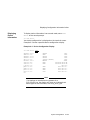
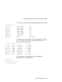
DEC 4000 AXP (all configurations with RF/RZ73, RZ26 drives) acoustics —
declared values per ISO 9296 and ISO 7779 (June 22, 1992):
Idle
Operating
LwAd , B
LpAm , dBA
(Bystander Positions)
6.6
6.7
48
49
Current values for specific configurations are available from Digital
representatives. 1 B = 10 dBA.
Schallemissionswerte — Werteangaben nach ISO 9296 und ISO 7779
/DIN45635-19:
Leerlauf
Betrieb
Schalleistungspegel
LwAd , B
Schalldruckpegel
LpAm , dBA
(Zuschauerpositionen)
6.6
6.7
48
49
Aktuelle Werte für spezielle Ausrüstungsstufen sind über die Digital Equipment
Vertretungen erhältlich. 1 B = 10 dBA.
Recycled Paper
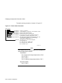
Contents
Preface . . . . . . . . . . . . . . . . . . . . . . . . . . . . . . . . . . . . . . . . . . . . . . . . . . . . .
xix
1 Getting Started
Introducing the DEC 4000 AXP Server
The New Arrival . . . . . . . . . . . . . .
In This Chapter . . . . . . . . . . . . . . .
Components and Controls . . . . . . . . . .
Gaining Access to Controls . . . . . . .
Opening System Doors . . . . . . . . . .
Components: Front of System . . . .
Operator Control Panel . . . . . . . . .
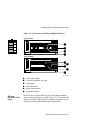
Components: Rear of System . . . . .
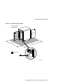
Card Cage . . . . . . . . . . . . . . . . . . .
Power Subsystem . . . . . . . . . . . . . .
System Operation: Overview . . . . . . . .
Two Levels of Operation . . . . . . . . .
Console Mode . . . . . . . . . . . . . . . . .
Operating System Mode . . . . . . . . .
Starting the System . . . . . . . . . . . . . . .
Before You Start the System . . . . .
When to Start the System . . . . . . .
Overview of the Task . . . . . . . . . . .
Power Up External Devices . . . . . .
Power Up the System . . . . . . . . . . .
If You Have a Problem . . . . . . . . . .
Set Environment Variables . . . . . .
Boot Operating System Software . .
Using the Operator Control Panel . . . .
Before You Use the Control Panel .
Overview . . . . . . . . . . . . . . . . . . . .
Invoke Console Mode . . . . . . . . . . .
Reset the System . . . . . . . . . . . . . .
.
.
.
.
.
.
.
.
.
.
.
.
.
.
.
.
.
.
.
.
.
.
.
.
.
.
.
.
.
.
.
.
.
.
.
.
.
.
.
.
.
.
.
.
.
.
.
.
.
.
.
.
.
.
.
.
.
.
.
.
.
.
.
.
.
.
.
.
.
.
.
.
.
.
.
.
.
.
.
.
.
.
.
.
.
.
.
.
.
.
.
.
.
.
.
.
.
.
.
.
.
.
.
.
.
.
.
.
.
.
.
.
.
.
.
.
.
.
.
.
.
.
.
.
.
.
.
.
.
.
.
.
.
.
.
.
.
.
.
.
.
.
.
.
.
.
.
.
.
.
.
.
.
.
.
.
.
.
.
.
.
.
.
.
.
.
.
.
.
.
.
.
.
.
.
.
.
.
.
.
.
.
.
.
.
.
.
.
.
.
.
.
.
.
.
.
.
.
.
.
.
.
.
.
.
.
.
.
.
.
.
.
.
.
.
.
.
.
.
.
.
.
.
.
.
.
.
.
.
.
.
.
.
.
.
.
.
.
.
.
.
.
.
.
.
.
.
.
.
.
.
.
.
.
.
.
.
.
.
.
.
.
.
.
.
.
.
.
.
.
.
.
.
.
.
.
.
.
.
.
.
.
.
.
.
.
.
.
.
.
.
.
.
.
.
.
.
.
.
.
.
.
.
.
.
.
.
.
.
.
.
.
.
.
.
.
.
.
.
.
.
.
.
.
.
.
.
.
.
.
.
.
.
.
.
.
.
.
.
.
.
.
.
.
.
.
.
.
.
.
.
.
.
.
.
.
.
.
.
.
.
.
.
.
.
.
.
.
.
.
.
.
.
.
.
.
.
.
.
.
.
.
.
.
.
.
.
.
.
.
.
.
.
.
.
.
.
.
.
.
.
.
.
.
.
.
.
.
.
.
.
.
.
.
.
.
.
.
.
.
.
.
.
.
.
.
.
.
.
.
.
.
.
.
.
.
.
.
.
.
.
.
.
.
.
.
.
.
.
.
.
.
.
.
.
.
.
.
.
.
.
.
.
.
.
.
.
.
.
.
.
.
.
.
.
.
.
.
.
.
.
.
.
.
.
.
.
.
.
.
.
.
.
.
.
.
.
.
.
.
.
.
.
.
.
.
.
.
.
.
.
.
.
.
.
.
.
.
.
.
.
.
.
.
.
.
.
.
.
.
.
.
.
.
.
.
.
.
.
.
.
.
.
.
.
.
.
.
.
.
.
.
.
.
.
.
.
.
.
.
.
.
.
.
.
.
.
.
.
.
.
.
.
.
.
.
.
.
.
.
1–1
1–1
1–2
1–2
1–2
1–4
1–5
1–6
1–7
1–8
1–9
1–10
1–10
1–10
1–10
1–11
1–11
1–11
1–11
1–11
1–12
1–13
1–14
1–15
1–17
1–17
1–17
1–18
1–20
vii
Power Down the System .
Monitor Self-Test Results
Help . . . . . . . . . . . . . . . . . . . .
Getting Help . . . . . . . . . .
References . . . . . . . . . . . . . . .
.
.
.
.
.
.
.
.
.
.
.
.
.
.
.
.
.
.
.
.
.
.
.
.
.
.
.
.
.
.
.
.
.
.
.
.
.
.
.
.
.
.
.
.
.
.
.
.
.
.
.
.
.
.
.
.
.
.
.
.
.
.
.
.
.
.
.
.
.
.
.
.
.
.
.
.
.
.
.
.
.
.
.
.
.
.
.
.
.
.
.
.
.
.
.
.
.
.
.
.
.
.
.
.
.
.
.
.
.
.
.
.
.
.
.
.
.
.
.
.
.
.
.
.
.
.
.
.
.
.
.
.
.
.
.
1–21
1–21
1–22
1–22
1–23
Chapter Description . . . . . . . . . . . . . . . . . . . . . . . . . . . .
What Is the Console Subsystem? . . . . . . . . . . . . . . .
In This Chapter . . . . . . . . . . . . . . . . . . . . . . . . . . . .
Components of the Console Subsystem . . . . . . . . . . . . .
Console Subsystem . . . . . . . . . . . . . . . . . . . . . . . . . .
Running the Console Program: Invoking Console Mode
Overview . . . . . . . . . . . . . . . . . . . . . . . . . . . . . . . . .
From the Console Terminal . . . . . . . . . . . . . . . . . . .
From the Auxiliary Serial Port . . . . . . . . . . . . . . . .
From Across the Ethernet . . . . . . . . . . . . . . . . . . . .
Console Mode User Interface . . . . . . . . . . . . . . . . . . . . .
Console Prompt . . . . . . . . . . . . . . . . . . . . . . . . . . . .
Keyboard Characters . . . . . . . . . . . . . . . . . . . . . . . .
Control Characters . . . . . . . . . . . . . . . . . . . . . . . . . .
.
.
.
.
.
.
.
.
.
.
.
.
.
.
.
.
.
.
.
.
.
.
.
.
.
.
.
.
.
.
.
.
.
.
.
.
.
.
.
.
.
.
.
.
.
.
.
.
.
.
.
.
.
.
.
.
.
.
.
.
.
.
.
.
.
.
.
.
.
.
.
.
.
.
.
.
.
.
.
.
.
.
.
.
.
.
.
.
.
.
.
.
.
.
.
.
.
.
2–1
2–1
2–1
2–2
2–2
2–4
2–4
2–4
2–5
2–5
2–6
2–6
2–6
2–8
.
.
.
.
.
.
.
.
.
.
.
.
.
.
.
.
.
.
.
.
.
.
.
.
.
.
.
.
.
.
.
.
.
.
.
.
.
.
.
.
.
.
.
.
.
.
.
.
.
.
.
.
.
.
.
.
.
.
.
.
.
.
.
.
.
.
.
.
.
.
.
.
.
.
.
.
.
.
.
.
.
.
.
.
.
.
.
.
.
.
.
.
.
.
.
.
.
.
.
.
.
.
.
.
.
.
.
.
.
.
.
.
.
.
.
.
.
.
.
.
.
.
.
.
.
.
3–1
3–1
3–1
3–1
3–2
3–3
3–3
3–3
3–3
3–4
3–5
3–5
3–5
3–5
3–6
3–6
3–6
3–7
2 Console Subsystem
3 Console Commands
What Are the Console Commands? . . . . . . . . . .
In This Chapter . . . . . . . . . . . . . . . . . . . . . .
Levels of Commands . . . . . . . . . . . . . . . . . .
Basic Commands . . . . . . . . . . . . . . . . . . . . .
Comprehensive Commands . . . . . . . . . . . . .
Entering Console Commands . . . . . . . . . . . . . . .
New Console Commands . . . . . . . . . . . . . . .
Console Command Format . . . . . . . . . . . . . .
Online Help . . . . . . . . . . . . . . . . . . . . . . . . .
How to Display Output One Page at a Time
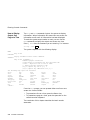
boot . . . . . . . . . . . . . . . . . . . . . . . . . . . . . . . . . .
Synopsis . . . . . . . . . . . . . . . . . . . . . . . . . . . .
Description . . . . . . . . . . . . . . . . . . . . . . . . . .
Parameters . . . . . . . . . . . . . . . . . . . . . . . . .
Flags . . . . . . . . . . . . . . . . . . . . . . . . . . . . . .
Examples . . . . . . . . . . . . . . . . . . . . . . . . . . .
Reference . . . . . . . . . . . . . . . . . . . . . . . . . . .
cdp . . . . . . . . . . . . . . . . . . . . . . . . . . . . . . . . . .
viii
.
.
.
.
.
.
.
.
.
.
.
.
.
.
.
.
.
.
.
.
.
.
.
.
.
.
.
.
.
.
.
.
.
.
.
.
.
.
.
.
.
.
.
.
.
.
.
.
.
.
.
.
.
.
.
.
.
.
.
.
.
.
.
.
.
.
.
.
.
.
.
.
.
.
.
.
.
.
.
.
.
.
.
.
.
.
.
.
.
.
.
.
.
.
.
.
.
.
.
.
.
.
.
.
.
.
.
.
Synopsis . . . . . . . . . . . .
Description . . . . . . . . . .
Parameters . . . . . . . . .
Flags . . . . . . . . . . . . . .
Examples . . . . . . . . . . .
Reference . . . . . . . . . . .
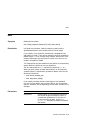
continue . . . . . . . . . . . . . . .
Synopsis . . . . . . . . . . . .
Description . . . . . . . . . .
Examples . . . . . . . . . . .
date . . . . . . . . . . . . . . . . . .
Synopsis . . . . . . . . . . . .
Description . . . . . . . . . .
Parameters . . . . . . . . .
Examples . . . . . . . . . . .
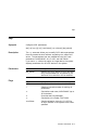
help or man . . . . . . . . . . . .
Synopsis . . . . . . . . . . . .
Description . . . . . . . . . .
Parameters . . . . . . . . .
Examples . . . . . . . . . . .
init . . . . . . . . . . . . . . . . . . .
Synopsis . . . . . . . . . . . .
Description . . . . . . . . . .
Examples . . . . . . . . . . .
man . . . . . . . . . . . . . . . . . .
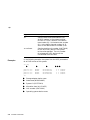
set . . . . . . . . . . . . . . . . . . .
Synopsis . . . . . . . . . . . .
Description . . . . . . . . . .
Parameters . . . . . . . . .
Flags . . . . . . . . . . . . . .
Environment Variables .
Examples . . . . . . . . . . .
Reference . . . . . . . . . . .
set host . . . . . . . . . . . . . . .
Synopsis . . . . . . . . . . . .
Description . . . . . . . . . .
Parameters . . . . . . . . .
Flags . . . . . . . . . . . . . .
Examples . . . . . . . . . . .
show . . . . . . . . . . . . . . . . . .
Synopsis . . . . . . . . . . . .
Description . . . . . . . . . .
Parameters . . . . . . . . .
.
.
.
.
.
.
.
.
.
.
.
.
.
.
.
.
.
.
.
.
.
.
.
.
.
.
.
.
.
.
.
.
.
.
.
.
.
.
.
.
.
.
.
.
.
.
.
.
.
.
.
.
.
.
.
.
.
.
.
.
.
.
.
.
.
.
.
.
.
.
.
.
.
.
.
.
.
.
.
.
.
.
.
.
.
.
.
.
.
.
.
.
.
.
.
.
.
.
.
.
.
.
.
.
.
.
.
.
.
.
.
.
.
.
.
.
.
.
.
.
.
.
.
.
.
.
.
.
.
.
.
.
.
.
.
.
.
.
.
.
.
.
.
.
.
.
.
.
.
.
.
.
.
.
.
.
.
.
.
.
.
.
.
.
.
.
.
.
.
.
.
.
.
.
.
.
.
.
.
.
.
.
.
.
.
.
.
.
.
.
.
.
.
.
.
.
.
.
.
.
.
.
.
.
.
.
.
.
.
.
.
.
.
.
.
.
.
.
.
.
.
.
.
.
.
.
.
.
.
.
.
.
.
.
.
.
.
.
.
.
.
.
.
.
.
.
.
.
.
.
.
.
.
.
.
.
.
.
.
.
.
.
.
.
.
.
.
.
.
.
.
.
.
.
.
.
.
.
.
.
.
.
.
.
.
.
.
.
.
.
.
.
.
.
.
.
.
.
.
.
.
.
.
.
.
.
.
.
.
.
.
.
.
.
.
.
.
.
.
.
.
.
.
.
.
.
.
.
.
.
.
.
.
.
.
.
.
.
.
.
.
.
.
.
.
.
.
.
.
.
.
.
.
.
.
.
.
.
.
.
.
.
.
.
.
.
.
.
.
.
.
.
.
.
.
.
.
.
.
.
.
.
.
.
.
.
.
.
.
.
.
.
.
.
.
.
.
.
.
.
.
.
.
.
.
.
.
.
.
.
.
.
.
.
.
.
.
.
.
.
.
.
.
.
.
.
.
.
.
.
.
.
.
.
.
.
.
.
.
.
.
.
.
.
.
.
.
.
.
.
.
.
.
.
.
.
.
.
.
.
.
.
.
.
.
.
.
.
.
.
.
.
.
.
.
.
.
.
.
.
.
.
.
.
.
.
.
.
.
.
.
.
.
.
.
.
.
.
.
.
.
.
.
.
.
.
.
.
.
.
.
.
.
.
.
.
.
.
.
.
.
.
.
.
.
.
.
.
.
.
.
.
.
.
.
.
.
.
.
.
.
.
.
.
.
.
.
.
.
.
.
.
.
.
.
.
.
.
.
.
.
.
.
.
.
.
.
.
.
.
.
.
.
.
.
.
.
.
.
.
.
.
.
.
.
.
.
.
.
.
.
.
.
.
.
.
.
.
.
.
.
.
.
.
.
.
.
.
.
.
.
.
.
.
.
.
.
.
.
.
.
.
.
.
.
.
.
.
.
.
.
.
.
.
.
.
.
.
.
.
.
.
.
.
.
.
.
.
.
.
.
.
.
.
.
.
.
.
.
.
.
.
.
.
.
.
.
.
.
.
.
.
.
.
.
.
.
.
.
.
.
.
.
.
.
.
.
.
.
.
.
.
.
.
.
.
.
.
.
.
.
.
.
.
.
.
.
.
.
.
.
.
.
.
.
.
.
.
.
.
.
.
.
.
.
.
.
.
.
.
.
.
.
.
.
.
.
.
.
.
.
.
.
.
.
.
.
.
.
.
.
.
.
.
.
.
.
.
.
.
.
.
.
.
.
.
.
.
.
.
.
.
.
.
.
.
.
.
.
.
.
.
.
.
.
.
.
.
.
.
.
.
.
.
.
.
.
.
.
.
.
.
.
.
.
.
.
.
.
.
.
.
.
.
.
.
.
.
.
.
.
.
.
.
.
.
.
.
.
.
.
.
.
.
.
.
.
.
.
.
.
.
.
.
.
.
.
.
.
.
.
.
.
.
.
.
.
.
.
.
.
.
.
.
.
.
.
.
.
.
.
.
.
.
.
.
.
.
.
.
.
.
.
.
.
.
.
.
.
.
.
.
.
.
.
.
.
.
.
.
.
.
.
.
.
.
.
.
.
.
.
.
.
.
.
.
.
.
.
.
.
.
.
.
.
.
.
.
.
.
.
.
.
.
.
.
.
.
.
.
.
.
.
.
.
.
.
.
.
.
.
.
.
.
.
.
.
.
.
.
.
.
.
.
.
.
.
.
.
.
.
.
.
.
.
.
.
.
.
.
.
.
.
.
.
.
.
.
.
.
.
.
.
.
.
.
.
.
.
.
.
.
.
.
.
.
.
.
.
.
.
.
.
.
.
.
.
.
.
.
.
.
.
.
.
.
.
.
.
.
.
.
.
.
.
.
.
.
.
.
.
.
.
.
.
.
.
.
.
.
.
.
.
.
.
.
.
.
.
.
.
.
.
.
.
.
.
.
.
.
.
.
.
.
.
.
.
.
.
.
.
.
.
.
.
.
.
.
.
.
.
.
.
.
.
.
.
.
.
.
.
.
.
.
.
.
.
.
.
.
.
.
.
.
.
.
.
.
.
.
.
.
.
.
.
.
.
.
.
.
.
.
.
.
.
.
.
.
.
.
.
.
.
.
.
.
.
.
.
.
.
.
.
.
.
.
.
.
.
.
.
.
.
.
.
.
.
.
.
.
.
.
.
.
.
.
.
.
.
.
.
.
.
.
.
.
.
.
.
.
.
.
.
.
.
.
.
.
.
.
.
.
.
.
.
.
.
.
.
.
.
.
.
.
.
.
.
.
.
.
.
.
.
.
.
.
.
.
.
.
.
.
.
.
.
.
.
.
.
.
.
.
.
.
.
.
.
3–7
3–7
3–7
3–7
3–8
3–9
3–10
3–10
3–10
3–10
3–11
3–11
3–11
3–11
3–12
3–13
3–13
3–13
3–13
3–13
3–14
3–14
3–14
3–14
3–15
3–16
3–16
3–16
3–16
3–16
3–16
3–18
3–18
3–19
3–19
3–19
3–19
3–19
3–20
3–21
3–21
3–21
3–21
ix
Environment Variables .
Examples . . . . . . . . . . .
Reference . . . . . . . . . . .
test . . . . . . . . . . . . . . . . . . .
Synopsis . . . . . . . . . . . .
Description . . . . . . . . . .
Examples . . . . . . . . . . .
References . . . . . . . . . . . . .
.
.
.
.
.
.
.
.
.
.
.
.
.
.
.
.
.
.
.
.
.
.
.
.
.
.
.
.
.
.
.
.
.
.
.
.
.
.
.
.
.
.
.
.
.
.
.
.
.
.
.
.
.
.
.
.
.
.
.
.
.
.
.
.
.
.
.
.
.
.
.
.
.
.
.
.
.
.
.
.
.
.
.
.
.
.
.
.
.
.
.
.
.
.
.
.
.
.
.
.
.
.
.
.
.
.
.
.
.
.
.
.
.
.
.
.
.
.
.
.
.
.
.
.
.
.
.
.
.
.
.
.
.
.
.
.
.
.
.
.
.
.
.
.
.
.
.
.
.
.
.
.
.
.
.
.
.
.
.
.
.
.
.
.
.
.
.
.
.
.
.
.
.
.
.
.
.
.
.
.
.
.
.
.
.
.
.
.
.
.
.
.
.
.
.
.
.
.
.
.
.
.
.
.
.
.
.
.
.
.
.
.
.
.
.
.
.
.
.
.
.
.
.
.
.
.
.
.
.
.
.
.
3–22
3–23
3–23
3–24
3–24
3–24
3–24
3–25
Chapter Description . . . . . . . . . . . . . . . . . . . . . . . . . . . . . .
What Is an Environment Variable? . . . . . . . . . . . . . . .
In This Chapter . . . . . . . . . . . . . . . . . . . . . . . . . . . . . .
Overview: Do I Need to Set Environment Variables? . . . . .
Deciding to Set Environment Variables . . . . . . . . . . . .
What Variables Can I Set? . . . . . . . . . . . . . . . . . . . . . .
Displaying Current Environment Variables . . . . . . . . .
Before You Begin . . . . . . . . . . . . . . . . . . . . . . . . . . . . . . . .
Preliminary Actions . . . . . . . . . . . . . . . . . . . . . . . . . . .
Changing the Default Startup Action (auto_action) . . . . . .
Default Startup Actions . . . . . . . . . . . . . . . . . . . . . . . .
Your System’s Current Startup Action . . . . . . . . . . . . .
Choosing ‘‘Halt’’ . . . . . . . . . . . . . . . . . . . . . . . . . . . . . .
Choosing ‘‘Boot’’ . . . . . . . . . . . . . . . . . . . . . . . . . . . . . .
Choosing ‘‘Restart’’ . . . . . . . . . . . . . . . . . . . . . . . . . . . .
Set the Default Startup Action . . . . . . . . . . . . . . . . . .
Undo the Setting . . . . . . . . . . . . . . . . . . . . . . . . . . . . .
Setting or Changing the Default Boot Device (bootdef_dev)
Default Boot Device . . . . . . . . . . . . . . . . . . . . . . . . . . .
Why Set the Default Boot Device? . . . . . . . . . . . . . . . .
Your System’s Current Default Boot Device . . . . . . . . .
Which One Is the Boot Device? . . . . . . . . . . . . . . . . . .
Preliminary Considerations . . . . . . . . . . . . . . . . . . . . .
Set or Change the Default Boot Device . . . . . . . . . . . .
Undo the Setting . . . . . . . . . . . . . . . . . . . . . . . . . . . . .
Setting Boot Flags (boot_osflags) . . . . . . . . . . . . . . . . . . . .
What Are Boot Flags? . . . . . . . . . . . . . . . . . . . . . . . . .
Boot Flags Settings for OpenVMS AXP Systems . . . . .
Boot Flags Settings for DEC OSF/1 AXP Systems . . . .
Your System’s Current Default Boot Flags . . . . . . . . . .
When to Set Boot Flags . . . . . . . . . . . . . . . . . . . . . . . .
Set Boot Flags . . . . . . . . . . . . . . . . . . . . . . . . . . . . . . .
.
.
.
.
.
.
.
.
.
.
.
.
.
.
.
.
.
.
.
.
.
.
.
.
.
.
.
.
.
.
.
.
.
.
.
.
.
.
.
.
.
.
.
.
.
.
.
.
.
.
.
.
.
.
.
.
.
.
.
.
.
.
.
.
.
.
.
.
.
.
.
.
.
.
.
.
.
.
.
.
.
.
.
.
.
.
.
.
.
.
.
.
.
.
.
.
.
.
.
.
.
.
.
.
.
.
.
.
.
.
.
.
.
.
.
.
.
.
.
.
.
.
.
.
.
.
.
.
.
.
.
.
.
.
.
.
.
.
.
.
.
.
.
.
.
.
.
.
.
.
.
.
.
.
.
.
.
.
.
.
4–1
4–1
4–1
4–2
4–2
4–2
4–2
4–4
4–4
4–4
4–4
4–5
4–5
4–5
4–5
4–6
4–6
4–7
4–7
4–7
4–7
4–7
4–8
4–9
4–9
4–10
4–10
4–10
4–12
4–12
4–12
4–13
4 Setting Environment Variables
x
Setting the Language (language) . . . . . . . . . . . . . . . . . . .
Do I Need to Set the Language? . . . . . . . . . . . . . . . .
Possible Settings . . . . . . . . . . . . . . . . . . . . . . . . . . . .
Your System’s Current Language . . . . . . . . . . . . . . . .
Change the Language . . . . . . . . . . . . . . . . . . . . . . . .
Changing the Baud Rate (tta0_baud and tta1_baud) . . . .
Which Baud Rates Can I Change? . . . . . . . . . . . . . . .
Displaying the Current Baud Rates . . . . . . . . . . . . . .
Change the Baud Rate . . . . . . . . . . . . . . . . . . . . . . . .
Enabling Halt Key Functions (tta0_halts and tta1_halts)
Why Enable Halt Key Functions? . . . . . . . . . . . . . . .
Possible Settings . . . . . . . . . . . . . . . . . . . . . . . . . . . .
Your System’s Current Halt Key Settings . . . . . . . . .
Set or Change the Halt Key Functions . . . . . . . . . . .
When You Have Finished Setting Variables . . . . . . . . . . .
Reboot the System . . . . . . . . . . . . . . . . . . . . . . . . . . .
.
.
.
.
.
.
.
.
.
.
.
.
.
.
.
.
.
.
.
.
.
.
.
.
.
.
.
.
.
.
.
.
.
.
.
.
.
.
.
.
.
.
.
.
.
.
.
.
.
.
.
.
.
.
.
.
.
.
.
.
.
.
.
.
.
.
.
.
.
.
.
.
.
.
.
.
.
.
.
.
.
.
.
.
.
.
.
.
.
.
.
.
.
.
.
.
4–14
4–14
4–14
4–14
4–15
4–15
4–15
4–16
4–17
4–18
4–18
4–18
4–18
4–19
4–19
4–19
Chapter Description . . . . . . . . . . . . . . . . . . . . . . . . . . . . . .
Overview . . . . . . . . . . . . . . . . . . . . . . . . . . . . . . . . . . .
In This Chapter . . . . . . . . . . . . . . . . . . . . . . . . . . . . . .
For Additional Information . . . . . . . . . . . . . . . . . . . . .
DEC 4000 AXP Mass Storage Devices and Compartments
Identifying Mass Storage Compartments . . . . . . . . . . .
Operating DEC 4000 AXP Mass Storage Devices . . . . . . . .
Before You Operate Mass Storage Devices . . . . . . . . . .
Operating DEC 4000 AXP Devices . . . . . . . . . . . . . . . .
Operating RZ- and RF-Series Disk Drives . . . . . . . . . . . . .
RZ- and RF-Series Description . . . . . . . . . . . . . . . . . . .
Fast SCSI . . . . . . . . . . . . . . . . . . . . . . . . . . . . . . . . . . .
RZ- and RF-Series Fault Light . . . . . . . . . . . . . . . . . . .
Write-Protecting an RZ- or RF-Series Disk . . . . . . . . .
Operating the RRD42 Compact Disc Drive . . . . . . . . . . . .
RRD42 Description . . . . . . . . . . . . . . . . . . . . . . . . . . .
Inserting a Compact Disc . . . . . . . . . . . . . . . . . . . . . .
Removing a Compact Disc . . . . . . . . . . . . . . . . . . . . . .
RRD42 Light . . . . . . . . . . . . . . . . . . . . . . . . . . . . . . . .
Operating the TLZ06 Tape Drive . . . . . . . . . . . . . . . . . . . .
TLZ06 Description . . . . . . . . . . . . . . . . . . . . . . . . . . . .
Compatible Tapes . . . . . . . . . . . . . . . . . . . . . . . . . . . . .
Inserting a Tape into the TLZ06 . . . . . . . . . . . . . . . . .
Removing a Tape from the TLZ06 . . . . . . . . . . . . . . . .
.
.
.
.
.
.
.
.
.
.
.
.
.
.
.
.
.
.
.
.
.
.
.
.
.
.
.
.
.
.
.
.
.
.
.
.
.
.
.
.
.
.
.
.
.
.
.
.
.
.
.
.
.
.
.
.
.
.
.
.
.
.
.
.
.
.
.
.
.
.
.
.
.
.
.
.
.
.
.
.
.
.
.
.
.
.
.
.
.
.
.
.
.
.
.
.
.
.
.
.
.
.
.
.
.
.
.
.
.
.
.
.
.
.
.
.
.
.
.
.
5–1
5–1
5–1
5–1
5–2
5–2
5–2
5–2
5–4
5–5
5–5
5–5
5–7
5–8
5–12
5–12
5–14
5–14
5–14
5–16
5–16
5–16
5–18
5–18
5 Operating Mass Storage Devices
xi
TLZ06 Lights . . . . . . . . . . . . . . . . . . . . . . .
Operating the TZ85 Tape Drive . . . . . . . . . . . .
TZ85 Description . . . . . . . . . . . . . . . . . . . .
Compatible Tapes . . . . . . . . . . . . . . . . . . . .
Inserting a Tape into the TZ85 . . . . . . . . .
Removing a Tape from the TZ85 . . . . . . . .
TZ85 Lights . . . . . . . . . . . . . . . . . . . . . . . .
Operating the TZ30 Tape Drive . . . . . . . . . . . .
TZ30 Description . . . . . . . . . . . . . . . . . . . .
Compatible Tapes . . . . . . . . . . . . . . . . . . . .
Inserting a Tape into the TZ30 . . . . . . . . .
Remove Tapes Before Power-Down . . . . . .
Removing a Tape from the TZ30 . . . . . . . .
TZ30 Lights . . . . . . . . . . . . . . . . . . . . . . . .
Maintaining Mass Storage Media and Devices .
Task Overview . . . . . . . . . . . . . . . . . . . . . .
Selecting a Media Write Setting . . . . . . . . .
For More Information . . . . . . . . . . . . . . . .
Labeling Removable Media . . . . . . . . . . . .
Handling Media . . . . . . . . . . . . . . . . . . . . .
Handling and Storing Discs and Caddies . .
Handling and Storing Tapes . . . . . . . . . . .
Cleaning the TLZ06 . . . . . . . . . . . . . . . . . .
Cleaning the TZ30 . . . . . . . . . . . . . . . . . . .
Cleaning the TZ85 . . . . . . . . . . . . . . . . . . .
References . . . . . . . . . . . . . . . . . . . . . . . . . . . .
.
.
.
.
.
.
.
.
.
.
.
.
.
.
.
.
.
.
.
.
.
.
.
.
.
.
.
.
.
.
.
.
.
.
.
.
.
.
.
.
.
.
.
.
.
.
.
.
.
.
.
.
.
.
.
.
.
.
.
.
.
.
.
.
.
.
.
.
.
.
.
.
.
.
.
.
.
.
.
.
.
.
.
.
.
.
.
.
.
.
.
.
.
.
.
.
.
.
.
.
.
.
.
.
.
.
.
.
.
.
.
.
.
.
.
.
.
.
.
.
.
.
.
.
.
.
.
.
.
.
.
.
.
.
.
.
.
.
.
.
.
.
.
.
.
.
.
.
.
.
.
.
.
.
.
.
.
.
.
.
.
.
.
.
.
.
.
.
.
.
.
.
.
.
.
.
.
.
.
.
.
.
.
.
.
.
.
.
.
.
.
.
.
.
.
.
.
.
.
.
.
.
.
.
.
.
.
.
.
.
.
.
.
.
.
.
.
.
.
.
.
.
.
.
.
.
.
.
.
.
.
.
.
.
.
.
.
.
.
.
.
.
.
.
.
.
.
.
.
.
.
.
.
.
.
.
.
.
.
.
.
.
.
.
.
.
.
.
.
.
.
.
.
.
.
.
.
.
.
.
.
.
.
.
.
.
.
.
.
.
.
.
.
.
.
.
.
.
.
.
.
.
.
.
.
.
.
.
.
.
.
.
.
.
.
.
.
.
.
.
.
.
.
.
.
.
.
.
.
.
.
.
.
.
.
.
.
.
.
.
.
.
.
.
.
.
.
.
.
.
.
.
.
.
.
.
.
.
.
.
.
.
.
.
5–20
5–22
5–22
5–22
5–24
5–26
5–28
5–29
5–29
5–29
5–32
5–34
5–34
5–36
5–37
5–37
5–37
5–37
5–38
5–38
5–38
5–39
5–40
5–41
5–41
5–42
.
.
.
.
.
.
.
.
.
.
.
.
.
.
.
.
.
.
.
.
.
.
.
.
.
.
.
.
.
.
.
.
.
.
.
.
.
.
.
.
.
.
.
.
.
.
.
.
.
.
.
.
.
.
.
.
.
.
.
.
.
.
.
.
.
.
.
.
.
.
.
.
.
.
.
.
.
.
.
.
.
.
.
.
.
.
.
.
.
.
.
.
.
.
.
.
.
.
.
.
.
.
.
.
.
.
.
.
.
.
.
.
.
.
.
.
.
.
.
.
.
.
.
.
.
.
.
.
.
.
.
.
.
.
.
.
.
.
.
.
.
.
.
.
.
.
.
.
.
.
.
.
.
.
.
.
.
.
.
.
.
.
.
.
.
.
.
.
.
.
.
.
.
.
.
.
.
.
.
.
.
.
.
.
.
.
.
.
.
.
.
.
.
.
.
.
6–1
6–1
6–1
6–2
6–2
6–2
6–4
6–4
6–4
6–4
6–5
6–6
6–6
6–6
6 System Configuration
Chapter Description . . . . . . . . . . . .
Introduction . . . . . . . . . . . . . . .
In This Chapter . . . . . . . . . . . .
Identifying Your Configuration . . . .
Overview . . . . . . . . . . . . . . . . .
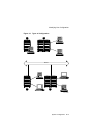
Types of Configurations . . . . . .
Special Configurations . . . . . . . . . .
Overview . . . . . . . . . . . . . . . . .
Dual CPU Systems . . . . . . . . .
DSSI VMSCluster . . . . . . . . . .
Benefits of a DSSI VMScluster
Identifying System Options . . . . . .
Specifics of Your Configuration .
System Modules . . . . . . . . . . . .
xii
.
.
.
.
.
.
.
.
.
.
.
.
.
.
.
.
.
.
.
.
.
.
.
.
.
.
.
.
.
.
.
.
.
.
.
.
.
.
.
.
.
.
.
.
.
.
.
.
.
.
.
.
.
.
.
.
.
.
.
.
.
.
.
.
.
.
.
.
.
.
.
.
.
.
.
.
.
.
.
.
.
.
.
.
.
.
.
.
.
.
.
.
.
.
.
.
.
.
.
.
.
.
.
.
.
.
.
.
.
.
.
.
.
.
.
.
.
.
.
.
.
.
.
.
.
.
Mass Storage Devices . . . . . . . . . . . . . . . . . . . . . . . . . . .
External Mass Storage Devices . . . . . . . . . . . . . . . . . . .
Network Devices . . . . . . . . . . . . . . . . . . . . . . . . . . . . . .
Identifying Mass Storage Devices . . . . . . . . . . . . . . . . . . . .
DSSI and SCSI Devices . . . . . . . . . . . . . . . . . . . . . . . . .
Buses Associated with Each Compartment . . . . . . . . . .
Drive IDs . . . . . . . . . . . . . . . . . . . . . . . . . . . . . . . . . . . .
Determining a Drive’s Address . . . . . . . . . . . . . . . . . . . .
Displaying Configuration Information Online . . . . . . . . . . .
Overview . . . . . . . . . . . . . . . . . . . . . . . . . . . . . . . . . . . .
Displaying System Configuration . . . . . . . . . . . . . . . . .
Displaying Memory Information . . . . . . . . . . . . . . . . . .
Displaying Device Information . . . . . . . . . . . . . . . . . . . .
Displaying Console Program Version . . . . . . . . . . . . . . .
Displaying PALcode Version . . . . . . . . . . . . . . . . . . . . . .
Planning a Change to Your Configuration . . . . . . . . . . . . . .
Perform Pre-Upgrade Tasks . . . . . . . . . . . . . . . . . . . . . .
Perform Post-Upgrade Tasks . . . . . . . . . . . . . . . . . . . . .
Adding Third-Party Devices . . . . . . . . . . . . . . . . . . . . . .
Connecting Additional Devices to Your System . . . . . . . . . .
Bus Expansion Ports . . . . . . . . . . . . . . . . . . . . . . . . . . .
Extending a Fast SCSI Bus . . . . . . . . . . . . . . . . . . . . . .
Connecting Additional Devices: Rules . . . . . . . . . . . . . .
Terminating and Extending a Bus . . . . . . . . . . . . . . . .
Terminating an Extended Bus . . . . . . . . . . . . . . . . . . . .
Changing Drive ID Numbers . . . . . . . . . . . . . . . . . . . . . . . .
When to Change Drive ID Numbers . . . . . . . . . . . . . . .
Changing a Drive ID: Rules . . . . . . . . . . . . . . . . . . . . . .
Changing a Drive ID Plug . . . . . . . . . . . . . . . . . . . . . . .
Setting and Examining Parameters for DSSI Devices . . . . .
When to Change DSSI Device Parameters . . . . . . . . . . .
Changing DSSI Device Parameters: Rules . . . . . . . . . .
Using cdp and show device du pu Commands . . . . . . . .
show device du pu . . . . . . . . . . . . . . . . . . . . . . . . . . . . .
cdp . . . . . . . . . . . . . . . . . . . . . . . . . . . . . . . . . . . . . . . . .
DSSI Device Parameters: Definitions and Function . . .
DSSI Device Parameter Descriptions . . . . . . . . . . . . . . .
How OpenVMS AXP Uses the DSSI Device Parameters
Example: Modifying DSSI Device Parameters . . . . . . . .
Using the Power Control Bus with a Storage Expander . . . .
Power Control Bus for Expanded Systems . . . . . . . . . . .
References . . . . . . . . . . . . . . . . . . . . . . . . . . . . . . . . . . . . . .
.
.
.
.
.
.
.
.
.
.
.
.
.
.
.
.
.
.
.
.
.
.
.
.
.
.
.
.
.
.
.
.
.
.
.
.
.
.
.
.
.
.
...
...
...
...
...
...
...
...
...
...
...
...
...
...
...
...
...
...
...
...
...
...
...
...
...
...
...
...
...
...
...
...
...
...
...
...
...
...
...
...
...
...
6–6
6–7
6–7
6–7
6–7
6–8
6–8
6–8
6–10
6–10
6–10
6–12
6–13
6–15
6–15
6–16
6–16
6–17
6–17
6–18
6–18
6–18
6–18
6–20
6–20
6–22
6–22
6–22
6–23
6–24
6–24
6–24
6–24
6–25
6–26
6–26
6–27
6–28
6–29
6–32
6–32
6–33
xiii
7 Learning More About Your System
Chapter Description . . . . . . . . . . . . . . . . . . . . .
Introduction . . . . . . . . . . . . . . . . . . . . . . . .
In This Chapter . . . . . . . . . . . . . . . . . . . . .
System Features . . . . . . . . . . . . . . . . . . . . . . .
What Makes It a DEC 4000 AXP System? .
Alpha AXP Architecture . . . . . . . . . . . . . . .
RISC Technology . . . . . . . . . . . . . . . . . . . .
Support of Multiple Operating Systems . . .
Integration with Existing Technology . . . . .
DSSI VMScluster Support . . . . . . . . . . . . .
Subsystems and Components . . . . . . . . . . . . . .
Overview . . . . . . . . . . . . . . . . . . . . . . . . . .
CPU Subsystem . . . . . . . . . . . . . . . . . . . . . . . .
Components . . . . . . . . . . . . . . . . . . . . . . . .
System Bus . . . . . . . . . . . . . . . . . . . . . . . .
Central Processing Unit . . . . . . . . . . . . . . .
Memory Module . . . . . . . . . . . . . . . . . . . . .
I/O Module . . . . . . . . . . . . . . . . . . . . . . . . .
Serial Control Bus . . . . . . . . . . . . . . . . . . .
Power Subsystem . . . . . . . . . . . . . . . . . . . . . . .
Components . . . . . . . . . . . . . . . . . . . . . . . .
Uninterruptible Power Supply (Optional) .
Storage Subsystem . . . . . . . . . . . . . . . . . . . . . .
Components . . . . . . . . . . . . . . . . . . . . . . . .
Mass Storage Adapters . . . . . . . . . . . . . . .
Mass Storage Devices . . . . . . . . . . . . . . . . .
Mass Storage Expansion Enclosure . . . . . .
Futurebus+ Subsystem . . . . . . . . . . . . . . . . . .
Overview . . . . . . . . . . . . . . . . . . . . . . . . . .
References . . . . . . . . . . . . . . . . . . . . . . . . . . . .
.
.
.
.
.
.
.
.
.
.
.
.
.
.
.
.
.
.
.
.
.
.
.
.
.
.
.
.
.
.
.
.
.
.
.
.
.
.
.
.
.
.
.
.
.
.
.
.
.
.
.
.
.
.
.
.
.
.
.
.
.
.
.
.
.
.
.
.
.
.
.
.
.
.
.
.
.
.
.
.
.
.
.
.
.
.
.
.
.
.
.
.
.
.
.
.
.
.
.
.
.
.
.
.
.
.
.
.
.
.
.
.
.
.
.
.
.
.
.
.
.
.
.
.
.
.
.
.
.
.
.
.
.
.
.
.
.
.
.
.
.
.
.
.
.
.
.
.
.
.
.
.
.
.
.
.
.
.
.
.
.
.
.
.
.
.
.
.
.
.
.
.
.
.
.
.
.
.
.
.
.
.
.
.
.
.
.
.
.
.
.
.
.
.
.
.
.
.
.
.
.
.
.
.
.
.
.
.
.
.
.
.
.
.
.
.
.
.
.
.
.
.
.
.
.
.
.
.
.
.
.
.
.
.
.
.
.
.
.
.
.
.
.
.
.
.
.
.
.
.
.
.
.
.
.
.
.
.
.
.
.
.
.
.
.
.
.
.
.
.
.
.
.
.
.
.
.
.
.
.
.
.
.
.
.
.
.
.
.
.
.
.
.
.
.
.
.
.
.
.
.
.
.
.
.
.
.
.
.
.
.
.
.
.
.
.
.
.
.
.
.
.
.
.
.
.
.
.
.
.
.
.
.
.
.
.
.
.
.
.
.
.
.
.
.
.
.
.
.
.
.
.
.
.
.
.
.
.
.
.
.
.
.
.
.
.
.
.
.
.
.
.
.
.
.
.
.
.
.
.
.
.
.
.
.
.
.
.
.
.
.
.
.
.
.
.
.
.
.
.
.
.
.
.
.
.
.
.
.
.
.
.
.
.
.
.
.
.
.
.
7–1
7–1
7–1
7–2
7–2
7–2
7–2
7–3
7–3
7–3
7–4
7–4
7–6
7–6
7–6
7–6
7–7
7–7
7–8
7–8
7–8
7–9
7–10
7–10
7–10
7–10
7–10
7–11
7–11
7–11
.
.
.
.
.
.
.
.
.
.
.
.
.
.
.
.
.
.
.
.
.
.
.
.
.
.
.
.
.
.
.
.
.
.
.
.
.
.
.
.
.
.
.
.
.
.
.
.
.
.
.
.
.
.
.
.
.
.
.
.
.
.
.
.
.
.
.
.
.
.
.
.
.
.
.
.
.
.
.
.
.
.
.
.
.
.
.
.
.
.
.
.
.
.
.
.
8–1
8–1
8–1
8–1
8–1
8–2
8–3
8–4
8 Care, Maintenance, and Exterior Customizations
Chapter Description . . . . . . . .
Introduction . . . . . . . . . . .
In This Chapter . . . . . . . .
Customizing the System Unit
Overview . . . . . . . . . . . . .
Locate Accessories . . . . . .
Label the System Name . .
Replace English-Language
xiv
......
......
......
......
......
......
......
Labels
.
.
.
.
.
.
.
.
.
.
.
.
.
.
.
.
.
.
.
.
.
.
.
.
.
.
.
.
.
.
.
.
.
.
.
.
.
.
.
.
.
.
.
.
.
.
.
.
.
.
.
.
.
.
.
.
.
.
.
.
.
.
.
.
.
.
.
.
.
.
.
.
Remove System Doors . . . .
Move the System . . . . . . . .
Antistatic Wrist Strap . . . .
Changing the Baud Rate . .
Maintaining the System . . . . .
Overview . . . . . . . . . . . . . .
Environmental Guidelines .
Liquid on the System Unit .
References . . . . . . . . . . . . . . . .
.
.
.
.
.
.
.
.
.
.
.
.
.
.
.
.
.
.
.
.
.
.
.
.
.
.
.
.
.
.
.
.
.
.
.
.
.
.
.
.
.
.
.
.
.
.
.
.
.
.
.
.
.
.
.
.
.
.
.
.
.
.
.
.
.
.
.
.
.
.
.
.
.
.
.
.
.
.
.
.
.
.
.
.
.
.
.
.
.
.
.
.
.
.
.
.
.
.
.
.
.
.
.
.
.
.
.
.
.
.
.
.
.
.
.
.
.
.
.
.
.
.
.
.
.
.
.
.
.
.
.
.
.
.
.
.
.
.
.
.
.
.
.
.
.
.
.
.
.
.
.
.
.
.
.
.
.
.
.
.
.
.
.
.
.
.
.
.
.
.
.
.
.
.
.
.
.
.
.
.
.
.
.
.
.
.
.
.
.
.
.
.
.
.
.
.
.
.
.
.
.
.
.
.
.
.
.
.
.
.
.
.
.
.
.
.
.
.
.
.
.
.
.
.
.
.
.
.
.
.
.
.
.
.
8–4
8–6
8–6
8–8
8–9
8–9
8–10
8–10
8–10
Chapter Description . . . . . . . . . . . . . . . . . . . .
Introduction . . . . . . . . . . . . . . . . . . . . . . .
In This Chapter . . . . . . . . . . . . . . . . . . . .
Before You Begin . . . . . . . . . . . . . . . . . . . . . .
Two Ways to Solve System Problems . . . .
Method to Identify Problems . . . . . . . . . .
Task Overview . . . . . . . . . . . . . . . . . . . . . . . .
Steps to Identifying a Problem . . . . . . . . .
Determining Type of Problem . . . . . . . . . . . .
Types of System Problems . . . . . . . . . . . .
Power Problems . . . . . . . . . . . . . . . . . . . . . . .
Power Problems . . . . . . . . . . . . . . . . . . . .
Power Supply Lights . . . . . . . . . . . . . . . .
Problems Getting to Console Mode . . . . . . . .
Pre-Console Mode Problems . . . . . . . . . . .
Operator Control Panel Lights . . . . . . . . .
Console Mode Problems . . . . . . . . . . . . . . . . .
Console Mode Problems . . . . . . . . . . . . . .
Boot Problems . . . . . . . . . . . . . . . . . . . . . . . .
Boot Problems . . . . . . . . . . . . . . . . . . . . .
Operating System Problems . . . . . . . . . . . . . .
Operating System Problems . . . . . . . . . . .
Mass Storage Problems . . . . . . . . . . . . . . . . .
Mass Storage Problems . . . . . . . . . . . . . .
RRD42 Disc Caddy Removal Problem . . .
Network Problems . . . . . . . . . . . . . . . . . . . . .
Ethernet Problems . . . . . . . . . . . . . . . . . .
Reporting Problems to Digital Services . . . . .
Digital Support Centers . . . . . . . . . . . . . .
How to Report Problems . . . . . . . . . . . . .
Digital Support Center Contact Numbers
.
.
.
.
.
.
.
.
.
.
.
.
.
.
.
.
.
.
.
.
.
.
.
.
.
.
.
.
.
.
.
.
.
.
.
.
.
.
.
.
.
.
.
.
.
.
.
.
.
.
.
.
.
.
.
.
.
.
.
.
.
.
.
.
.
.
.
.
.
.
.
.
.
.
.
.
.
.
.
.
.
.
.
.
.
.
.
.
.
.
.
.
.
.
.
.
.
.
.
.
.
.
.
.
.
.
.
.
.
.
.
.
.
.
.
.
.
.
.
.
.
.
.
.
.
.
.
.
.
.
.
.
.
.
.
.
.
.
.
.
.
.
.
.
.
.
.
.
.
.
.
.
.
.
.
.
.
.
.
.
.
.
.
.
.
.
.
.
.
.
.
.
.
.
.
.
.
.
.
.
.
.
.
.
.
.
.
.
.
.
.
.
.
.
.
.
.
.
.
.
.
.
.
.
.
.
.
.
.
.
.
.
.
.
.
.
.
.
.
.
.
.
.
.
.
.
.
.
.
.
.
.
.
.
.
.
.
.
.
.
.
.
.
.
.
.
.
.
.
.
.
.
.
.
.
.
.
.
.
.
.
.
.
.
.
.
.
.
.
.
.
.
.
.
.
.
.
.
.
.
.
.
.
.
.
.
.
.
.
.
.
.
.
.
.
.
.
.
.
.
.
.
.
.
.
.
.
.
.
.
.
.
.
.
.
.
.
.
.
.
.
.
.
.
.
.
.
.
.
.
.
.
.
.
.
.
.
.
.
.
.
.
.
.
.
.
.
.
.
.
.
.
.
.
.
.
.
.
.
.
.
.
.
.
.
.
.
.
.
.
.
.
.
.
.
.
.
.
.
.
.
.
.
.
.
.
.
.
.
.
.
.
.
.
.
.
.
.
.
.
.
.
.
.
.
.
.
.
.
.
.
.
.
.
.
.
.
.
.
.
.
.
.
.
.
.
.
.
.
.
.
.
.
.
.
.
.
.
.
.
.
.
.
.
.
.
.
.
.
.
.
.
.
.
.
.
.
.
.
.
.
.
.
.
.
9–1
9–1
9–1
9–2
9–2
9–2
9–3
9–3
9–4
9–4
9–5
9–5
9–5
9–8
9–8
9–9
9–11
9–11
9–12
9–12
9–13
9–13
9–14
9–14
9–16
9–17
9–17
9–18
9–18
9–18
9–18
9 Troubleshooting the System
xv
References . . . . . . . . . . . . . . . . . . . . . . . . . . . . . . . . . . . . . . . . . .
9–19
Glossary
Index
Examples
1–1
1–2
5–1
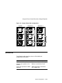
6–1
6–2
6–3
6–4
6–5
Booting OpenVMS AXP System Software Screen . . . . .
Booting DEC OSF/1 AXP System Software Screen . . .
Setting Hardware Write-Protection Through Firmware
System Configuration Display . . . . . . . . . . . . . . . . . . .
Memory Configuration Display . . . . . . . . . . . . . . . . . .
Device Configuration Display . . . . . . . . . . . . . . . . . . . .
Console Program Version . . . . . . . . . . . . . . . . . . . . . . .
PALcode Version . . . . . . . . . . . . . . . . . . . . . . . . . . . . . .
.
.
.
.
.
.
.
.
.
.
.
.
.
.
.
.
.
.
.
.
.
.
.
.
.
.
.
.
.
.
.
.
.
.
.
.
.
.
.
.
1–16
1–16
5–11
6–11
6–12
6–13
6–15
6–15
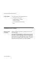
Location of System Keys . . . . . . . . . . . . . . . . .
Unlocking the System Door . . . . . . . . . . . . . . .
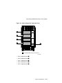
Front Components . . . . . . . . . . . . . . . . . . . . . .
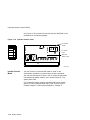
Operator Control Panel . . . . . . . . . . . . . . . . . .
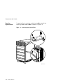
Rear Components . . . . . . . . . . . . . . . . . . . . . . .
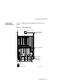
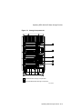
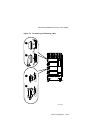
Card Cage . . . . . . . . . . . . . . . . . . . . . . . . . . . .
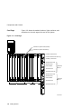
Power Subsystem . . . . . . . . . . . . . . . . . . . . . . .
System Power-Up Self-Test Screen . . . . . . . . . .
Sample Power-Up Configuration Screen . . . . . .
Operator Control Panel . . . . . . . . . . . . . . . . . .
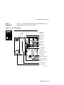
Console Subsystem . . . . . . . . . . . . . . . . . . . . . .
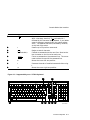
Supported Keys on a VT420 Keyboard . . . . . .
Storage Compartments . . . . . . . . . . . . . . . . . .
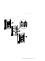
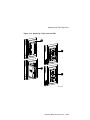
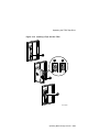
Front Panels for RZ-Series (SCSI) Disk Drives
Front Panels for RF-Series (DSSI) Disk Drives
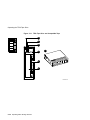
RRD42 Compact Disc Drive and Compact Disc
Inserting and Removing a Compact Disc . . . .
TLZ06 Drive and Compatible Tape . . . . . . . . .
.
.
.
.
.
.
.
.
.
.
.
.
.
.
.
.
.
.
.
.
.
.
.
.
.
.
.
.
.
.
.
.
.
.
.
.
.
.
.
.
.
.
.
.
.
.
.
.
.
.
.
.
.
.
.
.
.
.
.
.
.
.
.
.
.
.
.
.
.
.
.
.
.
.
.
.
.
.
.
.
.
.
.
.
.
.
.
.
.
.
1–3
1–4
1–5
1–6
1–7
1–8
1–9
1–13
1–14
1–18
2–3
2–7
5–3
5–6
5–7
5–13
5–15
5–17
Figures
1–1
1–2
1–3
1–4
1–5
1–6
1–7
1–8
1–9
1–10
2–1
2–2
5–1
5–2
5–3
5–4
5–5
5–6
xvi
.
.
.
.
.
.
.
.
.
.
.
.
.
.
.
.
.
.
.
.
.
.
.
.
.
.
.
.
.
.
.
.
.
.
.
.
.
.
.
.
.
.
.
.
.
.
.
.
.
.
.
.
.
.
.
.
.
.
.
.
.
.
.
.
.
.
.
.
.
.
.
.
.
.
.
.
.
.
.
.
.
.
.
.
.
.
.
.
.
.
.
.
.
.
.
.
.
.
.
.
.
.
.
.
.
.
.
.
5–7
5–8
5–9
5–10
5–11
5–12
5–13
5–14
5–15
6–1
6–2
6–3
6–4
6–5
6–6
6–7
6–8
6–9
7–1
8–1
8–2
8–3
8–4
8–5
9–1
9–2
9–3
Inserting and Removing a Tape: TLZ06 . . . . . . . . . . . .
TZ85 Drive and Compatible Tape . . . . . . . . . . . . . . . . .
Inserting a Tape into the TZ85 . . . . . . . . . . . . . . . . . .
Removing a Tape from the TZ85 . . . . . . . . . . . . . . . . .
TZ30 Tape Drive and Compatible Tape . . . . . . . . . . . .
Inserting a Tape into the TZ30 . . . . . . . . . . . . . . . . . .
Removing a Tape from the TZ30 . . . . . . . . . . . . . . . . .
Affixing Labels . . . . . . . . . . . . . . . . . . . . . . . . . . . . . . .
Caddy Shutter . . . . . . . . . . . . . . . . . . . . . . . . . . . . . . .
Types of Configurations . . . . . . . . . . . . . . . . . . . . . . . .
Drive Addresses . . . . . . . . . . . . . . . . . . . . . . . . . . . . . .
Device Name Convention . . . . . . . . . . . . . . . . . . . . . . .
Mass Storage Bus Expansion Ports . . . . . . . . . . . . . . .
Terminating and Extending a Bus . . . . . . . . . . . . . . . .
Inserting a Drive ID Plug . . . . . . . . . . . . . . . . . . . . . .
How OpenVMS AXP Sees Unit Numbers for DSSI
Devices . . . . . . . . . . . . . . . . . . . . . . . . . . . . . . . . . . . . .
Sample DSSI Buses for an Expanded DEC 4000 AXP
System . . . . . . . . . . . . . . . . . . . . . . . . . . . . . . . . . . . . .
Sample Power Bus Configuration . . . . . . . . . . . . . . . . .
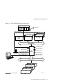
DEC 4000 AXP System Architecture . . . . . . . . . . . . . .
Accessories Box . . . . . . . . . . . . . . . . . . . . . . . . . . . . . .
Labeling the System Name . . . . . . . . . . . . . . . . . . . . .
Removing Front and Rear Doors . . . . . . . . . . . . . . . . .
Positioning the System . . . . . . . . . . . . . . . . . . . . . . . . .
Location of the Baud Rate Switch . . . . . . . . . . . . . . . .
Power Supply Lights . . . . . . . . . . . . . . . . . . . . . . . . . .
Operator Control Panel Lights . . . . . . . . . . . . . . . . . . .
Manually Removing a Disc Caddy . . . . . . . . . . . . . . . .
.
.
.
.
.
.
.
.
.
.
.
.
.
.
.
.
.
.
.
.
.
.
.
.
.
.
.
.
.
.
.
.
.
.
.
.
.
.
.
.
.
.
.
.
.
5–19
5–23
5–25
5–27
5–30
5–33
5–35
5–38
5–39
6–3
6–9
6–14
6–19
6–21
6–23
.....
6–29
.
.
.
.
.
.
.
.
.
.
.
.
.
.
.
.
.
.
.
.
.
.
6–30
6–33
7–5
8–2
8–3
8–5
8–7
8–9
9–6
9–10
9–16
.....
3–2
.....
.....
.....
3–3
4–3
5–4
.
.
.
.
.
.
.
.
.
.
.
.
.
.
.
.
.
.
.
.
.
.
.
.
.
.
.
.
.
.
.
.
.
.
.
.
.
.
.
.
.
.
.
.
.
.
.
.
.
.
.
.
.
.
.
.
.
.
.
.
.
.
.
Tables
3–1
3–2
4–1
5–1
Basic Console Commands . . . . . . . . . . . . . . . . . . . . . . .
Differences Between VAX and DEC 4000 AXP Console
Commands . . . . . . . . . . . . . . . . . . . . . . . . . . . . . . . . . .
Environment Variables . . . . . . . . . . . . . . . . . . . . . . . . .
Devices Supported by the DEC 4000 AXP . . . . . . . . . .
xvii
5–2
5–3
5–4
6–1
7–1
9–1
9–2
9–3
9–4
9–5
9–6
9–7
9–8
9–9
9–10
9–11
9–12
9–13
9–14
xviii
TLZ06 Light Summary . . . . . . . . . . . . . . . . . . . . .
TZ85 Light Summary . . . . . . . . . . . . . . . . . . . . . .
TZ30 Light Summary . . . . . . . . . . . . . . . . . . . . . .
Mass Storage Compartments and Devices . . . . . .
DEC 4000 AXP Subsystems . . . . . . . . . . . . . . . . .
How to Identify a Problem . . . . . . . . . . . . . . . . . .
Steps to Resolving Problems . . . . . . . . . . . . . . . .
Type of Problem . . . . . . . . . . . . . . . . . . . . . . . . . .
Diagnostic Flow for Power Problems . . . . . . . . . .
Interpreting Power Supply Lights . . . . . . . . . . . .
Diagnostic Flow for Problems Getting to Console .
Interpreting Operator Control Panel Lights . . . . .
Diagnostic Flow for Console Mode Problems . . . .
Diagnostic Flow for Boot Problems . . . . . . . . . . .
Diagnostic Flow for Operating System Errors . . .
Diagnostic Flow for Mass Storage Problems . . . .
Manual Removal of a Disc Caddy . . . . . . . . . . . .
Resolving Ethernet Problems . . . . . . . . . . . . . . . .
Telephone Numbers of Digital Support Centers . .
.
.
.
.
.
.
.
.
.
.
.
.
.
.
.
.
.
.
.
.
.
.
.
.
.
.
.
.
.
.
.
.
.
.
.
.
.
.
.
.
.
.
.
.
.
.
.
.
.
.
.
.
.
.
.
.
.
.
.
.
.
.
.
.
.
.
.
.
.
.
.
.
.
.
.
.
.
.
.
.
.
.
.
.
.
.
.
.
.
.
.
.
.
.
.
.
.
.
.
.
.
.
.
.
.
.
.
.
.
.
.
.
.
.
.
.
.
.
.
.
.
.
.
.
.
.
.
.
.
.
.
.
.
.
.
.
.
.
.
.
.
.
.
.
.
.
.
.
.
.
.
.
.
.
.
.
.
.
.
.
.
.
.
.
.
.
.
.
.
.
.
5–20
5–28
5–36
6–8
7–4
9–2
9–3
9–4
9–5
9–6
9–9
9–10
9–11
9–12
9–13
9–14
9–16
9–17
9–19
Preface
Purpose of This
Guide
This guide describes how to operate, troubleshoot, and maintain
the DEC 4000 AXP system.
Before You Use
This Guide
This guide assumes that you are ready to operate your system.
Before using this guide, you or a Digital service representative
should complete the following tasks:
Who Should
Use This Guide
•
Prepare your site so that it meets the requirements described
in the DEC 4000 Model 600 Series Site Preparation Checklist.
•
Install the system at your site.
If you have not . . .
Then . . .
Prepared your site
Refer to the DEC 4000 Model 600 Series
Site Preparation Checklist.
Installed the system
Have the system installed by a Digital
service representative, or, if you are a
qualified self-maintenance customer,
install the system yourself. Refer to
the DEC 4000 Model 600 Series Quick
Installation.
This book is for system managers and others who perform system
management tasks.
xix
Structure of
This Guide
Finding More
Information
xx
This guide contains information about how to use your system to
best advantage:
•
Chapter 1 introduces the system and describes basic system
management tasks.
•
Chapter 2 describes how to use the console mode
environment.
•
Chapter 3 describes the console commands.
•
Chapter 4 describes how to set environment variables.
•
Chapter 5 describes how to operate mass storage devices.
•
Chapter 6 describes how to identify your system
configuration and how to change your configuration.
•
Chapter 7 describes system features.
•
Chapter 8 describes how to maintain your system and
customize its exterior.
•
Chapter 9 explains how to identify and resolve problems that
prevent you from operating the system.
•
The Glossary contains technical terms that are used in this
book.
Occasionally, this guide will direct you to a different document.
The following two keys will help you identify and locate these
documents more easily.
•
On the front page of this guide, a map shows you the DEC
4000 AXP information products that are available.
•
The last page of each chapter shows you where to find more
information about the topics in that chapter.
Conventions
The following table lists conventions used in this guide.
Convention
Meaning
Return
A key name enclosed in a box indicates that you press that key.
Ctrl/x
Ctrl/x indicates that you hold down the Ctrl key while you
press another key, indicated here by x. In examples, this key
combination is enclosed in a box, for example, Ctrl/C .
bold type
In the online book (Bookreader), bold type in examples
indicates commands and other instructions that you enter
at the keyboard.
lowercase
Lowercase letters in commands indicate that commands can be
entered in uppercase or lowercase.
In some illustrations, small drawings of the DEC 4000 AXP
system appear in the left margin. Shaded areas help you locate
components on the front or back of the system.
Caution
Cautions provide information to prevent damage to equipment
or software.
[]
In command format descriptions, brackets indicate optional
elements.
console command
abbreviations
Console command abbreviations must be entered exactly as
shown.
boot
Console and operating system commands are shown in this
special typeface.
italic type
Italic type in console command sections indicates a variable.
<>
In console mode online help, angle brackets enclose a
placeholder for which you must specify a value.
{}
In command descriptions, braces containing items separated by
commas imply mutually exclusive items.
! "#...
In figures, labels a part of the figure. In text, refers to a
labeled part of a corresponding figure.
xxi
1
Getting Started
Introducing the DEC 4000 AXP Server
The New Arrival
Congratulations on the purchase of your new DEC 4000 AXP
system!
Getting Started 1–1
Getting Started
The DEC 4000 AXP system is a high-performance superserver
for multi-user environments.
Introducing the DEC 4000 AXP Server
In This Chapter
This chapter covers the following information:
•
Components and Controls
•
System Operation: Overview
•
Starting the System
•
Using the Operator Control Panel
•
Help
Components and Controls
Gaining Access
to Controls
System components and controls are located at the front and
rear of the system.
You access these system features by opening the front and rear
system doors. To open the doors, use one of two identical keys
that comes in a plastic bag taped to the top of the Accessories
Box that ships with your DEC 4000 AXP system. You can use
either key to unlock both the front and rear doors. Figure 1–1
shows the location of the keys in your system shipment.
1–2 Getting Started
Components and Controls
Figure 1–1 Location of System Keys
MLO-008861
Getting Started 1–3
Components and Controls
Opening
System Doors
!
To open the front or rear door, unlock the door
and pull the
upper right edge toward you
as shown in Figure 1–2.
"
Figure 1–2 Unlocking the System Door
1
2
MLO-007712
1–4 Getting Started
Components and Controls
Components:
Front of
System
Figure 1–3 shows the components on the front of the system.
Figure 1–3 Front Components
Air Plenum
DC On/Off Switch
A
Operator Control
Panel
B
C
D
E
Cable Guide
Base Unit,
Contains
Fans 3 and 4
Fixed-Media Mass Storage Compartments
Removable-Media Mass Storage Compartment
MLO-007714
Getting Started 1–5
Components and Controls
Operator
Control Panel
Figure 1–4 shows the operator control panel on the front of the
system.
Figure 1–4 Operator Control Panel
DC On/Off
Switch
DC Power
Light
Self-Test
Status Lights
Reset
Halt
6-1
3
2
1
MEM
0
0
1
CPU
I/O
MLO-008872
For information about mass storage controls, refer to devicespecific information in Chapter 5 of this guide.
1–6 Getting Started
Components and Controls
Components:
Rear of System
Figure 1–5 shows the major components at the rear of the
system.
Figure 1–5 Rear Components
Serial and Model
Number Label
AC Circuit Breaker
Cable Guide
Base Unit,
Contains
Fans 1 and 2
Card Cage
Power Subsystem
MLO-007715
Getting Started 1–7
Components and Controls
Figure 1–6 shows the module locations, lights, switches, and
connectors on the card cage at the rear of the system.
Card Cage
Figure 1–6 Card Cage
Futurebus+ Option Fault (Amber)
Futurebus+ Option OK (Green)
Console Terminal Port
Console Terminal Ground Lug
Auxilliary Serial Port
ThinWire Fuse OK
ThinWire Port
F1
Select Switch
Ethernet
Port 0
Thickwire Port
0
Thickwire Fuse OK
ThinWire Fuse OK
F2
F3
6
5
4
3
2
1
3
2
1
MEM
0
0
1
1
CPU
ThinWire Port
Select Switch
Ethernet
Port 1
Thickwire Port
Thickwire Fuse OK
F4
I/O
1–8 Getting Started
MLO-009366
Components and Controls
Power
Subsystem
Figure 1–7 shows the lights, switches, and connectors on the
power supply at the rear of the system.
Figure 1–7 Power Subsystem
FEU
PSC
DC5
DC3
AC Circuit
Breaker
FEU Failure
FEU OK
DC3 Failure
DC3 OK
DC5 Failure
DC5 OK
MO
SI
SO
Main Out
Secondary In
Secondary Out
PSC Failure
PSC OK
Overtemperature
Shutdown
Fan Failure
Disk Power Failure
Fault ID Display
UPS Signal Control
Port
AC Present
AC Power Port
MLO-009367
Getting Started 1–9
System Operation: Overview
System Operation: Overview
Two Levels of
Operation
Console Mode
The system can run in one of two environments:
•
Console mode
•
Operating system mode
In console mode, the system and the console terminal operate
under the control of the console subsystem. All user input is
passed to the console subsystem.
The system runs in console mode under two circumstances:
•
The system is powered up and operating system software has
not been booted
•
Operating system software has been shut down or has
crashed
Chapter 2 describes how to use the system in console mode.
Operating
System Mode
In operating system mode, the system and console terminal are
under control of the operating system. All user input is passed
to the operating system.
The system runs in operating system mode if the system
is powered up and operating system software is running
uninterrupted.
Once you complete the steps described in Starting the System,
your system will be running in operating system mode. Refer
to your operating system documentation for information about
using the system in operating system mode.
1–10 Getting Started
Starting the System
Starting the System
Before You
Start the
System
You start a system by bringing it from a powered-down state
to the point at which the operating system login banner is
displayed on the console terminal.
Before starting the system, you should be familiar with system
components, lights, and controls. Use the diagrams on previous
pages to familiarize yourself with these features.
When to Start
the System
Overview of the
Task
Your system may already be started:
•
If the operating system login banner or prompt is displayed
on your console terminal, the system is already started. Skip
this section and proceed to the next section in this chapter,
Using the Operator Control Panel.
•
If the console prompt (>>>) is displayed on your console
terminal, the system is in console mode. To finish starting
the system, set environment variables (described in
Chapter 4) and boot operating system software (described in
Boot Operating System Software, in this chapter).
Start the system by performing the following steps:
•
Power up external devices
•
Power up the system
•
Set environment variables
•
Boot operating system software
Once the system is booted, you can begin normal operation.
Power Up
External
Devices
Begin starting your system by powering up external devices,
which may include the following:
•
Uninterruptible power supply (UPS) (optional)
•
Console terminal
Getting Started 1–11
Starting the System
•
Local printer (optional)
•
Storage expander boxes (optional)
•
Standalone external devices (optional)
Refer to the device’s installation instructions for information
about powering up that device.
Power Up the
System
Power up your system as follows:
Step
1–12 Getting Started
Action
1
Find the AC circuit breaker at the rear of the system.
Press the switch to the on ( | ) position.
The AC power light comes on.
2
Find the DC on/off switch at the front of the system.
Press the switch to the on ( | ) position.
Each light on the control panel comes on briefly and
then goes off.
3
Check the display on the console terminal screen.
•
If the startup screens (Figure 1–8 and
Figure 1–9) are displayed, either set environment
variables or boot the operating system.
•
If the booting system software screen
(Example 1–1 or Example 1–2) is displayed,
your system has begun booting operating system
software. After several minutes, the operating
system login banner is displayed. Log in to the
system at the login prompt. You are ready to
begin normal operation once the operating system
prompt is displayed.
Starting the System
If You Have a
Problem
If any of the steps in the preceding procedure do not work as
stated, go to Chapter 9 for troubleshooting information.
Figure 1–8 shows an example of a system startup screen
during self-tests. The screen shows the status and result of the
self-tests.
Figure 1–8 System Power-Up Self-Test Screen
17:33:56 Tuesday, January 26, 1993
Digital Equipment Corporation
DEC 4000 AXP (tm)
\ Executing Power-Up Diagnostics
CPU Memory Storage Net Futurebus+
0 1 0 1 2 3 ABCDE 0 1 1 2 3 4 5 6
P
* Test in progress
P PPPPP PP
P Pass
F Fail
- Not Present
MLO-009902
When the power-up self-tests are completed, a second screen
similar to the one shown in Figure 1–9 is displayed. This screen
provides configuration information for the system.
Getting Started 1–13
Starting the System
Figure 1–9 Sample Power-Up Configuration Screen
CPU 0
CPU 1
Memory 0
Memory 1
Memory 2
Memory 3
Ethernet 0
Ethernet 1
TM
DECchip 21064 PALcode Xn.nn, Firmware Tn.n-nnnn
P
P
P
P
B2002-DA 128 MB
Address 08-00-2B-2A-D6-97
Address 08-00-2B-2A-D6-A6
ID 0
A
SCSI
B
DSSI
C
DSSI
D
DSSI
E
SCSI
Futurebus+
ID 1
ID 2
ID 3
ID 4
ID 5
ID 6
RZ73
RF73
P
P
P
P
P
P
Host
Host
TZ85
-
System Status Pass
-
-
TLZ06
-
ID 7
Host
Host
Host
Host
Host
-
Type b to boot
>>>
MLO-009903
Set
Environment
Variables
Before you boot operating system software, you may want to
set or change the setting of some environment variables. By
customizing the setting of the system’s environment variables,
you can control how the system powers up and boots operating
system software in the future.
For example, you can do the following:
•
Set the default system startup action to boot. If the startup
action is set to boot, the system will automatically boot
operating system software when you power up or reset the
system.
•
Set or change the default boot device.
In most cases, some environment variables on your system were
preset when your system shipped from the factory.
1–14 Getting Started
Starting the System
For information about setting environment variables and the
values to which environment variables have been preset, refer to
What Variables Can I Set? in Chapter 4.
Boot Operating
System
Software
Boot operating system software as follows:
Step
1
Action
Enter boot or b at the console prompt.
>>> b
A booting system software screen (Example 1–1 or
Example 1–2) is displayed on your console terminal.
After several minutes, the operating system login
banner is displayed on your console terminal.
2
Log in to the system at the login prompt. You are
ready to begin normal operation once the operating
system prompt is displayed.
Boot and b are abbreviations of the boot command. When you
enter either of these abbreviations, the value of an environment
variable (shown in parenthesis) provides the following additional
information during booting:
•
Boot device (bootdef_dev)
•
Boot flags (boot_osflags)
For information about setting or displaying the current value for
either of these environment variables, refer to Chapter 4.
For complete information about the boot command, refer to boot
in Chapter 3.
Getting Started 1–15
Starting the System
Example 1–1 shows a system booting OpenVMS AXP software.
Example 1–1 Booting OpenVMS AXP System Software Screen
OpenVMS AXP Version 1.0 Major version id = 1 Minor version id = 1
%SYSINIT-I-start
%SYSINIT-I-finish
OpenVMS AXP V1.0 Installation Procedure
Model:
System device:
Free Blocks:
System type:
DEC 4000 Model 610
RZ57 - _DKIO:
1804734
01
* Please enter the date and time (DD-MMM-YYYY HH:MM)22-OCT-1992 15:21
STDRV-I-STARTUP, VMS startup begun at 22-OCT-1992 15:21:00.13
%SET-I-NEWAUDSERV, identification of new audit server process is 00000027
%%%%%%%%%%% OPCOM 22-OCT-1992 15:21:21.83 %%%%%%%%%%%
Example 1–2 shows a system booting DEC OSF/1 AXP software.
Example 1–2 Booting DEC OSF/1 AXP System Software Screen
(boot dka0.0.0.0.0 -flags 0)
block 0 of dka0.0.0.0.0 is a valid boot block
reading 16 blocks from dka0.0.0.0.0
bootstrap code read in
base = 1f2000, image_start = 0, image_bytes = 2000
initializing HWRPB at 2000
initializing page table at 1e4000
initializing machine state
setting affinity to the primary CPU
jumping to bootstrap code
Alphaboot - Wed May 13 16:29:59 EDT 1992
OSF boot - Sat May 9 08:43:49 EDT 1992
Loading vmunix ...
1–16 Getting Started
Using the Operator Control Panel
Using the Operator Control Panel
Before You Use
the Control
Panel
Once the operating system is running, pressing a control panel
button or switch interrupts operation. Before you press a control
panel button or switch, you may need to shut down the system.
You shut down the system by performing the operating system
software shutdown procedure. Refer to your operating system
documentation.
Overview
You can use the switches and buttons on the DEC 4000 AXP
control panel to do the following:
•
Invoke console mode from operating system mode
•
Reset a hung system
•
Power down the system (DC power only)
•
Monitor self-test results
Getting Started 1–17
Using the Operator Control Panel
Use Figure 1–10 to locate the controls that are identified in the
procedures on the following pages.
Figure 1–10 Operator Control Panel
DC On/Off
Switch
DC Power
Light
Self-Test
Status Lights
Reset
Halt
6-1
3
2
1
MEM
0
0
1
CPU
I/O
MLO-008872
Invoke Console
Mode
You may want to invoke console mode in order to set
environment variables or to enter other console commands.
You use the Halt button (Figure 1–10) to invoke console mode
from operating system mode on your console terminal. The
system then halts.
For information about invoking console mode from a remote
device or from a powered-down state, refer to Running the
Console Program: Invoking Console Mode in Chapter 2.
1–18 Getting Started
Using the Operator Control Panel
Invoke console mode as follows:
Step
1
Action
Press the Halt button on the front of the system to
the in position or do one of the following:
•
If the tta0_halts environment variable is set
to 4 or 6, enter Break on the console terminal
keyboard.
•
If the tta0_halts environment variable is set
to 2 or 6, press Ctrl/P on the console terminal
keyboard.
The console mode prompt is displayed on the console
terminal:
>>>
2
The system is now in console mode. You can begin
entering console commands.
3
If you invoked console mode by pressing the Halt
button to the in position, press the Halt button to the
out position.
4
To return to operating system mode, enter the
continue command at the console prompt.
If the system does not respond to the continue
command, reboot by entering the boot command at
the console prompt.
For general information about console mode, refer to Chapter 2.
For information about setting environment variables, refer to
Chapter 4.
Getting Started 1–19
Using the Operator Control Panel
Reset the
System
Pressing the Reset button (shown in Figure 1–10) resets the
system. The system aborts all current processes, initializes, and
performs startup self-tests.
When the system is in console mode or in operating system
mode, you use the Reset button, as a last resort, to reset the
system if it hangs. (First, try pressing Ctrl/C or Ctrl/Y or
entering other operating system commands before pressing the
Reset button.)
Caution
Pressing the Reset button halts all system processes. Do
not perform this procedure from operating system mode
unless your system is hung and you have exhausted all
other ways of terminating the process.
When you press the Reset button, the system will reset itself and
perform system self-tests.
Reset a system as follows:
Step
1–20 Getting Started
Action
1
Press the Reset button on the control panel
(Figure 1–10.)
If the auto_action environment variable is set to boot
and the bootdef_dev environment variable specifies
the boot device, your system will perform a self-test
and autoboot. Once you log in to the system, you
can resume normal operation. It is not necessary to
perform the next step.
If not, proceed to the next step.
2
Return to operating system mode by entering the
boot command at the console terminal prompt (>>>).
Using the Operator Control Panel
Power Down
the System
You use the DC on/off switch (shown in Figure 1–10) in
conjunction with the AC circuit breaker to power down the
system.
Note
You rarely need to power down the system. You may
be able to accomplish your task by pressing the Reset
button (See Reset the System, earlier in this chapter.)
For maximum reliability, Digital recommends that you
run your system continuously.
Power down the system as follows:
Step
Monitor
Self-Test
Results
Action
1
Shut down the system using the shutdown
procedure described in your system software
manual.
2
Press the DC on/off switch at the front of the
system to the off position (0).
3
Press the AC circuit breaker at the rear of the
system to the off position (0).
4
Power down external devices if you have them.
Refer to the device installation guide.
You can use the self-test status lights (shown in Figure 1–10) to
check the results of the system self-test.
The system performs its self-test when you reset the system
(press the Reset button) and when you power up the system.
During the self-test, the system tests each module in the card
cage. As a module is tested, the light representing that module
on the operator control panel comes on. The light goes off when
the test completes successfully.
If one or more of the self-test status lights remains on after the
self-tests, refer to Chapter 9.
Getting Started 1–21
Help
Help
Getting Help
Get help from the following sources:
•
In console mode, access help by entering help or man at the
console terminal prompt (>>>).
•
In operating system mode:
If you are running OpenVMS AXP, enter HELP at the
DCL prompt $.
If you are running DEC OSF/1 AXP, enter man and the
command for which you wish to receive information.
1–22 Getting Started
•
For information about other documentation that is available
for your system, refer to the ‘‘information map’’ in the front
of this book. It lists related documents and courses and their
order numbers.
•
Digital Services at the locations listed in the following table.
If your Digital Services number is not listed, please contact
your local Digital office for assistance.
Country
Telephone Number
United States
1-800-354-9000
Canada
1-800-267-5251
Canada (Quebec)
1-800-267-2603
United Kingdom
[44]256 59200
France
[33]92955111
Germany
[49]-(89)-95913218
References
References
The following table describes where to find additional
introductory information.
Task
Document
Prepare the system site
DEC 4000 Model 600 Series Site
Preparation Checklist
Install the system
DEC 4000 Model 600 Series
Quick Installation
Install operating system
software
Operating system software
installation guide
Power up and power down
external devices
Installation guide for the device
Shut down operating system
software
Troubleshooting
•
In OpenVMS AXP, refer to
OpenVMS Alpha Version 1.0
Upgrade and Installation
Manual (AA–PQYSA–TE).
•
In DEC OSF/1 AXP, refer to
DEC OSF/1 AXP Guide to
System Administration.
Chapter 9 of this manual
Getting Started 1–23
2
Console Subsystem
Chapter Description
This chapter focuses on the console subsystem. The console
subsystem provides the DEC 4000 AXP user interface when
operating system software is not running or is halted.
For example, you will use the console subsystem:
In This Chapter
•
To boot operating system software
•
To set or display environment variables
•
To upgrade the firmware
•
To test your system
•
To modify DSSI parameters
This chapter covers the following information:
•
Components of the Console Subsystem
•
Running the Console Program: Invoking Console Mode
•
Console Mode User Interface
Console Subsystem 2–1
Console Subsystem
What Is the
Console
Subsystem?
Components of the Console Subsystem
Components of the Console Subsystem
Console
Subsystem
Figure 2–1 identifies the components of the console subsystem.
•
Console program — Software that executes when operating
system software is not executing; provides the user interface,
interprets and executes user commands.
When the console program is executing, the system is
running in console mode.
2–2 Console Subsystem
! — module in the card cage at the rear of the
•
I/O module
system.
•
Console terminal port
— Connects the console terminal to
the system; located on the I/O module.
•
Console terminal
— Used exclusively for entering console
commands when the console program is executing; connects
to the console terminal port on the I/O module.
•
Auxiliary serial port
— Connects the remote access device,
which can function as a remote console device, to the system;
located on the I/O module.
•
— External hardware, possibly at
Remote access device ,
a remote site, that can act as a console terminal.
•
Ethernet port
— Connects the console subsystem to an
Ethernet network; devices on this network can function as
remote access devices; depending on the type of system you
ordered, one or two Ethernet ports are located on the I/O
module.
"
#
$
%'
&
Components of the Console Subsystem
Figure 2–1 Console Subsystem
1
3
2
4
5
F1
di gi t al
TM
SCHOLAR
Plus
Data
Talk
Test
Loop
Off
On
SD RD CD TR SI
0
F1
6
F3
7
2
F4
MLO-008871
Console Subsystem 2–3
Running the Console Program: Invoking Console Mode
Running the Console Program: Invoking Console Mode
Overview
From the
Console
Terminal
You can invoke console mode on the system through the following
devices:
•
Console terminal
•
Remote access device: either a device connected to the
auxiliary serial port on your system’s I/O module or a device
that is on the same Ethernet segment as the system.
The system’s console terminal is the terminal that is plugged in
to the system’s console terminal port on the I/O module at the
rear of the system.
From a powered-down state, invoke console mode from the
console terminal as follows:
Step
Action
1
Press the Halt button on the control panel to the in
position.
2
Power up the system (described in Chapter 1). After
the system performs a self-test, the console prompt
(>>>) will be displayed on the console terminal.
3
Press the Halt button on the control panel to the out
position.
4
You can begin entering console commands.
5
To continue to operating system mode, refer to Boot
Operating System Software in Chapter 1.
For information about invoking console mode from operating
system mode, refer to Invoke Console Mode in Chapter 1.
2–4 Console Subsystem
Running the Console Program: Invoking Console Mode
From the
Auxiliary Serial
Port
One way to access your system from a remote site is through
a device at the remote site that is connected to your system’s
auxiliary serial port on the I/O module at the rear of the system.
When your system is running in operating system mode, you can
access console mode from this remote access device as follows:
1. Set host to your system from the remote access device.
2. Shut down the operating system or:
If the tta1_halts environment variable on your system is set
to 2, press Ctrl/P on the remote access device keyboard.
For information about setting the tta1_halts environment
variable, refer to Enabling Halt Key Functions (tta0_halts and
tta1_halts) in Chapter 4.
From Across
the Ethernet
Another way to access your system from a remote site is through
the Ethernet. You can connect to your DEC 4000 AXP system
from any device that is on the same Ethernet segment, or local
area network.
Accessing your system from across the Ethernet differs
depending on whether your system is in console or operating
system mode.
In Operating System Mode
If your system is in operating system mode, access console mode
from this remote device as follows:
1. Set host to your system using the protocol appropriate to
your network device, possibly DECnet or MOP. Refer to your
operating system documentation for information about the
appropriate protocol for your system.
2. Shut down the operating system. Refer to your operating
system documentation for instructions.
As the operating system shuts down, you will lose the
connection to your system.
3. Under the OpenVMS AXP operating system, reconnect to
your system using the instructions that follow.
Console Subsystem 2–5
Running the Console Program: Invoking Console Mode
In Console Mode
Note
If your system crashed during operation, the MOP
drivers will not be running, and you will not be able to
access your system using the method described in this
section.
If your system is in console mode, access it as follows:
If you are running OpenVMS AXP software, set host to your
system using the ncp connect command and the MOP protocol.
For example:
$ MCR NCP
NCP> CONNECT VIA device-name physical address ethernet-address
For information about the ncp connect command, refer to the
DECnet for OpenVMS AXP Network Management Utilities
Manual.
Console Mode User Interface
Console
Prompt
The console mode prompt is:
>>>
You can enter supported keys, control characters, and console
commands at the console prompt.
Keyboard
Characters
2–6 Console Subsystem
Figure 2–2 shows the keyboard characters that are supported in
console mode. Some DEC 4000 AXP systems come with a VT420
terminal and keyboard. However, you can enter the following
keyboard characters in console mode, regardless of your terminal
type.
Console Mode User Interface
Callout
!
Key
Function
<x
Deletes the last character you entered.
With a hardcopy terminal, <x is echoed with \
followed by the character being deleted. If you delete
several characters consecutively, the system echoes
with \, the deleted characters, followed by another \
at the end of the series.
"
"
#
$
%
&
'
(
Recalls up to 32 previous commands.
Ctrl
Begins a control character.
\ (Backslash)
Extends a command onto the next line. Must be the
last character on the line to be continued.
Return
Enters a command on the command line. The cursor
need not be at the end of the command line.
Moves the cursor left one position.
#
!
"
Reverses the order of recalled commands after using
.
Moves the cursor right one position.
Figure 2–2 Supported Keys on a VT420 Keyboard
1
Hold
Screen
Print
Set-Up
Screen
F4
Break
F6
F5
F8
F9
F11
(ESC)
F10
F12
(BS)
2
F13
(LF)
F14
Hold Screen Lock
Compose
Help
a
#
$
%
2
3
4
5
Tab
Ctrl
Q
Lock
A
>
<
Shift
W
E
S
Z
R
D
X
C
5
T
F
Y
G
V
*
8
&
^
6
U
H
B
)
0
I
J
N
(
9
O
K
M
_
P
:
;
L
,
,
+
=
.
.
}
]
Return
Select
PF1
PF2
PF3
Prev
Screen
Next
Screen
7
8
9
4
5
6
1
2
3
Shift
0
5
6
F19
Remove
\
4
F18
Insert
Here
Compose
Character
3
F17
F20
Do
|
"
’
?
/
Find
X
]
!
1
}
~
‘
Wait
7
PF4
_
,
Enter
.
8
MLO-008207
Console Subsystem 2–7
Console Mode User Interface
Control
Characters
2–8 Console Subsystem
Enter control characters by holding down the key labeled Ctrl
while pressing another key. You can enter the following control
characters in console mode:
Character
Function
Ctrl/A
Toggles between insertion and overstrike mode so
you can edit text on the current command line.
Default mode is overstrike.
Ctrl/C
Interrupts a command process and returns control
to the console command line.
Ctrl/E
Moves the cursor to the end of the line.
Ctrl/H
Moves the cursor to the beginning of the line.
Ctrl/O
Suppresses output to console terminal until you
enter Ctrl/O again. Output is also reenabled when
the console prompts for a command, issues an
error message, or enters operating system mode.
Ctrl/S
Suspends output to the console terminal until you
enter Ctrl/Q .
Ctrl/Q
Resumes output to the console terminal that you
suspended with Ctrl/S .
Ctrl/U
Deletes the entire line. Line deletion is followed
with a carriage return, line feed, and a new
prompt.
Ctrl/R
Redisplays the current line, omitting deleted
characters.
3
Console Commands
What Are the Console Commands?
The previous chapter describes the console subsystem. This
chapter covers the console commands.
Levels of
Commands
There are two levels of console commands:
Basic
Commands
•
Basic
•
Comprehensive
Most of the time, you will use the basic console commands. All of
the basic console commands are described in alphabetical order
in this chapter. Table 3–1 lists the basic console commands.
Console Commands 3–1
Console Commands
In This Chapter
What Are the Console Commands?
Table 3–1 Basic Console Commands
Command
Syntax
Description
boot
boot [-flags [longword,]longword] [-halt]
[boot_device]
Boots the operating system.
cdp
cdp [-{a,i,n,o,u}] [-sn] [-sa allclass] [-su
unitnum] [dssi_device]
Configures DSSI drive IDs.
continue
continue
Resumes program execution.
date
date [yyyymmddhhmm.ss]
Displays or sets the current date
and time.
help
help [command . . . ]
Displays online help using console
commands.
init
init
Initializes the system.
man
man [command . . . ]
Displays online help using console
commands.
set
set [-default] envar val
Sets an environment variable.
set host
set host [-dup] [-task task_name] device
Sets host to another MSCP DUP
server on a DSSI device.
show
show [envar] [{config,device,memory, pal,
version}]
Displays the value of an
environment variable or displays
configuration information.
test
test
Tests the system and displays
results.
Comprehensive
Commands
It should rarely be necessary for you to enter comprehensive
console commands. Using these commands requires detailed
knowledge of your system. Do not use these commands without
fully understanding the effect they can have on your DEC 4000
AXP system.
To see a list of the comprehensive commands, enter help or man
at the console prompt.
For information about comprehensive console commands, refer to
the DEC 4000 AXP Model 600 Series Technical Manual.
3–2 Console Commands
Entering Console Commands
Entering Console Commands
New Console
Commands
The DEC 4000 AXP system features new console commands.
Most of the DEC 4000 AXP console commands are similar,
but not identical to, the console commands supported on VAX
systems. (See Table 3–2.) If you are familiar with VAX console
commands, familiarize yourself with the new commands before
proceeding.
Table 3–2 Differences Between VAX and DEC 4000 AXP
Console Commands
Console
Command
Format
VAX Console Command
DEC 4000 AXP Console Command
set boot
set bootdef_dev
show boot
show bootdef_dev
show bflags
show boot_osflags
/qualifier (indicates
optional qualifiers)
-flag (indicates optional flags)
Enter a console command in the following format. To specify a
flag, you must precede the flag with a space and a hyphen.
>>> command [-flags] [parameters..]
For information about entering a specific console command, refer
to the console command reference pages, in the next section of
this chapter.
Online Help
Once the system is running in console mode, get online
information about console commands by entering help or
man at the console terminal.
This book documents only basic console commands. Online help,
however, provides information for the complete list of console
commands.
Console Commands 3–3
Entering Console Commands
How to Display
Output One
Page at a Time
The help and show commands instruct the system to display
information. When information fills more than one screen, the
information scrolls until all information has been displayed.
To make the system output easier to read, you can use the
more command to display the output one screen at a time.
Enter | more after the command you are entering. For instance:
>>> help | more
Return
The system responds with the following display:
NAME
help or man
FUNCTION
Display information about console commands.
SYNOPSIS
help or man [<command>...]
Command synopsis conventions:
<item> Implies a placeholder for user specified item.
<item>... Implies an item or list of items.
[] Implies optional keyword or item.
{a,b,c} Implies any one of a, b, c.
{a|b|c} Implies any combination of a, b, c.
The following help topics are available:
alloc
bin
boot
cbcc
cdp
check
clear
cmp
continue
deposit
dynamic
echo
examine
exer
exer_read
fbus_diag
find_field
free
help or man
init
io_test
line
ls
memexer
net
netexer
nettest
--More--
build
chmod
crc
edit
exer_write
grep
kill
memexer_mp
ntlpex
cat
chown
date
eval
exit
hd
kill_diags
memtest
ps
From the more prompt, you can proceed either one line or one
screen at a time as follows:
•
To proceed one line at a time, press the Return key.
•
To proceed one page at a time, press the space bar on the
console terminal keyboard.
The remainder of this chapter describes the basic console
commands.
3–4 Console Commands
boot
boot
Synopsis
Bootstrap the system.
boot [-flags [longword,]longword] [-halt] [boot_device]
Description
Initializes the processor, loads a program image from the
specified boot device, and transfers control to that image.
If you specify a list of devices, a bootstrap is attempted from
each device in order. Then control passes to the first successfully
booted image. In a list, always enter network devices last, since
network bootstraps only terminate if a fatal error occurs or an
image is successfully loaded.
The -flags option can pass additional information to the operating
system about the boot that you are requesting.
You can abbreviate the boot command by entering boot or b.
When you enter either of these abbreviations, an environment
variable (shown in parenthesis) provides a default value for the
following information:
•
Boot device (bootdef_dev)
•
Boot flags (boot_osflags)
If you specify the boot device or boot flags on the command
line, the current default value is overriden for the current boot
request. However, the corresponding environment variable is not
changed.
Parameters
Parameter
Description
boot_device
A device path or list of devices from which
the console program attempts to boot, or
a saved boot specification in the form of
an environment variable. Use the set
bootdef_dev command to define the default
boot device.
Console Commands 3–5
boot
Flags
Examples
Flag
Description
-flags [longword,]
longword
Specifies additional information to the
operating system. In OpenVMS AXP,
specifies system root number and boot flags.
In DEC OSF/1 AXP, specifies boot flags.
Refer to Setting Boot Flags (boot_osflags) in
Chapter 4 for a list of possible settings and
their meanings.
The default boot flag setting is null. Use the
set boot_osflags command to change the
default boot flag setting.
-halt
Forces the bootstrap operation to halt and
invoke the console program once the image
is loaded and page tables and other data
structures are set up. Console device drivers
are not shut down when this qualifier is
present. Transfer control to the image by
entering the continue command.
In the following example, an OpenVMS AXP system boots from
the SCSI disk, dka0. If bootable software cannot be found on
dka0, the system attempts to boot from Ethernet port, eza0.
Boot flag settings are 0 and 1.
>>> boot -flags 0,1 dka0,eza0
In the next example, an DEC OSF/1 AXP system boots from the
SCSI disk, dka0, using boot flag setting i.
>>> boot -flags i dka0
In the next example, the system boots from the SCSI disk, dka0,
but remains in console mode. Subsequently, you can enter the
continue command to transfer control to the operating system.
>>> boot -halt dka0
In the next example, the system boots from the default boot
device. The console program returns an error message if a
default boot device has not been set.
>>> boot
Reference
3–6 Console Commands
set, show
cdp
cdp
Synopsis
Configure DSSI parameters.
cdp [-{a,i,n,o,u}] [-sn] [-sa allclass] [-su unitnum] [dssi_device]
Description
The cdp command allows you to modify DSSI device parameters
from the console terminal without connecting to a node’s DUP
server. The parameters that are modified are the DUP task
parameters: NODENAME, ALLCLASS, and UNITNUM.
If you enter cdp without an option or target device, the system
displays parameters for all DSSI devices in the system.
Parameters
Flags
Parameter
Description
dssi_device
Name of the DSSI device or DSSI controller.
Only the parameters for this device or the
devices on this controller will be modified.
Flag
Description
-a
Sets device allocation class, ALLCLASS.
-i
Selective interactive mode, for setting all
parameters.
-n
Sets device node name, NODENAME (up to
16 characters).
-o
Overrides warning messages.
-u
Sets device unit number, UNITNUM.
-sa allclass
Sets the allocation class (ALLCLASS) for
all DSSI devices in the system to the value
specified.
Console Commands 3–7
cdp
Examples
Flag
Description
-sn
Sets the node name (NODENAME) for
all DSSI devices in the system to either
RFhscn or TFhscn, where h is the device
hose number (0), s is the device slot number
(0), c is the device channel number (0..3),
and n is the device node ID number (0..6).
-su unitnum
Sets the starting unit number (UNITNUM)
for the first DSSI device in the system
to the value specified. The unit number
for subsequent DSSI devices will be
incremented from this base.
In the following example, the system lists the DSSI parameters
for all DSSI drives on the system.
>>> cdp
!
pua0.0.0.0.0
pua0.1.0.0.0
pua0.2.0.0.0
pua0.3.0.0.0
>>>
!
"
#
$
%
&
3–8 Console Commands
"
ALPHA0
ALPHA1
ALPHA2
ALPHA3
#
0411214901371
0411214901506
041122A001625
0411214901286
Storage adapter device name
Node name (NODENAME)
System ID (SYSTEMID)
Allocation class (ALLCLASS)
Unit number (UNITNUM)
Operating system device name
$%&
2
2
2
2
0
1
2
3
$2$DIA0
$2$DIA1
$2$DIA2
$2$DIA3
cdp
In the next example, the system sets the starting unit number
for the first dua device in the system to the number 10. In
increasing increments of 1, each subsequent dua device is also
assigned a new unit number.
>>> cdp dua* -su 10
pua0.0.0.0.0
pua0.1.0.0.0
pua0.2.0.0.0
pua0.3.0.0.0
>>>
ALPHA0
ALPHA1
ALPHA2
ALPHA3
0411214901371
0411214901506
041122A001625
0411214901286
2
2
2
2
10
11
12
13
$2$DIA10
$2$DIA11
$2$DIA12
$2$DIA13
In the next example, the node name for all DSSI devices in the
system is set to RFhscn using the default naming scheme (see
the description of the -sn flag).
>>> cdp -sn
pua0.0.0.0.0
pua0.1.0.0.0
pua0.2.0.0.0
pua0.3.0.0.0
>>>
RF0000
RF0001
RF0002
RF0003
0411214901371
0411214901506
041122A001625
0411214901286
2
2
2
2
10
11
12
13
$2$DIA10
$2$DIA11
$2$DIA12
$2$DIA13
In the next example, interactive editing mode is requested for
the drive dua13, or RF0003 from the previous example. In
the interaction that follows, the user sets the node name to
ALPHA13, the allocation class to 1, and the unit number to 5.
>>> cdp -i dua13
pua13.3.0.0.0:
Node Name [RF0003]? ALPHA13
Allocation Class [2]? 1
Unit Number [13]? 5
>>>
Reference
Setting and Examining Parameters for DSSI Devices in
Chapter 6
Console Commands 3–9
continue
continue
Synopsis
Resume program execution on the specified processor.
continue
Description
Continues execution on the specified processor, or the primary
processor if a processor is not specified. The processor begins
executing instructions at the address that is currently in the
program counter. The processor is not initialized.
The continue command is only valid if you have not disturbed
the system state and if you halted the system by one of two
methods: either by pressing the Halt button on the operator
control panel or by entering Ctrl/P on the console terminal.
Note
Some console commands, for example, boot, may alter
the machine state so that program mode cannot be
successfully resumed. If program mode cannot be
successfully resumed, you may need to reset the system.
Examples
In the following example, a system is commanded to resume
operating system mode.
>>> continue
In the next example, a system’s second processor is commanded
to resume operating system mode.
>>> continue &p1
3–10 Console Commands
date
date
Synopsis
Display or modify the current date and time.
date [yyyymmddhhmm.ss]
Description
Displays or modifies the current time and date. If you do not
specify any arguments, the current date and time are displayed.
If you specify arguments, date modifies the arguments that you
specify in the time-of-year (TOY) clock.
To modify the time, specify at least four digits, those that
represent the hour and minute (hhmm). Omitted fields are
not modified. When you set the date, the day of the week is
generated automatically.
Parameters
Parameter
Description
[yyyymmddhhmm.ss]
Specifies the date and time string
consisting of decimal pairs:
•
yyyy (0000–9999) year
•
mm (01–12) month
•
dd (01–31) day
•
hh (00–23) hour, required when
setting time
•
mm (00–59) minute, required when
setting time
•
ss (00–59) second
Console Commands 3–11
date
Examples
In the following example, the system is commanded to display
the current date and time.
>>> date
23:29:10 Monday, May 11, 1992
In the next example, the year, month, date, hour, and minute are
set on the system.
>>> date 199302260814
In the next example, the date and time are set on the system.
>>> date 121537
In the next example, the hour, minute, and second are set on the
system.
>>> date 1620.05
3–12 Console Commands
help or man
help or man
Synopsis
Display information about console commands.
help or man [command . . . ]
Description
The help command, interchangeable with the man command,
displays basic information about the use of console commands
when the system is in console mode.
With no options or arguments, the help command displays the
complete list of commands for which you can receive help.
•
If you enter a console command, the help command displays
information about that command.
•
If you enter the help argument after the help command, the
help command displays general information about the DEC
4000 AXP system’s console commands and online help.
Parameters
Examples
Parameter
Description
command . . .
Commands or topics for which help is
requested.
In the following example, the system is commanded to display
the topics for which help is available.
>>> help
In the next example, the system is commanded to display help
on all commands that begin with ‘‘ex’’.
>>> help ex
In the next example, the system is commanded to display help
on the boot command.
>>> help boot
Console Commands 3–13
init
init
Synopsis
Initialize the system.
init
Description
Initializes the system. The system performs a software reset and
executes the power-up self-tests.
Entering the init command is nearly equivalent to pressing
the Reset button. The difference is that part of memory is not
retested when you enter the init command.
Examples
In the following example, the system is initialized.
>>> init
...
3–14 Console Commands
man
man
See help.
Console Commands 3–15
set
set
Synopsis
Set or modify the value of an environment variable.
set [-default] envar val
Description
Sets or modifies the value of an environment variable.
Environment variables are used to pass configuration
information between the console and the operating system.
Parameters
Parameter
Description
envar
The environment variable to be assigned a
new value. Refer to the list of commonly
used environment variables below.
val
The value that is assigned to the
environment variable. Either a numeric
value or an ASCII string.
Flag
Description
-default
Restores an environment variable to its
default value.
Variable
Description
auto_action
Sets the console action following an error,
halt, or power-up, to halt, boot, or restart.
The default setting is halt.
bootdef_dev
Sets the default device or device list from
which the system attempts to boot. For
systems that ship with Factory Installed
Software (FIS), the default device is preset
at the factory to the device that contains
FIS. For systems that do not ship with FIS,
the default setting is null.
Flags
Environment
Variables
3–16 Console Commands
set
Variable
Description
boot_osflags
Sets additional parameters to be passed to
system software. When using OpenVMS
AXP software, these parameters are the
system root number and boot flags. When
using DEC OSF/1 AXP software, this
parameter is boot flag. The default setting
is null.
language
Sets the language in which system software
and layered products will be displayed.
The default setting may vary depending on
where your system was manufactured. The
codes for the languages are:
0 none (cryptic)
30 Dansk
32 Deutsch
34 Deutsch (Schweiz)
36 English (American)
38 English (British/Irish)
3A Espanol
3C Francais
3E Francais (Canadian)
40 Francais (Suisse Romande)
42 Italiano
44 Nederlands
46 Norsk
48 Portugues
4A Suomi
4C Svenska
4E Vlaams
tta0_baud
Sets the baud rate for the console terminal
port. Possible settings are 600, 1200,
2400, 4800, 9600, or 19,200. This setting
is volatile: if you cycle power on the system,
the baud rate switch setting (behind the
operator control panel) overrides the tta0_
baud setting.
tta1_baud
Sets the baud rate for the auxiliary serial
port. Possible settings are 600, 1200, 2400,
4800, 9600, or 19,200. The default setting is
9600.
Console Commands 3–17
set
Examples
Variable
Description
tta0_halts
Sets the ability to halt the system from the
console terminal keyboard by pressing Ctrl/P
or Break . Possible settings are 0: Ctrl/P and
Break are disabled; 2: Ctrl/P is enabled; 4:
Break is enabled; 6 Ctrl/P and Break are
enabled.
tta1_halts
Sets the ability to halt the system from the
device that is connected to the auxiliary
serial port by pressing Ctrl/P. Possible
settings are 0: Ctrl/P is disabled; 2: Ctrl/P
is enabled.
In the following example, the default device from which the
system attempts to boot is set to eza0.
>>> set bootdef_dev eza0
In the next example, the system’s default console action following
error, halt, or power-up is set to boot.
>>> set auto_action boot
In the next example, the baud rate of the auxiliary serial port is
set to 9600.
>>> set tta1_baud 9600
In the next example, the system default boot flags are set to 0,1.
>>> set boot_osflags 0,1
In the next example, the system default language is set to 32
(German).
>>> set language 32
In the next example, an environment variable called foo is
created and given a value of 5.
>>> set foo 5
Reference
clear, set host, show, and Chapter 4
3–18 Console Commands
set host
set host
Synopsis
Connect the console program to the MSCP DUP server on a
DSSI device.
set host -dup [-task task_name] device
Description
Connects the console program to another DUP server on a DSSI
device. In the syntax, device is the name of the device to attach
to the console program. Using the -dup option invokes the DSSI
DUP server on the selected device. You can use the DUP protocol
to examine and modify parameters of a DSSI device.
Parameters
Parameter
Description
device
Specifies the device to attach to the console
program.
Flag
Description
-dup
Specifies connection to an MSCP DUP
server. The DUP service may be used to
examine and modify parameters of a DSSI
device.
-task task_name
Specifies which DUP service utility to
invoke. Refer to the example that follows for
a list of utilities. If you do not specify this
qualifier, a directory of utilities is displayed.
Flags
Console Commands 3–19
set host
Examples
The following example shows how to connect to the MSCP DUP
server on a device.
>>> show device du
dud0.0.0.3.0
R2YQYA$DIA0
>>> set host -dup dud0
starting DIRECT on pud0.0.0.3.0 (R2YQYA)
RF72
Copyright (C) 1990 Digital Equipment Corporation
PRFMON V1.0 D 2-NOV-1990 10:30:58
DKCOPY V1.0 D 2-NOV-1990 10:30:58
DRVEXR V2.0 D 2-NOV-1990 10:30:58
DRVTST V2.0 D 2-NOV-1990 10:30:58
HISTRY V1.1 D 2-NOV-1990 10:30:58
DIRECT V1.0 D 2-NOV-1990 10:30:58
ERASE V2.0 D 2-NOV-1990 10:30:58
VERIFY V1.0 D 2-NOV-1990 10:30:58
DKUTIL V1.0 D 2-NOV-1990 10:30:58
PARAMS V2.0 D 2-NOV-1990 10:30:58
Total of 10 programs.
Task?
>>> set host -dup -task params dud0
starting PARAMS on pud0.0.0.3.0 (R2YQYA)
Copyright (C) 1990 Digital Equipment Corporation
PARAMS> show allclass
Parameter
Current
Default
Type
Radix
--------- ---------------- ---------------- -------- ----ALLCLASS
0
0
Byte
Dec
PARAMS>exit
Exiting...
>>>
3–20 Console Commands
B
show
show
Synopsis
Display an environment variable value or other information.
show [envar] [{config,device,memory,pal,version}]
Description
Displays the current value (or setting) for an environment
variable that you specify.
Alternatively, displays other information about the system,
according to the parameters that you enter on the command
line. For example, you can display the system configuration by
entering show config.
Parameters
Parameter
Description
envar
Displays the value of the environment
variable specified. Refer to the list of
commonly used environment variables
described in the next table.
config
Displays the current system configuration.
device
Displays devices and controllers in the
system.
memory
Displays the memory module configuration.
pal
Displays the Privileged Architecture Library
code (PALcode) version.
version
Displays the console program version.
Console Commands 3–21
show
Environment
Variables
Variable
Description
auto_action
Displays the console action following an
error, halt, or power-up: either halt, boot, or
restart.
bootdef_dev
Displays the device or device list from which
bootstrapping is attempted.
boot_osflags
Displays the additional parameters to be
passed to system software.
language
Displays the language in which system
software and layered products are displayed.
tta0_baud
Displays the baud rate for the console
terminal port.
tta1_baud
Displays the baud rate for the auxiliary
serial port.
tta0_halts
Displays the setting that indicates whether
you can halt the system from the console
terminal by pressing Ctrl/P or Break .
Possible settings are:
tta1_halts
3–22 Console Commands
•
0: Ctrl/P and
•
2: Ctrl/P is enabled.
•
4:
•
6: Ctrl/P and
Break
Break
are disabled.
is enabled.
Break
are enabled.
Displays the setting that indicates whether
you can halt the system from the device that
is connected to the auxiliary serial port by
pressing Ctrl/P. Possible settings are:
•
0: Ctrl/P is disabled.
•
2: Ctrl/P is enabled.
show
Examples
In the following example, the system displays the version of the
console program that is installed on the system. The console
program version is V3.0-1.
>>> show version
version
>>>
V3.0-1 Sep 20 1992 00:28:54
In the next example, the default system power-up action is
displayed.
>>> show auto_action
auto_action
boot
>>>
In the next example, a system’s default boot device is displayed.
The default boot device in the example is eza0.
>>> show bootdef_dev
bootdef_dev
eza0.0.0.6.0
>>>
In the next example, the baud rate for the auxiliary serial port is
displayed. The baud rate in the example is 1200.
>>> show tta1_baud
tta1_baud
1200
>>>
Reference
set and in Chapter 6: show cluster, show config, show device,
show pal, show memory, show version
Console Commands 3–23
test
test
Synopsis
Tests the system.
test
Description
Performs a test on the entire system, excepting tape drives.
When the tests are successfully completed, the message ‘‘tests
done’’ is displayed. If any of the tests fail, a failure message is
displayed.
All tests run concurrently for a minimum of 30 seconds. Tests
complete when all component tests have completed at least one
pass. Test passes are repeated for any component that completes
its test before other components.
The run time of a test is proportional to the amount of memory
to be tested and the number of disk drives to be tested. Running
test on a system with fully configured 512-MB memory takes
approximately 10 minutes to complete.
Examples
In the following example, the system, excepting tape drives, is
tested, and the tests complete successfully.
>>> test
tape drives, if any, will not be tested
tests done
>>>
3–24 Console Commands
test
In the next example, the system, excepting tape drives, is tested,
and the system reports an error message.
>>> test
tape drives, if any, will not be tested
retries to pkd0.2.0.3.0 exhausted
failed to send Read to dkd200.2.0.3.0
*** Hard Error - Error #5 Diagnostic Name
ID
Device Pass Test Hard/Soft
29-JAN-1970
exer_kid
00000129
dkd200.2.0.3
0
0
1
0
1:14:05
Error in read of 0 bytes at location 0005D200 from device dkd200.2.0.3.0
*** End of Error ***
tests done
>>>
References
The following table describes where to find additional
information about the console commands.
Task
Document
Enter comprehensive console
commands
DEC 4000 AXP Model 600 Series
Technical Manual
Console Commands 3–25
4
Setting Environment Variables
Chapter Description
This chapter describes the DEC 4000 AXP environment
variables.
In This Chapter
This chapter covers the following information:
An environment variable is a firmware parameter that you can
access from console mode. The DEC 4000 AXP console program
includes multiple environment variables. The setting of these
firmware parameters affects the way the system powers up and
boots operating system software.
•
Overview: Do I Need to Set Environment Variables?
•
Before You Begin
•
Changing the Default Startup Action (auto_action)
•
Setting or Changing the Default Boot Device (bootdef_dev)
•
Setting Boot Flags (boot_osflags)
•
Setting the Language (language)
•
Changing the Baud Rate (tta0_baud and tta1_baud)
•
Enabling Halt Key Functions (tta0_halts and tta1_halts)
•
When You Have Finished Setting Variables
Setting Environment Variables
4–1
Setting Environment Variables
What Is an
Environment
Variable?
Overview: Do I Need to Set Environment Variables?
Overview: Do I Need to Set Environment Variables?
Deciding to Set
Environment
Variables
Although it is not essential to set environment variables, setting
environment variables can simplify the operation of your system.
You set environment variables from console mode. The ideal
time to set environment variables is before you boot operating
system software. If your operating system is up and running,
you must invoke console mode. (Refer to Invoke Console Mode in
Chapter 1.)
After you have finished setting environment variables, you can
begin or resume operating your system in operating system
mode.
What Variables
Can I Set?
Table 4–1 describes the environment variables and their factory
settings.
Displaying
Current
Environment
Variables
You can use the show command to display the current setting of
any environment variable described in Table 4–1. For instance,
to display the current setting of the auto_action environment
variable, enter the following:
>>> show auto_action
Return
The system responds with a display similar to the following:
auto_action
boot
In this example, the auto_action environment variable is set to
boot.
4–2 Setting Environment Variables
Overview: Do I Need to Set Environment Variables?
Table 4–1 Environment Variables
Variable
Function
Factory Setting
auto_action
Specifies what action the console should
take any time the system is powered up,
crashes, or the Reset button is pressed.
Halt
bootdef_dev
Specifies the default boot device to the
system.
System device on which
Factory Installed
Software (FIS) was
loaded.
boot_osflags
Sets the boot flags and in OpenVMS AXP,
a root number.
Null
language
Sets the console keyboard layout to a
supported language.
Language used where
your system was built.
tta0_baud
Specifies the baud rate for the console
terminal port. (This setting is volatile.)
9600
tta1_baud
Specifies the baud rate for the auxiliary
serial port.
9600
tta0_halts
Specifies whether Ctrl/P and Break
are enabled on the console terminal
keyboard.
4 ( Break is enabled.)
tta1_halts
Specifies whether Ctrl/P and Break are
enabled on the device connected to the
auxiliary serial port.
0 (Ctrl/P and
disabled.)
Break
are
Setting Environment Variables
4–3
Before You Begin
Before You Begin
Preliminary
Actions
Before changing any environment variables, you should have
done the following:
•
Placed your system at the console prompt.
If your system is not displaying the >>> prompt, refer to
Invoke Console Mode in Chapter 1.
•
Determined which variables, if any, you wish to set.
Each of the following sections in this chapter describes a
particular environment variable. For information about why
you might want to set a variable, refer to the section that
describes that variable.
•
Read a summary of the set command and the environment
variables in set in Chapter 3.
•
Read Chapter 2 and the rest of this chapter.
Changing the Default Startup Action (auto_action)
Default Startup
Actions
The setting of the auto_action environment variable determines
how your system reacts when you power up the system, or press
the Reset button, or when the system crashes. There are three
possible settings:
•
halt
•
boot
•
restart
The default setting is halt.
4–4 Setting Environment Variables
Changing the Default Startup Action (auto_action)
Your System’s
Current Startup
Action
To display your system’s current default startup action, enter the
following:
>>> show auto_action
Return
The system responds with a display similar to the following:
auto_action
boot
In this example, the default startup action is boot.
Choosing
‘‘Halt’’
Setting the default startup action to halt will cause your system
to remain in console mode when you power up the system, when
the system crashes, or when you press the Reset button.
Choosing
‘‘Boot’’
If you plan to boot your system from the same device, you may
want to set your system’s default startup action to boot.
The bootdef_dev environment variable works in conjunction
with this setting: whenever you power up your system or press
the Reset button, or the system crashes, your system boots
automatically from the boot device identified by the bootdef_dev
environment variable. The system is said to ‘‘autoboot.’’
Autobooting will:
Choosing
‘‘Restart’’
•
Cause the operating system to automatically restart in the
event of a power interrupt.
•
Simplify the boot process for a less experienced user trying
to boot operating system software.
•
Decrease the user response required to get to the operating
system level.
Setting the default startup action to restart causes your system
to attempt to restart the operating system automatically if
the system crashes. If the restart attempt is unsuccessful, the
system will reboot the operating system.
When you power up the system or press the Reset button, the
system will automatically boot the operating system (autoboot).
Refer to Choosing Boot for more information about autobooting.
Setting Environment Variables
4–5
Changing the Default Startup Action (auto_action)
Set the Default
Startup Action
To set the default startup action, complete the following steps:
Step
1
2
Action
Are you choosing the boot or the restart startup
action?
•
No. Proceed to the next step.
•
Yes. Identify the boot device to the system if
it is not already identified. Refer to the next
section, Setting or Changing the Default Boot
Device (bootdef_dev).
Set the default startup action by entering the
following command:
>>> set auto_action action
For example, to set the startup action to boot,
enter the following:
>>> set auto_action boot
3
Undo the
Setting
Set another environment variable or reboot the
system.
Clear the auto_action environment variable or set your system to
manual boot by entering the following command:
>>> set auto_action halt
4–6 Setting Environment Variables
Setting or Changing the Default Boot Device (bootdef_dev)
Setting or Changing the Default Boot Device (bootdef_dev)
Default Boot
Device
The boot device is the device from which the bootstrap system
software is acquired. In most cases, the default boot device has
been identified on your system as the device on which Factory
Installed Software (FIS) was loaded.
Why Set the
Default Boot
Device?
By identifying the boot device to your system, you can simplify
the process of booting operating system software as follows:
Your System’s
Current Default
Boot Device
•
You can enter b and press Return at the console prompt and
the system will find and boot operating system software.
•
You can automatically boot operating system software
by setting the default startup action to boot (using the
auto_action environment variable) in conjunction with this
variable.
To display your system’s current default boot device, enter the
following:
>>> show bootdef_dev
Return
The system responds with a display similar to the following:
bootdef_dev
dka0
In this example, the default boot device is dka0.
Which One
Is the Boot
Device?
If a default boot device has not been set and you do not know
which device is the boot device, determine your system’s boot
device as follows:
•
Display the devices connected to your system:
>>> show device
...
•
Beginning at the top of the list of devices that are displayed
and working downward, try booting operating system
software from each device.
Setting Environment Variables
4–7
Setting or Changing the Default Boot Device (bootdef_dev)
For instance, to try booting software from SCSI devices:
>>> boot dka0
boot dka0.1.0.2.0 -flags 0
block 0 of dka0.1.0.2.0 is not a valid boot block
bootstrap failure
>>>
>>>boot dka1
boot dka1.1.0.2.0 -flags 0
booting system software...
To try booting software from DSSI devices:
>>> boot dua0
boot dua0.1.0.2.0 -flags 0
block 0 of dua0.1.0.2.0 is not a valid boot block
bootstrap failure
>>>
>>>boot dua1
boot dua1.1.0.2.0 -flags 0
booting system software...
The system begins booting when you have found the boot
device.
Preliminary
Considerations
Before identifying the boot device, consider the following:
•
Your boot device may already be set. (See previous section.)
•
You can identify multiple boot devices to the system. By
doing so, when you enter b or boot at the console prompt, the
system searches for a bootable device from the list of devices
that you specify. The system then automatically boots from
the first device on which it finds software.
•
You can override the default boot device by specifying an
alternative device name on the boot command line.
Note
When you identify multiple devices, the system attempts
to boot operating system software from each device in
the order that you list the devices. Always list network
devices last.
4–8 Setting Environment Variables
Setting or Changing the Default Boot Device (bootdef_dev)
Set or Change
the Default
Boot Device
Set or change the default boot device as follows:
Step
Action
1
Determine the device or devices that you wish to
set as the default.
If a default boot device has not been set and you
do not know your system’s boot device, see the
previous section Which One Is the Boot Device?
2
Set the environment variable by entering the
following command, substituting for device_name
the name (or names) of your boot devices:
set bootdef_dev device_name
For example:
If the boot
device is . . .
The SCSI drive,
DKA0
The DSSI drive,
DUB0
Multiple devices,
DUB0 and DKA0
3
Undo the
Setting
Enter . . .
>>> set bootdef_dev DKA0
>>> set bootdef_dev DUB0
>>> set bootdef_dev DUB0,DKA0
Set another environment variable or reboot the
system.
Clear the bootdef_dev environment variable by entering the
following command:
>>> set bootdef_dev ""
Setting Environment Variables
4–9
Setting Boot Flags (boot_osflags)
Setting Boot Flags (boot_osflags)
What Are Boot
Flags?
Boot flags contain information that is read and used by the
operating system during a system bootstrap procedure.
Boot flags may be passed to the operating system either on the
boot command line with the -flags option (see boot in Chapter 3)
or by setting the boot_osflags environment variable as described
in this section. The default boot flag setting is null.
The interpretation of the boot flags is operating system
dependent.
Boot Flags
Settings for
OpenVMS AXP
Systems
The OpenVMS AXP operating system takes two boot flag
arguments:
•
root number
•
boot flags
If the boot_osflags environment variable is given or has been set
to only one argument, the argument designates the boot flag and
not the root number.
Root Number Settings
The root number is the directory number on the system disk on
which OpenVMS AXP files are located.
For instance:
If OpenVMS AXP
files are located
on . . .
The root number
for the system is . . .
[SYS0.SYSEXE]
0 (default)
[SYS1.SYSEXE]
1
[SYS2.SYSEXE]
2
[SYS3.SYSEXE]
3
If your files are located on the default disk, [SYS0.SYSEXE] you
do not need to specify the root number.
4–10 Setting Environment Variables
Setting Boot Flags (boot_osflags)
Boot Flag Settings
Possible boot flags settings and their meanings for OpenVMS
AXP systems are:
Flag Setting
Bit Number
Meaning
1
0
Bootstrap conversationally (enables
you to modify SYSGEN parameters
in SYSBOOT).
2
1
Map XDELTA to running system.
4
2
Stop at initial system breakpoint.
8
3
Perform diagnostic bootstrap.
10
4
Stop at the bootstrap breakpoints.
20
5
Omit header from secondary
bootstrap image.
80
7
Prompt for the name of the
secondary bootstrap file.
100
8
Halt before secondary bootstrap.
10000
16
Display debug messages during
booting.
20000
17
Display user messages during
booting.
For more information about boot flags, refer to OpenVMS Alpha
Version 1.0 Upgrade and Installation Manual (AA–PQYSA–TE).
Setting Environment Variables
4–11
Setting Boot Flags (boot_osflags)
Boot Flags
Settings for
DEC OSF/1
AXP Systems
Your System’s
Current Default
Boot Flags
The DEC OSF/1 AXP operating system takes only one boot flag
argument: the boot flag.
Possible boot flag settings and their meanings for DEC OSF/1
AXP systems are:
Flag Setting
Meaning
a
Load operating system software from the specified
boot device (autoboot). Boot to multiuser mode.
i
Prompt for the name of a file to load and other
options (boot interactively). Boot to single user
mode.
To display your system’s current default boot flags, enter the
following:
>>> show boot_osflags
Return
The system responds with a display similar to the following:
boot_osflags
1,8
In this example, the default root setting is 1 and the boot flag
setting is 8.
If the boot_osflags environment variable is given or has been set
to only one argument, the argument designates the boot flag and
not the root number.
When to Set
Boot Flags
Under normal circumstances, the default boot flag settings will
suit your environment.
If you wish to change your system’s boot process, using the
possible flag settings and their meanings, set your system boot
flags according to how you want the default boot process to work.
4–12 Setting Environment Variables
Setting Boot Flags (boot_osflags)
Set Boot Flags
Set boot flags as follows:
Step
1
Action
Set the environment variable by entering the
following command, substituting for root_number
and bootflag the values to which you wish to set
the root number and boot flags.
>>> set boot_osflags root_number,bootflag
For instance, in OpenVMS AXP, to set the root
number to 1 and the boot flags to 2, enter the
following:
>>> set boot_osflags 1,2
In OpenVMS AXP, to set the boot flags to 1 and
to leave the root number as the default, enter the
following:
>>> set boot_osflags 1
In DEC OSF/1 AXP, to set the boot flags to
autoboot, enter the following:
>>> set boot_osflags a
2
Set another environment variable or reboot the
system.
Setting Environment Variables
4–13
Setting the Language (language)
Setting the Language (language)
Do I Need
to Set the
Language?
The DEC 4000 AXP system ships from the factory with a default
language setting that determines the language that the system
will display on the console terminal.
If the default language differs from the language you want the
system to display, you can change the language setting.
Possible
Settings
Possible language settings and their codes are as follows:
Your System’s
Current
Language
To display your system’s current language, enter the following:
0 none (cryptic)
30 Dansk
32 Deutsch
34 Deutsch (Schweiz)
36 English (American)
38 English (British/Irish)
3A Espanol
3C Francais
3E Francais (Canadian)
40 Francais (Suisse Romande)
42 Italiano
44 Nederlands
46 Norsk
48 Portugues
4A Suomi
4C Svenska
4E Vlaams
>>> show language
Return
The system responds with a display similar to the following:
language
36
In this example, the language is set to 36: the system displays
text written in American English.
4–14 Setting Environment Variables
Setting the Language (language)
Change the
Language
To set the language that the system displays on output devices,
do the following:
Step
Action
1
Determine the code number for the language you
want system output devices to display.
2
Enter the following:
>>> set language language_code
For example:
>>> set language 3A
This commands sets the display to Spanish.
Changing the Baud Rate (tta0_baud and tta1_baud)
Which Baud
Rates Can I
Change?
Two environment variables allow you to change the baud rate of
the console terminal port and the auxiliary serial port from the
console terminal:
•
tta0_baud allows you to set the baud rate for the console
terminal port.
•
tta1_baud allows you to set the baud rate for the auxiliary
serial port.
The setting of tta0_baud is volatile, that is, if you cycle power on
the system, the value of tta0_baud is overridden by the setting of
the baud rate switch that is located behind the system’s operator
control panel. Refer to Changing the Baud Rate in Chapter 8 for
information about setting the console terminal port baud rate
more permanently.
Setting Environment Variables
4–15
Changing the Baud Rate (tta0_baud and tta1_baud)
Displaying the
Current Baud
Rates
The default setting for both tta0_baud and tta1_baud is 9600.
Displaying the Console Terminal Port Baud Rate
To display your console terminal port’s baud rate, enter the
following:
>>> show tta0_baud
Return
The system responds with a display similar to the following:
tta0_baud
9600
In this example, the system’s console terminal port baud rate is
9600.
Displaying the Auxiliary Serial Port Baud Rate
To display your auxiliary serial port baud rate, enter the
following:
>>> show tta1_baud
Return
The system responds with a display similar to the following:
tta1_baud
9600
In this example, the system’s auxiliary serial port baud rate is
9600.
4–16 Setting Environment Variables
Changing the Baud Rate (tta0_baud and tta1_baud)
Change the
Baud Rate
Change a baud rate as follows:
Step
1
Action
Determine the baud rate to which you must set
the console terminal or auxiliary serial port. The
possible settings are:
600
1200
2400
4800
9600
19,200
2
Set the baud rate by entering the following
command, substituting for port_envar the
environment variable for the port you wish to
set, and for baud_rate the baud rate to which you
wish to set the port.
>>> set port_envar baud_rate
For instance, to set the console terminal port to
1200 baud, enter the following:
>>> set tta0_baud 1200
To set the auxiliary serial port to 1200 baud, enter
the following:
>>> set tta1_baud 1200
3
Set another environment variable or reboot the
system.
Setting Environment Variables
4–17
Enabling Halt Key Functions (tta0_halts and tta1_halts)
Enabling Halt Key Functions (tta0_halts and tta1_halts)
Why Enable
Halt Key
Functions?
Possible
Settings
Your System’s
Current Halt
Key Settings
To invoke console mode (halt the system), you must press the
Halt button on the system. Alternatively, you can invoke console
mode from a terminal keyboard. You enable this ability by
setting an environment variable:
•
tta0_halts allows you to invoke console mode from the
console terminal keyboard by pressing Ctrl/P or Break .
•
tta1_halts allows you to invoke console mode from the
keyboard of a device connected to the auxiliary serial port by
pressing Ctrl/P.
Possible settings for each environment variable are as follows:
tta0_halts
Setting
tta1_halts
Setting
Description
0
0 (default)
Ctrl/P and
2
2
Ctrl/P is enabled.
4 (default)
–
Break
6
–
Both Ctrl/P and
are disabled.
Break
is enabled.
Break
are enabled.
Display the current halt key settings for the two different ports
as follows.
Displaying Your Console Terminal’s Halt Key Settings
To display your console terminal keyboard’s current halt key
settings, enter the following:
>>> show tta0_halts
tta0_halts
4
Return
In this example, tta0_halts is set to 4:
4–18 Setting Environment Variables
Break
is enabled.
Enabling Halt Key Functions (tta0_halts and tta1_halts)
Displaying Your Auxiliary Serial Device’s Halt Key Settings
To display current halt key settings for the device connected to
the auxiliary serial port, enter the following:
>>> show tta1_halts
tta1_halts
0
Return
In this example, tta1_halts is set to 0: Ctrl/P and
disabled.
Set or Change
the Halt Key
Functions
Break
are
Set the tta0_halts and tta1_halts environment variables to suit
your system environment. For example, to enable Ctrl/P and
Break on the console terminal keyboard, enter the following:
>>> set tta0_halts 6
To enable Ctrl/P on the remote console device, enter the
following:
>>> set tta1_halts 2
When You Have Finished Setting Variables
Reboot the
System
When you have finished setting environment variables, return to
normal operation by rebooting your system:
Step
1
2
Action
Did you invoke console mode by pressing the Halt
button on the control panel?
•
Yes. Press the Halt button on the control panel to
the out position.
•
No. Proceed to the next step.
Boot the system using the boot command.
Setting Environment Variables
4–19
5
Operating Mass Storage Devices
Chapter Description
Mass storage devices are drives that are used to store large
amounts of data for extended periods. The DEC 4000 AXP
system uses both DSSI and SCSI mass storage devices to store
data.
In This Chapter
This chapter covers the following information:
•
DEC 4000 AXP Mass Storage Devices and Compartments
•
Operating DEC 4000 AXP Mass Storage Devices
The devices described are: RZ-series drives, RF-series drives,
the RRD42, the TLZ06, the TZ30, and the TZ85.
•
For Additional
Information
Maintaining Mass Storage Media and Devices
This chapter does not describe how to read data to or copy data
from a drive. Consult your system software documentation for
this type of information.
Also, TSZ07 operating instructions are not included in this
chapter. For information about operating the TSZ07 drive, refer
to the TSZ07 documentation that comes with your TSZ07 drive.
Operating Mass Storage Devices 5–1
Operating Mass Storage Devices
Overview
DEC 4000 AXP Mass Storage Devices and Compartments
DEC 4000 AXP Mass Storage Devices and Compartments
Identifying
Mass Storage
Compartments
Mass storage devices are located in five compartments inside
your system as shown in Figure 5–1. Four compartments are
reserved for fixed-media drives ( – ); these drives include
RZ-series and RF-series drives.
!$
%
One compartment is reserved for removable-media drives ( );
these drives include the RRD42, the TLZ06, the TZ30, and the
TZ85.
Operating DEC 4000 AXP Mass Storage Devices
Before You
Operate Mass
Storage
Devices
Before operating mass storage devices:
•
Mount the device.
Typically, you must mount a device before you can begin
using it. You mount a device while the system is in operating
system mode. Refer to your operating system documentation
for information about how to mount a device.
•
Familiarize yourself with the care and maintenance required
by the device.
These tasks are described in the section, Maintaining Mass
Storage Media and Devices, later in this chapter.
5–2 Operating Mass Storage Devices
Operating DEC 4000 AXP Mass Storage Devices
Figure 5–1 Storage Compartments
1
A
2
B
3
C
4
5
D
E
Fixed-Media Mass Storage Compartments
Removable-Media Mass Storage Compartment
MLO-009360
Operating Mass Storage Devices 5–3
Operating DEC 4000 AXP Mass Storage Devices
Operating
DEC 4000 AXP
Devices
The remaining sections of this chapter describe how to operate
each DEC 4000 AXP mass storage device. Table 5–1 describes
the devices that are available for use with the DEC 4000 AXP
system:
Table 5–1 Devices Supported by the DEC 4000 AXP
Storage
Option
Capacity
Form
Factor
Seek
Time
Transfer
Rate
Interface
RF35
852 MB
3 1/2 in
9.5 ms
4.0 MB/s
DSSI
RF73
2.0 GB
5 1/4 in
12.9 ms
2.2 MB/s
DSSI
RRD42
600 MB
5 1/4 in
300 ms
150 KB/s
SCSI
RZ26
1.0 GB
3 1/2 in
9.5 ms
3.3 MB/s
SCSI/Fast SCSI
RZ73
2.0 GB
5 1/4 in
12 ms
2.2 MB/s
SCSI
TLZ06
4.0 GB
5 1/4 in
—
366 KB/s
SCSI
TSZ07
160 MB
—
—
4.0 MB/s
SCSI
TZ30
95 MB
5 1/4 in
—
1.5 MB/s
SCSI
TZ85
2.6 GB
5 1/4 in
—
800 KB/s
SCSI
TZ857
18.2 GB
—
—
800 KB/s
SCSI
5–4 Operating Mass Storage Devices
Operating RZ- and RF-Series Disk Drives
Operating RZ- and RF-Series Disk Drives
RZ- and
RF-Series
Description
RZ- and RF-series drives are fixed-media disk drives that store
up to 2 gigabytes of information on a disk that remains fixed
inside the drive. RZ-series drives are SCSI compatible; RF-series
drives are DSSI compatible.
Four of the five mass storage compartments in your system are
reserved for these fixed-media drives. (See Figure 5–1.)
Each of the four fixed-disk compartments in your system
can have a different configuration. Depending on the type
and number of drives inside a fixed-disk compartment, a
compartment’s front panel will differ. Figure 5–2 and Figure 5–3
show the possible front panels for fixed-disk compartments.
Fast SCSI
Depending on the configuration you ordered, a mass storage
compartment in your system can support fast SCSI speed on
RZ-series drives. Fast SCSI speed is an optional mode of SCSI-2
that allows data transmission rates of up to 10 MB/s.
A compartment that allows fast SCSI speed looks physically
different than other compartments (see Figure 5–2). Buses in
fast SCSI compartments cannot be extended outside the system.
Operating Mass Storage Devices 5–5
Operating RZ- and RF-Series Disk Drives
Figure 5–2 Front Panels for RZ-Series (SCSI) Disk Drives
Fast SCSI
1
2
3
3.5-Inch SCSI
1
2
3
4
5.25-Inch SCSI
2
4
MLO-009368
!
"
#
$
Fault light (amber)
Local disk converter OK light
Online light
SCSI terminator
5–6 Operating Mass Storage Devices
Operating RZ- and RF-Series Disk Drives
Figure 5–3 Front Panels for RF-Series (DSSI) Disk Drives
3.5-Inch DSSI
1
2
3
4
5.25-Inch DSSI
1
5
2
6
4
MLO-009369
!
"
#
$
%
&
RZ- and
RF-Series Fault
Light
Fault light (amber)
Local disk converter OK light
Online light
DSSI terminator
Write-Protect button
Run/Ready button
Each RZ- and RF-series disk drive has a fault light located on
the front panel (see Figure 5–2 and Figure 5–3). If the fault light
comes on blinking amber the drive is executing self-tests. If the
fault light comes on solid amber, the drive has failed.
Operating Mass Storage Devices 5–7
Operating RZ- and RF-Series Disk Drives
Write-Protecting
an RZ- or
RF-Series Disk
The RZ- and some RF-series drives, have no Write-Protect
button. You set write-protection through console commands in
console mode.
Software Write-Protect for RZ- and RF-Series Drives
To software write-protect an RZ- or RF-series drive on the
OpenVMS AXP operating system, enter the following DCL
command:
$ MOUNT device_name volume_label/SYSTEM/NOWRITE
The device_name is the device name shown using the OpenVMS
AXP DCL command SHOW DEVICE DI. The volume_label is the
volume label for the device. For example, the following command
will software write-protect device $1$DIA1:
$ MOUNT $1$DIA1 OMEGA/SYSTEM/NOWRITE
To write-enable the device, dismount the device, and then
remount it (without using the /NOWRITE qualifier). For
example:
$ DISMOUNT $1$DIA1 OMEGA/SYSTEM
$ MOUNT $1$DIA1 OMEGA/SYSTEM
To check the protection status of the drive on the OpenVMS AXP
operating system, enter SHOW DEVICE DI. A write-protected drive
will show a device status of ‘‘Mounted wrtlck’’. Refer to your
OpenVMS AXP documentation for more information on using the
MOUNT utility.
Caution
When you dismount the device, then mount it again,
it will no longer be write-protected, unless you use the
/NOWRITE qualifier.
5–8 Operating Mass Storage Devices
Operating RZ- and RF-Series Disk Drives
Console Mode Write-Protect For RF-Series Drives
The console mode write-protect provides a more permanent
write-protection than the software write-protect. Once you
write-protect an RF-series drive from console mode, it remains
write-protected, regardless of the availability of the operating
system or if the system is powered down. You cannot remove a
console mode write-protection using the mount command.
Consider write-protecting an RF-series drive from console mode
in the following situations:
•
To write-protect an RF-series drive when the OpenVMS AXP
operating system is not available
•
To ensure that an RF-series drive remains write-protected
under all circumstances
To write-protect an RF-series drive through console commands
entered at the console prompt (>>>), use the following
instructions:
1. Access the Diagnostic and Utility Program (DUP) driver for
the device you want to write-protect.
To access the DUP driver from console mode:
a. Invoke console mode by pressing the Halt button or
powering up the system with the Halt button pressed to
the in position.
Caution
Halting your system without following the shutdown
procedure described in your system software manuals
can result in loss of data.
Operating Mass Storage Devices 5–9
Operating RZ- and RF-Series Disk Drives
b. Access the DUP driver by setting host to the specific
device you want to write protect.
Use the following command:
>>> set host -dup device_name -task params
The device_name is the complete device name (console
device name or OpenVMS AXP device name) as shown
using the show device du command.
2. At the PARAMS> prompt, enter SET WRT_PROT 1 to write-protect
the RF-series drive to which you are currently connected.
Note
To verify that you have set host to the intended drive,
enter the locate command at the PARAMS> prompt. The
locate command causes the drive’s fault light to blink
momentarily.
3. At the PARAMS> prompt, enter SHOW WRT_PROT to verify that
the WRT_PROT parameter is set to 1.
4. After you have completed setting and examining the WRT_
PROT device parameter, enter the write command at the
PARAMS> prompt to save the device parameter. The change is
recorded to nonvolatile memory.
5. Enter the EXIT command at the PARAMS> prompt to exit the
DUP driver utility for the specified device.
Example 5–1 provides an example of setting a write-protect
through console commands in console mode.
5–10 Operating Mass Storage Devices
Operating RZ- and RF-Series Disk Drives
Example 5–1 Setting Hardware Write-Protection Through
Firmware
>>> set host -dup dua0.0.0.0.0 -task params
Starting DUP server...
Copyright (c) 1992 Digital Equipment Corporation
PARAMS> SET WRT_PROT 1
PARAMS> WRITE
PARAMS> SHOW WRT_PROT
Parameter
Current
Default
Type
Radix
--------- ---------------- ---------------- -------- ----WRT_PROT
1
0 Boolean
0/1
PARAMS> EXIT
Exiting...
Stopping DUP server...
>>>
To remove the console mode write-protection, repeat the above
procedure, but set the WRT_PROT value to 0.
You can verify that the device is write-protected while running
OpenVMS AXP. Enter the DCL command show device di. A
write-protected drive will show a device status of ‘‘Mounted
wrtlck’’. If you enter the OpenVMS AXP command show
device/full, a write-protected drive will be listed as ‘‘software
write-locked’’.
Note
You cannot remove console mode write-protection using
the OpenVMS AXP MOUNT utility.
Operating Mass Storage Devices 5–11
Operating the RRD42 Compact Disc Drive
Operating the RRD42 Compact Disc Drive
RRD42
Description
The RRD42 compact disc drive reads information from
removable, read-only compact discs that hold up to 600
megabytes per compact disc. Figure 5–4 shows the components
of the RRD42.
!
"
#
$
%
&
'
(
)
Manual eject hole
Eject button
Busy light
ID dimple
Disc caddy slot
Headphone volume control
Headphone port
Compact disc caddy
Compact disc
Up to four RRD42 drives can be located in the removable-media
mass storage compartment.
Caution
Handle a compact disc by its edges. Do not touch the
surface of a disc. Fingerprints and dust can cause the
disc to malfunction.
5–12 Operating Mass Storage Devices
Operating the RRD42 Compact Disc Drive
Figure 5–4 RRD42 Compact Disc Drive and Compact Disc
1
2
3
4
5
8
6
9
7
XXXX
XXXXXXXX
XX XXXX
XXXXXXXX
XXXXXXXX
XXXXXX
XXXXXXXX
XXXXXXXX
XXXX
XX
XXXXXXXX
XX XXXX
XX XXXX
XXXX
XXXXXXXXXX
MLO-008851
Operating Mass Storage Devices 5–13
Operating the RRD42 Compact Disc Drive
Inserting a
Compact Disc
To insert a compact disc into the RRD42 (Figure 5–5):
1. Gather both the compact disc caddy and the disc you wish to
insert.
2. If there is a protective film on the center of the caddy lid,
remove the film .
!
3. Open the caddy by pressing the tabs on both sides of the
caddy at the end opposite the shutter .
"
4. Set the disc, printed side up, into the caddy as shown
#.
5. Press firmly on both corners to close the caddy lid.
$
6. Insert the disc caddy into the drive . Push the caddy
gently into the drive as far as it will go. The caddy should be
completely inside the drive when properly inserted.
The busy light comes on when the caddy has been inserted
correctly.
7. When the busy light goes off, the compact disc drive is
ready to use. To operate the compact disc drive, follow the
instructions provided with your system software.
Removing a
Compact Disc
To remove a compact disc (Figure 5–5):
1. Press the eject button
%.
The caddy will automatically eject part way.
2. Remove the caddy from the drive
RRD42 Light
&.
The RRD42 busy light comes on when the system is reading data
from the compact disc.
5–14 Operating Mass Storage Devices
Operating the RRD42 Compact Disc Drive
Figure 5–5 Inserting and Removing a Compact Disc
1
2
3
XXXXX
XXX
XXXXX
XXXXX
XXX X XX XXXX
XXXXX
XXXXX
XXXXX
XXXXX XXX
XXXXX
XX XXXXXXX
XXXX XXXXX
XXXXXX
XXXXX
XX XXXX
XXXXX
4
5
6
MLO-008864
Operating Mass Storage Devices 5–15
Operating the TLZ06 Tape Drive
Operating the TLZ06 Tape Drive
TLZ06
Description
The TLZ06 tape drive stores information on removable tape
cartridges that can hold up to 4 gigabytes per tape cartridge.
Figure 5–6 shows the components of the TLZ06.
!
"
#
$
%
Tape unload button
Tape cassette slot
Write-protect light
Tape/activity light
DDS tape
Up to four TLZ06 drives (three if the compartment contains
an RRD42 drive) can be located in the removable-media mass
storage compartment.
Compatible
Tapes
Digital recommends that you use DDS certified tapes.
5–16 Operating Mass Storage Devices
Operating the TLZ06 Tape Drive
Figure 5–6 TLZ06 Drive and Compatible Tape
1
2
D
D igit
S ata al
to
ra
g
e
5
3
4
MLO-008194
Operating Mass Storage Devices 5–17
Operating the TLZ06 Tape Drive
Inserting a Tape
into the TLZ06
To insert the DDS tape into the TLZ06 (Figure 5–7):
1. Check to see that the tape/activity light on the drive is unlit.
If it is lit, there is already a tape in the drive. Remove the
tape from the drive before continuing. (See Removing a Tape
from the TLZ06, below).
2. Set the write-protect switch on the DDS tape that you wish
or write-enabled
to insert to either the write-protected
position.
!
"
3. Insert the DDS tape into the drive, with the tape oriented as
shown in .
#
Removing a
Tape from the
TLZ06
To remove a DDS tape from the TLZ06 (Figure 5–7):
1. Check to see that the tape/activity light is on solid green. If
the tape/activity light is flashing, the drive has not finished
completing a data transfer. Wait until the tape/activity light
comes on solid green before proceeding.
2. Press the unload button to eject the tape
The tape ejects part way.
3. Remove the tape from the drive
5–18 Operating Mass Storage Devices
%.
$.
Operating the TLZ06 Tape Drive
Figure 5–7 Inserting and Removing a Tape: TLZ06
2
3
4
5
Digital
Data
Storage
Digital
Data
Storage
1
MLO-008865
Operating Mass Storage Devices 5–19
Operating the TLZ06 Tape Drive
TLZ06 Lights
Table 5–2 summarizes the conditions indicated by the TLZ06
lights.
Table 5–2 TLZ06 Light Summary
Write-Protect
Light
Tape/Activity Light
Condition
Off
Off
No tape loaded
Off
Green
Tape loaded and
write-enabled
Off
Blinking green
Busy
Amber
Green
Tape loaded and
write-protected.
No SCSI drive
activity
Amber
Blinking green
SCSI drive
activity
Off to amber
Blinking green. Goes to
solid green when done.
Indicates drive activity.
Load sequence
Amber goes off
Blinking green. Goes to
off when done. Indicates
drive activity.
Unload sequence
Amber 1–2
seconds, then
off
Green for 1-2 seconds.
Green blinking for
remainder of poweron self-test (POST).
When POST successfully
completed, normal
indications.1
Power-on/ reset
sequence
Amber
Blinking green until test
complete (1–4 minutes).
When test successfully
completed, normal
indications.1
POST:Self-test:lvl
1 (basic self-test)
and Lvl 2
(extended selftest)
1 Normal
indications: Both lights off when tape is not inserted.
Both lights on when tape is inserted and write-protected.
Amber off and green on when tape is loaded and write-enabled.
(continued on next page)
5–20 Operating Mass Storage Devices
Operating the TLZ06 Tape Drive
Table 5–2 (Cont.) TLZ06 Light Summary
Write-Protect
Light
Tape/Activity Light
Condition
Blinking
amber
Blinking green. Test
failure.
Drive fault.
Operating Mass Storage Devices 5–21
Operating the TZ85 Tape Drive
Operating the TZ85 Tape Drive
TZ85
Description
The TZ85 tape drive stores information on removable cassette
tapes that can hold up to 2.6 gigabytes each. Figure 5–8 shows
the components of the TZ85.
!
"
#
$
%
&
'
(
Unload button
Operate Handle light
Use Cleaning Tape light
Tape in Use light
Write Protect light
Insert/release handle
CompacTape slot
CompactTape III
One or two TZ85 drives can be located in the removable-media
mass storage compartment.
Compatible
Tapes
You can use the following tapes with the TZ85 tape drive:
•
CompacTape III
•
CompacTape II (read only)
•
CompacTape (read only)
5–22 Operating Mass Storage Devices
To
Re Han Op
Pr
W
Un
ai
es
d e
m
t
lo
s
ov le n t
ad
hi
e
Li But
s
Ta
gh
to
pe
n
t
To
H
Ha C
O
Lo
nd los Inse and pe Wa
it
ad
n
l
le e
r
th
th t Ta e
Li
is
is
pe
gh
t
lo
85
ad
TZ
3
Un
2
pe
Ha rat
nd e
le
1
O
W
ri
Pr te
ot
ec
te
Ta
d
pe
in
Us
Us
e
e
Cl
e
Ta ani
pe ng
Operating the TZ85 Tape Drive
Figure 5–8 TZ85 Drive and Compatible Tape
4
5
8
6
7
MLO-008850
Operating Mass Storage Devices 5–23
Operating the TZ85 Tape Drive
Inserting a Tape
into the TZ85
To insert the TZ85 tape cartridge into the drive (Figure 5–9):
1. If the Operate Handle light is on solid green, proceed to the
next step.
If the Operate Handle light is not on, there is probably a
tape in the drive. Remove the tape following the instructions
in Removing a Tape from the TZ85 (next section).
2. Open the drive door by pulling the cartridge insert/release
handle to the left .
!
3. Set the write-protect switch on the tape that you wish to
insert to either the write-protected
or write-enabled
position.
"
4. Insert the tape all the way into the drive
#
$.
You will hear a small click when the tape is fully inserted.
Once you have inserted the cartridge more than halfway into
the drive, you must complete this procedure.
If you encounter resistance when attempting to insert the
tape cartridge into the TZ85, you may be trying to insert the
tape incorrectly. Remove the tape from the drive and begin
again.
5. Push the handle closed
%.
The Tape in Use light should begin blinking slowly. If the
tape is write-protected, the Write Protect light comes on solid
orange while the Tape in Use light is still blinking.
The tape is loaded and ready to use when the Tape in Use
light comes on solid yellow.
5–24 Operating Mass Storage Devices
Operating the TZ85 Tape Drive
d
loa
Un
era
Ha te
nd
le
Op
ed
pe
in
Use
Use
Cle
a
Ta nin
pe g
Ta
2
d
a
o
L ht
ig
L
it
a is
W th
n
e
p
O dle e
n p
a Ta
H rt
se is
In th
se
lo
C dle
n
a
H
U
re
lo
a
u
ig
tt
h
o
n
t
is
era
Ha te
nd
le
Op
Ta
ed
pe
in
Use
Use
Cle
a
Ta nin
pe g
d
85
n
e
e
p
O le ap
d
n T
a e
H ov
m
e
R
d
a
o
L ht
ig
L
it
a is
W th
n
e
p
O dle e
n p
a Ta
H rt
se is
In th
se
lo
C dle
n
a
H
T
T
o
o
P
U
re
n
lo
ss
a
4
d
B
L
u
ig
tt
h
o
n
t
it
d
loa
Un
era
Ha te
nd
le
Op
TZ
85
a
W is
th
n
e
e
p
O le ap
d
n T
a e
H ov
m
e
R
ed
pe
in
Use
Use
Cle
a
Ta nin
pe g
th
Ta
a
d
B
L
W
rite
Pro
tect
W
n
ss
it
loa
o
P
1
TZ
T
3
o
Un
T
W
rite
Pro
tect
W
rite
Pro
tect
TZ
85
Figure 5–9 Inserting a Tape into the TZ85
d
a
o t
L
o igh
L
it
a is
W th
n
e
p
O dle e
n p
a a
H rt T
se is
In th
se
lo
C dle
n
a
H
T
T
o
P
U
re
n
lo
ss
a
a
d
B
L
5
u
ig
tt
h
o
n
t
it
is
W
th
n
e
e
p
O le ap
d
n T
a e
H ov
m
e
R
MLO-008839
Operating Mass Storage Devices 5–25
Operating the TZ85 Tape Drive
Removing a
Tape from the
TZ85
To remove a tape cartridge from the TZ85 (Figure 5–10):
1. Press the Unload button on the front of the drive
!.
Wait for the Tape in Use light to go off and the Operate
Handle light to come on.
2. Pull the cartridge insert/release handle open
The tape ejects part way.
3. Remove the tape from the drive
4. Push the handle closed
5–26 Operating Mass Storage Devices
#.
".
$ or reinsert another tape.
Operating the TZ85 Tape Drive
d
loa
Un
Ta
Op
era
Ha te
nd
le
ed
pe
in
Use
Use
Cle
a
Ta nin
pe g
1
d
loa
Un
Op
era
Ha te
nd
le
ed
pe
in
Use
Use
Cle
a
Ta nin
pe g
Ta
W
rite
Pro
tect
n
Bu
ht
ss
Re
Ha
O
W
ait
mo ndle pen
this
ve
Ta
pe
Pre
T
Lig
To
d
a
o
L ht
ig
L
it
a is
W th
n
e
p
O dle e
n p
a Ta
H rt
se is
In th
se
lo
C dle
n
a
H
tto
Un
loa
d
Ha
TZ
85
To
H
Lo
nd Close Inse and Ope Wa
it
ad
le n
le
this
this rt Ta
Lig
pe
ht
W
rite
Pro
tect
TZ
85
Figure 5–10 Removing a Tape from the TZ85
T
o
U
o
P
re
n
lo
ss
a
d
B
L
a
2
u
ig
tt
h
o
n
t
it
d
loa
Un
era
Ha te
nd
le
Op
ed
pe
in
Use
Use
Cle
a
Ta nin
pe g
Ta
d
t
T
o
U
n
lo
ss
a
85
3
d
B
u
tt
o
n
30%
P
re
L
a
d
h
loa
ig
TZ
L
Un
a
era
Ha te
nd
le
o
Op
L
ed
pe
in
Use
Use
Cle
a
Ta nin
pe g
o
it
a is
W th
n
e
p
O dle e
n p
a a
H rt T
se is
In th
se
lo
C dle
n
a
H
Ta
T
W
rite
Pro
tect
W
rite
Pro
tect
TZ
85
W is
th
n
e
e
p
O le ap
d
n T
a e
H ov
m
e
R
ig
h
t
it
W is
th
n
e
e
p
O le ap
d
n T
a e
H ov
m
e
R
d
a
o
L ht
ig
L
it
a is
W th
n
e
p
O dle e
n p
a a
H rt T
se is
In th
se
lo
C dle
n
a
H
T
T
o
o
P
U
re
W
n
lo
ss
a
B
L
a
4
d
u
ig
tt
h
o
n
t
it
e
n
th
is
e
p
O le ap
d
n T
a e
H ov
m
e
R
MLO-008840
Operating Mass Storage Devices 5–27
Operating the TZ85 Tape Drive
TZ85 Lights
Table 5–3 summarizes the conditions indicated by the TZ85
lights.
Table 5–3 TZ85 Light Summary
Light
State
Condition
Green
On
Okay to operate
the cartridge
insert/release handle.
Off
Not okay to operate
the cartridge
insert/release handle.
Blinking regularly
Tape is loading or
unloading.
Blinking irregularly
Data read or write is
in progress.
On
Tape is loaded (ready
for use).
On
Tape is writeprotected.
Off
Tape is write-enabled.
On
Drive requires
cleaning.
Off
Cleaning is not
required.
On
Power-on self-test is in
progress.
Blinking
Drive fault has
occurred.
Yellow
Orange
Orange (Use
Cleaning Tape)
All four lights
5–28 Operating Mass Storage Devices
Operating the TZ30 Tape Drive
Operating the TZ30 Tape Drive
TZ30
Description
The TZ30 cartridge tape drive stores information on removable
tape cartridges that can hold up to 95 megabytes per tape
cartridge. Figure 5–11 shows the components of the TZ30.
Up to four TZ30 drives can be located in the removable-media
mass storage compartment.
Compatible
Tapes
The TZ30 can use CompacTape and CompacTape II cartridges
that:
•
Have not been written to.
•
Have been written to by a TZ30 or a TK50 tape drive.
The TZ30 tape drive cannot use:
•
A CompacTape III cartridge.
•
Any tape that has been written to by a TK70 tape drive.
Operating Mass Storage Devices 5–29
Operating the TZ30 Tape Drive
Figure 5–11 TZ30 Tape Drive and Compatible Tape
1
2
Unload
Tape in Use
Operate
Lever
Write
Protect
3
4
7
5
6
MLO-007725
5–30 Operating Mass Storage Devices
Operating the TZ30 Tape Drive
!
"
#
$
%
&
'
Write Protect light (orange)
Tape in Use light (yellow)
Operate Lever light (green)
Unload button
Drive lever
CompacTape slot
CompacTape cartridge
Caution
Do not push a tape cartridge into the TZ30 while moving
the cartridge lever between the lock and unlock positions.
Doing so can damage the drive.
Operating Mass Storage Devices 5–31
Operating the TZ30 Tape Drive
Inserting a Tape
into the TZ30
To insert the TZ30 tape into the drive (Figure 5–12):
1. If the cartridge lever on the drive is in the lock position,
move the lever to the unlock position .
!
2. Set the Write Protect switch on the tape cartridge that
you wish to insert to either the write-protected
or
write-enabled
position.
#
3. Insert the tape cartridge
"
$.
The green light comes on.
Once you have inserted the cartridge more than halfway into
the drive, you must complete this procedure. If you wish
to use another cartridge, complete this procedure and then
perform the unload procedure to remove the tape.
If you encounter resistance when attempting to insert the
tape cartridge into the TZ30, remove the tape from the drive
and move the cartridge lever to the lock position. Now move
the cartridge lever back to the unlock position and reinsert
the cartridge.
4. Move the cartridge lever to the lock position
the tape cartridge into the drive.
%, which locks
The green light goes off and the yellow light begins to blink,
which indicates that the tape is loading. When the tape is
loaded (ready for use), the yellow light remains on and the
green light remains off.
5–32 Operating Mass Storage Devices
Operating the TZ30 Tape Drive
Unload
1
3
Unload
Operate
Lever
Tape in Use
2
Write
Protect
108%
30%
Unload
Operate
Lever
Tape in Use
4
Write
Protect
Operate
Lever
Tape in Use
Write
Protect
Figure 5–12 Inserting a Tape into the TZ30
5
MLO-008837
Operating Mass Storage Devices 5–33
Operating the TZ30 Tape Drive
Remove
Tapes Before
Power-Down
Removing a
Tape from the
TZ30
Caution
Remove tape cartridges from the TZ30 before turning off
power to the drive or the system. Failure to do so can
damage the cartridge and tape drive.
To remove a tape from the TZ30 drive (Figure 5–13):
1. Press the Unload button
!.
The yellow light flashes while the tape rewinds. Wait for the
tape to rewind fully: The beeper will sound twice and the
green light will come on.
2. Move the cartridge lever to the unlock position
The cartridge ejects.
3. Remove the tape from the drive
5–34 Operating Mass Storage Devices
#.
".
Operating the TZ30 Tape Drive
Unload
Operate
Lever
Tape in Use
Write
Protect
Figure 5–13 Removing a Tape from the TZ30
1
Unload
Operate
Lever
Tape in Use
Write
Protect
108%
108%
Unload
Operate
Lever
Tape in Use
Write
Protect
2
108%
30%
3
MLO-008838
Operating Mass Storage Devices 5–35
Operating the TZ30 Tape Drive
TZ30 Lights
Table 5–4 summarizes the conditions indicated by the TZ30
lights.
Table 5–4 TZ30 Light Summary
Light
State
Condition
Green
On
Okay to operate the
cartridge lever.
Off
Do not operate the
cartridge lever.
Blinking
The drive detected
a cartridge or
calibration error.
Blinking fast
intermittently
Data is being written
to the tape.
Blinking fast
continuously
Data is being read
from the tape.
Blinking slowly
Tape is initializing,
loading, unloading, or
rewinding.
Blinking slowly,
after the power-up
diagnostic has run
Tape is initializing.
On
Tape is loaded and
ready for use.
On
Tape is writeprotected.
Off
Tape is write-enabled.
On
The power-up
diagnostic is in
progress.
Blinking
Drive fault has
occurred.
Yellow
Orange
All three lights
5–36 Operating Mass Storage Devices
Maintaining Mass Storage Media and Devices
Maintaining Mass Storage Media and Devices
Task Overview
Selecting a
Media Write
Setting
Several tasks go hand-in-hand with using mass storage devices:
•
Write-enabling and write-protecting media
•
Labeling removable media
•
Handling the media according to its care instructions
•
Cleaning the device
Mass storage media that can be read from or written to. For
example, an RZ73 fixed disk or a TLZ06 removable tape have
a write-protect feature that allows you to enable data to be
written onto the media (write-enable) or to prevent data from
being written onto the media and overwriting existing data
(write-protect).
Switch the media setting back and forth, depending on the
operation you wish to perform.
For More
Information
Media Setting
Operation
Write-enabled
Write data onto the media.
Write-protected
Protect data that has been written
to the media from being accidentally
overwritten.
For information about setting the write-protect feature on a
specific device, refer to the section on that device in this chapter.
Operating Mass Storage Devices 5–37
Maintaining Mass Storage Media and Devices
Labeling
Removable
Media
Once you copy information onto removable media, label the
contents of the media with the labels provided in the media’s
packaging.
Each type of tape has a label position, usually indicated by an
indentation in the media. Affix labels only onto the designated
label position. Figure 5–14 shows where to place a label on a
CompacTape ( ) and on a DSS tape ( ).
!
"
Figure 5–14 Affixing Labels
2
D
D igit
S ata al
to
ra
g
e
1
Digital
Data
Storage
MLO-009226
Handling Media
Handle cassette tapes and compact discs carefully. The following
sections provide care and handling instructions for cassette tapes
and compact discs.
Over ninety percent of drive-related problems are associated
with the media. Therefore, Digital strongly recommends that you
follow the mass storage care and handling instructions described
in the following sections.
Handling and
Storing Discs
and Caddies
Handle and store RRD42 discs and caddies as follows:
•
Do not drop or strike the disc or the caddy.
•
Do not disassemble the caddy.
•
Store discs and caddies away from dust.
•
Keep discs and caddies out of direct sunlight and away from
heaters and other heat sources. Store discs and caddies at
a constant temperature between 10°C and 40°C (50°F and
104°F), and where the relative humidity is between 10% and
90%.
5–38 Operating Mass Storage Devices
Maintaining Mass Storage Media and Devices
•
Do not touch the surface of a disc. Handle a disc by its edges.
•
Wipe a disc with a compact disc cleaner when dust or
fingerprints contaminate its surface.
•
Never manually open the caddy shutter, shown in
Figure 5–15, or touch the disc. The caddy shutter opens
automatically when you insert the caddy into the drive.
Figure 5–15 Caddy Shutter
MLO-007517
Handling and
Storing Tapes
Cartridge tapes, used by all tape drives, store information on
the magnetic surface of the tape. Do not touch these exposed
magnetic surfaces.
If the tape leader is not in the correct position, do not try to fix
it. Use a new cartridge instead.
Handle and store tape cartridges as follows:
•
Keep tapes dry.
•
Avoid dropping or banging the cartridge, which can displace
the drive leader and make the tape unusable.
•
Store tapes in moderate temperatures of between 10°C and
40°C (50° and 104°F).
•
If a tape cartridge has been exposed to extreme heat or cold,
allow the tape to stabilize at room temerature for the same
amount of time it was exposed—up to 24 hours.
•
Keep tapes out of direct sunlight and away from sources of
heat.
Operating Mass Storage Devices 5–39
Maintaining Mass Storage Media and Devices
Cleaning the
TLZ06
•
Keep tapes away from anything that contains a magnet or a
magnetic field, such as a telephone or a computer monitor.
Any tape exposed to a magnetic field can lose information.
•
Store tapes in a dust-free area where the relative humidity is
between 20% and 80%.
•
Place an identification label only in the space provided for
the label.
This section shows you how to perform TLZ06 head cleaning.
The heads are the components in a drive that physically read
and write data to and from the media (in this case, a cassette
tape).
Digital recommends that you perform the head cleaning
procedure about every 2 weeks, or after every 50 hours of drive
usage.
Under normal conditions, it should not be necessary to exceed
this cleaning schedule. If a particular data cassette causes
problems, try changing to another data cassette.
Caution
Never attempt to clean the heads in a manner other than
described here. Doing so may damage the drive tape
head.
To clean the heads, use the head cleaning cassette as follows:
1. Make sure the power switch is in the on position ( | ) to apply
power to the drive.
2. Insert the head cleaning cassette (part number TLZ04–HA)
into the drive.
3. With the head cleaning cassette inserted, the drive
automatically executes head cleaning. The drive ejects
the head cleaning cassette after approximately 30 seconds.
4. In the space provided on the card enclosed with the head
cleaning cassette, place a check mark every time you use the
head cleaning cassette.
5–40 Operating Mass Storage Devices
Maintaining Mass Storage Media and Devices
Under normal conditions, the head cleaning cassette is good
for approximately 25 cleanings. Additional cassettes are
available from your Digital sales representative or DECdirect
(800-DIGITAL).
If the head cleaning cassette has been used more than 25
times, both the tape/activity and write-protect lights will
flash. Press the eject button to remove the cleaning cassette.
No cleaning action will have occurred.
Cleaning the
TZ30
Clean the drive head as follows:
1. Insert the CleaningTape into the TZ30 using the instructions
in Inserting a Tape into the TZ30 (Chapter 5).
When cleaning is complete, the beeper sounds for you to
remove the CleaningTape.
2. The drive head has been cleaned if the Use Cleaning Tape
light goes off after the beeper sounds.
If the Use Cleaning Tape light remains on after the beeper
sounds, the drive head has not been cleaned and the
cartridge has expired. Replace the cleaning cartridge. (The
CleaningTape expires after approximately 20 uses.)
Cleaning the
TZ85
If the Use Cleaning Tape light comes on (See Figure 5–8), the
drive head needs cleaning. Clean the drive head as follows:
1. Insert the CleaningTape III into the TZ85 using the
instructions in Inserting a Tape into the TZ85.
When cleaning is complete, the beeper sounds for you to
remove the CleaningTape III.
2. The drive head has been cleaned if the Use Cleaning Tape
light goes off after the beeper sounds.
If the Use Cleaning Tape light remains on after the beeper
sounds, the drive head has not been cleaned and the
cartridge has expired. Replace the cleaning cartridge. (The
CleaningTape III expires after approximately 20 uses.)
Operating Mass Storage Devices 5–41
References
References
The following table describes where to find additional
information about DEC 4000 AXP mass storage devices.
Task
Document
Obtain a list of all DEC 4000
AXP–compatible devices
Systems and Options Catalog
Write data to or from a drive
•
In OpenVMS AXP, refer to
OpenVMS System Manager’s
Manual.
•
In DEC OSF/1 AXP, refer to
DEC OSF/1 AXP Guide to
System Administration.
•
In OpenVMS AXP, refer to
OpenVMS System Manager’s
Manual.
•
In DEC OSF/1 AXP, refer to
DEC OSF/1 AXP Guide to
System Administration.
Mount a device
5–42 Operating Mass Storage Devices
6
System Configuration
Chapter Description
Introduction
This chapter describes your system configuration and explains
how to plan changes in the configuration.
In This Chapter
This chapter covers the following information:
•
Identifying Your Configuration
•
Special Configurations
•
Identifying System Options
•
Identifying Mass Storage Devices
•
Displaying Configuration Information Online
•
Planning a Change to Your Configuration
•
Connecting Additional Devices to Your System
•
Changing Drive ID Numbers
•
Setting and Examining Parameters for DSSI Devices
•
Using the Power Control Bus with a Storage Expander
System Configuration
6–1
System Configuration
Your system configuration is defined by the modules and mass
storage devices inside your system, as well as the external
options to which your system is connected. Your system
configuration also includes the type of operating environment
and applications.
Identifying Your Configuration
Identifying Your Configuration
Overview
Types of
Configurations
You may need to know your system configuration in the following
situations:
•
When assigning an identification number to a device
•
When ordering additional equipment
•
When connecting to a network
Figure 6–1 illustrates the most common DEC 4000 AXP
configurations:
•
Standalone system
! with or without external mass storage
A standalone system is not connected to any other systems
or to a network. Can connect to multiple user terminals.
•
Clustered system
" (OpenVMS AXP systems only)
Two systems are connected. Total compute power is double
the power of one system.
•
Single-node system
# connected to a network
Single system connected to a network of systems.
•
Clustered networked system
only)
$ (OpenVMS AXP systems
Two systems connected to each other and to a network of
systems.
6–2 System Configuration
Identifying Your Configuration
Figure 6–1 Types of Configurations
1
2
Ethernet
3
4
MLO-009227
System Configuration
6–3
Special Configurations
Special Configurations
Overview
The following special configurations create a unique system
environment:
•
Dual CPU systems
•
DSSI VMScluster
Dual CPU
Systems
A second CPU can be added to any DEC 4000 AXP system.
Adding a second CPU approximately doubles the computing
power of the original system.
DSSI
VMSCluster
A DSSI VMScluster configuration consists of two or more
systems, running VMS software, configured as a DSSI cluster
sharing their DSSI devices through a bus. Each system can have
direct access to any of the devices on a shared DSSI bus; this can
include a shared common disk.
The simplest DSSI VMScluster configuration, a two-system DSSI
VMScluster, for example, can allow one system disk to be used
as the system disk for both systems. The system disk physically
resides in one enclosure; however, both systems have equal
access to the system disk and to any other DSSI mass storage
device in either enclosure.
A DSSI device, such as the RF73, has a built-in DSSI
VMScluster capability that allows it to serve two or more
systems simultaneously. The DSSI adapters, embedded in
the system’s I/O module, allow you to extend a DSSI bus by
physically connecting it to another system.
6–4 System Configuration
Special Configurations
Benefits
of a DSSI
VMScluster
The benefits of a DSSI VMScluster configuration are:
•
Cluster features such as shared data across systems and
satellite nodes.
•
High system availability. If one of the systems is unavailable,
for example, due to a system malfunction, the satellites
booted through it are able to continue operating through the
other system.
If one of the systems fails, all satellite nodes booted through that
system lose connections to the system disk. Each satellite node,
however, can access the system disk through a second path. The
satellite nodes establish a new connection through the other
system and continue operation.
To increase system availability, a second system disk may be
added to each boot node. If one system disk fails, the remaining
system disk would continue to service one system and the
satellite nodes booted through it.
System Configuration
6–5
Identifying System Options
Identifying System Options
Specifics
of Your
Configuration
In addition to your configuration type, your system configuration
includes the following:
•
System modules
•
Mass storage devices
•
External mass storage devices that are connected to the
system (optional)
•
Network components (optional)
The number and type of system modules, mass storage
devices, and network components in your system depend on
the configuration you have selected.
System
Modules
The card cage at the rear of the system holds system modules.
Your system includes a combination of the following:
•
Up to 2 CPU modules
•
One I/O module
•
Up to 4 memory modules
•
Up to 6 Futurebus+ modules
You can determine the number and type of modules in your
system by reading the label that runs lengthwise on each
module.
Mass Storage
Devices
Mass storage devices are located in the five mass storage
compartments at the front of your system. Each compartment
can contain up to four devices.
For information about how to identify the devices in your system,
refer to Identifying Mass Storage Devices.
6–6 System Configuration
Identifying System Options
External
Mass Storage
Devices
Your system can support devices that are outside the system
unit (external devices) in addition to the devices that are in
the system. External devices can sit or stand alone beside your
system, or they can be housed in a separate enclosure, such as
the R400X mass storage expander.
For a list of the devices that can be connected to your system,
refer to the Systems and Options Catalog, or contact your Digital
sales representative.
For information about how to connect an external mass storage
device to your system, refer to Connecting Additional Devices to
Your System, later in this chapter.
Network
Devices
Depending on the configuration you selected, your system comes
with one or two Ethernet ports on the I/O module.
Each Ethernet port has two associated ports: thickwire
(standard Ethernet) and ThinWire. You select either thickwire
or ThinWire with a switch that is located halfway between
the thickwire and the ThinWire ports. You can connect to a
twisted-pair Ethernet by connecting a twisted-pair H3350 media
access unit to the thickwire port, using a standard transceiver
cable.
Identifying Mass Storage Devices
DSSI and SCSI
Devices
Both DSSI and SCSI mass storage devices can be used in and
connected to your system. The devices in a single compartment,
however, are either SCSI devices or DSSI devices, depending on
the bus that runs through that compartment (see Table 6–1).
System Configuration
6–7
Identifying Mass Storage Devices
Table 6–1 Mass Storage Compartments and Devices
Buses
Associated
with Each
Compartment
Drive IDs
DSSI Compartments
SCSI Compartments
Contain DSSI bus
Contain SCSI bus
Hold only DSSI devices
Hold only SCSI devices
Are fixed-media and contain
RF-series drives
If fixed-media, contain RZseries drives
No support for removable-media
If removable-media, contain
some combination of RRD42,
TLZ-series, and TZ-series
drives
Each compartment’s bus has a unique identification:
•
Compartment A is supported by Bus A.
•
Compartment B is supported by Bus B.
•
Compartment C is supported by Bus C.
•
Compartment D is supported by Bus D.
•
Compartment E (which holds removable-media devices) is
supported by Bus E.
All devices have a drive ID. The drive ID is determined by the
number on the drive ID plug on the front of the device, as shown
in Figure 6–2.
A blank drive ID plug (one that does not have a number)
indicates that there is no drive present.
Refer to Changing Drive ID Numbers, later in this chapter, for
information about how and when to change a drive ID.
Determining a
Drive’s Address
The system distinguishes between devices by determining the
bus on which the drive is located and the drive ID number. The
combination of these two numbers is the drive address.
6–8 System Configuration
Identifying Mass Storage Devices
Determine a drive address by identifying the bus on which
the drive is located and the drive ID. The letter of the drive is
etched on the machine. For example, the address of the drive in
Figure 6–2 ( ) is Bus E, Drive ID 1.
!
Figure 6–2 Drive Addresses
A
1
B
C
1
D
E
MLO-009229
The system sometimes displays this information in numerical
form (see Example 6–3).
System Configuration
6–9
Displaying Configuration Information Online
Displaying Configuration Information Online
Overview
You can examine information about your system configuration on
line from console mode by entering a command at your console
terminal. The system responds by displaying information about
the topic that you specify.
You can display information about the following topics:
•
System configuration
•
Memory
•
Mass storage devices
•
Console program
•
Privileged Architecture Library code (PALcode)
If a configuration screen does not show what you expect or what
you ordered, there may be a problem with your system. Contact
your Digital representative.
Displaying
System
Configuration
To display system configuration information from console mode,
enter show config at the console prompt:
>>> show config
Your system configuration is displayed on the terminal screen.
Example 6–1 shows a possible system configuration display.
6–10 System Configuration
Displaying Configuration Information Online
Example 6–1 System Configuration Display
>>> show config
Return
Console T2.4-2859
!
"
CPU 0
CPU 1
Memory 0
Memory 1
Memory 2
Memory 3
Ethernet 0
Ethernet 1
P
P
P
P
A
SCSI
B
C
DSSI
D
SCSI
E
SCSI
Futurebus+
P
P
P
P
P
P
VMS PALcode X5.12F, OSF PALcode X1.09B
#
B2001-AA DECchip (tm) 21064-2
B2002-DA 128 MB
08-00-2B-1D-02-8F
08-00-2B-1D-02-90
ID 0
ID 1
RZ35
RF72
RZ35
TLZ04
-
System Status Pass
ID 2
RZ57
ID 3
ID 4
ID 5
ID 6
Host
Host
Host
RZ35
-
ID 7
Host
-
-
-
Type b to boot
>>>
!
"
#
Module, network component, or mass storage bus label
Component’s status after last self-test: either ‘‘P’’ for pass or
‘‘F’’ for fail.
Description of the component: describes modules, provides
Ethernet addresses, and lists the devices on each mass
storage bus.
System Configuration
6–11
Displaying Configuration Information Online
Displaying
Memory
Information
To display memory information from console mode, enter show
memory at the console prompt.
>>> show memory
Your system memory is displayed on the terminal screen.
Example 6–2 shows a possible memory configuration display.
Example 6–2 Memory Configuration Display
>>> show memory
>>>show memory
!
Module
-----0
1
2
3
"
Return
#
Size
Base Addr
----- --------Not Installed
Not Installed
Not Installed
128Mb 00000000
$
%
&
Intlv Mode Intlv Unit Bad Pages
---------- ---------- ---------
1-Way
0
0
>>>
!
"
#
$
%
&
6–12 System Configuration
Module slot number
Size of memory module
Base or starting address of memory module
Interleave mode—number of modules interleaved (1–4-way
interleaving)
Interleave unit number
Number of bad pages in memory (8 K/page)
Displaying Configuration Information Online
Displaying
Device
Information
To display device information from console mode, enter show
device at the console prompt.
>>> show device
Your device configuration is displayed on the terminal screen.
Example 6–3 shows a possible device configuration display.
Example 6–3 Device Configuration Display
>>> show device
dka200.2.0.0.0
dkd0.0.0.3.0
dkd100.1.0.3.0
dkd300.3.0.3.0
duc1.1.0.2.0
mke100.1.0.4.0
eza0.0.0.6.0
ezb0.0.0.7.0
p_b0.6.0.1.0
pka0.7.0.0.0
pkd0.7.0.3.0
pke0.7.0.4.0
puc0.7.0.2.0
>>>
Return
DKA200
RZ57
DKD0
RZ35
DKD100
RZ35
DKD300
RZ35
$1$DIA1 (RF0201)
RF72
MKE100
TLZ04
EZA0
08-00-2B-1D-02-8F
EZB0
08-00-2B-1D-02-90
Bus ID 6
PKA0
SCSI Bus ID 7
PKD0
SCSI Bus ID 7
PKE0
SCSI Bus ID 7
PIC0
DSSI Bus ID 7
Note
If no devices or terminators are present for a
SCSI-2/DSSI bus, the display will show an indeterminant
device type for that controller, such as p_a0 or p_b0.
System Configuration
6–13
Displaying Configuration Information Online
The device naming convention is shown in Figure 6–3.
Figure 6–3 Device Name Convention
dka0.0.0.0.0
0 LBus; 1 Futurebus+
0-4 SCSI/DSSI; 6, 7 Ethernet; 2-13 Futurebus+ nodes
Used for multi-channel devices.
Bus Node ID (from bus node ID plug)
Unique device unit number (MSCP Unit Number)
For Futurebus+ modules, node number, 0 or 1
Storage Adapter ID: One-letter storage adapter designator (A,B,C,D, or E)
For Futurebus+ modules, A--F, corresponding
to Futurebus+ adapter slots 1--6
Driver ID: Two-letter port or class driver designator
EZ - Ethernet port
PU - DSSI port, DU - MSCP class
PK - SCSI port, DK - SCSI class
FB - Futurebus+ port
Bus
Slot
Channel
Bus Node
Device Unit
Number:
Number:
Number:
Number:
Number:
LJ-02061-TI0
Note
Slot numbers for SCSI-2/DSSI buses (0–4) correspond to
mass storage buses as follows:
Fixed-Media:
Bus
Bus
Bus
Bus
A (top-most storage compartment), Slot 0
B, Slot 1
C, Slot 2
D, (bottom storage compartment), Slot 3
Removable-Media:
Bus E, Slot 4
6–14 System Configuration
Displaying Configuration Information Online
Displaying
Console
Program
Version
To display the version of the console program that you are using,
enter show version at the console prompt.
>>> show version
The version of the console program that your system is using is
displayed on the terminal screen. Example 6–4 shows a possible
console program version.
Example 6–4 Console Program Version
>>> show version
version
Displaying
PALcode
Version
Return
T2.1-213 Jul 28 1992 01:01:25
Privileged Architecture Library code, (PALcode) written for AXP
processors, implements architecturally defined behavior.
To display the version of PALcode that you are using, enter show
pal at the console prompt:
>>> show pal
The version of PALcode that your system is using is displayed
on the terminal screen. Example 6–5 shows a possible PALcode
version.
Example 6–5 PALcode Version
>>> show pal
pal
Return
VMS PALcode X5.04A, OSF PALcode X1.04A
System Configuration
6–15
Planning a Change to Your Configuration
Planning a Change to Your Configuration
Perform
Pre-Upgrade
Tasks
Although the replacement or addition of system hardware is
generally performed by Digital Services, you should plan an
upgrade by performing the following tasks:
1. Discuss with your sales representative how you wish to
change your system: the options you wish to add and
whether they are compatible with your system.
2. Obtain a copy of the Systems and Options Catalog from your
Digital sales representative and fill out the DEC 4000 AXP
configuration worksheet that can be found in the catalog.
3. Order the options and arrange for Digital Services to install
them.
4. Perform post-upgrade activities after Digital Services installs
the options.
For information about current products, refer to Digital’s latest
Systems and Options Catalog. To obtain a copy, contact your
Digital sales representative.
6–16 System Configuration
Planning a Change to Your Configuration
Perform
Post-Upgrade
Tasks
After Digital Services installs the options, you may want to do
one or more of the following tasks:
•
Set parameters for DSSI devices
For information about how to do this, refer to Setting and
Examining Parameters for DSSI Devices, later in this
chapter.
•
Change drive ID numbers
For information about how to do this, refer to Changing
Drive ID Numbers, covered earlier in this chapter.
•
Connect your system to a network
For information about connecting your system to the
network, refer to the instructions in the Network Installation
Guide that ships with the Ethernet.
Adding
Third-Party
Devices
You can connect third-party SCSI, or licensed DSSI devices to
the system by extending one of the system’s mass storage buses.
(See Terminating and Extending a Bus , later in this chapter.)
If you wish to mount third-party devices inside your system unit,
you will need to order and install special bracketry. Contact your
Digital sales representative or consult the Systems and Options
Catalog for the list of parts.
System Configuration
6–17
Connecting Additional Devices to Your System
Connecting Additional Devices to Your System
Bus Expansion
Ports
A bus expansion port on the front of most mass storage
compartments enables you to extend the bus that runs through
that compartment outside the system. As a result, you can
connect external mass storage devices, either standalone devices
or devices in an expander, such as the R400X, to the buses inside
your system. Note, however, that you can only connect DSSI
devices to a DSSI bus and only SCSI devices to a SCSI bus.
Figure 6–4 shows the location of the bus expansion ports on the
DEC 4000 AXP system.
Extending a
Fast SCSI Bus
Buses that run fast SCSI cannot be extended outside the system.
If you wish to extend a SCSI bus that is currently running fast
SCSI, you must reconfigure the hardware in that compartment.
Contact your Digital service representative.
Connecting
Additional
Devices: Rules
Each DEC 4000 AXP mass storage compartment can hold up
to four devices. However, each bus can support up to seven
mass storage devices. This means that you can connect three,
and possibly more, external drives to a bus that supports a
compartment.
For instance:
•
If a compartment holds four drives, you can connect three
external drives to the bus that supports that compartment.
•
If a compartment holds one drive, you can connect six
external drives to the bus that supports that compartment.
6–18 System Configuration
Connecting Additional Devices to Your System
Figure 6–4 Mass Storage Bus Expansion Ports
1
A
2
B
3
C
4
5
D
E
Fixed-Media Mass Storage Compartment
•
•
•
•
•
!
Bus B expansion port "
Bus C expansion port #
Bus D expansion port $
Bus E expansion port %
MLO-009359
Bus A expansion port
System Configuration
6–19
Connecting Additional Devices to Your System
Terminating
and Extending
a Bus
To extend a bus, you attach a bus expansion cable (either DSSI
or SCSI, to match the bus) to the bus expansion port and attach
the other end of the cable into the external device.
To terminate a bus, you attach a terminator (either DSSI or
SCSI, to match the bus) to the bus expansion port.
Figure 6–5 shows a system with terminated and extended DSSI
and SCSI buses.
•
Bus A, in the example, is a SCSI bus.
Terminate a SCSI bus by attaching a SCSI terminator
into the bus expansion port.
!
Extend a SCSI bus by attaching a SCSI expansion cable
into the bus expansion port.
•
Bus C, in the example, is a DSSI bus.
Terminate a DSSI bus by attaching a DSSI terminator
into the bus expansion port.
#
Extend a DSSI bus by attaching a DSSI expansion cable
into the bus expansion port.
Terminating an
Extended Bus
"
$
Always terminate a bus. If you extend a bus, move the
terminator (either DSSI or SCSI to match the bus) from the
bus expansion port on the system to the bus expansion port or
connector on the expansion enclosure or standalone device.
For information about attaching a terminator to an R400X
expander, refer to the R400X Expander Installation (EK–R400X–
CM).
6–20 System Configuration
Connecting Additional Devices to Your System
Figure 6–5 Terminating and Extending a Bus
1
2
A
B
C
D
E
3
4
MLO-008869
System Configuration
6–21
Changing Drive ID Numbers
Changing Drive ID Numbers
When to
Change Drive
ID Numbers
Each drive ID number is determined at the factory. Extra drive
ID plugs are supplied with your system. You may need to use
the extra plugs to renumber your drives under the following
circumstances:
•
If you connect additional devices to your system
•
If you cluster two systems
Note
If you cluster two or more DSSI systems, you may
need to set DSSI parameters instead of changing drive
ID numbers. For information about setting DSSI
parameters, refer to Setting and Examining Parameters
for DSSI Devices.
Changing a
Drive ID: Rules
Use the following rules to decide how to renumber your storage
devices:
•
For each bus, do not duplicate drive ID numbers for storage
devices/adapters. For Bus A, you can have only one storage
device identified as drive 0, one storage device as drive 1,
and so on; for Bus B, you can have only one storage device
identified as drive 0, one storage device as drive 1, and so on.
•
By convention, the fixed-disk drives are numbered in
increasing order from right to left, beginning with zero.
•
Adapters use the highest available drive ID numbers.
6–22 System Configuration
Changing Drive ID Numbers
Changing a
Drive ID Plug
The drive ID plugs have prongs on the back that indicate the bus
node number (and by default, the unit number) of the drive.
Change a drive ID plug as shown in Figure 6–6.
•
To remove a drive ID plug, grasp it firmly and pull it straight
out.
•
To insert a drive ID plug, align the two center prongs with
the two center slots and press the plug into the slots.
Figure 6–6 Inserting a Drive ID Plug
A
B
1
C
D
E
MLO-008859
System Configuration
6–23
Setting and Examining Parameters for DSSI Devices
Setting and Examining Parameters for DSSI Devices
When to
Change
DSSI Device
Parameters
Changing
DSSI Device
Parameters:
Rules
Using cdp and
show device du
pu Commands
You may need to change DSSI device parameters under the
following circumstances:
•
If you reconfigure your system to include DSSI devices in an
expander
•
If you create a DSSI VMScluster configuration
Use the following rules to decide how to renumber your DSSI
storage devices:
•
For each DSSI bus, do not duplicate drive ID numbers for
storage devices/adapters. For Bus A, you can have only
one storage device identified as drive 0, one storage device
as drive 1, and so on; for Bus B, you can have only one
storage device identified as drive 0, one storage device as
drive 1, and so on. (See the previous section, Changing Drive
ID Numbers, for information about changing a drive’s ID
number.)
•
When more than one DSSI bus is being used and the system
is using a nonzero allocation class, you need to assign new
MSCP unit numbers for devices on all but one of the DSSI
buses. This is necessary because the unit numbers for all
DSSI devices connected to a system’s associated DSSI buses
must be unique.
You set and examine DSSI device parameters by using the show
device du pu and cdp console commands:
•
show device du pu — Displays information for each DSSI
device on the system (du specifies drives, pu specifies storage
adapters).
•
cdp — Allows you to modify the following device parameters
from console mode: NODENAME, ALLCLASS, and
UNITNUM. The cdp command automatically connects
to the device’s DUP driver for all devices or any number of
specified devices.
6–24 System Configuration
Setting and Examining Parameters for DSSI Devices
show device du
pu
The show device du pu command displays information for all
DSSI devices in the system. The du argument lists all DSSI
drives; the pu argument lists the storage adapters for all DSSI
buses found on the system.
Synopsis:
show device du pu
Example:
>>> show device du pu
!
dua0.0.0.0.0
dua1.1.0.0.0
dua2.2.0.0.0
dua3.3.0.0.0
pua0.7.0.0.0
pub0.7.0.1.0
>>>
!
"
$2$DIA0
$2$DIA1
$2$DIA2
$2$DIA3
PIA0
PIB0
#
(ALPHA0)
(ALPHA1)
(ALPHA2)
(ALPHA3)
$
RF35
RF35
RF35
RF35
DSSI Bus ID 7
DSSI Bus ID 7
Console device name:
dka0.0.0.0.0
0 LBus; 1 Futurebus+
0-4 SCSI/DSSI; 6, 7 Ethernet; 2-13 Futurebus+ nodes
Used for multi-channel devices.
Bus Node ID (from bus node ID plug)
Unique device unit number (MSCP Unit Number)
For Futurebus+ modules, node number, 0 or 1
Storage Adapter ID: One-letter storage adapter designator (A,B,C,D, or E)
For Futurebus+ modules, A--F, corresponding
to Futurebus+ adapter slots 1--6
Driver ID: Two-letter port or class driver designator
EZ - Ethernet port
PU - DSSI port, DU - MSCP class
PK - SCSI port, DK - SCSI class
FB - Futurebus+ port
Bus
Slot
Channel
Bus Node
Device Unit
Number:
Number:
Number:
Number:
Number:
"
LJ-02061-TI0
Operating system device name:
•
For an allocation class of zero: NODENAME$DIAu
NODENAME is a unique node name and u is the unit
number. For example, R7BUCC$DIA0.
•
For a nonzero allocation class:
$ALLCLASS$DIAu
System Configuration
6–25
Setting and Examining Parameters for DSSI Devices
#
$
cdp
ALLCLASS is the allocation class for the system and
devices, and u is a unique unit number. For example,
$1$DIA0.
Node name (alphanumeric, up to 6 characters)
Device type
The cdp command allows you to modify NODENAME,
ALLCLASS, and UNITNUM from the console program without
explicit connection to a node’s DUP server.
For more information about the cdp command, refer to cdp in
Chapter 3.
DSSI Device
Parameters:
Definitions and
Function
Five principal parameters are associated with each DSSI device:
•
Drive ID
•
ALLCLASS
•
UNITNUM
•
NODENAME
•
SYSTEMID
Note
ALLCLASS, NODENAME, and UNITNUM are examined
and modified using the cdp command.
SYSTEMID is examined and modified using the consolebased Diagnostic and Utility Program (DUP) driver
utility.
The drive ID is physically determined by the numbered
drive ID plug that inserts into the front panel of the
storage compartment.
A brief description of each parameter follows.
6–26 System Configuration
Setting and Examining Parameters for DSSI Devices
DSSI Device
Parameter
Descriptions
Drive ID
The drive ID parameter is provided by the drive ID plug on the
front panel of the storage compartment. Each DSSI bus can
support up to eight devices, (drive IDs 0–7). Each DSSI adapter
and each device count as a node. Hence, in a single-system
configuration, a DSSI bus can support up to seven devices, drive
IDs 0–6 (with drive ID 7 reserved for the adapter).
ALLCLASS
The ALLCLASS parameter determines the device allocation
class. The allocation class is a numeric value from 0–255 that
is used by the OpenVMS AXP operating system to derive a
path-independent name for multiple access paths to the same
device. The ALLCLASS parameter corresponds to the OpenVMS
AXP IOGEN parameter ALLOCLASS.
DSSI devices are shipped from the factory with a default
allocation class of zero. Each device to be served to a cluster
must have a nonzero allocation class that matches the allocation
class of the system. Refer to the VMS VAXcluster Manual for
rules on specifying allocation class values.
UNITNUM
The UNITNUM parameter determines the unit number of the
device. By default, the device unit number is supplied by the
drive ID plug on the front panel of the storage compartment.
Systems using multiple DSSI buses, as described later in this
section, require that the default values be replaced with unique
unit numbers. To set unit numbers and override the default
values, you use the cdp console command to supply values to the
UNITNUM parameter.
NODENAME
The NODENAME parameter allows each device to have an
alphanumeric node name of up to six characters. DSSI devices
are shipped from the factory with a unique identifier, such as
R7CZZC, R7ALUC, and so on. You can provide your own node
name.
SYSTEMID
The SYSTEMID parameter provides a number that uniquely
identifies the device to the operating system.
System Configuration
6–27
Setting and Examining Parameters for DSSI Devices
How OpenVMS
AXP Uses the
DSSI Device
Parameters
This section describes how the OpenVMS AXP operating system
uses the parameters to form unique identifiers for each device.
Configurations that require you to assign new unit numbers for
devices are also described.
•
With an allocation class of zero, the operating system can
use the default parameter values to provide each device with
a unique device name. The operating system uses the node
name along with the device logical name in the following
manner:
NODENAME$DIAu
NODENAME is a unique node name and u is the unit
number.
•
With a nonzero allocation class, the operating system uses
unit number values to create a unique device name. The
operating system uses the allocation class along with the
device logical name in the following manner:
$ALLCLASS$DIAu
ALLCLASS is the allocation class for the system and devices,
and u is a unique unit number.
With DEC 4000 AXP systems, you can fill multiple DSSI buses:
buses A–D (slot numbers 0–3). Each bus can have up to seven
DSSI devices (drive IDs 0–6). When more than one bus is being
used, and your system is using a nonzero allocation class, you
need to assign new unit numbers for devices on all but one of the
DSSI buses, since the unit numbers for all DSSI storage devices
connected to a system’s associated DSSI buses must be unique.
Figure 6–7 illustrates the problem of duplicate operating system
device names for a system that is using more than one DSSI
bus and a nonzero allocation class. In the case of the nonzero
allocation class, the operating system sees four of the devices
as having duplicate device names. This is an error, as all unit
numbers must be unique. The unit numbers for one of the two
DSSI buses in this example need to be reprogrammed.
6–28 System Configuration
Setting and Examining Parameters for DSSI Devices
Figure 6–7 How OpenVMS AXP Sees Unit Numbers for DSSI Devices
Allocation Class=0
Nonzero Allocation Class
(Example: ALLCLASS=1)
R7BUCC$DIA0
$1$DIA0
R7CZZC$DIA1
$1$DIA1
R7ALUC$DIA2
$1$DIA2
R7EB3C$DIA3
$1$DIA3
R7IDFC$DIA0
$1$DIA0
R7IBZC$DIA1
$1$DIA1
R7IKJC$DIA2
$1$DIA2
R7ID3C$DIA3
$1$DIA3
R7XA4C$DIA4
$1$DIA4
R7QIYC$DIA5
$1$DIA5
R7DA4C$DIA6
$1$DIA6
* Duplicate 0
* Duplicate 1
* Duplicate 2
* Duplicate 3
* Nonzero allocation class examples with an asterisk indicate duplicate device names.
For one of the DSSI buses, the unit numbers need to be reprogrammed to avoid this error.
LJ-02063-TI0
Example:
Modifying
DSSI Device
Parameters
Figure 6–8 shows sample DSSI buses and drive IDs for a sample
expanded DEC 4000 AXP system.
Following Figure 6–8 is an example in which the allocation class
will be set to 1, the devices for Bus A (in the DEC 4000 AXP) will
be assigned new unit numbers (to avoid the problem of duplicate
unit numbers), and the system disk will be assigned a new node
name.
System Configuration
6–29
Setting and Examining Parameters for DSSI Devices
Figure 6–8 Sample DSSI Buses for an Expanded DEC 4000
AXP System
System
32 10
Bus A
Expander
3
2
1
6
5
4
0
DSSI Cable
Bus B
DSSI Terminator Locations
LJ-02065-TI0
6–30 System Configuration
Setting and Examining Parameters for DSSI Devices
In this part of the example, the system displays all DSSI devices.
>>> show device du pu
dua0.0.0.0.0
dua1.1.0.0.0
dua2.2.0.0.0
dua3.3.0.0.0
dub0.0.0.1.0
dub1.1.0.1.0
dub2.2.0.1.0
dub3.3.0.1.0
dub4.4.0.1.0
dub5.5.0.1.0
dub6.6.0.1.0
pua0.7.0.0.0
pub0.7.0.1.0
$2$DIA0
$2$DIA1
$2$DIA2
$2$DIA3
$2$DIA0
$2$DIA1
$2$DIA2
$2$DIA3
$2$DIA4
$2$DIA5
$2$DIA6
PIA0
PIB0
(ALPHA0)
(ALPHA1)
(ALPHA2)
(ALPHA3)
(SNEEZY)
(DOPEY)
(SLEEPY)
(GRUMPY)
(BASHFUL)
(HAPPY)
(DOC)
RF35
RF35
RF35
RF35
RF73
RF73
RF73
RF73
RF73
RF73
RF73
DSSI Bus ID 7
DSSI Bus ID 7
In the next part of the example, the system assigns ALLCLASS
of 1 to all drives in the system; assigns UNITNUM 10, 11, 12,
and 13 to the drives on Bus A.
>>> cdp -sa 1 -su 10 dua*
pua0.0.0.0.0
pua0.1.0.0.0
pua0.2.0.0.0
pua0.3.0.0.0
pub0.0.0.1.0
pub1.1.0.1.0
pub2.2.0.1.0
pub3.3.0.1.0
pub4.4.0.1.0
pub5.5.0.1.0
pub6.6.0.1.0
ALPHA0
ALPHA1
ALPHA2
ALPHA3
SNEEZY
DOPEY
SLEEPY
GRUMPY
BASHFL
HAPPY
DOC
0411214901371
0411214901506
041122A001625
0411214901286
0411214906794
0411214457623
0478512447890
0571292500565
0768443122700
0768443122259
0768442231111
1
1
1
1
1
1
1
1
1
1
1
10
11
12
13
0
1
2
3
4
5
6
$1$DIA10
$1$DIA11
$1$DIA12
$1$DIA13
$1$DIA0
$1$DIA1
$1$DIA2
$1$DIA3
$1$DIA4
$1$DIA5
$1$DIA6
In the next part of the example, the user modifies the
NODENAME for the specified drive.
>>> cdp -n dub0
pub0.0.0.1.0:
Node Name [SNEEZY]? SYSTEM
>>> show device du pu
System Configuration
6–31
Setting and Examining Parameters for DSSI Devices
dua10.0.0.0.0
dua11.1.0.0.0
dua12.2.0.0.0
dua13.3.0.0.0
dub0.0.0.1.0
dub1.1.0.1.0
dub2.2.0.1.0
dub3.3.0.1.0
dub4.4.0.1.0
dub5.5.0.1.0
dub6.6.0.1.0
pua0.7.0.0.0
pub0.7.0.1.0
>>>
$1$DIA10
$1$DIA11
$1$DIA12
$2$DIA13
$1$DIA0
$1$DIA1
$1$DIA2
$1$DIA3
$1$DIA4
$1$DIA5
$1$DIA6
PIA0
PIB0
(ALPHA0)
(ALPHA1)
(ALPHA2)
(ALPHA3)
(SYSTEM)
(DOPEY)
(SLEEPY)
(GRUMPY)
(BASHFL)
(HAPPY)
(DOC)
RF35
RF35
RF35
RF35
RF73
RF73
RF73
RF73
RF73
RF73
RF73
DSSI Bus ID 7
DSSI Bus ID 7
Using the Power Control Bus with a Storage Expander
Power Control
Bus for
Expanded
Systems
The three power bus connectors on the power system controller
at the rear of the DEC 4000 AXP system allow you to configure
a power bus for systems expanded with the R400X expander.
The power bus allows you to turn power on and off for one or
more expanders through the power supply designated as the
main power supply. Figure 6–9 shows a sample power bus
configuration.
Note
DSSI VMScluster systems should not be configured with
a power bus. Inadvertently bringing down the cluster
defeats the added reliability of a DSSI VMScluster.
6–32 System Configuration
Using the Power Control Bus with a Storage Expander
Figure 6–9 Sample Power Bus Configuration
System
Expander 1
Expander 2
MLO-009370
References
The following table describes where to find additional
configuration information.
Task
Document
Review available options
Systems and Options Catalog
Connect your system to the
network
Network Installation Guide
Install and operate an R400X
expander
R400X Expander Installation
(EK–R400X–CM)
System Configuration
6–33
7
Learning More About Your System
Chapter Description
This chapter describes your system’s design and the design of its
subsystems and components.
In This Chapter
This chapter covers the following information:
•
System Features
•
Subsystems and Components
•
CPU Subsystem
•
Power Subsystem
•
Storage Subsystem
•
Futurebus+ Subsystem
Learning More About Your System 7–1
Learning More About Your System
Introduction
System Features
System Features
What Makes It a
DEC 4000 AXP
System?
The following characteristics define the DEC 4000 AXP system:
•
Alpha AXP architecture
•
RISC technology
•
Support of multiple operating systems
•
Integration with VAX hardware and VMS and OSF/1
software and VAX investment protection
•
DSSI VMScluster support
Alpha AXP
Architecture
The DEC 4000 AXP system is part of a family of flagship
computers that are based on the new Alpha AXP system
architecture. Alpha AXP architecture employs the DECchip
21064 microprocessor, which is located on the CPU module
of each Alpha AXP system. The 21064 chip employs RISC
technology.
RISC
Technology
RISC (reduced instruction set computer) technology uses
an instruction set that is reduced in complexity. High-level
compilers synthesize the more complex, least frequently used
instructions by breaking them down into simpler instructions.
This approach allows the RISC architecture to implement a
small, hardware-assisted instruction set, thus eliminating the
need for microcode.
The Alpha AXP RISC technology provides exceptionally fast
compute power to the DEC 4000 AXP system.
7–2 Learning More About Your System
System Features
Support
of Multiple
Operating
Systems
Currently, the DEC 4000 AXP can run two different operating
systems:
•
OpenVMS AXP
•
DEC OSF/1 AXP
The NT AXP operating system and other operating systems are
planned to be supported in the future.
Integration
with Existing
Technology
The DEC 4000 AXP system is designed to be compatible with
existing technology:
•
VAX hardware
DEC 4000 AXP, like all Alpha AXP systems, can connect to
your existing VAX hardware in clusters and networks.
•
VMS and UNIX software environments
By upgrading the operating system software, existing
versions of VMS or OSF/1 can support any Alpha AXP
system.
DSSI
VMScluster
Support
A DSSI VMScluster configuration consists of two or more
systems, running VMS software, configured as a DSSI cluster
sharing their DSSI devices through a bus. Each system can have
direct access to any of the devices on a shared DSSI bus; this can
include a shared common disk.
Learning More About Your System 7–3
Subsystems and Components
Subsystems and Components
Overview
The subsystems that make up the DEC 4000 AXP system are
described in Table 7–1 and shown in Figure 7–1.
Table 7–1 DEC 4000 AXP Subsystems
Subsystem
Features
System bus
Supports:
•
Up to two CPU modules
•
Up to four memory modules. Each module
can provide 64, or 128 MB of memory.
•
One I/O module
Power
subsystem
Supports 20-ampere systems, providing up to
1480 watts
I/O Module
Supports:
Futurebus+
7–4 Learning More About Your System
•
Four fixed-media storage compartments
that can hold either DSSI or SCSI devices
•
Two removable-media compartments that
can hold SCSI drives
•
Up to 35 drives total (includes fixed and
removable)
Industry-standard high-performance bus
Subsystems and Components
Figure 7–1 DEC 4000 AXP System Architecture
Power Subsystem
Front
End
Unit
Power
System
Contr
To Outlet
DC5
DC3
Serial Control Bus
Memory 3
Memory 2
CPU 1
Memory 1
CPU 0
Operator
Control
Panel
Memory 0
64, 128 MB
System Bus
Serial Control Bus
DSSI/SCSI Bus A
Ethernet Port 0
DSSI/SCSI Bus B
Ethernet Port 1
di gi t al
TM
SCHOLAR
Plus
Data
T alk
T est
Loop
Off
On
SD RD CD T R SI
Con sole
Ter min al
Asynchronous Serial Line
(with modem control)
I/O
Module
DSSI/SCSI Bus C
DSSI/SCSI Bus D
SCSI Only Bus E
(Removable Media)
Asynchronous Serial Line
(Console Line)
Futurebus+
Futurebus+ Option 6
Futurebus+ Option 5
Futurebus+ Option 4
Futurebus+ Option 3
Futurebus+ Option 2
Futurebus+ Option 1
Indicates Optional
MLO-009365
Learning More About Your System 7–5
CPU Subsystem
CPU Subsystem
Components
System Bus
The CPU subsystem consists of the following components:
•
System bus
•
Central processing units (1 or 2)
•
Memory modules (1 to 4)
•
I/O module
The system bus interconnects the CPUs, memory modules,
and I/O module. The I/O module provides access to basic I/O
functions (network, storage devices, and console program).
The I/O module also is the bridge to the I/O expansion bus,
Futurebus+.
The system bus is a shared-memory bus designed to support the
Alpha AXP architecture and up to two processors. It supports a
‘‘snooping protocol’’ that allows a CPU’s first-level write-through
cache and second-level write-back cache to maintain consistent
data with another processor’s caches, system memory, and the
I/O port on a transaction-by-transaction basis.
The system bus is a synchronous, multiplexed interconnect that
can transfer a 34-bit address or a 128-bit data with 32-bit parity
in a single cycle. Two CPU modules and an I/O module arbitrate
for the system bus via a prioritized scheme that allows the I/O
module to interleave with the two CPU modules. The arbitration
function and system bus clock generators are located on the CPU
1 module.
Central
Processing Unit
The KN430 CPU module houses the DECchip 21064 processor
which implements the Alpha architecture. The system supports
up to two CPU modules in a symmetric multiprocessing
configuration.
The CPU controls the execution of all instructions and processes.
The CPU circuits contain the logic, arithmetic, and control
functions used by the system.
7–6 Learning More About Your System
CPU Subsystem
Memory Module
Main memory provides the electrical storage area for data and
instructions used by the CPU. DEC 4000 AXP systems support
from one to four memory modules.
Each memory module features the following:
I/O Module
•
Error detection and correction (EDC) logic
•
Memory interleaving across 2 or 4 modules of like sizes
•
Read prefetch buffers
•
Write transaction buffers
•
Block exchange
•
Read data wrapping
•
Intelligent refresh control
Each system has an I/O (input/output) module that allows the
system to access mass storage, backup, and network resources.
The I/O module contains the following:
•
Four SCSI-2/DSSI buses for fixed-media devices.
•
One SCSI-2 bus for removable-media devices.
•
One or two Ethernet ports, based on the third-generation
Ethernet chip (TGEC).
Each Ethernet port has two associated ports: thickwire
(standard Ethernet) and ThinWire. You select either
thickwire or ThinWire with a switch that is located halfway
between the thickwire and the ThinWire ports. You can
connect to a twisted-pair Ethernet by connecting a twistedpair H3350 media access unit to the thickwire port, using a
standard transceiver cable.
•
Futurebus+ Profile B interface (allows both 32- and 64-bit
data transfers).
•
Console and diagnostic firmware (512-KB of flash-erasable
read only memory—FEPROM).
•
8-KB of EEROM for console use.
•
Time-of-year (TOY) clock, based on Dallas Semiconductor
DS1287.
Learning More About Your System 7–7
CPU Subsystem
Serial Control
Bus
•
One asynchronous serial line unit (SLU) dedicated to the
console subsystem.
•
One additional asynchronous SLU with modem control.
•
Serial control bus controller for communications with other
components of the system.
The serial control bus is a two-conductor serial interconnect bus
that is independent of the system bus. The serial control bus
connects the following modules:
•
CPUs
•
I/O module
•
Memory modules
•
Power system controller (PSC)
•
Operator control panel (OCP)
The serial control bus is used by the system to communicate
with the main interfaces on the operator control panel and power
system controller, and with the 256 x 8 error log EEPROM
devices on the CPU, I/O, and memory modules.
The serial control bus is also used by the system for maintenance
and control functions, such as power-up and power-down
sequencing, error-logging, and error-reporting.
Power Subsystem
Components
The power subsystem is a universal supply that automatically
selects the correct operational voltage range. Some elements of
the supply are distributed, others are centralized and modular.
Power for the backplanes is provided by the centralized power
source. Fixed-media storage devices are powered by DC-DC
converters (local disk converters) included in each storage
compartment.
7–8 Learning More About Your System
Power Subsystem
The power subsystem has five basic components:
•
Front end unit (AC to 48 VDC with power factor correction)
•
Power system controller
•
DC-DC converter unit—5 V at 150 A.
•
DC-DC converter unit—This unit generates three voltages:
12 V at 4 A, 3.3 V at 20 A, and 2.1 V at 10 A (Futurebus+
terminator power).
•
Local disk converters. The local disk converters generate
three voltages for storage devices (+5, +12, and +5 V
SCSI-2/DSSI terminator voltage).
All of the power supply components (except the local disk
converters) plug into and mount in a card cage attached to the
system backplane. A local disk converter is packaged with each
fixed-media storage assembly.
You can enhance system availability with an optional external
uninterruptible power supply (UPS). A UPS is able to keep the
system running in the event of a power failure.
Uninterruptible
Power Supply
(Optional)
You can connect an optional uninterruptible power supply to
your system. Connecting an uninterruptible power supply (UPS)
to the DEC 4000 AXP system can keep the system running for
approximately 30 minutes after a power failure.
For information about ordering a UPS for your system, refer to
the Systems and Options Catalog.
Learning More About Your System 7–9
Storage Subsystem
Storage Subsystem
Components
Each system has a storage subsystem, which consists of mass
storage adapters and mass storage devices.
An expander cabinet allows you to place additional mass storage
near the system.
Mass Storage
Adapters
Your system has five adapters built into the I/O module. The
adapters provide a path to each mass storage bus through which
the CPU can communicate with mass storage devices.
Each of the five adapters can support up to eight nodes. The
adapter and each device count as one node; hence, each adapter
can support seven storage devices.
DSSI adapters allow you to link one system to another to form a
DSSI VMScluster configuration. When a DSSI bus is extended to
a second system, both systems can share up to six DSSI storage
devices.
Mass Storage
Devices
Mass storage devices record data on media. Use mass storage
devices to store data and software permanently. When the data
or software is needed, the CPU copies it from the mass storage
device into main memory. The two primary types of mass storage
devices are fixed-media devices, such as fixed-disk drives and
removable-media devices, such as tape cartridges and compact
discs.
Mass Storage
Expansion
Enclosure
You can expand mass storage capacity on a DEC 4000 AXP
system by connecting it to a mass storage expander, such as the
R400X or SF100.
The R400X expander provides space for up to seven additional
RZ-series or RF-series drives, or up to six of these drives and a
tape drive. Using R400X expanders, your system can connect to
up to 35 devices.
7–10 Learning More About Your System
Futurebus+ Subsystem
Futurebus+ Subsystem
Overview
DEC 4000 AXP systems implement Futurebus+ Profile B as the
I/O bus. Features of Futurebus+ include:
•
Industry open standard bus
•
32- or 64-bit, multiplexed address and data bus
•
Asynchronous protocol
•
Centralized arbitration
•
160 MB/s bandwidth, asymptotic/100 MB/s sustained
Six Futurebus+ modules can reside in the Futurebus+ portion of
the card cage. The slots are numbered 1–6, from right to left.
References
The following table describes additional sources of information
about your system.
Task
Document
Understand system unit
internals
DEC 4000 AXP Model 600 Series
Technical Manual
Understand mass storage
devices
Device-specific owner’s guide
Order a UPS
Systems and Options Catalog
Learning More About Your System 7–11
8
Care, Maintenance, and Exterior
Customizations
Introduction
This chapter focuses on the care and maintenance of your system
as well as the customizations that you can make to the system’s
exterior.
In This Chapter
This chapter covers the following information:
•
Customizing the System Unit
•
Maintaining the System
Customizing the System Unit
Overview
You can customize the system unit in the following ways:
•
Label the system name
•
Replace English-language labels
•
Remove system doors
•
Move the system
•
Change the baud rate
Care, Maintenance, and Exterior Customizations 8–1
Care, Maintenance, and Exterior Customizations
Chapter Description
Customizing the System Unit
Locate
Accessories
Locate the accessories box in the system shipping carton.
(Figure 8–1).
Figure 8–1 Accessories Box
1
2
3
MLO-008862
!
"
#
Blank media
Logical ID label
Tape cleaning kits
8–2 Care, Maintenance, and Exterior Customizations
Customizing the System Unit
Label the
System Name
Your operating system software instructs you in how to name
your system. If you wish, add the system name (network node
name), in the spaces provided, using the logical node name label
letter card from the accessories box as shown in Figure 8–2.
Figure 8–2 Labeling the System Name
NOD E N AME
AA B
A
B C
AA BB CC DD E
A
B
C
D E F
AA BB CC DD E E F F GG
B C D E F G HH I
C D E F G H
E F G H
I I
F F GG HH I I
G H I I
H I
MLO-008863
Care, Maintenance, and Exterior Customizations 8–3
Customizing the System Unit
Replace
English-Language
Labels
If you wish, place labels written in an alternate language on top
of the English-language labels, using the language set of your
choice from the sets of language labels in the accessories box.
Remove
System Doors
Front and rear doors have been designed for the DEC 4000 AXP
system for aesthetic reasons and so that you can prevent access
to components and controls, if need be. If you wish, you can
remove these doors.
Remove front and rear doors as shown in Figure 8–3.
1. Open the door all the way, so that the upper edge of the door
completely clears the air plenum.
2. Grip the door by its upper edge and pull up, easing the door
off its hinges.
3. Remove the door from the system hinge track.
8–4 Care, Maintenance, and Exterior Customizations
Customizing the System Unit
Figure 8–3 Removing Front and Rear Doors
1
2
3
MLO-008870
Store the doors in a secure place. Always replace the doors
before moving the system.
Care, Maintenance, and Exterior Customizations 8–5
Customizing the System Unit
Move the
System
If you wish to move the system to a new environment, you
probably need to repack the system in its original shipping
carton. Refer to the DEC 4000 Model 600 Series Site Preparation
Checklist and DEC 4000 Model 600 Series Quick Installation for
information about how to prepare the new site and reinstall the
system.
If you are repositioning the system within the same environment,
unlock the casters and push the system to the new destination.
Remember to allow appropriate space for airflow and for access
to the system front and rear as shown in Figure 8–4.
When you have positioned the system, return the casters to the
locked position ( in Figure 8–4).
!
Antistatic Wrist
Strap
An antistatic wrist strap, labeled Disposable Grounding Wrist
Strap, is included in the system accessories box. Although you
may need this strap at some point, you do not need to use it for
any procedures described in this manual.
For information about how to use the strap, refer to the
Disposable Grounding Wrist Strap envelope.
8–6 Care, Maintenance, and Exterior Customizations
Customizing the System Unit
Figure 8–4 Positioning the System
Leave 25.4 mm (1 in)
airflow clearance
rear and sides.
.5 m
(1.6 ft)
1.1 m
(3.7 ft)
1.7 m
(5.5 ft)
Service Area
1
MLO-009364
Care, Maintenance, and Exterior Customizations 8–7
Customizing the System Unit
Changing the
Baud Rate
The system’s baud rate is set at the factory to 9600. Change the
console terminal port baud rate by following the instructions in
this section.
Note
To change the baud rate of the console terminal port
temporarily, you can change the setting of the tta0_baud
environment variable. (See Changing the Baud Rate
(tta0_baud and tta1_baud) in Chapter 4.) The baud rate
switch setting (described in this section) overrides the
tta0_baud setting when you cycle power on the system.
Change the baud rate as follows:
1. Using a small phillips screwdriver, loosen the screw in the
top center of the operator control panel.
2. Gently pull the panel out from the system.
On the back of the panel, the number in the view window (5
in Figure 8–5) signifies the current baud rate setting. The
numbers and the baud rate they represent are as follows:
View Window
Number
Baud Rate
Equivalent
1
600
2
1200
3
2400
4
4800
5
9600
6
19,200
!
3. On the back of the panel, turn the black plastic screw ( in
Figure 8–5) to the number that represents the setting you
desire.
8–8 Care, Maintenance, and Exterior Customizations
Customizing the System Unit
4. Replace the operator control panel on the system unit.
Figure 8–5 Location of the Baud Rate Switch
1
5
5
MLO-007720
Maintaining the System
Overview
While your DEC 4000 AXP is designed to function in a range
of environmental conditions, it should be treated with care and
maintained properly.
Correct use and maintenance of your system, monitor, and
keyboard not only assures that the system functions properly,
but also helps avoid more serious problems that could cause
permanant damage and corrupt your files.
Care, Maintenance, and Exterior Customizations 8–9
Maintaining the System
Environmental
Guidelines
Apart from performing maintenance tasks, you should be
operating your system within the guidelines described in
the DEC 4000 Model 600 Series Site Preparation Checklist.
Refer to the card for a description of the range of acceptable
environmental conditions for your system.
The DEC 4000 AXP system unit requires adequate ventilation.
Ideally, the system unit should be positioned in a dust-free
environment. Also, never position the system unit in direct
sunlight where it may become too hot.
Clean your system regularly by wiping dust and particles from
the system unit and the keyboard with a soft cloth.
Liquid on the
System Unit
If you inadvertently spill liquid on the system unit and it seeps
inside, turn off the system and contact your Digital Services
representative.
References
The following table describes where to find additional
maintenance information.
Task
Document
Prepare the system site
DEC 4000 Model 600 Series Site
Preparation Checklist
Install the system
DEC 4000 Model 600 Series
Quick Installation
8–10 Care, Maintenance, and Exterior Customizations
9
Troubleshooting the System
Chapter Description
Troubleshooting generally means encountering and resolving a
system problem that is preventing you from using your system to
perform normal operations.
Though your DEC 4000 AXP system is a high-quality, thoroughly
tested product, it is also an electrical device that may exhibit
problems on occasion. If you are experiencing problems with
your system, this chapter will help you identify and fix the
problem.
In This Chapter
This chapter covers the following information:
•
Before You Begin
•
Task Overview
•
Determining Type of Problem
•
Power Problems
•
Problems Getting to Console Mode
•
Console Mode Problems
•
Boot Problems
•
Operating System Problems
•
Mass Storage Problems
•
Network Problems
•
Reporting Problems to Digital Services
Troubleshooting the System
9–1
Troubleshooting the System
Introduction
Before You Begin
Before You Begin
Two Ways to
Solve System
Problems
There are two ways to solve problems with the DEC 4000 AXP
system:
1. Use the information in this chapter to help identify and fix
the problem yourself.
2. Contact your Digital service representative to diagnose and
fix the problem for you.
Method to
Identify
Problems
Table 9–1 lists ways to identify problems, and indicates where
each method is described:
Table 9–1 How to Identify a Problem
To identify a problem this
way . . .
Refer to . . .
Using the troubleshooting
tables
This chapter
Running diagnostic tests
test command (test) in
Chapter 3
Using the troubleshooting tables in this chapter is the easiest
and most direct approach to identifying and correcting a problem
with your DEC 4000 AXP system. Therefore, this is the method
you should begin with if you are experiencing problems.
9–2 Troubleshooting the System
Task Overview
Task Overview
Steps to
Identifying a
Problem
Table 9–2 describes the steps required to identify and fix system
problems.
Table 9–2 Steps to Resolving Problems
Step
Description
1.
Determine type of problem.
2.
Locate problem in troubleshooting tables.
3.
Follow suggested actions to resolve problem.
4.
If necessary, run diagnostic tests.
5.
Contact Digital service representative.
The next sections describe these steps.
Troubleshooting the System
9–3
Determining Type of Problem
Determining Type of Problem
Types of
System
Problems
Determine the type of problem that your system is experiencing
from the list in Table 9–3.
Table 9–3 Type of Problem
For this kind of problem . . .
See this section . . .
Power
Power Problems
Getting to console mode
Problems Getting to Console Mode
Console mode
Console Mode Problems
Boot
Boot Problems
Operating system
Operating System Problems
Drive access
Mass Storage Problems
Network
Network Problems
If you cannot locate the problem your system is experiencing,
or if the corrective actions in the troubleshooting tables do not
resolve the problem, see the Reporting Problems to Digital
Services section, later in this chapter.
9–4 Troubleshooting the System
Power Problems
Power Problems
Power
Problems
This section describes how to troubleshoot the system when
there is no power at the system enclosure or the power supply
subsystem lights indicate power trouble.
Table 9–4 describes possible power problems and their solutions.
The next section, Power Supply Lights, explains how to interpret
the lights.
Table 9–4 Diagnostic Flow for Power Problems
Symptom
Action
Reference
No AC power at system. AC
present light is off.
Check the power source and power cord.
AC power is present, but
system does not power on.
Check the AC circuit breaker setting.
Check the DC on/off switch setting.
Examine power supply subsystem lights to
determine if a power supply unit or fan has
failed, or if the system has shut down due to an
overtemperature condition.
Power Supply
Lights
Figure 9–1,
Table 9–5
The power supply lights on the rear of the system (Figure 9–1)
are used to indicate the status of the components that make up
the power supply subsystem. Refer to Table 9–5 for information
on interpreting the lights and determining what actions to take
when a failure is indicated.
Troubleshooting the System
9–5
Power Problems
Figure 9–1 Power Supply Lights
FEU
PSC
DC5
DC3
AC Circuit
Breaker
FEU Failure
FEU OK
DC3 Failure
DC3 OK
DC5 Failure
MO
DC5 OK
SI
SO
PSC Failure
PSC OK
Over
Overtemperature
Shutdown
Fan Failure
Disk Power Failure
Fault ID Display
AC Present
LJ-02011-TI0
Table 9–5 Interpreting Power Supply Lights
Light
Meaning
Action on Error
Front End Unit (FEU)
AC Present
When on, indicates AC power is present
at the AC input connector (regardless of
circuit breaker position).
If AC power is not present, check
the power source and power cord.
If the system will not power up
and the AC light is the only light
that is on, check the AC circuit
breaker.
(continued on next page)
9–6 Troubleshooting the System
Power Problems
Table 9–5 (Cont.) Interpreting Power Supply Lights
Light
Meaning
Action on Error
Front End Unit (FEU)
FEU OK
When on, indicates DC output voltages
for the FEU are above the specified
minimum.
FEU Failure
When on, indicates DC output voltages
for the FEU are less than the specified
minimum.
Call Digital Services.
Power System Controller (PSC)
PSC OK
When blinking, indicates the PSC is
performing power-up self-tests.
When steady, indicates the PSC is
functioning normally.
PSC Failure
When on, indicates the PSC has detected
a fault in itself.
Call Digital Services.
Disk Power
Failure
When on, indicates a local disk converter
has failed. The letter of the failing unit
is displayed in the hexadecimal fault ID
display.
Call Digital Services.
Fan Failure
When on, indicates a fan has failed. The
failing fan is identified by a number
displayed in the hexadecimal fault ID
display.
Call Digital Services.
Overtemperature When on, indicates the PSC has shut
Shutdown
down the system due to excessive internal
temperature.
Set the DC on/off switch to off
(0). Examine the air plenum at
the top of the system and the air
exhaust ports at the bottom sides
of the system, making sure they
are not blocked. Power up the
system when you have removed
ventilation blocks. Wait at least
one minute before turning on the
system.
(continued on next page)
Troubleshooting the System
9–7
Power Problems
Table 9–5 (Cont.) Interpreting Power Supply Lights
Light
Meaning
Action on Error
DC-DC Converter (DC3)
DC3 OK
When on, indicates that all of the output
voltages are within specified tolerances.
DC3 Failure
When on, indicates that one of the output
voltages is outside specified tolerances.
Call Digital Services.
DC-DC Converter (DC5)
DC5 OK
When on, indicates the 5 V output voltage
is within specified tolerances.
DC5 Failure
When on, indicates the 5 V output voltage
is outside specified tolerances.
Call Digital Services.
Problems Getting to Console Mode
Pre-Console
Mode Problems
This section describes how to troubleshoot the system when you
power up the system, but the console terminal does not display
on the power-up screen.
•
Table 9–6 describes possible problems when getting to
console mode and their solutions.
•
Table 9–7 explains how to interpret the lights on the operator
control panel.
9–8 Troubleshooting the System
Problems Getting to Console Mode
Table 9–6 Diagnostic Flow for Problems Getting to Console
Symptom
Action
Power-up screens
are not displayed on
console terminal.
Check terminal power source and
power cord.
Reference
Check terminal brightness and
contrast controls. Verify that the
terminal power switch is on.
Check system operator control panel
lights for a failure during self-tests.
If two operator control panel lights
remain on, either option could be at
fault.
Figure 9–2 and Table 9–7
Make sure that baud rate settings
for terminal and system match. The
system default baud rate setting is
9600.
Changing the Baud Rate in
Chapter 8
Try connecting the console terminal
to the auxiliary serial port.
Operator
Control Panel
Lights
The operator control panel lights (Figure 9–2) are used to
indicate the progress and result of self-tests for Futurebus+,
memory, CPU, and I/O modules. Refer to Table 9–7 for
information on interpreting the lights and determining what
actions to take when a failure is indicated.
Troubleshooting the System
9–9
Problems Getting to Console Mode
Figure 9–2 Operator Control Panel Lights
DC On/Off
Switch
DC Power
Light
Self-Test
Status Lights
Reset
Halt
6-1
3
2
1
0
MEM
0
1
CPU
I/O
MLO-008872
Table 9–7 Interpreting Operator Control Panel Lights
Light
Meaning
Action on Error
6–1
Remains on if a Futurebus+
option has failed self-tests.
Call Digital Services.
MEM 3, 2, 1, 0
Remains on if a memory
module has failed self-tests.
Call Digital Services.
CPU 0, 1
Remains on if a CPU module
has failed self-tests.
Call Digital Services.
I/O
Remains on if the I/O module
has failed self-tests.
Call Digital Services.
DC Power
When on, indicates that DC
power is present.
When not on, indicates that
DC power is not present.
9–10 Troubleshooting the System
If the DC on/off switch is set to on ( | ), reset
the system and examine the power supply
lights. If the problem persists, call Digital
Services.
Console Mode Problems
Console Mode Problems
Console Mode
Problems
This section describes how to troubleshoot your system when
self-tests do not complete or when error messages are displayed
on your console terminal in console mode.
Table 9–8 describes problems reported by the console and their
solutions.
Table 9–8 Diagnostic Flow for Console Mode Problems
Symptom
Action
Reference
Power-up screens are
displayed, but tests do
not complete.
Use power-up display and/or operator
control panel lights to determine
error.
Figure 9–2, Table 9–7,
Figure 1–8, and Figure 1–9
(in Chapter 1)
Console error message
appears.
Call Digital Services.
Troubleshooting the System
9–11
Boot Problems
Boot Problems
Boot Problems
This section describes how to troubleshoot problems that occur
while the system is booting operating system software.
Table 9–9 describes possible problems during booting and their
solutions.
Table 9–9 Diagnostic Flow for Boot Problems
Symptom
Action
Reference
System cannot find
boot device.
Check the default boot device and
boot flag settings.
Setting or Changing the Default
Boot Device (bootdef_dev) and
Setting Boot Flags (boot_osflags)
in Chapter 4
Check system configuration for
correct device parameters (drive ID,
device name, and so on) by entering
show device command.
Displaying System
Configuration , Changing Drive
ID Numbers, and Setting and
Examining Parameters for DSSI
Devices in Chapter 6
Run the test command to check
that boot device is healthy.
The test command (test in
Chapter 3). If device is not
operating, call Digital Services.
Boot the system interactively or
using a diagnostic bootstrap.
Setting Boot Flags (boot_osflags)
in Chapter 4.
Device does not boot.
9–12 Troubleshooting the System
Operating System Problems
Operating System Problems
Operating
System
Problems
This section desribes how to troubleshoot system problems that
occur while operating system software is up and running.
Table 9–10 describes possible operating system problems and
their solutions.
Table 9–10 Diagnostic Flow for Operating System Errors
Symptom
Action
Reference
System halts; >>> displayed on
console terminal.
Check to see whether the system was
accidentally halted by entering the
continue command and pressing
Return . If the system resumes
program execution, the system was
accidentally halted.
Record screen display error messages
and call Digital Services.
System reboots unexpectedly.
Let rebooting complete.
Record screen display error messages
and call Digital Services.
Troubleshooting the System
9–13
Mass Storage Problems
Mass Storage Problems
Mass Storage
Problems
This section describes how to troubleshoot mass storage-related
problems. Typically, these problems occur while operating system
software is up and running.
Table 9–11 describes possible drive problems and their
solutions.
Table 9–11 Diagnostic Flow for Mass Storage Problems
Symptom
Action
Write error message
displayed or unable to
copy to media.
Check that media is not writeprotected.
Drive fault light comes on
or blinks.
Check that drive ID plug is
installed. Install drive ID plug
if it is not installed.
Reference
Make sure all devices and
controllers or adapters on same
bus have unique drive IDs.
Changing Drive ID Numbers
in Chapter 6.
Abnormal environmental condition.
Reset temperature or
humidity to normal condition.
If fault light stops blinking, system
may have corrected itself. If fault
light remains on, call your Digital
service representative.
Check that bus is properly
terminated.
Terminating and Extending a
Bus in Chapter 6
(continued on next page)
9–14 Troubleshooting the System
Mass Storage Problems
Table 9–11 (Cont.) Diagnostic Flow for Mass Storage Problems
Read error message
displayed.
Wait for drive to spin up. Continue
entering show device command
until device is displayed in
list of devices. If device is not
displayed, call your Digital service
representative.
Perform corrective actions listed if
drive fault light comes on or blinks.
Troubleshooting the System
9–15
Mass Storage Problems
RRD42 Disc
Caddy Removal
Problem
If you are unable to eject a disc caddy using the drive eject
button, the Eject button may be disabled by software. Table 9–12
describes how to manually remove the caddy. Table 9–11
describes how to troubleshoot all other RRD42 problems.
Manually remove the disc caddy as follows:
Table 9–12 Manual Removal of a Disc Caddy
Step
Action
1
Shut down the system.
2
Press the DC on/off switch to the off position (0).
3
Insert the end of a steel rod the size of a large paper clip
into the manual eject hole, as shown in Figure 9–3, and
push until the disc emerges from the drive.
Figure 9–3 Manually Removing a Disc Caddy
MLO-008195
9–16 Troubleshooting the System
Network Problems
Network Problems
Ethernet
Problems
If an error message displays when verifying or testing the
Ethernet connection, see Table 9–13.
Table 9–13 Resolving Ethernet Problems
Symptom
Action
Ethernet error message is
displayed.
Check to see if an Ethernet cable was
removed. If so, replace the cable with a
terminator.
Check that all connections on the
Ethernet segment are secure.
Check that Ethernet switch on the rear
of the system is in proper position for
the port (either thickwire or ThinWire)
that you are using.
Troubleshooting the System
9–17
Reporting Problems to Digital Services
Reporting Problems to Digital Services
Digital Support
Centers
Digital service representatives are available at Digital support
centers for customers who have on-site warranty and service
contracts. If you wish to purchase a service contract, contact
either a Digital support center listed in Table 9–14, or your local
Digital office.
How to Report
Problems
If you are unable to locate the system problem in the previous
sections of this chapter, or the actions suggested could not
resolve the problem, contact your Digital service representative.
Before calling to report a problem, complete these steps.
1. Locate the part and serial numbers, printed on the label at
the rear of your system. Record these numbers on a copy of
the Problem Worksheet at the end of this chapter.
Your Digital service representative will need this information
when you call.
2. Fill in the ‘‘Status of the System’’ information on the
worksheet.
3. Note the problem, possible causes if you know them, and
solutions suggested in the previous sections. Also indicate
what actions (if any) you have already taken to try to correct
the problem.
4. Be prepared to read information from the screen and to enter
commands at the keyboard while you talk to your Digital
service representative.
Digital Support
Center Contact
Numbers
Table 9–14 lists the telephone numbers for contacting a Digital
service representative at your Digital support center.
If your Digital Services number is not listed in Table 9–14,
contact your local Digital office for assistance.
9–18 Troubleshooting the System
Reporting Problems to Digital Services
Table 9–14 Telephone Numbers of Digital Support Centers
Country
Telephone Number
United States
1-800-354-9000
Canada
1-800-267-5251
Canada (Quebec)
1-800-267-2603
United Kingdom
[44]256 59200
France
[33]92955111
Germany
[49]-(89)-95913218
References
The following table describes where to find additional
troubleshooting information.
Task
Document
Power up, put on line, install
terminal cable, reset setup,
or set terminal baud rate of
the console terminal
Terminal installation guide
Look up appropriate
temperature range for system
environment
DEC 4000 Model 600 Series Site
Preparation Checklist
Troubleshooting the System
9–19
References
DEC 4000 AXP
Problem Worksheet
DEC service representative telephone number:
Model Number (circle one):
Model 610
Model 612
Serial Number:
Status of the System (check all that apply):
DC power light is not on
Console program fails to boot
Self-test status lights remain on
Console error message
Operating system fails to boot
Fan failure light is on
Diagnostic test error message
Self-test status lights
Diagnostic Test Screen Display:
Troubleshooting notes:
MLO-009900
9–20 Troubleshooting the System
Glossary
ANSI
American National Standards Institute, an organization that
develops and publishes standards for the computer industry.
autoboot
The process by which the system boots automatically.
auxiliary serial port
The EIA 232 serial port on the I/O module of the DEC 4000 AXP
system. This port provides asynchronous communication with a
device, such as a modem.
availability
The amount of scheduled time that a computing system provides
application service during the year. Availability is typically
measured as either a percentage of ‘‘uptime’’ per year or as
system ‘‘unavailability,’’ the number of hours or minutes of
downtime per year.
BA640
The enclosure that houses the DEC 4000 AXP system. The
BA640 is compatible with the departmental environment and
is designed for maximum flexibility in system configuration.
Employing an open system architecture, the BA640 incorporates
a state-of-the-art Futurebus+ area, which allows for expansion of
the DEC 4000 AXP system with options available from Digital
and other vendors.
Glossary–1
bandwidth
Bandwidth is often used to express ‘‘high rate of data transfer’’
in an I/O channel. This usage assumes that a wide bandwidth
may contain a high frequency, which can accommodate a high
rate of data transfer.
baud rate
The speed at which data is transmitted over a data line; baud
rates are measured in bits per second.
bit
Binary digit. The smallest unit of data in a binary notation
system, designated as 0 or 1.
boot
Short for bootstrap. Loading an operating system into memory is
called booting.
boot device
The device from which the system bootstrap software is acquired.
boot flags
Boot flags contain information that is read and used by the
bootstrap software during a system bootstrap procedure.
boot server
A system that provides boot services to remote devices such as
network routers and VAXcluster satellite nodes.
bootstrap
See boot.
bus
A group of signals that consists of many transmission lines
or wires. It interconnects computer system components to
provide communications paths for addresses, data, and control
information.
Glossary–2
byte
Eight contiguous bits starting on an addressable byte boundary.
The bits are numbered right to left, 0 through 7.
cache memory
A small, high-speed memory placed between slower main
memory and the processor. A cache increases effective memory
transfer rates and processor speed. It contains copies of data
recently used by the processor and fetches several bytes of data
from memory in anticipation that the processor will access the
next sequential series of bytes.
card cage
A mechanical assembly in the shape of a frame that holds
modules against the system and storage backplanes.
CD–ROM
Compact disc read-only memory. The optical removable media
used in a compact disc reader mass storage device.
central processing unit (CPU)
The unit of the computer that is responsible for interpreting and
executing instructions.
client-server computing
An approach to computing that enables personal computer and
workstation users—the ‘‘client’’—to work cooperatively with
software programs stored on a mainframe or minicomputer—the
‘‘server.’’
clock
A signal used to synchronize the circuits in a computer system.
cluster
A group of systems and hardware that communicate over a
common interface. See also VMScluster system.
console mode
The state in which the system and the console terminal operate
under the control of the console program.
Glossary–3
console program
The code that the CPU executes during console mode.
console subsystem
The subsystem that provides the user interface for a system
when operating system software is not running. The console
subsystem consists of the following components:
console program
console terminal
console terminal port
remote access device
remote access port
Ethernet ports
console terminal
The terminal connected to the console subsystem. The console
is used to start the system and direct activities between the
computer operator and the computer system.
console terminal port
The connector to which the console terminal cable is attached.
CPU
See central processing unit.
DC-DC converter
A device that converts one DC voltage to another DC voltage.
DECchip 21064 processor
The CMOS-4, Alpha AXP architecture, single-chip processor used
on Alpha AXP based computers.
DECnet
Networking software designed and developed by Digital. DECnet
is an implementation of the Digital Network Architecture.
DEC OSF/1 AXP operating system
A general-purpose operating system based on the Open Software
Foundation OSF/1 1.0 technology. DEC OSF/1 V1.2 runs on the
range of Alpha AXP systems, from workstations to servers.
Glossary–4
DRAM
Dynamic random-access memory. Read/write memory that must
be refreshed (read from or written to) periodically to maintain
the storage of information.
DSSI
Digital’s proprietary data bus that uses the System
Communication Architecture (SCA) protocols for direct
host-to-storage communications.
DSSI VMScluster
A VMScluster system that uses the DSSI bus as the interconnect
between DSSI disks and systems.
EEPROM
Electrically erasable programmable read-only memory. A
memory device that can be byte-erased, written to, and read
from. Contrast with FEPROM.
environment variable
Global data structures that can be accessed from console mode.
The setting of these data structures determines how a system
powers up, boots operating system software, and operates.
Ethernet
A local area network that was originally developed by Xerox
Corporation and has become the IEEE 802.3 standard LAN.
Ethernet LANs use bus topology.
Ethernet ports
The connectors through which the Ethernet is connected to the
system.
Factory Installed Software (FIS)
Operating system software that is loaded into a system disk
during manufacture. On site, the FIS is bootstrapped in the
system, prompting a predefined menu of questions on the final
configuration.
Glossary–5
fast SCSI
An optional mode of SCSI-2 that allows transmission rates of up
to 10 MB/s. See also SCSI.
FDDI
Fiber Distributed Data Interface. A high-speed networking
technology that uses fiber optics as the transmissions medium.
FEPROM
Flash-erasable programmable read-only memory. FEPROMs can
be bank- or bulk-erased. Contrast with EEPROM.
FIS
See Factory Installed Software.
firmware
Software code stored in hardware.
fixed-media compartments
Compartments that house nonremovable storage media.
front end unit (FEU)
One of four modules in the DEC 4000 AXP system power supply.
The FEU converts alternating current from a wall plug to 48 V
DC that the rest of the power subsystem can use and convert.
full-height device
Standard form factor for 5 1/4-inch storage devices.
Futurebus+
A computer bus architecture that provides performance scalable
over both time and cost. It is the IEEE 896 open standard.
Futurebus+ Profile B
A profile is a specification that calls out a subset of functions
from a larger specification. Profile B satisfies the requirements
for an I/O bus. See also Futurebus+.
half-height device
Standard form factor for storage devices that are not the height
of full-height devices.
Glossary–6
halt
The action of transferring control to the console program.
initialization
The sequence of steps that prepare the system to start.
Initialization occurs after a system has been powered up.
interleaving
See memory interleaving.
LAN (local area network)
A network that supports servers, PCs, printers, minicomputers,
and mainframe computers that are connected over limited
distances.
latency
The amount of time it takes the system to respond to an event.
LED
Light-emitting diode. A semiconductor device that glows when
supplied with voltage.
local area VMScluster system
Digital’s VMScluster configuration in which cluster
communication is carried out over the Ethernet by software that
emulates certain computer interconnect (CI) port functions.
mass storage device
An input/output device on which data is stored. Typical mass
storage devices include disks, magnetic tapes, and floppy disks.
memory interleaving
The process of assigning consecutive physical memory addresses
across multiple memory controllers. Improves total memory
bandwidth by overlapping system bus command execution across
two or four memory modules.
MIPS
Millions of instructions per second.
Glossary–7
mixed-interconnect VMScluster system
Digital’s VMScluster system that uses multiple interconnect
types between systems; for example, CI, Ethernet, DSSI, or
FDDI.
MOP
Maintenance Operations Protocol. The transport protocol for
network bootstraps and other network operations.
multiprocessing system
A system that executes multiple tasks simultaneously.
node
A device that has an address on, is connected to, and is able
to communicate with other devices on the bus. In a computer
network, an individual computer system connected to the
network that can communicate with other systems on the
network.
open system
A system that implements sufficient open specifications
for interfaces, services, and supporting formats to enable
applications software to:
•
Be ported across a wide range of systems with minimal
changes
•
Interoperate with other applications on local and remote
systems
•
Interact with users in a style that facilitates user portability
Open Systems Interconnect standards
Communications reference model defined by the ISO
(International Organization for Standards). The OSI reference
model consists of seven layers and defines protocols for the
physical transmission of data, as well as the structuring and
organization of data, so that it can be sent and received in a
form that can be understood by conforming implementations.
Conformance to the OSI standard will enable communication
among computer systems from different vendors.
Glossary–8
OpenVMS AXP operating system
Digital’s open version of the VMS operating system, which runs
on Alpha AXP machines. See also open system.
operating system mode
The state in which the system console terminal is under the
control of the operating system software. Also called program
mode.
operator control panel
The panel on the top right side of the DEC 4000 AXP system
that contains the power, Reset, and Halt switches and system
status lights.
PALcode
Alpha AXP Privileged Architecture Library code, written
to support Alpha AXP processors. PALcode implements
architecturally defined behavior.
power-down
The sequence of steps that stops the flow of electricity to a
system or its components.
power system controller (PSC)
One of four units in the DEC 4000 AXP power supply subsystem.
The H7851AA PSC monitors signals from the rest of the system
including temperature, fan rotation, and DC voltages, as well
as provides power-up and power-down sequencing to the DC-DC
converters and communicates with the system CPU across the
serial control bus.
power-up
The sequence of events that starts the flow of electrical current
to a system or its components.
primary cache
The cache that is the fastest and closest to the processor.
processor module
Module that contains the CPU chip.
Glossary–9
program mode
See operating system mode.
R400X mass storage expander
A Digital enclosure used for mass storage expansion.
RAID
Redundant array of inexpensive disks. A technique that
organizes disk data to improve performance and reliability.
RAID has three attributes:
1. It is a set of physical disks viewed by the user as a single
logical device.
2. The user’s data is distributed across the physical set of
drives in a defined manner.
3. Redundant disk capacity is added so that the user’s data can
be recovered even if a drive fails.
Contrast with striping.
reliability
The probability a device or system will not fail to perform
its intended functions during a specified time interval when
operated under stated conditions.
remote access device
Hardware other than the local console terminal that can access a
system’s console user interface. The remote device is connected
to the system through the system’s auxiliary serial port or
Ethernet.
removable-media compartment
Compartment in the enclosure that houses removable media.
RISC
Reduced instruction set computer. A computer with an
instruction set that is reduced in complexity.
Glossary–10
SCSI
Small Computer System Interface. An ANSI-standard interface
for connecting disks and other peripheral devices to computer
systems. See also fast SCSI.
self-test
A test that is invoked automatically when the system powers up.
serial control bus
A two-conductor serial interconnect that is independent of the
system bus. This bus links the processor modules, the I/O, the
memory, the power subsystem, and the operator control panel.
It reports any failed devices to the processor module so the
processor module can illuminate LEDs on the operator control
panel.
shadowing
See volume shadowing.
shadow set
In volume shadowing, the set of disks on which the data is
duplicated. Access to a shadow set is achieved by means of a
virtual disk unit. After a shadow set is created, applications and
users access the virtual disk unit as if it were a physical disk.
See also volume shadowing.
SMP
See symmetric multiprocessing.
storage array
A group of mass storage devices, frequently configured as one
logical disk.
stripe set
A group of physical disks that are used for disk striping. See
also striping.
Glossary–11
striping
A storage option that increases I/O performance. With disk
striping, a single file is split between multiple physical disks.
Read and write disk performance is increased by sharing
input/output operations between multiple spindles, which allows
an I/O rate greater than that of any one disk member of the
stripe set. In striping, the loss of any one member of the stripe
set causes loss of the set. Striping is particularly useful for
applications that move large amounts of disk-based information,
for example, graphic imaging. Contrast with RAID.
symmetric multiprocessing (SMP)
A processing configuration in which multiple processors in a
system operate as equals, dividing and sharing the workload.
OpenVMS AXP SMP provides two forms of multiprocessing:
multiple processes can execute simultaneously on different
CPUs, thereby maximizing overall system performance; and
single-stream application programs can be partitioned into
multistream jobs, minimizing the processing time for a particular
program. Contrast with distributed processing.
system bus
The private interconnect used on the DEC 4000 AXP CPU
subsystem. This bus connects the B2001 processor module, the
B2002 memory module, and the B2101 I/O module.
system disk
The device on which operating system software resides.
TCP/IP
Transmission Control Protocol/Internet Protocol. A set of
software communications protocols widely used in UNIX
operating environments. TCP delivers data over a connection
between applications on different computers on a network; IP
controls how packets (units of data) are transferred between
computers on a network.
thickwire
An IEEE standard 802.3-compliant Ethernet network made of
standard Ethernet cable, as opposed to ThinWire Ethernet cable.
Also called standard Ethernet. Contrast with ThinWire.
Glossary–12
ThinWire
Digital’s proprietary Ethernet products used for local distribution
of data communications. Contrast with thickwire.
uninterruptible power supply (UPS)
A battery-backup option that maintains AC power if a power
failure occurs.
UPS
See uninterruptible power supply.
VMScluster system
A highly integrated organization of Digital’s VMS systems
that communicate over a high-speed communications path.
VMScluster configurations have all the functions of single-node
systems, plus the ability to share CPU resources, queues, and
disk storage.
volume shadowing
The process of maintaining multiple copies of the same data on
two or more disk volumes. When data is recorded on more than
one disk volume, you have access to critical data even when one
volume is unavailable. Also called disk mirroring.
warm swap
The shutdown and removal and replacement of a failing DSSI
disk from an active bus.
word
Two contiguous bytes (16 bits) starting on an arbitrary byte
boundary. The bits are numbered from right to left, 0 through
15.
write-enabled
A device is write-enabled when data can be written to it.
Contrast with write-protected.
write-protected
A device is write-protected when transfers are prevented from
writing information to it. Contrast with write-enabled.
Glossary–13
Index
A
B
AC circuit breaker, 1–9
AC present light, 9–6
Accessories box, 8–2
Adapters, mass storage, 7–10
Addresses
See Drive addresses
Ethernet addresses
ALLCLASS parameter, 6–27
Allocation classes, changing, 6–24
Alpha AXP architecture
See System architecture
Alpha AXP chip
See DECchip 21064 microprocessor
Antistatic wrist strap, 8–6
Architecture
See System architecture
Autoboot, 4–5
auto_action environment variable
described, 4–2
displaying current value, 4–5
setting, 4–6
settings, 4–4
uses of, 4–5
Auxiliary serial port, 2–2
changing baud rate setting, 4–15
Availability, system, 6–5
Baud rate, changing, 8–8
on auxiliary serial port, 4–15
temporarily, on console terminal port,
4–15
boot command, 3–5
Boot device
changing default, 4–7, 4–9
disabling default, 4–9
displaying default value, 4–7
Boot flags
default value, 4–10
defined, 4–10
displaying current value, 4–12
setting, 4–13
when to change, 4–12
Boot procedure, 1–15
Boot sequence, troubleshooting, 9–12
bootdef_dev environment variable
described, 4–2
disabling, 4–9
displaying current value, 4–7
setting, 4–7
Booting system software screen, 1–16
examples of, 1–16
boot_osflags environment variable
default value, 4–10
described, 4–2
displaying current value, 4–12
setting, 4–13
when to change, 4–12
Index–1
Bus expansion ports
described, 6–18
location of, 6–19
Buses, storage
extending, 6–18
extending fast SCSI, 6–18
named by compartment, 6–8
terminating and extending, 6–20
C
Cable guide, location, 1–5
Caddy
See Compact disc caddy
Card cage
contents, 6–6
lights, 1–8
location, 1–7
Cartridges
See CompacTape cartridges;
CompacTape II cartridges;
CompacTape III cartridges; Tape drive
media
cdp command, 3–7, 6–26
Central processing unit
See CPU
Characters, control, supported in console
mode, 2–8
Characters, keyboard, supported in console
mode, 2–6, 2–8
Compact disc caddy
handling and storage, 5–38
loading a disc into, 5–14
Compact disc drives
See also RRD42 drives
operating, 5–12
CompacTape cartridges
compatibility with TZ30, 5–29
compatibility with TZ85, 5–22
handling and storage, 5–39
inserting into TZ30, 5–32
inserting into TZ85, 5–24
label position, 5–38
removing from TZ30, 5–34
Index–2
CompacTape cartridges (cont’d)
removing from TZ85, 5–26
CompacTape II cartridges
compatibility with TZ30, 5–29
compatibility with TZ85, 5–22
inserting into TZ30, 5–32
inserting into TZ85, 5–24
label position, 5–38
removing from TZ30, 5–34
removing from TZ85, 5–26
CompacTape III cartridges
compatibility with TZ30, 5–29
compatibility with TZ85, 5–22
inserting into TZ85, 5–24
label position, 5–38
removing from TZ85, 5–26
Compatibility, system, with OpenVMS AXP
and DEC OSF/1 AXP, 7–3
Configuration, system, 6–2
DSSI VMScluster, 6–4
Dual CPU, 6–4
Console commands
See also specific commands
contrasted with VAX commands, 3–3
displaying, 3–3
editing, 2–6
entering, 3–3
extending to a second line, 2–6
levels, 3–1
list of, 3–1
recalling, 2–6
Console mode
See also Console program
control characters supported in, 2–8
defined, 1–10
invoking, 1–18
invoking from a powered-down state, 2–4
invoking from a remote device, 2–5
invoking from across the Ethernet, 2–5
keyboard characters, supported, 2–6
online help in, 3–3
prompt, 2–6
troubleshooting, 9–9, 9–11
uses of, 2–1
Console program, 2–2
Console prompt, 2–6
Console subsystem
components, 2–2, 2–3
finding additional information about,
3–25
Console terminal, 2–2
remote, 2–2, 2–5
Console terminal port, 2–2
changing baud rate setting, 4–15
continue command, 3–10
Control characters, 2–8
Controls, accessing, 1–2
CPU
adapter, 7–10
benefits of two, 6–4
DEC 4000 AXP design, 7–2
described, 7–6
modules, location of, 1–7
CPU subsystem components, 7–6
Ctrl/A, function in console mode, 2–8
Ctrl/C, function in console mode, 2–8
Ctrl/E, function in console mode, 2–8
Ctrl/H, function in console mode, 2–8
Ctrl/O, function in console mode, 2–8
Ctrl/P, function in console mode, 2–8
Ctrl/Q, function in console mode, 2–8
Ctrl/R, function in console mode, 2–8
Ctrl/S, function in console mode, 2–8
Ctrl/U, function in console mode, 2–8
Ctrl/X, function in console mode, 2–8
Ctrl/Z, function in console mode, 2–8
D
date command, 3–11
Date, setting, 3–11
DC on/off switch, 1–6
DC3 lights, 9–8
DC5 lights, 9–8
DDS tapes
and TLZ06 drive, 5–16
inserting into TLZ06, 5–18
label position, 5–38
removing from TLZ06, 5–18
DEC OSF/1 AXP operating system
booting software on, 1–16
compatibility with DEC 4000 AXP, 7–3
shutdown, 1–17
DECchip 21064 microprocessor, 7–2
DECnet protocol, 2–5
Default boot device
changing, 4–7, 4–9
disabling, 4–9
displaying, 4–7
setting, 4–9
Default startup action, setting, 4–6
Devices
changing drive ID plugs, 6–23
changing DSSI device parameters, 6–24
connecting external, 6–18
displaying status of in console mode,
6–13
Diagnostic flow
boot problems, 9–12
console mode problems, 9–11
mass storage problems, 9–14
operating system errors, 9–13
power problems, 9–5
pre-console mode problems, 9–9
Disk drives
See also RRD42 drives
described, 5–5
mounting, 5–2
operating, 5–5
Disk power failure light, 9–7
Documentation, additional, 7–11
for configuration information, 6–33
for console commands, 3–25
for maintaining the system, 8–10
for mass storage devices, 5–42
for preparing the system for use, 1–23
for troubleshooting, 9–19
Doors, system
opening, 1–4
removing, 8–4
unlocking, 1–4
Drive addresses, determining, 6–8
Index–3
Drive ID plugs
changing, 6–23
function, 6–8
using to color-code drives, 6–8
when to change, 6–22
Drives
See Mass storage devices; Tape drives;
Disk drives
DSSI adapters, function of, 7–10
DSSI buses, terminating and extending,
6–20
DSSI device allocation classes, changing,
6–24
DSSI devices
changing allocation classes for, 6–24
cluster capability, 6–4
DSSI ID plugs, 6–8
See also Drive ID plugs
DSSI parameters, 6–26
DSSI VMScluster configurations, 6–4
Dual CPU systems, 6–4
DUP driver utility, 6–26
E
Environment variables
defined, 4–1
described, 4–2
displaying current status, 4–2
preset values, 4–2
setting before booting, 1–14, 4–2
tasks after setting, 4–19
tasks before setting, 4–4
Ethernet ports, 2–2
Ethernet, invoking console mode across, 2–5
External devices, 1–11
connecting to the system, 6–7
guidelines for connecting, 6–18
Index–4
F
Fan failure light, 9–7
Fast SCSI
described, 5–5
extending, 6–18
Fbus
See Futurebus+ subsystem
FEU lights, 9–6
Fixed-disk drives, 5–5
See also Disk drives; specific drives
Futurebus+ subsystem
described, 7–4, 7–11
module location, 1–7
G
Grounding wrist strap, 8–6
H
Halt button
location, 1–6
using, 1–18
Halt procedure, 1–18
Halt startup action, 4–5
Head cleaning, 5–40
Head cleaning cassette, 5–40
Help
accessing all types, 1–22
accessing in console mode, 3–3
types available, 1–22
help command, 3–13
I
I/O module
described, 7–7
location, 1–7
I/O subsystem, 7–4
init command, 3–14
Insert mode, 2–8
Installation, xix
K
Keyboard characters, supported in console
mode, 2–6, 2–8
Keyboard, maintenance, 8–10
Keys
See Keyboard characters; System keys
L
Labeling
mass storage media, 5–38
system name, 8–3
Labels, language, replacing, 8–4
language environment variable
changing default, 4–14
described, 4–2
displaying default, 4–14
Language labels, replacing, 8–4
Language setting
changing default, 4–14
displaying current default, 4–14
Lights
operator control panel, 9–9
power supply, 9–5
M
Maintenance, 8–9
of mass storage media and devices, 5–37
of monitor keyboards, 8–10
of system unit, 8–10
Mass storage
actions before operating devices, 5–2
compartments, location, 5–2
devices supported in the DEC 4000 AXP,
5–4
finding additional information on, 5–42
media, labeling, 5–38
Mass storage adapters, 7–10
Mass storage compartments
bus names, 6–8
location, 1–5, 5–2
Mass storage devices
See also Drive ID plugs
actions before operating, 5–2
changing drive ID plugs, 6–23
changing DSSI device parameters, 6–24
cluster capability, 6–4
connecting external, 6–18
drive ID plugs, 6–8
finding additional information on, 5–42
function of, 7–10
labeling, 5–38
list of, 5–4
maintaining, 5–37
mounting, 5–2
supported in the DEC 4000 AXP, 5–4
Mass storage media
labeling, 5–38
maintaining, 5–37
write-protecting and write-enabling, 5–37
Media
See Mass storage media
Memory modules, 7–7
Memory, displaying, 6–12
Modules, system, 6–6
more command, 3–4
N
Networked system, 6–2
Node name, labeling, 8–3
NODENAME parameter, 6–27
NT AXP operating system, 7–3
O
OCP
See Operator control panel, 1–5
Online help, in console mode, 3–3
OpenVMS AXP operating system
booting software on, 1–16
compatibility with DEC 4000 AXP, 7–3
shutdown, 1–17
Operating system mode
defined, 1–10
returning to from console mode, 1–19
Index–5
Operating system software, booting, 1–15
Operating system, reporting failures, 9–13
Operating systems, supported on DEC 4000
AXP, 7–3
Operator control panel
controls, 1–6
location, 1–5
operations, 1–17
shutting down system before using, 1–17
using self-test lights on, 1–21
Operator control panel lights, 9–9, 9–10
Options, 6–6
OSF
See DEC OSF/1 AXP operating system
Overstrike mode, 2–8
Overtemperature shutdown light, 9–7
P
PALcode
See show pal command
Parameters, DSSI, 6–24
Power subsystem, 7–4
components, 7–8
location, 1–7
Power supply lights, 9–5
Power, diagnostic flow, 9–5
Power-down procedure, 1–21
Power-up procedure, 1–12
actions before beginning, 1–11
task overview, 1–11
Power-up screen, 1–13
Problems
determining type, 9–4
identifying, 9–1, 9–3
Program mode
See Operating system mode, 1–10
PSC lights, 9–7
R
R400X expander, 7–10
Reboot procedure, 1–15
Index–6
Reduced instruction set computer
See RISC technology
Remote access devices
defined, 2–2
using, 2–5
using to log into the console, 2–5
Remote console device
changing baud rate of, 4–15
using, 2–5
Removable media, labeling, 5–38
Removable-media drives
See Tape drives; specific drives
Reset button
location, 1–6
using, 1–20
Reset procedure, 1–20
Restart startup action, 4–5
RF-series drives
capacity allowed in R400X, 7–10
changing device parameters for, 6–24
changing drive ID plugs, 6–23
cluster capability, 6–4
described, 5–5
lights, 5–7
troubleshooting, 9–14
write-protecting and write-enabling, 5–8
RF36 drive
components, 5–6
described, 5–5
hardware specifications, 5–4
lights, 5–7
write-protecting and write-enabling, 5–8
RF73 drive
components, 5–6
described, 5–5
hardware specifications, 5–4
lights, 5–7
write-protecting and write-enabling, 5–8
RISC technology, 7–2
Root number, 4–10
RRD42 compact disc drives
See RRD42 drives
RRD42 compact discs
caring for, 5–38
handling, 5–38
RRD42 drives
busy light, 5–14
components, 5–12
described, 5–12
hardware specifications, 5–4
inserting a disc into, 5–14
operating, 5–12
removing a disc from, 5–14
troubleshooting, 9–14, 9–16
RZ-series drives
capacity in R400X, 7–10
changing drive ID plugs, 6–23
described, 5–5
lights, 5–7
troubleshooting, 9–14
write-protecting and write-enabling,
RZ26 drive
components, 5–6
described, 5–5
hardware specifications, 5–4
lights, 5–7
write-protecting and write-enabling,
RZ36 drive
components, 5–6
described, 5–5
hardware specifications, 5–4
lights, 5–7
write-protecting and write-enabling,
RZ73 drive
components, 5–6
described, 5–5
hardware specifications, 5–4
lights, 5–7
write-protecting and write-enabling,
S
Screen output, displaying, 3–4
Scrolling, preventing, 3–4
5–8
5–8
5–8
5–8
SCSI buses, terminating and extending,
6–20
SCSI ID plugs, 6–8
See also Drive ID plugs
SCSI, fast
described, 5–5
extending, 6–18
Self-test
checking results of, 1–21
screen display, 1–13
Self-test status lights
location, 1–6
using, 1–21
Serial port, changing baud rate setting of,
4–15
set command, 3–16
set host command, 3–19
Shipping carton contents, 8–2
show boot command
See show bootdef_dev command
show command, 3–21
See also show configuration command;
show device command; show memory
command; show pal command; show
version command
to display environment variables’ status,
4–2
show configuration command, 6–10
show device command, 6–13
show device du pu command, 6–25
show memory command, 6–12
show pal command, 6–15
show version command, 6–15
Single-node system, 6–2
Site preparation, xix
Software restart, 4–5
Software screens, 1–16
Software shutdown, 1–17
Standalone system, 6–2
Startup action, setting, 4–6
Startup procedure, 1–12
See also Power-up procedure
Index–7
Startup screen, 1–16
Startup status, 1–11
Storage subsystem, 7–10
Subsystems, DEC 4000 AXP, 7–4
Symmetric multiprocessing, 6–4
System
characteristics, 7–2
moving, 8–6
System architecture
design, 7–4
overview, 7–2
System bus, 7–4
System components
front, 1–5
rear, 1–7
System configuration, 6–2
adding third-party devices, 6–17
additional documentation about, 6–33
displaying in console mode, 6–10
planning, 6–16
System doors, removing, 8–4
System keys, locating, 1–2
System maintenance, 8–9
System modules, 6–6
System operation
actions before power-up, 1–11
boot, 1–15
halt, 1–18
overview, 1–10
power-down, 1–21
power-up, 1–12
reboot, 1–15
reset, 1–20
System power down, 1–21
System power-up
actions before beginning, 1–11
procedure, 1–12
task overview, 1–11
System power-up screen, 1–13
System setting, time and date, 3–11
System software
booting, 1–15
shutdown, 1–17
Index–8
System startup status, determining, 1–11
SYSTEMID parameter, 6–27
T
Tape drive media, labeling, 5–38
Tape drives
See also specific drives
handling and storing, 5–39
mounting, 5–2
TLZ06, 5–16
TZ30, 5–29
TZ85, 5–22
Tapes
See CompacTape cartridges;
CompacTape II
cartridges;CompacTape III
cartridges; Tape drive media
test command, 3–24
Test procedure
monitoring self-test, 1–21
sample self-test screen, 1–13
Third-party devices, adding, 6–17
Time, displaying and modifying, 3–11
TLZ06 drives
cleaning, 5–40
compatible tapes, 5–16
components, 5–16
described, 5–16
hardware specifications, 5–4
inserting a tape into, 5–18
lights (table), 5–20
operating, 5–16
removing a tape from, 5–18
tapes, labeling, 5–38
troubleshooting, 9–14
Troubleshooting
boot problems, 9–12
console mode problems, 9–11
finding additional information about,
9–19
mass storage devices, 9–14
network problems, 9–17
operating system errors, 9–13
power problems, 9–5
Troubleshooting (cont’d)
pre-console mode problems, 9–9
TSZ07 drives
finding information on, 5–42
hardware specifications, 5–4
tta0_baud environment variable
described, 4–2
displaying current value, 4–16
tta0_halts environment variable
described, 4–2
tta1_baud environment variable
described, 4–2
displaying current value, 4–16
tta1_halts environment variable
described, 4–2
TZ30 drives
cleaning, 5–41
compatible tapes, 5–29
components, 5–29
described, 5–29
hardware specifications, 5–4
inserting a tape into, 5–32
lights, 5–36
operating, 5–29
removing a tape from, 5–34
tapes, labeling, 5–38
troubleshooting, 9–14
TZ85 drives
cleaning, 5–41
compatible tapes, 5–22
components, 5–22
described, 5–22
hardware specifications, 5–4
inserting a tape into, 5–24
lights, 5–28
operating, 5–22
removing a tape from, 5–26
tapes, labeling, 5–38
troubleshooting, 9–14
U
Uninterruptible power supply
See UPS
UNITNUM parameter, 6–27
UPS, 7–9
Use Cleaning Tape light, 5–41
V
VAX architecture, 7–3
VAX console commands, 3–3
VMS
See OpenVMS AXP operating system
VMS operating system, 7–3
See also OpenVMS AXP operating system
VMScluster configurations, 6–4
VT420 terminal, keyboard characters, 2–6
W
Wrist strap, using, 8–6
Write-enabling
defined, 5–37
RZ- or RF-series drive, 5–8
Write-protecting
defined, 5–37
RZ- or RF-series drive, 5–8
Index–9
Reader’s Comments
DEC 4000
Model 600 Series
Owner’s Guide
EK–KN430–OP. A01
Your comments and suggestions help us improve the quality of our publications.
Please rate the manual in the
following categories:
Excellent
Good
Accuracy (product works as described)
Completeness (enough information)
Clarity (easy to understand)
Organization (structure of subject matter)
Figures (useful)
Examples (useful)
Table of contents (ability to find topic)
Index (ability to find topic)
Page design (overall appearance)
Print quality
What I like best about this manual:
What I like least about this manual:
Additional comments or suggestions:
I found the following errors in this manual:
Page
Description
For which tasks did you use this manual?
Installation
Maintenance
Marketing
Operation/Use
Name/Title
Company
Address
Programming
System Management
Training
Other (please specify)
Fair
Poor
d
Do Not Tear – Fold Here and Tape
NO POSTAGE
NECESSARY
IF MAILED
IN THE
UNITED STATES
BUSINESS REPLY MAIL
FIRST CLASS PERMIT NO. 33 MAYNARD MASS.
POSTAGE WILL BE PAID BY ADDRESSEE
DIGITAL EQUIPMENT CORPORATION
INFORMATION DESIGN AND CONSULTING
PKO3–1/D30
129 PARKER STREET
MAYNARD, MA 01754–9975
Do Not Tear – Fold Here and Tape