1
DEC 7000 AXP System
VAX 7000
Console Reference Manual
Order Number EK–70C0B–TM.002
This manual is intended for the system manager or system operator and
covers the console commands for the DEC 7000 and VAX 7000 systems.
digital equipment corporation
maynard, massachusetts
First Printing, November 1992
The information in this document is subject to change without notice and should
not be construed as a commitment by Digital Equipment Corporation.
Digital Equipment Corporation assumes no responsibility for any errors that may
appear in this document.
The software, if any, described in this document is furnished under a license and
may be used or copied only in accordance with the terms of such license. No responsibility is assumed for the use or reliability of software or equipment that is
not supplied by Digital Equipment Corporation or its affiliated companies.
Copyright © 1992 by Digital Equipment Corporation.
All Rights Reserved.
Printed in U.S.A.
The following are trademarks of Digital Equipment Corporation:
Alpha AXP
AXP
DEC
DECchip
DEC LANcontroller
DECnet
DECUS
DWMVA
OpenVMS
ULTRIX
UNIBUS
VAX
VAXBI
VAXELN
VMScluster
XMI
The AXP logo
dT
OSF/1 is a registered trademark of the Open Software Foundation, Inc.
FCC NOTICE: The equipment described in this manual generates, uses, and may
emit radio frequency energy. The equipment has been type tested and found to
comply with the limits for a Class A computing device pursuant to Subpart J of
Part 15 of FCC Rules, which are designed to provide reasonable protection against
such radio frequency interference when operated in a commercial environment.
Operation of this equipment in a residential area may cause interference, in which
case the user at his own expense may be required to take measures to correct the
interference.
Contents
Preface ........................................................................................ <Write$8>
Chapter 1 Console Hardware
1.1
1.2
1.3
Processor Console Hardware ..................................... <Write$9>
System Controls and Connections .......................... <Write$01>
Primary and Secondary Processors ......................... <Write$11>
Chapter 2 Console User Interface
2.1
2.2
2.3
2.4
Command Syntax ..................................................... <Write$21>
Console Special Characters ..................................... <Write$31>
Console Environment Variables .............................. <Write$41>
Device Naming Conventions ................................... <Write$51>
Chapter 3 Console Commands
3.1
3.2
3.3
3.4
3.5
3.6
3.7
3.8
3.9
3.10
3.11
3.12
3.13
3.14
Boot ........................................................................... <Write$61>
Build EEPROM ........................................................ <Write$71>
Cdp ............................................................................ <Write$81>
Clear EEPROM ........................................................ <Write$91>
Clear <envar> ........................................................... <Write$02>
Clear Screen ............................................................. <Write$12>
Continue ................................................................... <Write$22>
Crash......................................................................... <Write$32>
Create ....................................................................... <Write$42>
Deposit ...................................................................... <Write$52>
Examine .................................................................... <Write$62>
Help ........................................................................... <Write$72>
Initialize ................................................................... <Write$82>
Mchk ......................................................................... <Write$92>
iii
3.15
3.16
3.17
3.18
3.19
3.20
3.21
3.22
3.23
3.24
3.25
3.26
3.27
3.28
3.29
3.30
3.31
3.32
Repeat ....................................................................... <Write$03>
Set Configuration ..................................................... <Write$13>
Set EEPROM ............................................................ <Write$23>
Set <envar> .............................................................. <Write$33>
Set Host .................................................................... <Write$43>
Set Power .................................................................. <Write$53>
Show Configuration ................................................. <Write$63>
Show Device ............................................................. <Write$73>
Show EEPROM ........................................................ <Write$83>
Show <envar> ........................................................... <Write$93>
Show Memory ........................................................... <Write$04>
Show Network .......................................................... <Write$14>
Show Power .............................................................. <Write$24>
Start .......................................................................... <Write$34>
Stop ........................................................................... <Write$44>
Test ........................................................................... <Write$54>
Update ...................................................................... <Write$64>
Comment (#, !) .......................................................... <Write$74>
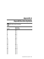
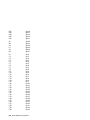
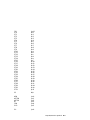
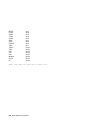
Appendix A Deposit/Examine Symbols
Examples
Example 2-1 Device Names .......................................................... <Write$84>
Example 3-1 Boot Command ........................................................ <Write$94>
Example 3-2 Build EEPROM Command ..................................... <Write$05>
Example 3-3 Cdp Command ......................................................... <Write$15>
Example 3-4 Clear EEPROM Command ..................................... <Write$25>
Example 3-5 Clear <envar> .......................................................... <Write$35>
Example 3-6 Clear Screen Command .......................................... <Write$45>
Example 3-7 Continue Command ................................................ <Write$55>
Example 3-8 Crash Command ...................................................... <Write$65>
Example 3-9 Create Command .................................................... <Write$75>
Example 3-10 Deposit Command ................................................. <Write$85>
Example 3-11 Examine Command ............................................... <Write$95>
Example 3-12 Help Command ...................................................... <Write$06>
Example 3-13 Initialize Command ............................................... <Write$16>
Example 3-14 Mchk command ..................................................... <Write$26>
Example 3-15 Repeat Command .................................................. <Write$36>
Example 3-16 Set Configuration Command ................................ <Write$46>
Example 3-17 Set EEPROM Command ....................................... <Write$56>
iv
Example 3-18
Example 3-19
Example 3-20
Example 3-21
Example 3-22
Example 3-23
Example 3-24
Example 3-25
Example 3-26
Example 3-27
Example 3-28
Example 3-29
Example 3-30
Example 3-31
Example 3-32
Set <envar> ....................................................................... 3-30
Set Host Command ............................................... <Write$66>
Set Power Command ............................................. <Write$76>
Show Configuration Command ............................ <Write$86>
Show Device Command ......................................... <Write$96>
Show EEPROM Command ................................... <Write$07>
Show <envar> ........................................................ <Write$17>
Show Memory Command ...................................... <Write$27>
Show Network Command ..................................... <Write$37>
Show Power Command ......................................... <Write$47>
Start Command ..................................................... <Write$57>
Stop Command ...................................................... <Write$67>
Test Command ...................................................... <Write$77>
Update Command ................................................. <Write$87>
Comment (#, !) Command ..................................... <Write$97>
Figures
Figure 1-1
Figure 1-2
Figure 1-3
System Hardware .................................................... <Write$08>
System Controls and Connections .......................... <Write$18>
Determining the Boot Processor ............................. <Write$28>
Tables
Table 1
Table 2
Table 2-1
Table 2-2
Table 2-3
Table 2-4
Table 3-1
Table 3-2
Table 3-3
Table 3-4
Table 3-5
Table 3-6
DEC 7000/VAX 7000 Documentation ........ <neon_doc_tab (1)>
Related Documents ................................. <related_doc_tab (1)>
Console Command Language Syntax .................... <Write$38>
Console Special Characters ..................................... <Write$48>
Environment Variables .......................................................... 2-7
Device Name Fields ................................................. <Write$58>
Cdp Command Options ............................................ <Write$68>
Deposit Command Options ...................................... <Write$78>
Device Name and Address Space Options .............. <Write$88>
Examine Command Options .................................... <Write$98>
Device Name and Address Space Options .............. <Write$09>
Test Command Options ........................................... <Write$19>
v
vi
Preface
Intended Audience
This manual is written for the system manager or system operator.
Document Structure
This manual uses a structured documentation design. Topics are organized into small sections for efficient on-line and printed reference. Each
topic begins with an abstract. You can quickly gain a comprehensive overview by reading only the abstracts. Next is an illustration or example,
which also provides quick reference. Last in the structure are descriptive
text and syntax definitions.
This manual has three chapters and one appendix, as follows:
•
Chapter 1, Console Hardware, briefly describes the console hardware.
•
Chapter 2, Console User Interface, describes command syntax,
special characters, environment variables, and device naming conventions.
•
Chapter 3, Console Commands, describes each command and gives
examples.
•
Appendix A, Deposit/Examine Symbols, lists the symbols recognized by the deposit and examine commands.
vii
Conventions Used in This Document
Commands and command options are printed in bold type; for example,
The help command displays ....
Although commands and environment variables are not case sensitive
(that is, Boot and BOOt are both valid), commands and command options
are shown in lowercase type.
When a command may be abbreviated, the portion that may be omitted is
shown in brackets: -flags or -fl[ags]. Brackets also indicate an element is
optional.
Braces ({}) indicate a choice from the enclosed list.
Angle brackets (<>) indicate that the enclosed text is not a literal depiction
of the element but instead a reference to the kind of item that can appear
in that position.
Terminology. Unless specified otherwise, the use of "system" refers to
either a DEC 7000 AXP or VAX 7000 system. The DEC 7000 AXP systems
use the Alpha AXP architecture. References in text use DEC 7000 to refer
to DEC 7000 AXP systems.
When a discussion applies to only one system, an icon is used to highlight
that system. Otherwise, the discussion applies to both systems. Thus, the
abstract for a module that applies only to DEC 7000 systems would look
like this:
This section shows a sample boot of OpenVMS Alpha AXP
DEC from the RRD42 CD drive for DEC 7000 systems. The first
7000
step is issuing the show device command to determine the
location of the RRD42.
Book titles. In text, if a book is cited without a product name, that book is
part of the hardware documentation. It is listed in Table 1 along with its
order number.
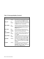
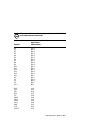
Documentation Titles
Table 1 lists the books in the DEC 7000 and VAX 7000 documentation set.
Table 2 lists other documents that you may find useful.
viii
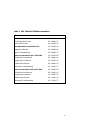
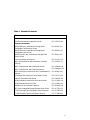
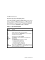
Table 1 DEC 7000/VAX 7000 Documentation
Title
Order Number
Installation Kit
EK–7000B–DK
Site Preparation Guide
EK–7000B–SP
Installation Guide
EK–700EB–IN
Hardware User Information Kit
EK–7001B–DK
Operations Manual
EK–7000B–OP
Basic Troubleshooting
EK–7000B–TS
Service Information Kit—VAX 7000
EK–7002A–DK
Platform Service Manual
EK–7000A–SV
System Service Manual
EK–7002A–SV
Pocket Service Guide
EK–7000A–PG
Advanced Troubleshooting
EK–7001A–TS
Service Information Kit—DEC 7000
EK–7002B–DK
Platform Service Manual
EK–7000A–SV
System Service Manual
EK–7002B–SV
Pocket Service Guide
EK–7700A–PG
Advanced Troubleshooting
EK–7701A–TS
ix
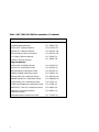
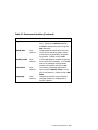
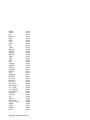
Table 1 DEC 7000/VAX 7000 Documentation (Continued)
Title
Order Number
Reference Manuals
Console Reference Manual
EK–70C0B–TM
KA7AA CPU Technical Manual
EK–KA7AA–TM
KN7AA CPU Technical Manual
EK–KN7AA–TM
MS7AA Memory Technical Manual
EK–MS7AA–TM
I/O System Technical Manual
EK–70I0A–TM
Platform Technical Manual
EK–7000A–TM
Upgrade Manuals
x
KA7AA CPU Installation Guide
EK–KA7AA–IN
KN7AA CPU Installation Guide
EK–KN7AA–IN
MS7AA Memory Installation Guide
EK–MS7AA–IN
KZMSA Adapter Installation Guide
EK–KXMSX–IN
DWLMA XMI PIU Installation Guide
EK–DWLMA–IN
DWMBB VAXBI PIU Installation Guide
EK–DWMBB–IN
H7237 Battery PIU Installation Guide
EK–H7237–IN
H7263 Power Regulator Installation Guide
EK–H7263–IN
BA654 DSSI Disk PIU Installation Guide
EK–BA654–IN
BA655 SCSI Disk and Tape PIU
Installation Guide
EK–BA655–IN
Removable Media Installation Guide
EK–TFRRD–IN
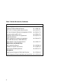
Table 2 Related Documents
Title
Order Number
General Site Preparation
Site Environmental Preparation Guide
EK–CSEPG–MA
System I/O Options
BA350 DECstor/me Modular Storage Shelf
Subsystem Configuration Guide
EK–BA350–CG
BA350 DECstor/me Modular Storage Shelf
Subsystem User’s Guide
EK–BA350–UG
BA350-LA DECstor/me Modular Storage Shelf
User’s Guide
EK–350LA–UG
CIXCD Interface User Guide
EK–CIXCD–UG
DEC FDDIcontroller 400 Installation/Problem
Solving
EK–DEMFA–IP
DEC LANcontroller 400 Installation Guide
EK–DEMNA–IN
DEC LANcontroller 400 Technical Manual
EK–DEMNA–TM
DSSI VAXcluster Installation and Troubleshooting
Manual
EK–410AA–MG
InfoServer 150 Installation and Owner’s Guide
EK–INFSV–OM
KDM70 Controller User Guide
EK–KDM70–UG
KFMSA Module Installation and User Manual
EK–KFMSA–IM
KFMSA Module Service Guide
EK–KFMSA–SV
RRD42 Disc Drive Owner’s Manual
EK–RRD42–OM
RF Series Integrated Storage Element User Guide
EK–RF72D–UG
TF85 Cartridge Tape Subsystem Owner’s Manual
EK–OTF85–OM
TLZ06 Cassette Tape Drive Owner’s Manual
EK–TLZ06–OM
xi
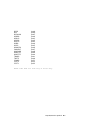
Table 2 Related Documents (Continued)
Title
Order Number
Operating System Manuals
Alpha Architecture Reference Manual
EY–L520E–DP
DEC OSF/1 Guide to System Administration
AA–PJU7A–TE
DECnet for OpenVMS Network Management Utilities
AA–PQYAA–TK
Guide to Installing DEC OSF/1
AA–PS2DA–TE
OpenVMS Alpha Version 1.0 Upgrade and
Installation Manual
AA–PQYSA–TE
VMS Upgrade and Installation Supplement:
VAX 7000–600 and VAX 10000–600 Series
AA–PRAHA–TE
VMS Network Control Program Manual
AA–LA50A–TE
VMSclusters and Networking
HSC Installation Manual
EK–HSCMN–IN
SC008 Star Coupler User’s Guide
EK–SC008–UG
VAX Volume Shadowing Manual
AA–PBTVA–TE
Peripherals
Installing and Using the VT420 Video Terminal
EK–VT420–UG
LA75 Companion Printer Installation and User Guide
EK–LA75X–UG
xii
Chapter 1
Console Hardware
This chapter describes how the console program and hardware function in
DEC 7000 and VAX 7000 systems. Sections include:
•
Processor Console Hardware
•
System Controls and Connections
•
Primary and Secondary Processors
Console Hardware 1-1
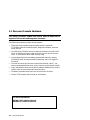
1.1 Processor Console Hardware
The system processor module has several features dedicated to
support of the console and diagnostic hardware.
The following hardware provides console support:
•
128-Kbyte flash-erasable programmable read-only memories
(FEPROMs) hold the console program, diagnostic software, and bootstrap routines.
•
One 128-Kbyte FEPROM contains code that performs minimal initialization and testing functions required to bring up the console environment. It also contains flash ROM recovery code.
•
One 8-Kbyte electrically erasable programmable read-only memory
(EEPROM) holds console parameters, bootstrap, and error logging information.
•
One dual universal asynchronous receiver/transmitter (UART) supports programmable baud rates, parity, stop bits, and character length.
•
Logic and registers allow the console to enable or disable halts, cause a
system reset, and provide console communication.
•
Hardware provides time-of-year and interval timer functions.
•
Several LEDs display status and error information.
For more information:
KN7AA CPU Technical Manual
KA7AA CPU Technical Manual
1-2 Console Hardware
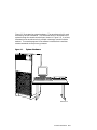
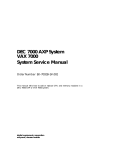
Figure 1-1 illustrates the system hardware. The console terminal is used
for entering console commands. The console terminal is connected to the
system through the console terminal port (shown in Figure 1-2). A printer,
connected to the console terminal, provides a hardcopy record of console
sessions. The console program is the software interface that translates
console commands to the primary processor.
Figure 1-1
System Hardware
LA75 Companion Printer
d i g i t a l
BXB-0023-92
Console Hardware 1-3
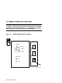
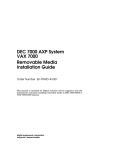
1.2 System Controls and Connections
The system control panel consists of a keyswitch and three indicator lights. Three cable ports provide connections for expander
cabinets and the console terminal. In a multiprocessor system,
each processor has access to the console terminal line.
Figure 1-2
System Controls and Connections
Disable
Front
Secure
Enable
Left Expander
Restart
Key On
Right Expander
Run
Fault
Console
BXB-0015A-92
1-4 Console Hardware
The control panel keyswitch (see Figure 1-2) has the following settings:
Disable
Removes 48 VDC power from the system. Power is still
supplied to the cabinet control logic (CCL) module.
Secure
Prevents entry into console mode; position used while
machine executes programs.
Enable
Allows entry into console mode; position used while
machine executes programs.
Restart
A momentary switch position, used to reinitialize the
system; causes self-test to start running.
The control panel indicator lights, when lit, indicate:
Key On
Power is supplied to entire system; the blower is running.
Run
Lit when the primary processor is running the operating
system or user programs; off when the primary processor
is in console mode.
Fault
Fault on LSB, XMI bus, or an I/O bus. Flashes during
power sequencing or when errors are detected.
The signals for the control panel Run light, the console terminal, and the
power system UARTs are carried by the system bus. A processor that is in
console mode can perform I/O directly to the console terminal.
For more information:
Operations Manual
Console Hardware 1-5
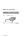
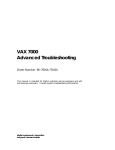
1.3 Primary and Secondary Processors
One processor is selected as the boot processor, and all other processors become secondary processors. This determination is made
by the system at power-up or initialization and can be altered using console commands.
Figure 1-3
Determining the Boot Processor
Secondary Processors
Boot
Processor
LSB Bus
BXB-0007A-92
1-6 Console Hardware
One processor in a multiprocessor system is designated as the primary
processor. Since the primary processor performs the system bootstrap, it is
also referred to as the boot processor. The lowest numbered enabled processor that has asserted its own boot processor bit is the boot processor. All
console commands execute, by default, on the primary processor.
Under the operating system, secondary processors must communicate with
the primary when they need to perform I/O on the console terminal using
the hardware restart parameter block (HWRPB).
The low portion of main memory is reserved for the console program.
When the system is booted, the console image is preserved in order to facilitate reentering the console program through a halt condition. In addition, a number of data structures are created in memory, primarily for
communication between the console program and the operating system.
For more information:
Operations Manual
Advanced Troubleshooting
KN7AA CPU Technical Manual
KA7AA CPU Technical Manual
Console Hardware 1-7
Chapter 2
Console User Interface
This chapter describes the console program’s command language, console
special characters, console environment variables, and device naming conventions. Console commands (see Chapter 3) allow you to boot the operating system, display the configuration, and verify the system.
When the system is in console mode, the system is halted and the console
firmware is executing. The operator communicates with the firmware
through the console terminal, which displays the following prompt:
>>>
P0n>>>
for a uniprocessor system, or
for a multiprocessor system
where n is 0 to 5, depending on which LSB slot the primary processor is in.
Sections in this chapter include:
•
Command Syntax
•
Console Special Characters
•
Console Environment Variables
•
Device Naming Conventions
Console User Interface 2-1
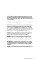
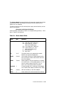
2.1 Command Syntax
The console command language has syntax rules for forming commands. Commands can contain up to 80 characters on a single
line, can be abbreviated, and accept options. Numbers are in
hexadecimal notation. Tabs and spaces are compressed.
Table 2-1
Console Command Language Syntax
Command Parameter
Attribute or Action
Length
80 characters maximum, unless the continuation character (\) is used.
Case
Upper- or lowercase characters are accepted.
Abbreviation
Varies with the command; usually the shortest unique combination of letters.
Options
Can appear after the command keyword or
after any symbol or number in the command. Begin with a hyphen (-) and must be
preceded by at least one space.
Numbers
Hexadecimal format unless otherwise noted.
No characters
Null command; no action taken.
Multiple adjacent spaces
and tabs
Compressed to a single space.
2-2 Console User Interface
Length: The console program accepts commands of up to 80 characters per
line. This does not include the terminating carriage return or any characters deleted as the command is entered. A command longer than 80 characters, without the backslash character (see Section 2.2) causes the display
of an error message.
Case: Upper- or lowercase characters can be used for input. Characters
are displayed in the case they are entered.
Abbreviation: Commands and options can be abbreviated by dropping
characters from the end of words. You must enter the minimum number of
characters to identify the keyword unambiguously. All characters specified must match a keyword to be accepted. For example, although E
uniquely identifies the examine command, Exmn is not a valid abbreviation. In the command reference sections that follow, characters that can be
omitted appear in square brackets ([ ]). Abbreviation of environment variables (see Section 2.3) is allowed with the show command.
Options: You can use command options, to define or modify the environment, after the command keyword or after any symbol or number in the
command. See individual keyword descriptions for examples.
Numbers: Numbers in console commands are in hexadecimal notation
unless otherwise indicated. The hexadecimal (0X) default can be overridden by preceding decimal numbers by 0D, binary by 0B, and octal by
0O. Refer to the individual command descriptions. Register names (R0,
R1, and so on) are not considered numbers and use decimal notation.
No Characters: A command line with no characters is a null command.
The console program takes no action and does not issue an error message.
The console prompt returns. The console supports command line recall
and editing.
Spaces: Multiple adjacent spaces and tabs are compressed and treated as
a single space. The console program ignores leading and trailing spaces.
Console User Interface 2-3
2.2 Console Special Characters
The console program supports control characters, entered by holding down the Control (Ctrl) key and pressing the desired key, and
other special characters.
Table 2-2
Console Special Characters
Character
Function
Return
Backslash
<X]
Help
Carriage return; ends a command line.
Line continuation.
Delete key; deletes previously typed character.
By itself, displays first-level help. When pressed
after part of a command, displays options available.
Ctrl/A, F14
Ctrl/B, ^ (up-arrow)
Ctrl/C
Ctrl/D, <
Ctrl/E
Ctrl/F, >
Toggles between insertion/overstrike mode.
Recall previous command(s).
Terminate running process.
Move cursor left one position.
Move cursor to end of line.
Move cursor right one position.
Ctrl/H, BS, F12
Ctrl/J
Ctrl/O
Ctrl/Q
Ctrl/R
Ctrl/S
Ctrl/U
Move cursor to beginning of line.
Delete word.
Stop output to console terminal for current
command. Toggles between enable/disable.
In console mode, acts like Ctrl/C. In program
mode, causes the boot processor to halt and begin
running the console program.
Resume output to console terminal.
Redisplay the current line.
Stop output to console terminal.
Delete entire line.
*
""
#, !
Wildcarding for certain commands.
Quotes for set environment variable name.
Comment specifiers.
Ctrl/P
2-4 Console User Interface
Return terminates command line input. No action is taken on a command
line until it is terminated by a carriage return. If no characters are entered and the Return key is pressed, it is treated as a null command. No
action is taken, and the console prompts for input. Carriage return is echoed as carriage return, line feed.
Backslash (\) allows continuation across lines from the terminal; must
be the last character on the line to be continued.
When the Delete key is pressed, the console deletes the character previously typed.
Help provides additional information on console commands.
Ctrl/A or F14 toggles between insertion mode and overstrike mode for
command line editing. The default mode is overstrike.
Ctrl/B or up-arrow/down-arrow recall the previous command(s). The
last 16 commands are stored in the recall buffer.
Ctrl/C terminates the current command. Echoed as ^C, Ctrl/C clears
Ctrl/S and also resumes output that was suspended using Ctrl/O. When
Ctrl/C is entered as part of a command line, the line is deleted as if you
entered Ctrl/U. Ctrl/C has no effect as part of a binary data stream.
Ctrl/D or left-arrow moves the cursor one position to the left.
Ctrl/E moves the cursor to the end of the line.
Ctrl/F or right-arrow moves the cursor right one position.
Ctrl/H, Backspace, or F12 moves the cursor to the beginning of the line.
Ctrl/J deletes previously typed word.
Ctrl/O stops output to the console terminal until Ctrl/O is entered again.
Ctrl/O is echoed as ^O followed by a carriage return and is not echoed
when output is reenabled. Output is also reenabled when the console
prompts for a command, issues an error message, enters program mode, or
when Ctrl/P is entered. It is not reenabled by displaying a repeat command.
Ctrl/P works like Ctrl/C and is echoed as ^C, if the console terminal is in
console mode. If the console terminal is in program mode and is secured,
Ctrl/P is not echoed, but is passed to the operating system for processing.
If the console terminal is in program mode and is not secured, Ctrl/P halts
the processor and begins the console program. See the continue command for additional information.
Ctrl/Q resumes console output to the console terminal that was suspended
with Ctrl/S. Additional Ctrl/Q strokes are ignored. Ctrl/Q is not echoed.
Console User Interface 2-5
Ctrl/R is echoed as ^R, followed by a carriage return, line feed, and printing the current command line. Deleted characters are omitted. This command is useful for hardcopy terminals.
Ctrl/S suspends output to the console terminal until Ctrl/Q is entered.
Ctrl/S is not echoed.
Ctrl/U discards all characters that you entered on the current line. It is
echoed as ^U, followed by a carriage return, line feed, and a new prompt.
* allows wildcarding with device names and environment variables.
Wildcarding is allowed with the following commands:
1.
cdp
2.
clear
3.
initialize
4.
set -d
5.
show
6.
show configuration
7.
show device
8.
show <envar>
9.
show network
10. stop
11. test
12. update
See Chapter 3 for specific examples.
Double quotes (" ") allow you to denote a string for environment variable
assignment.
# and ! allow you to enter a comment. All characters following a # or ! are
recognized as a comment only. Exceptions include the above control characters.
2-6 Console User Interface
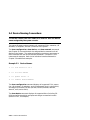
2.3 Console Environment Variables
Console environment variables allow the user to modify the way
the console commands operate.
An environment variable is a name and value association maintained by
the console program. The value associated with an environment variable
is an ASCII string (up to 127 characters in length) or an integer. Certain
environment variables are typically modified by the user to tailor the recovery behavior of the system on power-up and after system failures. Volatile environment variables are initialized by a system reset; others are
nonvolatile across system failures.
Environment variables can be created, modified, displayed, and deleted using the create, set, show, and clear commands. A default value is associated with any variable that is stored in EEPROM. This default value is
used if the EEPROM is unreadable.
Table 2-3 lists the predefined console environment variables, their attributes, and their functions. Refer to Chapter 3, Console Commands, for examples of their use.
Table 2-3
Environment Variables
Variable
Attribute
Function
auto_action
Nonvolatile
Specifies the action the console will take following an error halt. Values are:
restart - Automatically restart. If restart
fails, boot the operating system.
boot - Automatically boot the operating
system.
halt (default) - Enter console mode.
baud
Nonvolatile
Sets the console terminal port baud rate.
Allowable values are 300, 600, 1200, 2400,
4800, and 9600. The default value is 9600.
Console User Interface 2-7
Table 2-3 Environment Variables (Continued)
Variable
Attribute
Function
bootdef_dev
Nonvolatile
The default device or device list from
which booting is attempted when no device
name is specified by the boot command.
boot_file
Nonvolatile
The default file name used for the primary
bootstrap when no file name is specified by
the boot command, if appropriate.
boot_osflags
Nonvolatile
Additional parameters to be passed to the
system software during booting if none are
specified by the boot command with the
-flags qualifier.
boot_reset
Nonvolatile
Resets system and displays self-test results during booting. Default value is on.
cpu
Volatile
Selects the current boot processor.
cpu_enabled
Nonvolatile
A bitmask indicating which processors are
enabled to run (leave console mode). Default is 0xff.
cpu_primary
Nonvolatile
A bitmask indicating which processors are
enabled to become the next boot processor,
following the next reset. Default is 0xff.
d_harderr
Volatile
Determines action taken following a hard
error. Values are halt (default) and continue. Applies only when using the test
command.
d_report
Volatile
Determines level of information provided
by the diagnostic reports. Values are
summary (default) and full. Applies only
when using the test command.
2-8 Console User Interface
Table 2-3 Environment Variables [Continued)
Variable
Attribute
Function
d_softerr
Volatile
Determines action taken following a soft
error. Values are continue (default)
and halt. Applies only when using the
test command.
dump_dev
Nonvolatile
Complete device specification of the device to which operating system dumps
are written (if supported by the operating system). Default value is null.
enable_audit
Nonvolatile
If set to on (default), enables the generation of audit trail messages. If set to off,
audit trail messages are suppressed.
Console initialization sets this to on.
interleave
Nonvolatile
The memory interleave specification.
Value must be default, none, or an explicit interleave list. Default value is default.
language
Nonvolatile
Determines whether system displays
message numbers or message text in
English (default).
Console User Interface 2-9
2.4 Device Naming Conventions
To use the console, the user needs to be familiar with the device
names assigned by the system console.
The system firmware assigns names to all supported CPUs, memories, I/O
windows, I/O adapters, and end I/O devices in the system.
The show configuration, show device, and show network commands
(see Chapter 3) are used to obtain the assigned device mnemonics for all
devices in the system. The assigned mnemonics provide an easy means to
refer to devices with the various console commands. Example 2-1 illustrates several examples. Refer to the individual console commands in
Chapter 3 for additional examples.
Example 2-1
Device Names
1. >>> test dua23.0.1.14.1
2. >>> set host demna0
3. >>> update kn7aa* -f
4. >>> examine xmi0:21880004
The show configuration command displays all supported CPUs, memories, I/O windows, I/O adapters, and I/O subsystems (that is, whole XMIs)
and assigns a mnemonic to each (ka7aa0, ms7aa3, dwlma0, demna0,
demna1, xmi0, and so forth).
The show device command displays all supported disks (including CDROM and solid state disks) and tapes and assigns a mnemonic to each
(dua23.0.1.14.1, for example).
2-10 Console User Interface
The show network command displays all supported network boot devices
(Ethernet and FDDI) and assigns a mnemonic to each (exa0.0.0.14.0,
fxb0.0.0.4.1, for example).
The device name for end I/O devices (disks, tapes, network devices, and so
forth) is of the form:
ddccuuuu.node.channel.slot.hose
where the fields, described in Table 2-4, are separated by periods (.). Numbers in Table 2-4 are decimal.
Table 2-4
Device Name Fields
Field
Size
Definition
dd
2
Protocol used to access device:
DK - SCSI disk (DEC 7000 only)
DU - MSCP disk (CI, SI, and
DSSI [VAX 7000 only])
MK - SCSI tape (DEC 7000 only)
MU - MSCP tape (CI, SI, and
DSSI [VAX 7000 only])
EX - XMI Ethernet
FX - XMI FDDI
cc
1 or 2
Controller letter (a–zz) assigned by console,
based on the system configuration.
uuuu
4 (max)
Unit number of device (0–9999) determined by
the I/O channel number and the XMI slot number of the adapter.
node
3 (max)
Node number (0–255) of the device on a remote
(CI or DSSI) bus. If the remote node is a CI, this
is the CI node number of the HSC; if it is a
DSSI, this is the node number of the disk.
channel
1
Channel number (0–1); used only if the adapter
is a KFMSA (VAX 7000) or KZMSA (DEC 7000).
slot
2 (max)
XMI slot number (1–14) of the adapter.
hose
1
Hose number (0–3) that connects to the I/O bus.
Console User Interface 2-11
Chapter 3
Console Commands
Console commands provide the capabilities to examine and modify system
state. Additionally, they allow tests to be directed to functional components of the system. The following console commands are described:
•
boot
•
build eeprom
•
cdp - VAX 7000 only
•
clear (eeprom, <envar>, screen)
•
continue
•
crash
•
create
•
deposit
•
examine
•
help
•
initialize
•
mchk - DEC 7000 only
•
repeat
•
set (configuration, eeprom, <envar>, host, power)
•
show (configuration, device, eeprom, <envar>, memory, network,
power)
•
start
•
stop
•
test
•
update
•
comment (#, !)
Console Commands 3-1
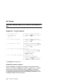
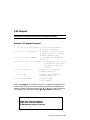
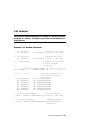
3.1 Boot
The boot command boots the operating system.
Example 3-1
Boot Command
1. >>>
# Boot from local disk.
>>> show device
# Display I/O device information.
polling for units on kfmsa0, slot 1, xmi0...
dua2.2.0.1.0
R2TDYC$DIA2 RF73
polling for units on kdm700, slot 2, xmi1...
dua1.0.0.2.1
DUA1
RA92
>>> boot dua2.2.0.1.0#
#
#
#
#
#
#
#
Boot device designations:
du = device code.
a = controller designation.
2 = device unit number.
2 = node number.
0 = device channel number.
1 = XMI slot number.
0 = I/O channel number.
2. >>>
# Boot from network device.
>>> show net
# Display network information.
polling for units on demna0, slot 3, xmi0...
exa0.0.0.3.0 08-00-2B-0B-BB-ED
# exa0.0.0.3.0 = path info.
# 08-00-2B-0B-BB-ED = controller
# hardware address (hex).
>>> b exa0 -flags 0,0,0 -file ISL_LVAX_V02
# Boot from InfoServer.
# exa0 = network device.
# -flags 0,0,0 = additional
# command parameters.
# ISL_LVAX_V02 = load file.
(Examples are continued on p. 3-4)
3-2
Console Commands
The boot command syntax is:
b[oot] [-flags NNNN, M, PPPP] [-file <filename>] <device_name>
where the -flags parameter allows additional boot command parameters
N, M, and P. Specifying -fl[ags] overrides the boot_osflags environment
variable (see Section 2.3). The NNNN flags, dependent on the system configuration, are used with OpenVMS VAX when booting from a shadow set.
The M flag, dependent on the system configuration, specifies the system
root of the boot device. The PPPP flags are for the operating system bootstrap loader options. The -file parameter indicates booting from the file
<filename>. Specifying -file overrides the boot_file environment variable (see Section 2.3). Device names can be found by using the show device and show network commands. See Section 2.4 for information on
device names.
Boot command flags can be shortened, since values such as zero or commas (which can be used as placeholders) do not have to be specified. These
parameters are read from right to left (PPPP, M, NNNN). For example,
boot -fl 0,0,100 or boot -fl ,,100 are the same as boot -fl 100, where 100
is the value of the P option.
For more information:
Operations Manual
VMS Upgrade and Installation Supplement:
VAX 7000-600 and VAX 10000-600 Series
Console Commands 3-3
3. >>>
>>> sh dev
# Boot a system in a CI
# VAXcluster.
# Display I/O device information.
polling for units on cixcd0, slot 2, xmi0...
dua20.14.0.2.2
$100$DUA20
RA82
dua31.14.0.2.2
$100$DUA31
RA82
>>> boot -fl 0,4,0 dua20.14.0.2.2
# -fl[ags] indicates additional
# command options follow.
# 0 = not a shadow set boot
# 4 = system root of boot device.
# 0 = bootstrap loader options.
# du = device code.
# a = controller designation.
# 20 = device unit number.
# 14 = node number.
# 0 = device channel number.
# 2 = XMI slot number.
# 2 = I/O channel number.
4. >>>
# Shadow set boot.
>>> b -fl 8DAC,2,0 dua3500.14.0.12.1,dua63.14.0.12.1
# 8DAC = load device virtual
# unit number;
# 8 indicates shadow set booting.
# DAC = value (hex) of virtual
# device unit number 3500 (dec.).
# 2 = system root.
# 0 = bootstrap loader options.
# dua3500 = virtual device.
# dua63 = physical device.
# 14 = node number.
# 0 = device channel number.
# 12 = XMI slot number.
# 1 = I/O channel number.
# The console attempts to boot
# from the virtual device; then
# from the physical device. The
# parameters for the physical and
# virtual device are identical
# except for device number.
3-4
Console Commands
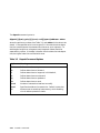
3.2 Build EEPROM
The build eeprom command is used to create a new EEPROM image or to restore a corrupted EEPROM image.
Example 3-2
Build EEPROM Command
>>> build eeprom
# Build EEPROM if invalid
# message is displayed.
Creating new EEPROM image
System Serial Number> GAO1234567
Module Serial Number> SG226LFH01
#
#
#
#
#
#
Module Unified 2-5-2-4 Part Number>
Module Firmware Revision> 1.5
>>>
If the EEPROM is
corrupted, enter
system serial number
and module serial
number, part number,
and firmware revision.
-E2040-AA. M06
The build eeprom command syntax is:
bu[ild] ee[prom]
If you are restoring a corrupted EEPROM, you will be prompted to supply
the system serial number and module serial, part, and firmware revision
numbers. The build eeprom command may be required during a console
firmware upgrade. Before upgrading, you should refer to Table 2-3 and
use the show <envar> command (see Section 3.24) to display present environment variables values. After rebuilding, use the set <envar> command (see Section 3.18) to set the environment variables to their desired
values.
For more information:
Advanced Troubleshooting
Release Notes
Console Commands 3-5
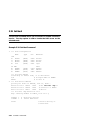
3.3 Cdp
The cdp command performs basic configuration manageVAX
7000 ment of DSSI devices.
Example 3-3
Cdp Command
1. >>> show device
# Display I/O device
# information.
polling for units on kfmsa0, slot 0, xmi0...
dua5.0.0.13.0
BASHFL$DIA5
RF71
polling for units on cixcd0, slot 14, xmi1...
dub44.1.0.13.1
$1$DIA44 (BLANK4) RF71
>>> cdp -i
dua.5.0.0.13.0:
# -i entered to select
# interactive mode - set all
# parameters; no changes made.
Node Name [BASHFL]?
Allocation Class [0]?
Unit Number [5]?
dub44.1.0.13.0:
Node Name [BLANK4]?
Allocation Class [1]?
Unit Number [44]?
2. >>> cdp -n dua5
dua5.0.0.13.0:
Node Name [BASHFL]?
#
#
#
#
3. >>> cdp -a
#
dua5.0.0.13.0:
#
Allocation Class [0]? #
dub44.1.0.13.0:
#
Allocation Class [1]?
3-6
Console Commands
-n dua5 entered to set device
node name of dua5; no change
made.
Press Return to exit.
-a entered to set device
allocation class, allclass,
for all DSSI devices; no
changes made.
The cdp command syntax is:
cdp [-{a,i,n,o,u}] [-sn] [-sa <val>] [dssi_device]
where <val> is allclass or unitnum, and dssi_device is the DSSI device.
Table 3-1 summarizes the cdp command options. The cdp command permits the modification of DSSI device parameters from the console without
explicit connection to a node’s DUP server. The parameters modified are
the DUP task parameters nodename, allclass, and unitnum.
Table 3-1
Cdp Command Options
Option
Function
-a
Sets device allocation class, allclass.
-i
Selects interactive mode; sets all parameters.
-n
Sets device node name, nodename (up to 16 characters).
-o
Overrides warning messages.
-u
Sets device unit number, unitnum.
-sa
allclass
Sets allclass for all DSSI devices in the system to the
specified value.
-sn
Sets nodename to either RFhscn or TFhscn
h is the device hose number (0–3)
s is the device slot number (1–14)
c is the device channel number (0, 1)
n is the device node ID number (0–6)
-su
unitnum
Sets the starting unitnum for the first DSSI device in the
system to the specified value. Subsequent DSSI unit numbers are incremented from this base.
Console Commands 3-7
3.4 Clear EEPROM
The clear eeprom command allows you to clear the selected
EEPROM option.
Example 3-4
Clear EEPROM Command
>>> clear eeprom log
# Clears all failure
# information logged in
# EEPROM.
The clear eeprom command syntax is:
cl[ear] ee[prom] <option>
The clear eeprom command can be used to clear diag_sdd, diag_tdd,
symptom, or log.
For more information:
Advanced Troubleshooting
3-8
Console Commands
3.5 Clear <envar>
Clear <envar> is used to remove an environment variable.
Example 3-5
Clear <envar>
>>> create fred
fred set to
# Create fred with null value
>>> set fred "this is a string in an environment variable"
fred set to this is a string in an environment variable
>>> show fred
fred
this is a string in an environment variable
>>> clear fred
>>> show fred
Environment variable not found
>>>
The clear <envar> removes an environment variable. However, some environment variables, such as baud, are permanent and cannot be removed.
The clear command syntax is:
cl[ear] <envar>
where <envar> is the name of an environment variable, for example, a
boot specification to be cleared (see Table 2-3).
Console Commands 3-9
3.6 Clear Screen
The clear screen command allows you to clear the terminal screen.
Example 3-6
Clear Screen Command
>>> clear screen
# Refresh the terminal
# screen.
The clear screen command syntax is:
cl[ear] sc[reen]
There are no parameters or options.
3-10
Console Commands
3.7 Continue
The continue command resumes processing at the point where it
was interrupted by a Ctrl/P. Programs continue executing at the
address currently in the program counter of the processor.
Example 3-7
Continue Command
$ ^P
# VAX 7000 example
# Stop processing on boot processor;
# processor enters console mode.
Console entry reason: ^P or Node Halt
Entry PC: 80805442
Entry PSL: 041F8200
# System responds with message; system
# has halted with 80805442 in the
# program counter (PC).
>>>
#
#
#
#
#
#
#
#
.
.
.
>>> continue
Console session begins
Processor resumes at the address
where processing was stopped by
Ctrl/P. Here processing continues
at address 80805442.
Console Commands 3-11
The continue command syntax is:
c[ontinue]
Continue causes the primary processor to resume program mode, executing at the address currently in the program counter (PC). This address is
the address that was in the PC when the primary processor received a
Ctrl/P command. The system displays the hexadecimal PC value.
When the boot processor receives a continue command, it does not perform processor initialization as it would for a boot procedure. The boot
processor just returns to the program it was processing.
Following execution of the continue command, the console terminal enters program mode, and any ASCII characters entered on the console terminal are passed on to the operating system. In program mode, the console terminal acts like any other terminal on the system until a Ctrl/P is
issued to return it to console mode.
NOTE: ^P followed by continue should be used selectively since some console commands (for example, cdp, deposit, set host, show device,
show network, and test) can corrupt the machine state so that the
execution of the current program cannot resume successfully.
3-12
Console Commands
3.8 Crash
The crash command causes the operating system to be restarted
and generates a memory dump.
Example 3-8
Crash Command
P01>>> crash
[operating system output appears]
The crash command causes the operating system to be restarted in such a
way as to force a crash. This allows the user to ^P a hung system and generate a memory dump.
The crash command syntax is:
cra[sh]
There are no parameters or options. See the mchk command.
Console Commands 3-13
3.9 Create
The create command allows you to create an environment variable.
Example 3-9
Create Command
1. >>> create fred
fred set to
>>> show fred
fred
# Create a new environment
# variable fred with a value
# equal to null.
2. >>> create stuff 356
# Create a new environment
# variable stuff with a value
# equal to 356.
3. >>> create -nv delay
#
#
#
#
Create a new nonvolatile
environment variable delay
in EEPROM with a value
equal to null.
4. >>> create -nv work "dua44.0.0.4.0"
# Create a new nonvolatile
# environment variable work
# in EEPROM equal to
# dua44.0.0.4.0.
5. >>> cr bootspec "-flags 0,1
#
#
#
dua21.0.0.14.1"
Create an environment
variable bootspec equal to
-flags 0,1 dua21.0.0.14.1.
The create command syntax is:
cr[eate] [-nv] <envar> [<value>]
where the -nv option indicates the nonvolatile environment variable is
stored in EEPROM, and <value> is the optional variable value. Created
environment variables are volatile by default. value can be a quoted
string for specifying boot specifications (see boot command description).
For additional information on environment variables, see Section 2.3 and
the clear and set command descriptions.
3-14
Console Commands
3.10 Deposit
The deposit command stores data in a specified location.
Example 3-10 Deposit Command
1. >>> dep -b -n 1FF pmem:0 0 # Clear first 512 bytes
# of physical memory.
2. >>> d -l -n 3 vmem:1234 5
# Deposit 5 into four long# words starting at virtual
# memory address 1234.
3. >>> d -n 8 R0 FFFFFFFF
# Load GPRs R0 through R8
# with -1.
4. >>> d -1 -n 10 -s 200 pmem:0 8 #
#
#
#
5. >>> d -1 pmem:0 0
>>> d + FF
6. >>> d scbb 800000
Deposit 8 in the first
longword of the first
17 pages in physical
memory.
# Deposit 0 to physical
# memory address 0.
# Deposit FF to physical
# memory address 4.
# Deposit SCBB
# with 800000.
When using deposit, if no options are given in subsequent commands, the
system uses the options from the preceding commands as the defaults for
address or location referenced, data type (-b, -l, -w, and so forth), data size
for increment (-s), and address space (gpr, ipr, pmem, and so forth).
For more information:
KN7AA CPU Technical Manual
KA7AA CPU Technical Manual
MS7AA Memory Technical Manual
Console Commands 3-15
The deposit command syntax is:
d[eposit] [-{b,w,l,q,o,h,u}] [-{n val, s val}] [space:]<address> <data>
where the options are values from Table 3-2, and <data> is the value to be
stored. If the specified value is too large to fit in the data size to be deposited, the console ignores the command and issues an error response. For
data lengths longer than a longword, each longword of data should be
separated by a space. If the data is smaller than the data size to be deposited, the higher order bits are filled with zeros.
Table 3-2
Deposit Command Options
Option
Meaning
-b
Defines data size as a byte.
-h
Defines data size as a hexword.
-l
Defines data size as a longword; initial default,
-o
Defines data size as an octaword.
-q
Defines data size as a quadword.
-w
Defines data size as a word.
-n val
Number of consecutive locations to modify.
-s val
Specifies the address increment size. Default is data size.
-u
Allows access to console private memory, while disabling
virtual address protection checks.
3-16
Console Commands
space: is the optional device name (or address space) of the device to access (see Table 3-3), and address specifies the offset within a device to
which data is deposited. Valid symbolic address forms (see Appendix A)
include:
•
fpr-name, a symbol representing a floating-point register (DEC 7000
only).
•
gpr-name, a symbol representing a general purpose register.
•
ipr-name, a symbol representing the internal processor register.
•
PC, the program counter. The address space is set to GPR.
•
PSL, the processor status longword (VAX 7000 only).
•
pt-name, a symbol representing a PAL temp register (DEC 7000 only).
•
+, the location immediately following the last location referenced in an
examine or deposit command. For physical and virtual memory, the
referenced location is the last location plus the size of the reference (1
for byte, 2 for word, 4 for longword). For other address spaces, the address is the last referenced address plus one.
•
−, the location immediately preceding the last location referenced in an
examine or deposit command. For physical and virtual memory, the
referenced location is the last location minus the size of the reference
(1 for byte, 2 for word, 4 for longword). For other address spaces, the
address is the last referenced address minus one.
•
*, the last location referenced in an examine or deposit command.
•
@, the location addressed by the last location referenced in an examine or deposit command.
NOTE: Since the console program actually resides in low memory when
running, depositing to memory should be done with care.
Console Commands 3-17
Table 3-3
Device Name and Address Space Options
Option
Device Name and Address Space Meaning
<dev_ name>
Device name: xmi0, ka7aa1, demna0, and so forth.
fpr
Defines the address space as the floating-point register set, F0 through F31 (DEC 7000 only).
gpr
Defines the address space as the general register set,
R0 through R15.
ipr
Defines the address space as the internal processor
registers (IPRs).
pt
Defines the address space as the PAL temp register
set, PT0 through PT31 (DEC 7000 only).
pmem
Defines the address space as physical memory; initial
default.
vmem
Defines the address space as virtual memory. All access and protection checking occur.
For more information:
Alpha Architecture Reference Manual
3-18
Console Commands
3.11 Examine
The examine command displays the contents of a memory location,
a register, or a device. The options are similar to the deposit command options.
Example 3-11 Examine Command
1. >>> examine pc
gpr: 000000F (
PC) 00000000
# Examine the program
# counter - VAX 7000.
2. >>> examine sp
gpr: 000000E (
SP) 00012FB8
# Examine the stack
# pointer - VAX 7000.
3. >>> examine psl
# Examine the processor
# status longword # VAX 7000.
CM TP FPD IS CURMOD PRVMOD IPL DV FU IV T N Z V C
PSL 041F0000 0 0 0 1 KERNEL KERNEL 1F 0 0 0 0 0 0 0 0
4. >>> e
gpr:
gpr:
gpr:
gpr:
gpr:
gpr:
gpr:
-n 6 r4
00000004
00000005
00000006
00000007
00000008
00000009
0000000A
(
(
(
(
(
(
(
R4)
R5)
R6)
R7)
R8)
R9)
R10)
# Examine register R4 and
# the next 6 registers # DEC 7000.
00000003F4000000
0000000000001404
FFFFFFFF80680000
0000000000000000
0000010000000000
0000000000000002
0000000000000001
5. >>> examine pmem:400EC
# Examine physical
pmem: 000400EC A762FAF847E11411 # memory - DEC 7000.
6. >>> examine demna0:0
# Examine demna0’s
demna0: 00000000 0000000108020C03 # Device Register # DEC 7000.
Console Commands 3-19
The examine command syntax is:
e[xamine] [-{b,w,l,q,o,h,d,u}] [-{n val, s val}] [space:] <address>
where the options are values from Table 3-4, space: is the optional device
name (or address space) of the device to access, and address is a longword
that specifies the first location to be examined. Appendix A lists the symbols recognized by the examine (and deposit) command.
The display line consists of the device name, the hexadecimal address or
offset within the device, and the examined data also in hexadecimal.
Table 3-4
Examine Command Options
Option
Meaning
-b
Defines data size as a byte.
-d
Disassembles instruction at current address.
-h
Defines data size as a hexword.
-l
Defines data size as a longword; initial default.
-o
Defines data size as an octaword.
-q
Defines data size as a quadword.
-w
Defines data size as a word.
-n val
Number of consecutive locations to examine.
-s val
Specifies the address increment size. Default is data
size.
-u
Allows access to private console memory, while disabling
virtual address protection checks.
For more information:
KN7AA CPU Technical Manual
KA7AA CPU Technical Manual
MS7AA Memory Technical Manual
3-20
Console Commands
Examine uses most of the same options as deposit. Additionally, the examine command supports the -d option (instruction decode, which will
disassemble the instructions at the current address). When using examine, if no options are given in subsequent commands, the system uses the
options from the preceding commands as the defaults for address or location referenced, data type, including -d, (-b, -l, -w, and so forth), data size
for increment (-s), and address space (gpr, ipr, pmem, and so forth).
After initialization, the default address space is physical memory, the default data size is a longword, the default address is zero, and the default
address increment size is the data size. If conflicting address space or data
sizes are specified, the console ignores the command and issues an error
response.
Table 3-5
Device Name and Address Space Options
Option
Device Name and Address Space Meaning
<dev_name>
Device name: xmi0, ka7aa1, demna0, and so forth.
fpr
Defines the address space as the floating-point register
set, F0 through F31 (DEC 7000 only).
gpr
Defines the address space as the general register set,
R0 through R15. The data size is always a longword.
ipr
Defines the address space as the internal processor
registers (IPRs). The data size is always a longword.
pt
Defines the address space as the PAL temp register
set, PT0 through PT31 (DEC 7000 only).
pmem
Defines the address space as physical memory.
vmem
Defines the address space as virtual memory. All access and protection checking occur.
Console Commands 3-21
3.12 Help
The help command provides basic information on the console commands, when the system is in console mode.
Example 3-12 Help Command
1. >>> help create
# Display basic create command
# information. Minimum
# command input is highlighted.
create [-nv] <envar> <value>
2. >>> h examine
examine[-{b,w,l,q,o,h,d,u}][-n val][-s val][space:]address
-{b,w,l,q,o,h}
! data length
-d
! decode instruction
-n <count>
! repeat count
-s <size>
! repeat address increment size
-u
! protected mode
3. >>> help
boot
build
clear
# Display help information on
# all console commands beginning
# with boot.
[-flags <val>] [-filename <name>] <device_list>
<option>
<option> or <envar>...
The help command syntax is:
h[elp] [<option>]
where <option> is one of the console commands. The <helpkey> can
also be used after a partial command has been typed. For example,
set <helpkey> will display the options supported by the set command.
3-22
Console Commands
3.13 Initialize
The initialize command performs a reset. You can initialize the
entire system or a specified device or subsystem.
Example 3-13 Initialize Command
>>> initialize demna0
The initialize command syntax is:
i[nitialize] [<device_name>]
where <device_name> is the name of the device or subsystem to be initialized. If <device_name> specifies a memory module, you will receive a
message stating that memory cannot be initialized, since the console runs
from main memory. See Section 2.4 for information on how to learn device
names in the system.
The initialize command can be used to reset the entire system or a specified device, except memory nodes. Initialize only applies to modules and
not end I/O devices (that is, init kdm70* would be a valid command, but
init dua* would not be valid). If no option is specified, a full system reset
is performed.
The initialize command (with no device specified) and turning the
keyswitch on the system control panel to Restart perform the same function: both reset the machine and run systemwide self-test.
Self-test results are displayed after a system reset but not after a device
reset.
For more information:
Basic Troubleshooting
Console Commands 3-23
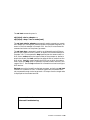
3.14 Mchk
The mchk command is used to dump internal state inforDEC
7000 mation to aid in the diagnosis of hardware failures.
Example 3-14 Mchk command
>> mchk
V5.25-1/01.14-1
pal_flags
8450010860000005
PTBR ipr: 0000000A ( PTBR) 0000000000000000
SCBB ipr: 0000000B ( SCBB) 0000000000000000
PCBB ipr: 00000008 ( PCBB) 0000000000001000
exc_addr
pmem: 00006130 0000000000031930
iccsr
pmem: 00006148 00000000009F0000
hirr
pmem: 00006160 0000000000000042
mm_csr
pmem: 00006168 00000000000053A0
dc_stat
pmem: 00006170 0000000000000007
dc_addr
pmem: 00006178 00000007FFFFFFFF
biu_stat
pmem: 00006188 0000000000000250
biu_addr
pmem: 00006190 0000000000006120
biu_ctl
pmem: 00006198 0000000850006447
fill_syndrome pmem: 000061A0 0000000000000000
fill_addr
pmem: 000061A8 0000000000006140
va
pmem: 000061B0 0000000000006190
lep_gbus
pmem: 000061C0 0020000000000038
lber
pmem: 000061CC 00000021
lmerr
pmem: 000061D4 00000000
lbesr0
pmem: 000061D8 0000000C
lbesr1
pmem: 000061DC 0000000C
lbesr2
pmem: 000061E0 0000000C
lbesr3
pmem: 000061E4 0000000C
lbecr0
pmem: 000061E8 0000DE98
lbecr1
pmem: 000061EC 00004040
vhit
pmem: F8000F80 00000000
tag
pmem: 00006008 00E0055500000010
dwlma XBE
xmi0: 60000004 0000000100000142
dwlma LERR xmi0: 6000004C 0000000100068000
>>>
3-24
Console Commands
The mchk command is typically used after a system crash to provide internal state information to aid in diagnosing hardware failures. The
mchk command syntax is:
mchk [n]
where [n] is the LSB node id of the processor you are interested in. By
default, you will get information from the primary processor.
Console Commands 3-25
3.15 Repeat
The repeat command reexecutes the command that you pass as its
argument until Ctrl/C is entered.
Example 3-15 Repeat Command
>>> repeat
P 00000000
P 00000000
P 00000000
^C
>>>
examine 00000000
EEEDFACC
EEEDFACC
EEEDFACC
# Perform the specified
# command until stopped
# by Ctrl/C.
The repeat command syntax is:
r[epeat] [<command>]
where <command> is the console command to repeat. To stop the repeat
command, enter Ctrl/C.
3-26
Console Commands
3.16 Set Configuration
The set configuration command records the current system configuration in EEPROM.
Example 3-16 Set Configuration Command
>>> set configuration
The set configuration command syntax is:
se[t] c[onfiguration]
The command takes no options. This command is used with the show
configuration -s command.
Console Commands 3-27
3.17 Set EEPROM
The set eeprom command allows you to set the selected EEPROM
option.
Example 3-17 Set EEPROM Command
1. >>> set eeprom field
LARS #> 09494820
Message> EEPROM update
>>>
2. >>> set eeprom man
#
#
#
#
#
Enter labor activity
reporting system (LARS)
number (8 digits) and
message (up to 68
characters).
# Enter module serial number,
# part number, and firmware
# revision.
Module Serial Number> SG226LFH01
Module Unified 2-5-2-4 Part Number>
Module Firmware Revision> 1.5
>>>
3-28
Console Commands
-E2040-AA. M06
The set eeprom command syntax is:
se[t] ee[prom] <option>
where option is field, manufacturing, or serial.
For more information:
Advanced Troubleshooting
Console Commands 3-29
3.18 Set <envar>
Set <envar> allows you to modify environment variables.
Example 3-18 Set <envar>
1. >>> set auto_action restart #
#
#
#
#
On an error halt, system
will automatically restart. If restart fails,
boot the operating
system.
2. P00>>> set cpu 1
cpu set to 1
P01>>>
# Designate CPU in slot
# 1 as the primary, or
# boot, processor.
3. >>> set d_harderr halt
# System will halt on hard
# error.
4. >>> se class
# Set the value of
# environment variable
# class to null.
5. >>> show enable*
enable_audit
OFF
>>> set enable_audit on
#
#
#
#
#
#
Display the status
of the enable_audit
environment variable. Set
enable_audit on to enable
generation of audit trail
messages.
The set <envar> syntax is:
se[t] <envar> [value]
where envar (environment variable) and value are from Table 2-3, which
also indicates which environment variables are volatile. Certain environment variables, such as boot specifications, must be defined using the create command. For additional information, see Section 3.9. Unambiguous
abbreviations can be used for an environment variable name when using
the set command. Set -d envar resets the value of envar to its default
value. Wildcarding is also allowed with the set command. For example,
set -d * resets all environment variables to their default values.
3-30
Console Commands
Example 3-18 Set <envar> (Continued)
6. >>> set interleave 5,7:6
# Creates a 4-way
# interleave set.
In the above example, assume there are three memory arrays, as follows:
Node 5 - 128 Mbytes
Node 6 - 64 Mbytes
Node 7 - 64 Mbytes
By default, the console creates a 4-way interleave by combining nodes 6
and 7 and interleaving the resulting 128 Mbytes with the other 128 Mbyte
array. (The 4-way interleaving results from the on-board 2-way interleaving of the 128 Mbyte arrays.) Three operators are used with the set interleave command: comma (,) plus (+), and colon (:). , separates interleave
sets, + separates members of a given interleave set, and : groups smaller
arrays together to form larger members of a set. Set interleave 5+6:7
produces a memory interleave identical to set interleave default. Set
interleave 5,6,7 produces a memory interleave identical to set interleave none.
For more information:
MS7AA Memory Technical Manual
Console Commands 3-31
3.19 Set Host
The set host command allows you to connect to another console or
service. The -dup option is used to invoke the DUP server on the
selected node.
Example 3-19 Set Host Command
1. >>> show configuration
Name
Type
Rev
Mnemonic
KA7AA
MS7AA
MS7AA
IOP
(8002)
(4000)
(4000)
(2000)
0000
0000
0000
0001
ka7aa0
ms7aa0
ms7aa1
iop0
C0 XMI
8+ DWLMA
C+ KDM70
E+ DEMNA
(102A)
(0C22)
(0C03)
0104
1E11
0802
xmi0
dwlma0
kdm700
demna0
LSB
0+
1+
7+
8+
>>> set host demna0
Connecting to remote node, ^Y to disconnect.
T/R
# To begin RBDs on DEMNA
RBDE>
# in Slot E.
2. >>> show device kdm700
polling for units on kdm700, slot 12, xmi0...
dua32.0.0.12.0 DUA32
RA70
# Use set host -dup to
dua34.0.0.12.0 DUA34
RA70
# connect to a KDM70
dua77.0.0.12.0 DUA77
RA70
# device.
>>> set host -dup dua32.0.0.12.0
dup: starting DIRECT on kdm70_a.0.0.12.0 ()
DIRECT
ILEXER
1
1
D
D
Directory Utility
InLine Exerciser
Task?
3-32
Console Commands
# Select utility or
# exerciser.
The set host command syntax is:
se[t] h[ost] <device_adapter> or
se[t] h[ost] <-dup> <-bus b> node [task]
The set host <device_adapter> command is used to connect to a remote
XMI adapter for running XMI module-resident ROM-based diagnostics, as
shown in the first example in Example 3-19. Use Ctrl/Y to terminate the
command and return to the primary processor.
The set host -dup... command is used to run diagnostics and utilities on
devices that support the DUP protocol, as shown in the second example in
Example 3-19. In the command, -dup specifies that the remote node is a
DUP server, node specifies the node number of the processor or device to
attach the console, and task specifies the optional task to invoke from the
DUP driver. -bus b is used to specify the DSSI bus on which the node resides. When the -dup option is specified, the node number must be in the
range of 0 to 7. See the cdp command for information on how to configure
DSSI devices.
Set host can only be issued from the boot processor, and only one set host
command is in effect at a time. Characters typed from the console terminal are passed through to the target node. All output from the target node
is displayed on the console terminal.
For more information:
Advanced Troubleshooting
Console Commands 3-33
3.20 Set Power
The set power command is used to configure the system power
regulators for battery backup.
Example 3-20 Set Power Command
>>> set power -b 8 left
>>>
The set power command syntax is:
se[t] p[ower] -b <value> <option>
where -b allows you to configure the system with batteries, <value> is the
number of batteries (4 or 8), and <option> is the cabinet containing the
batteries (main, left, or right).
3-34
Console Commands
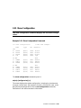
3.21 Show Configuration
The show configuration command displays the last saved configuration.
Example 3-21 Show Configuration Command
>>> show configuration
# DEC 7000 example
Name
Type
Rev
Mnemonic
KN7AA
MS7AA
MS7AA
IOP
(8001)
(4000)
(4000)
(2000)
000B
0000
0000
0006
kn7aa0
ms7aa0
ms7aa1
iop0
C0 XMI
1+ DEMNA
4+ KDM70
8+ DWLMA
(0C03)
(0C22)
(102A)
0802
1E11
0104
xmi0
demna0
kdm700
dwlma0
C1 XMI
6+ DEMNA
8+ DWLMA
D+ KDM70
E+ KZMSA
(0C03)
(102A)
(0C22)
(0C36)
0802
0104
1E11
413F
xmi1
demna1
dwlma1
kdm701
kzmsa0
LSB
0+
6+
7+
8+
The show configuration command syntax is:
sh[ow] c[onfiguration] [-s]
The screen displays the system configuration, including the hardware device type, revision level, and mnemonic for each LSB and XMI node. -s displays the saved configuration (from the set configuration command).
See Section 2.4 for device mnemonic information.
Console Commands 3-35
3.22 Show Device
Displays device information for any disk/tape adapter or group of
adapters.
Example 3-22 Show Device Command
>>> show device kdm700
polling for units on kdm700, slot 12, xmi0
dua32.0.0.12.0 DUA32
RA70
dua34.0.0.12.0 DUA34
RA70
dua77.0.0.12.0 DUA77
RA70
The show device command syntax is:
sh[ow] dev[ice] [<dev_name>]
See Section 2.4 for information on how to learn device names in the system. Show device with no <dev_name> gives all devices in the system.
<dev_name> can be any CIXCD, KDM70, or KFMSA (VAX 7000 only)
adapter name (wild-carding is allowed). For example, show device
cixcd* will display information on all CIXCD devices in the system.
3-36
Console Commands
3.23 Show EEPROM
The show EEPROM command allows you to display selected
EEPROM information.
Example 3-23 Show EEPROM Command
1. >>> show eeprom serial
# Display system serial
# number.
System Serial Number = GAO1234567
2. >>> show eeprom manufacturing # Display manufacturing
# information.
Module Serial Number = SG226LFH01
Module Part Number =
-E2040-AA. M06
Module Firmware Revision = 1.5
The show eeprom command syntax is:
sh[ow] ee[prom] <option>
where option is diag_sdd, diag_tdd, symptom, field, manufacturing, or serial.
Console Commands 3-37
3.24 Show <envar>
Show <envar> displays the current state of the specified environment variable.
Example 3-24 Show <envar>
1. >>> show auto_action
auto_action
restart
>>>
2. >>> show baud
baud
9600
3. >>> show d_harderr
d_harderr
halt
4. >>> show enable*
enable_audit
OFF
# Displays status of
# enable_audit
5. >>> show interleave
interleave
none
The show envar command syntax is:
sh[ow] <envar> or sh[ow] *
where envar is an environment variable name (see Table 2-3). Unambiguous abbreviations can be used for an environment variable name when using the show <envar> command. See the set <envar> command for related information.
3-38
Console Commands
3.25 Show Memory
The show memory command displays memory module information.
Example 3-25 Show Memory Command
>>> show memory
Set
--A
Node
---7
Size
---128M
Base Addr
--------000000000
Intlv
----2-Way
Position
-------0
The show memory command syntax is:
sh[ow] m[emory]
In the above example, the memory module at node 7 is in a two-way system interleave indicated by the first interleave set A. The total memory
size is 128 Mbytes. See the set interleave example in Section 3.18 for additional information.
For more information:
Basic Troubleshooting
MS7AA Memory Technical Manual
Console Commands 3-39
3.26 Show Network
The show network command displays the names and physical addresses of all known network devices in the system.
Example 3-26 Show Network Command
>>> show network
polling for units on demna0, slot 14, xmi0...
exa0.0.0.14.0: 08-00-2B-24-3F-E1
polling for units on demfa0, slot 14, xmi1...
exb0.0.0.14.2: 08-00-2B-0B-BB-FF
The show network command syntax is:
sh[ow] ne[twork]
There are no options or qualifiers.
3-40
Console Commands
3.27 Show Power
The show power command gives the power status of the system.
Example 3-27 Show Power Command
>>> show power
Cabinet: Main
Regulator :
A
B
C
------------------------------------------------------------------------------Primary Micro Firmware Rev :
2.0
2.0
2.0
Secondary Micro Firmware Rev :
2.0
2.0
2.0
Power Supply State :
NORMAL
NORMAL
BBU MODE
AC Line Voltage (V RMS) :
113.71
114.35
115.93
DC Bulk Voltage (VDC) :
227.02
227.02
227.02
48V DC Bus Voltage (VDC) :
47.57
47.57
47.57
48V DC Bus Current (ADC) :
30.17
29.68
29.58
48V Battery Pack Voltage (VDC) :
50.85
50.72
47.91
24V Battery Pack Voltage (VDC) :
25.56
25.56
23.95
Battery Pack Charge Current (IDC) :
2.91
2.90
0
Ambient Temperature (Degree C) :
26.22
24.80
24.75
Elapsed Time (Hours) :
290.00
290.00
290.00
Remaining Battery Capacity (Minutes) :
8.00
8.00
8.00
Battery Cutoff Counter (Cycles) :
0
1.00
1.00
Battery Configuration : 4 Batteries 4 Batteries 4 Batteries
Heatsink Status :
NORMAL
NORMAL
NORMAL
Battery Pack Status :
CHARGING
CHARGING
DISCHG’G
Last UPS Test Status :
PASSED
PASSED
TESTING
LDC POWER Status
: 0
PIU Primary Status
: 0
PIU Secondary Status : 0
Console Commands 3-41
The show power command syntax is:
sh[ow] p[ower] [-{h,s}] [option]
where -s displays the current status (default) and -h the history status
(value of each parameter at the last system shutdown) and option selects
the cabinet (main, right, or left).
3-42
Console Commands
3.28 Start
The start command begins execution of an instruction at the address specified in the command string. The start command does
not initialize the system.
Example 3-28 Start Command
>>> start 40000000
# Start processor at
# address 40000000.
The start command syntax is:
s[tart] address
where address is the address the PC is set to start execution. The start
command is equivalent to continue, except you can specify the address at
which to begin executing.
NOTE: The start command should be used selectively since some console
commands (for example, cdp, deposit, set host, show device,
show network, and test) may corrupt the machine state so that
execution of the current program may not resume successfully.
Console Commands 3-43
3.29 Stop
The stop command halts a specified processor.
Example 3-29 Stop Command
P00>>> stop ka7aa1
# Stop the secondary processor.
The stop command syntax is:
sto[p] <cpu_device_name>
where <cpu_device_name> specifies the secondary processor to be
halted. The stop command does not control the running of diagnostics and
does not apply to adapters or memories.
3-44
Console Commands
3.30 Test
The test command allows you to test the entire system, a portion of
the system (subsystem), or a specific device. By default, the entire
system is tested.
Example 3-30 Test Command
1. >>> test -t 300
# Test the entire system.
# -t 300 specifies a system test
# run time of 300 seconds.
2. >>> t -nowrite "dua*" -write -t 60
# Test disk write/read/compare.
# This example is a system test
# since no dev_arg is given.
# Write/read/compare testing of
# disks is specified for all
# disks not associated with
# controller "a". Test run time
# is 60 seconds.
3. >>> t xmi0
# Test all devices associated
# with XMI0.
4. >>> test kdm701
# Test kdm701 and all associated
# devices.
For more information:
Basic Troubleshooting
Advanced Troubleshooting
Console Commands 3-45
The test command syntax is:
t[est][-write][-nowrite "list"][-omit "list"][-t time][-q][dev_arg]
where dev_arg specifies the target device, group of devices, or subsystem
to test. A list of available devices and subsystem mnemonics in the system can be obtained by issuing a show configuration, show device, or
show network command. You would then issue the test dev_arg command to test the desired device. Table 3-6 lists the command options.
If no parameter is specified, the entire system is tested. Note that system
testing performed by the test command is very different from that performed during power-on or reset. To execute systemwide self-test, use the
initialize command.
Table 3-6
Test Command Options
Option
Meaning
-write
Selects writes to media as well as reads (read only is the
default). Only applicable to disk testing (ignored otherwise).
-nowrite
"list"
Used with -write to prevent selected devices or groups of
devices from being written to.
-omit
"list"
Specifies device not to test; takes a single device or device
list as a qualifier.
-t time
Run time in seconds for the test command, following system sizing and configuration; default for system test is
600 seconds (10 minutes).
-q
Quiet option prevents testing start and stop informational
messages from being displayed on the console terminal.
Error messages are always reported.
3-46
Console Commands
3.31 Update
The update command copies the contents of the boot processor’s
EEPROM or FEPROM to the EEPROM or FEPROM of the specified
secondary processor(s).
Example 3-31 Update Command
1. P00>>> update -ee ka7aa1
# CPU 0 is the primary CPU.
# Copy EEPROM to CPU 1.
Update ka7aa1’s EEPROM [Y/N]? Y
Updating ka7aa1’s EEPROM done
P00>>> set cpu 1
# Makes CPU 1 the primary.
P01>>> update -fl ka7aa0 # Copy FEPROM to CPU 0.
Update ka7aa0’s FLASH ROMS [Y/N]? Y
Updating ka7aa0’s FLASH ROMs ....done
2. P00>>> update ka7aa* -fl
# Use wildcarding to update
# all CPUs.
Update ka7aa1’s FLASH ROMS [Y/N]? Y
Updating ka7aa1’s FLASH ROMs ....done
Update ka7aa2’s FLASH ROMS [Y/N]? Y
Updating ka7aa2’s FLASH ROMs ....done
Console Commands 3-47
The update command syntax is:
up[date] -f[lash] -e[eprom] <device_name>
where <device_name> is the CPU mnemonic of the secondary processor
(displayed with the show configuration command) that is to receive the
contents of the primary processor’s FEPROM or EEPROM. By default,
neither EEPROM/FEPROMs are updated.
The update -eeprom command copies the parameters that can be set as
well as any additional information stored in the EEPROM of the boot processor. Note that update copies from the primary CPU to the specified target CPU. If you wish to update the primary CPU with data from a secondary CPU, you must first use set cpu. In the first example above, we have
a dual-processor system and want to propagate the EEPROM from CPU 0
to CPU 1, but the FEPROM from CPU 1 into CPU 0. This might occur in a
multiprocessor upgrade where the new CPU (CPU 1) has newer FEPROM
code, but CPU 0 contains site-specific boot parameters, and so forth.
Update should be issued following any field service installation of a new
CPU. Updated information includes systemwide console parameters, baud
rate, interleave, terminal characteristics, and saved boot specifications.
3-48
Console Commands
3.32 Comment (#, !)
A comment can be introduced using the # symbol or ! symbol. The
entire comment is ignored.
Example 3-32
Comment (#, !) Command
1. >>> # This example illustrates the comment command.
>>>
2. >>> exam pmem:0400EC ! Examine physical memory.
pmem: 000400EC D0FFFFFD
>>>
Console Commands 3-49
Appendix A
Deposit/Examine Symbols
DEC
7000
This section lists symbols recognized by the DEC 7000 deposit and examine commands.
Symbol
Equivalent
Space:Offset
R0
R1
R2
R3
R4
R5
R6
R7
R8
R9
R10
R11
R12
R13
R14
R15
R16
R17
R18
R19
R20
R21
R22
R23
R24
R25
R26
gpr:0
gpr:1
gpr:2
gpr:3
gpr:4
gpr:5
gpr:6
gpr:7
gpr:8
gpr:9
gpr:a
gpr:b
gpr:c
gpr:d
gpr:e
gpr:f
gpr:10
gpr:11
gpr:12
gpr:13
gpr:14
gpr:15
gpr:16
gpr:17
gpr:18
gpr:19
gpr:1a
Deposit/Examine Symbols A-1
R27
R28
R29
R30
R31
gpr:1b
gpr:1c
gpr:1d
gpr:1e
gpr:1f
AI
RA
PV
FP
SP
RZ
gpr:19
gpr:1a
gpr:1b
gpr:1d
gpr:1e
gpr:1f
F0
F1
F2
F3
F4
F5
F6
F7
F8
F9
F10
F11
F12
F13
F14
F15
F16
F17
F18
F19
F20
F21
F22
F23
F24
F25
F26
F27
F28
F29
F30
fpr:0
fpr:1
fpr:2
fpr:3
fpr:4
fpr:5
fpr:6
fpr:7
fpr:8
fpr:9
fpr:a
fpr:b
fpr:c
fpr:d
fpr:e
fpr:f
fpr:10
fpr:11
fpr:12
fpr:13
fpr:14
fpr:15
fpr:16
fpr:17
fpr:18
fpr:19
fpr:1a
fpr:1b
fpr:1c
fpr:1d
fpr:1e
A-2 Deposit/Examine Symbols
F31
PT0
PT1
PT2
PT3
PT4
PT5
PT6
PT7
PT8
PT9
PT10
PT11
PT12
PT13
PT14
PT15
PT16
PT17
PT18
PT19
PT20
PT21
PT22
PT23
PT24
PT25
PT26
PT27
PT28
PT29
PT30
PT31
fpr:1f
pt:0
pt:1
pt:2
pt:3
pt:4
pt:5
pt:6
pt:7
pt:8
pt:9
pt:a
pt:b
pt:c
pt:d
pt:e
pt:f
pt:10
pt:11
pt:12
pt:13
pt:14
pt:15
pt:16
pt:17
pt:18
pt:19
pt:1a
pt:1b
pt:1c
pt:1d
pt:1e
pt:1f
PC
N/A
ASN
ASTEN
ASTSR
AT
FEN
IPIR
ipr:0
ipr:1
ipr:2
ipr:3
ipr:4
ipr:5
IPL
ipr:6
Deposit/Examine Symbols A-3
MCES
PCBB
PRBR
PTBR
SCBB
SIRR
SISR
TBCHK
TBIA
TBIAP
TBIS
ESP
SSP
USP
WHAMI
VPTB
PS
ipr:7
ipr:8
ipr:9
ipr:a
ipr:b
ipr:c
ipr:d
ipr:e
ipr:f
ipr:10
ipr:11
ipr:13
ipr:14
ipr:15
ipr:16
ipr:17
ipr:18
NOTE: some IPRs are read only or write only.
A-4 Deposit/Examine Symbols
VAX
7000
This section lists symbols recognized by the VAX 7000 deposit and examine commands.
Symbol
Equivalent
Space:Offset
R0
R1
R2
R3
R4
R5
R6
R7
R8
R9
R10
R11
R12
R13
R14
R15
AP
FP
SP
PC
PSL
gpr:0
gpr:1
gpr:2
gpr:3
gpr:4
gpr:5
gpr:6
gpr:7
gpr:8
gpr:9
gpr:a
gpr:b
gpr:c
gpr:d
gpr:e
gpr:f
gpr:c
gpr:d
gpr:e
gpr:f
N/A
KSP
ESP
SSP
USP
ISP
P0BR
P0LR
P1BR
P1LR
SBR
SLR
CPUID
ipr:0
ipr:1
ipr:2
ipr:3
ipr:4
ipr:8
ipr:9
ipr:a
ipr:b
ipr:c
ipr:d
ipr:e
Deposit/Examine Symbols A-5
PCBB
SCBB
IPL
ASTLVL
SIRR
SISR
ICCS
NICR
ICR
TODR
MCESR
SAVPC
SAVPSL
MAPEN
TBIA
TBIS
PME
SID
TBCHK
LMBOX
INTSYS
PMFCNT
PCSCR
ECR
MTBTAG
MTBPTE
BIU_CTL
DIAG_CTL
BC_TAG
BIU_STAT
BIU_ADDR
FILL_SYN
FILL_ADDR
STC_RESULT
BCDECC
CHALT
SIO
SOE_IE
QW_PACK
CLR_IO_PACK
VMAR
VTAG
VDATA
ICSR
ipr:10
ipr:11
ipr:12
ipr:13
ipr:14
ipr:15
ipr:18
ipr:19
ipr:1a
ipr:1b
ipr:26
ipr:2a
ipr:2b
ipr:38
ipr:39
ipr:3a
ipr:3d
ipr:3e
ipr:3f
ipr:79
ipr:7a
ipr:7b
ipr:7c
ipr:7d
ipr:7e
ipr:7f
ipr:a0
ipr:a1
ipr:a2
ipr:a4
ipr:a6
ipr:a8
ipr:aa
ipr:ac
ipr:ae
ipr:b0
ipr:b2
ipr:b4
ipr:b8
ipr:b9
ipr:d0
ipr:d1
ipr:d2
ipr:d3
A-6 Deposit/Examine Symbols
BPCR
BPC
BPCUNW
MP0BR
MP0LR
MP1BR
MP1LR
MSBR
MSLR
MMAPEN
PAMODE
MMEADR
MMEPTE
MMESTS
TBADR
TBSTS
PCADR
PCSTS
PCCTL
ipr:d4
ipr:d6
ipr:d7
ipr:e0
ipr:e1
ipr:e2
ipr:e3
ipr:e4
ipr:e5
ipr:e6
ipr:e7
ipr:e8
ipr:e9
ipr:ea
ipr:ec
ipr:ed
ipr:f2
ipr:f4
ipr:f8
NOTE: some IPRs are read only or write only.
Deposit/Examine Symbols A-7
Index
B
Examine command, 3-19
Boot processor, 1-6, 3-12
Build EEPROM command, 3-5
F
C
Cabinet control logic (CCL), 1-5
Cdp command, 3-6
Channel number, 2-11
Clear EEPROM command, 3-8
Clear screen command, 3-10
Clear <envar> command, 3-9
Command language syntax, 2-2
Comment (#, !) command, 3-49
Console prompt, 2-1
Console special characters, 2-4
Continue command, 3-11
Controller designation, 2-11
Control panel, 1-4
Crash command, 3-13
Create command, 3-14
Ctrl/C, 3-26
Ctrl/P, 3-11
D
Delete key, 2-5
Deposit command, 3-15
Device naming conventions, 2-10
Device search list, 3-4
DSSI device configuration, 3-6
DUP server, 3-32
E
EEPROM, 1-2, 2-7, 3-48
Enable, 1-5
Environment variable, 2-7, 3-10
Fault light, 1-5
FEPROM, 1-2, 3-48
Flash ROMs, 3-47
Floating-point register set, 3-18,
3-21
G
General register set, 3-18, 3-21,
A-1, A-5
H
Hardware restart parameter block
(HWRPB), 1-7
Help key, 3-22
Help command, 3-22
Hose number, 2-11
I
Indicator lights, 1-5
Initialize command, 3-23
Insert mode, 2-5
Instruction decode, 3-21
Internal processor registers, 3-18,
3-21, A-3, A-5
K
Keyswitch, 1-5
Key on light, 1-5
M
Mchk command, 3-24
Index-1
N
Node number, 2-11
Nonvolatile environment variable,
3-14
Null command, 2-3
O
Overstrike mode, 2-5
P
PAL temp register set, 3-18, 3-21
Primary processor, 3-48
Processor status register, 3-18,
3-21
Program counter, 3-11, 3-12
Show power command, 3-41
Show <envar> command, 3-38
Special characters, 2-4
Stop command, 3-44
System controls, 1-4
T
Test command, 3-45
U
UART, 1-2
Unit number, 2-11
Update command, 3-47
W
Wildcarding, 2-4, 3-30
R
Recall buffer, 2-5
Repeat command, 3-26
Restart, 1-5
Run light, 1-5
S
Secondary processor, 1-6, 3-44,
3-48
Secure, 1-5
Self-test, and initialize command,
3-23
Set configuration, 3-27
Set EEPROM command, 3-28
Set host command, 3-32
Set interleave, 3-31
Set power command, 3-34
Set <envar> command, 3-30
Show configuration command, 3-35
Show configuration command, 2-10
Show device command, 3-36
Show device command, 2-10
Show EEPROM command, 3-37
Show memory command, 3-39
Show network command, 2-11, 3-40
Index-2