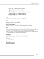
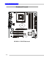
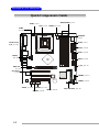
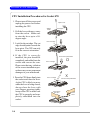
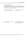
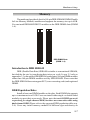
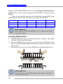
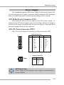
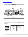
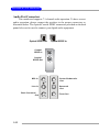
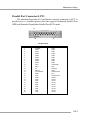
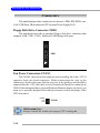
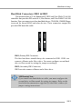
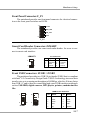
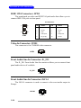
1
Getting Started
Chapter 1. Getting
Started
Getting Started
Thank you for purchasing the MD-8088 v1.X M-ATX
mainboard. The MD-8088 is based on Intel® 865PE & Intel®
ICH5 chipsets for optimal system efficiency. Designed to fit the
advanced Intel® Pentium 4 processor in the 478-pin package,
MD-8088 delivers a high performance and professional desktop
platform solution.
Information in this document is subject to
change without notice.
Medion® shall not be liable for errors contained herein or for
incidental or consequential damages in connection with the
furnishing, performance, or use of this material.
1-1
MD-8088 M-ATX Mainboard
Mainboard Specifications
CPU
h Supports Socket 478 for Intel® Pentium 4 (Socket 478) Northwood processor
h Supports up to 3.2 GHz P4 processor
Chipsets
h Intel® Springdale-865PE chipset
- Supports AGP 8x/4x at 0.8V (AGP 3.0) or 4x at 1.5V (not supports 3.3V)
- Supports 133/166/200MHz memory FSB
- Supports 400/533/800MHz Intel NetBurst micro-architecture bus.
h Intel® ICH5 chipset (421 mBGA)
- AC’97 2.3 interface
- 8 USB 2.0/1.1 ports
- 2 channel Ultra ATA/100 Bus Master IDE controller
- SMBus 2.0 support
Main Memory
h Supports eight memory banks using four 184-pin unbuffered DIMM
h Supports dual-channel function
h Max memory size is 4GB without ECC
h Supports DDR266/DDR333/DDR400 memory module
Slots
h Three 32-bit Master PCI Bus slot
h One mini PCI slot
h One AGP(Accelerated Graphic Port) slot
On-Board IDE
h An IDE controller on the ICH5 chipset provides IDE HDD/CD-ROM with
PIO, Bus Master and Ultra DMA66/100/133 operation modes.
h Can connect up to four IDE devices.
On-Board Peripherals
h On-Board Peripherals include:
- 1 floppy port supports 2 FDD with 360K, 720K, 1.2M, 1.44M and 2.88
Mbytes.
- 1 serial port
- 1 parallel port supports SPP/EPP/ECP mode
1-2
Getting Started
- 8 USB 2.0 / 1.1 ports (Rear*4 / Front*4)
- 1 Front USB 1.1 port for Card Reader
- 1 RJ45 connector
- 1 Rear 1394 port (6 Pins) / 1 Front 1394 port (4/6 Pins)
- 1 Optical SPDIF-In / 1 Optical SPDIF-Out
- 1 Coaxial SPDIF-In / 1 Coaxial SPDIF-Out
- 4 Line-Out / 1 Line-In
Audio
h S/W C-Media 9780 7.1 channel with SPDIF in/out.
LAN
h VIA® VT6105L LAN Controller
IEEE 1394 (Optional)
h VIA® VT6306 / VT6307 PCI 1394a Integrated Host Controller
BIOS
h The mainboard BIOS provides “Plug & Play” BIOS which detects the peripheral devices and expansion cards of the board automatically.
h The mainboard provides a Desktop Management Interface (DMI) function
which records your mainboard specifications.
Dimension
h M-ATX Form Factor: 24.38 cm (L) x 24.38 cm (W)
Mounting
h 6 mounting holes
Others
h Support STR/STD
h PC 2001 compliant
1-3
MD-8088 M-ATX Mainboard
Mainboard Layout
CFAN 1
JPW1
Winbond
83627TH F
JSMART1
ATX
Power Supply
FDD1
Top: S PDIF-In
Bottom : SP DIF-Out
IDE 1
IDE 2
Intel
865PE
JSCA1
JFW1
T: CS-Out
M:FS-Out
B:Line-Out
D IMM 3
D IMM 4
DIMM1
D IMM 2
AGP Slot
VIA
VT6306
F_P1
PCI Slot 1
VIA
VT6105L
PCI Slot 2
PCI Slot 3
Codec
JL_IN1
JVID1
JAUD 1
JBAT1
BATT
+
MD-8088 v1.X M-ATX Mainboard
1-4
MINIPCI1
JUSB1
JU SB2
ICH 5
BIOS
Hardware Setup
Chapter 2. Hardware
Setup
Hardware Setup
This chapter tells you how to install the CPU, memory
modules, and expansion cards, as well as how to setup the
jumpers on the mainboard. Also, it provides the instructions
on connecting the peripheral devices, such as the mouse,
keyboard, etc.
While doing the installation, be careful in holding the
components and follow the installation procedures.
2-1
MD-8088 M-ATX Mainboard
Quick Components Guide
DDR DIMMs, p.2-7
JPW1, p.2-9
CPU, p.2-3
CFAN1, p.2-14
JFW1,
p.2-18
JSMART1,
p.2-17
ATX1, p.2-9
Back Panel
I/O, p.2-10
FDD1, p.2-14
IDE2, p.2-15
JSCA1,
p.2-18
IDE1, p.2-15
F_P1, p.2-17
AGP slot,
p.2-19
PCI slots,
p.2-19
BIOS
BATT
+
JVID1, p.2-18
JAUD1, p.2-16
JL_IN1, p.2-18
2-2
JBAT1, p.2-19
JUSB2, p.2-17
JUSB1, p.2-17
Mini PCI Slot, p.2-19
Hardware Setup
Central Processing Unit: CPU
The mainboard supports Intel® Pentium® 4 Northwood processor in the
478 pin package. The mainboard uses a CPU socket called PGA478 for easy
CPU installation. When you are installing the CPU, make sure the CPU has a
heat sink and a cooling fan attached on the top to prevent overheating. If you
do not find the heat sink and cooling fan, contact your dealer to purchase and
install them before turning on the computer.
2-3
MD-8088 M-ATX Mainboard
CPU Installation Procedures for Socket 478
1. Please turn off the power and
Open Lever
unplug the power cord before
installing the CPU.
2. Pull the lever sideways away
Sliding
Plate
90 degree
from the socket. Make sure
to raise the lever up to a 90degree angle.
3. Look for the cut edge. The cut
edge should point towards the
lever pivot. The CPU can only
fit in the correct orientation.
4. If the CPU is correctly
installed, the pins should be
completely embedded into the
socket and can not be seen.
Please note that any violation
of the correct installation procedures may cause permanent
damages to your mainboard.
5. Press the CPU down firmly into
the socket and close the lever.
As the CPU is likely to move
while the lever is being closed,
always close the lever with
your fingers pressing tightly
on top of the CPU to make sure
the CPU is properly and completely embedded into the
socket.
2-4
Dot / Cut edge
Correct CPU placement
Dot / Cut edge
Dot / Cut edge
O
X
Incorrect CPU placement
Press down
the CPU
Close
Lever
Hardware Setup
Installing the CPU Fan
As processor technology pushes to faster speeds and higher performance,
thermal management becomes increasingly important. To dissipate heat, you
need to attach the CPU cooling fan and heatsink on top of the CPU. Follow the
instructions below to install the Heatsink/Fan:
1. Locate the CPU and its retention
mechanism on the motherboard.
2. Position the heatsink onto the retention mechanism.
3. Mount the fan on top of the heatsink.
Press down the fan.
4. Press the two levers down to fasten
the fan. Each lever can be pressed
down in only ONE direction.
2-5
MD-8088 M-ATX Mainboard
5. Connect the fan power cable from the mounted fan to the 3-pin fan power connector on the board.
NOTES
2-6
Hardware Setup
Memory
The mainboard provides 4 slots for 184-pin DDR SDRAM DIMM (Double
In-Line Memory Module) modules and supports the memory size up to 4GB.
You can install DDR400/DDR333 modules on the DDR DIMM slots (DIMM
1~4).
DDR DIMM Slots
(DIMM 1~4)
Introduction to DDR SDRAM
DDR (Double Data Rate) SDRAM is similar to conventional SDRAM,
but doubles the rate by transferring data twice per cycle. It uses 2.5 volts as
opposed to 3.3 volts used in SDR SDRAM, and requires 184-pin DIMM modules
rather than 168-pin DIMM modules used by SDR SDRAM. Please note that
the DDR SDRAM does not support ECC (error correcting code) and registered
DIMM.
DDR Population Rules
Install at least one DIMM module on the slots. Each DIMM slot supports
up to a maximum size of 1GB. Users can install either single- or double-sided
modules to meet their own needs. Please note that each DIMM can work
respectively for single-channel DDR, but there are some rules while using
dual-channel DDR (Please refer to the suggested DDR population table on p.
2-8). Users may install memory modules of different type and density on
2-7
MD-8088 M-ATX Mainboard
different-channel DDR DIMMs. However, the same type and density memory
modules are necessary while using dual-channel DDR, or instability may
happen.
Please refer to the following table for detailed dual-channel DDR. Other
combination not listed below will function as single-channel DDR.
DIMM1 (Ch A)
128MB~1GB
128MB~1GB
DIMM2 (Ch A)
128MB~1GB
128MB~1GB
DIMM3 (Ch B)
128MB~1GB
128MB~1GB
DIMM4 (Ch B)
128MB~1GB
128MB~1GB
System Density
256MB~2GB
256MB~2GB
512MB~4GB
MSI Reminds You...
Dual-channel DDR works ONLY in the 3 combinations listed
in the table above.
Installing DDR Modules
1. The DDR DIMM has only one notch on the center of module. The module
will only fit in the right orientation.
2. Insert the DIMM memory module vertically into the DIMM slot. Then
push it in until the golden finger on the memory module is deeply inserted
in the socket.
3. The plastic clip at each side of the DIMM slot will automatically close.
Volt
Notch
MSI Reminds You...
You can barely see the golden finger if the module is properly
inserted in the socket.
2-8
Hardware Setup
Power Supply
The mainboard supports ATX power supply for the power system. Before inserting the power supply connector, always make sure that all components are installed properly to ensure that no damage will be caused.
ATX 20-Pin Power Connector: ATX1
This connector allows you to connect to an ATX power supply. To
connect to the ATX power supply, make sure the plug of the power supply is
inserted in the proper orientation and the pins are aligned. Then push down
the power supply firmly into the connector.
ATX 12V Power Connector: JPW1
This 12V power connector is used to provide power to the CPU.
ATX1 Pin Definition
11
1
20
10
ATX1
4
1
SIGNAL
PIN
SIGNAL
1
2
3
4
5
6
7
8
9
3.3V
3.3V
GND
5V
GND
5V
GND
PW_OK
5V_SB
10
12V
11
12
13
14
15
16
17
18
19
20
3.3V
-12V
GND
PS_ON
GND
GND
GND
-5V
5V
5V
JPW1 Pin Definition
2
JPW1
3
PIN
PIN
SIGNAL
1
2
3
4
GND
GND
12V
12V
MSI Reminds You...
Power supply of 300 (and up) watt is highly recommended for
system stability.
2-9
MD-8088 M-ATX Mainboard
Back Panel
The back panel provides the following connectors:
Coaxial
SPDIF-In
MIC-In
Line-In
BS-Out
Parallel Port
LAN
IEEE1394
Port
USB Ports
COM Port
Optical
SPDIF-Out
Optical
SPDIF-In
C/S Out
Surr-Out
Front-Out
Coaxial
SPDIF-Out
USB Connectors
The mainboard provides a UHCI (Universal Host Controller Interface)
Universal Serial Bus root for attaching USB devices such as keyboard, mouse
or other USB-compatible devices. You can plug the USB device directly into
the connector.
USB Port Description
1
2
3
4
5
6
7
8
USB Ports
2-10
PIN
SIGNAL
DESCRIPTION
1
2
3
4
5
6
7
8
VCC
-Data 0
+Data0
GND
VCC
-Data 1
+Data 1
GND
+5V
Negative Data Channel 0
Positive Data Channel 0
Ground
+5V
Negative Data Channel 1
Positive Data Channel 1
Ground
Hardware Setup
Serial Port Connector: COM Port
The mainboard offers one 9-pin male DIN connectors as serial port COM
port. This port is a 16550A high speed communication port that sends/receives 16 bytes FIFOs. You can attach a serial mouse or other serial devices
directly to this connector.
Pin Definition
1 2 3 4 5
6 7 8 9
9-Pin Male DIN Connector
PIN
SIGNAL
DESCRIPTION
1
2
3
4
5
6
7
8
9
DCD
SIN
SOUT
DTR
GND
DSR
RTS
CTS
RI
Data Carry Detect
Serial In or Receive Data
Serial Out or Transmit Data
Data Terminal Ready)
Ground
Data Set Ready
Request To Send
Clear To Send
Ring Indicate
RJ-45 LAN Jack
The mainboard provides a RJ-45 connector that allows your computer
to be connected to a network environment.
LAN Jack
(RJ-45)
Pin
1
2
3
4
5
6
7
8
Signal
TDP
TDN
RDP
NC
NC
RDN
NC
NC
Description
Transmit differential pair
Transmit differential pair
Receive differential pair
Not used
Not used
Receive differential pair
Not used
Not used
IEEE1394 Port
The mainboard provides a rear IEEE 1394 port. The
standard IEEE1394 port connects to IEEE1394 devices without external power. The IEEE1394 high-speed serial bus
complements USB by providing enhanced PC connectivity for a wide range of devices, including consumer electronics audio/video (A/V) appliances, storage peripherals,
other PCs, and portable devices.
IEEE1394
Port
(Standard)
2-11
MD-8088 M-ATX Mainboard
Audio Port Connectors
This mainboard supports 7.1-channel audio operation. To have correct
audio operation, please connect the speakers to the proper connectors as
illustrated below. The Optical/Coaxial SPDIF connectors provided on the back
pannel also can be used to connect your digital audio equipment.
Optical SPDIF-Out
Optical SPDIF-In
Coaxial
SPDIF-In
Coaxial
SPDIF-Out
2-12
MIC-In
Center/Subwoofer
-Out
Line-In
Surround
-Out
Back Surround
-Out
Front-Out
Hardware Setup
Parallel Port Connector: LPT1
The mainboard provides a 25-pin female centronic connector as LPT. A
parallel port is a standard printer port that supports Enhanced Parallel Port
(EPP) and Extended Capabilities Parallel Port (ECP) mode.
13
1
14
25
Pin Definition
PIN
SIGNAL
DESCRIPTION
1
2
3
4
5
6
7
STROBE
DATA0
DATA1
DATA2
DATA3
DATA4
DATA5
Strobe
Data0
Data1
Data2
Data3
Data4
Data5
8
9
10
11
12
13
14
15
16
17
18
19
20
21
22
23
24
25
DATA6
DATA7
ACK#
BUSY
PE
SELECT
AUTO FEED#
ERR#
INIT#
SLIN#
GND
GND
GND
GND
GND
GND
GND
GND
Data6
Data7
Acknowledge
Busy
Paper End
Select
Automatic Feed
Error
Initialize Printer
Select In
Ground
Ground
Ground
Ground
Ground
Ground
Ground
Ground
2-13
MD-8088 M-ATX Mainboard
Connectors
The mainboard provides connectors to connect to FDD, IDE HDD, case,
LAN, USB Ports, IR module and CPU/System/Power Supply FAN.
Floppy Disk Drive Connector: FDD1
The mainboard provides a standard floppy disk drive connector that
supports 360K, 720K, 1.2M, 1.44M and 2.88M floppy disk types.
FDD1
Fan Power Connectors: CFAN1
The CFAN1 (processor fan) supports system cooling fan with +12V. It
supports three-pin head connector. When connecting the wire to the
connectors, always take note that the red wire is the positive and should be
connected to the +12V, the black wire is Ground and should be connected to
GND. If the mainboard has a System Hardware Monitor chipset on-board, you
must use a specially designed fan with speed sensor to take advantage of the
CPU fan control.
SENSOR
+12V
GND
CFAN1
MSI Reminds You...
Always consult the vendors for proper CPU cooling fan.
2-14
Hardware Setup
Hard Disk Connectors: IDE1 & IDE2
The mainboard has a 32-bit Enhanced PCI IDE and Ultra DMA 33/66/100
controller that provides PIO mode 0~4, Bus Master, and Ultra DMA33/66/100
function. You can connect up to four hard disk drives, CD-ROM, 120MB Floppy
(reserved for future BIOS) and other devices. These connectors support the
provided IDE hard disk cable.
IDE2
IDE1
IDE1 (Primary IDE Connector)
The first hard drive should always be connected to IDE1. IDE1 can
connect a Master and a Slave drive. You must configure second hard
drive to Slave mode by setting the jumper accordingly.
IDE2 (Secondary IDE Connector)
IDE2 can also connect a Master and a Slave drive.
MSI Reminds You...
If you install two hard disks on cable, you must configure the
second drive to Slave mode by setting its jumper. Refer to the
hard disk documentation supplied by hard disk vendors for
jumper setting instructions.
2-15
MD-8088 M-ATX Mainboard
Front Panel Audio Connector: JAUD1
The JAUD1 front panel audio connector allows you to connect front
panel audio devices if available.
JAUD1
10
9
2
1
JAUD1 Pin Definition
PIN
SIGNAL
DESCRIPTION
1
2
3
4
5
6
7
8
9
10
AUD_MIC
AUD_GND
AUD_MIC_BIAS
AUD_VCC
AUD_FPOUT_R
AUD_RET_R
HP_ON
KEY
AUD_FPOUT_L
AUD_RET_L
Front panel microphone input signal
Ground used by analog audio circuits
Microphone power
Filtered +5V used by analog audio circuits
Right channel audio signal to front panel
Right channel audio signal return from front panel
Reserved for future use to control headphone amplifier
No pin
Left channel audio signal to front panel
Left channel audio signal return from front panel
MSI Reminds You...
If you don’t want to connect to the front audio
header, pins 1 & 2, 3 & 4 have to be jumpered in
order to have signal output directed to the rear
audio ports. Otherwise, the Line-Out connector on
the back panel will not function.
2-16
6
10
5
9
Hardware Setup
Front Panel Connector: F_P1
The mainboard provides one front panel connector for electrical connection to the front panel switches and LEDs.
1
PS-ON
PWR_LED
HDD_LED
Reset
8
F_P1
Smart Card Reader Connector: JSMART
The mainboard provides one smart card reader header for users to connect to smart card interface.
JSMART1
1
2
7
8
Pin Definition
Pin
Signal
1
3
5
7
VCC5
SCPWR#
GND
SCLED
Pin
2
4
6
8
Signal
SCRST#
SCPSNT
SCIO
SCCLK
Front USB Connectors: JUSB1 / JUSB2
The mainboard provides two USB 2.0 pin header JUSB1 that is compliant
with Intel® I/O Connectivity Design Guide. USB 2.0 technology increases data
transfer rate up to a maximum throughput of 480Mbps, which is 40 times faster
than USB 1.1, and is ideal for connecting high-speed USB interface peripherals
such as USB HDD, digital cameras, MP3 players, printers, modems and the
like.
JUSB1/2 Pin Definition
1
9
JUSB1
2
10
9
10
1
2
JUSB2
PIN
SIGNAL
PIN
SIGNAL
1
VCC
2
VCC
3
USB0-
4
USB1-
5
USB0+
6
USB1+
7
GND
8
GND
9
Key
10
USBOC
2-17
MD-8088 M-ATX Mainboard
IEEE 1394 Connectors: JFW1
The mainboard provides one IEEE1394 pin header that allows you to
connect IEEE 1394 port via front panel.
Pin Definition
2
1
9
10
JFW1
PIN
SIGNAL
PIN
SIGNAL
1
TPA+
2
TPA-
3
Ground
4
Ground
5
TPB+
6
TPB-
7
Cable power
8
Cable power
9
Key (no pin)
10
Ground
Video-In Connector: JVID1
The connector is for CD-ROM video connector.
JVID1
R GND L
Front Audio Line-In Connector: JL_IN1
The JL_IN1 Front Audio Line-In connector allows you to connect front
panel audio devices if available.
JL_IN1
R GND L
Front Audio Line-In Connector: JSCA1
The JSCA1 connector is used to connect to the scart audio output in
Europe.
JSCA1
R GND L
2-18
Hardware Setup
Jumpers
The motherboard provides the following jumpers for you to set the
computer’s function. This section will explain how to change your motherboard’s
function through the use of jumpers.
Clear CMOS Jumper: JBAT1
There is a CMOS RAM on board that has a power supply from external
battery to keep the data of system configuration. With the CMOS RAM, the
system can automatically boot OS every time it is turned on. That battery has
long life time for at least 5 years. If you want to clear the system configuration,
use the JBAT1 (Clear CMOS Jumper ) to clear data. Follow the instructions
below to clear the data:
1
3
JBAT1
1
1
3
3
Keep Data
Clear Data
MSI Reminds You...
You can clear CMOS by shorting 2-3 pin while the system is off.
Then return to 1-2 pin position. Avoid clearing the CMOS while
the system is on; it will damage the mainboard.
2-19
MD-8088 M-ATX Mainboard
Slots
The motherboard provides one AGP slot and five 32-bit PCI bus slots.
AGP (Accelerated Graphics Port) Slot
The AGP slot allows you to insert the AGP graphics card. AGP is an
interface specification designed for the throughput demands of 3D graphics. It
introduces a 66MHz, 32-bit channel for the graphics controller to directly access main memory. The slot supports 8x/4x AGP card.
AGP Slot
PCI (Peripheral Component Interconnect) Slots
The PCI slots allow you to insert the expansion cards to meet your needs.
When adding or removing expansion cards, make sure that you unplug the
power supply first. Meanwhile, read the documentation for the expansion card
to make any necessary hardware or software settings for the expansion card,
such as jumpers, switches or BIOS configuration. The second PCI slot (in
BLUE color) supports 2 master devices.
PCI Slots
Mini PCI Slot
This slot is used to connect the standard Mini-PCI card.
Mini PCI Slot
2-20
Hardware Setup
PCI Interrupt Request Routing
The IRQ, acronym of interrupt request line and pronounced I-R-Q, are
hardware lines over which devices can send interrupt signals to the
microprocessor. The PCI IRQ pins are typically connected to the PCI bus INT
A# ~ INT D# pins as follows:
PCI Slot 1
Order 1
Order 2
Order 3
Order 4
INT B#
INT C#
INT D#
INT A#
PCI Slot 2
INT C#
INT D#
INT A#
INT B#
PCI Slot 3
INT D#
INT A#
INT B#
INT C#
2-21