1
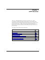
BayRS Version 14.00
Part No. 308634-14.00 Rev 00
September 1999
4401 Great America Parkway
Santa Clara, CA 95054
Configuring L2TP Services
Copyright © 1999 Nortel Networks
All rights reserved. Printed in the USA. September 1999.
The information in this document is subject to change without notice. The statements, configurations, technical data,
and recommendations in this document are believed to be accurate and reliable, but are presented without express or
implied warranty. Users must take full responsibility for their applications of any products specified in this document.
The information in this document is proprietary to Nortel Networks NA Inc.
The software described in this document is furnished under a license agreement and may only be used in accordance
with the terms of that license. A summary of the Software License is included in this document.
Trademarks
NORTEL NETWORKS is a trademark of Nortel Networks.
Bay Networks, AN, BCN, BLN, and BN are registered trademarks and Advanced Remote Node, ARN, ASN, BayRS,
BaySecure Access Control, BayStack, BSAC, and RAC are trademarks of Nortel Networks.
Microsoft, MS, MS-DOS, Win32, Windows, and Windows NT are registered trademarks of Microsoft Corporation.
All other trademarks and registered trademarks are the property of their respective owners.
Restricted Rights Legend
Use, duplication, or disclosure by the United States Government is subject to restrictions as set forth in subparagraph
(c)(1)(ii) of the Rights in Technical Data and Computer Software clause at DFARS 252.227-7013.
Notwithstanding any other license agreement that may pertain to, or accompany the delivery of, this computer
software, the rights of the United States Government regarding its use, reproduction, and disclosure are as set forth in
the Commercial Computer Software-Restricted Rights clause at FAR 52.227-19.
Statement of Conditions
In the interest of improving internal design, operational function, and/or reliability, Nortel Networks NA Inc. reserves
the right to make changes to the products described in this document without notice.
Nortel Networks NA Inc. does not assume any liability that may occur due to the use or application of the product(s)
or circuit layout(s) described herein.
Portions of the code in this software product may be Copyright © 1988, Regents of the University of California. All
rights reserved. Redistribution and use in source and binary forms of such portions are permitted, provided that the
above copyright notice and this paragraph are duplicated in all such forms and that any documentation, advertising
materials, and other materials related to such distribution and use acknowledge that such portions of the software were
developed by the University of California, Berkeley. The name of the University may not be used to endorse or
promote products derived from such portions of the software without specific prior written permission.
SUCH PORTIONS OF THE SOFTWARE ARE PROVIDED “AS IS” AND WITHOUT ANY EXPRESS OR
IMPLIED WARRANTIES, INCLUDING, WITHOUT LIMITATION, THE IMPLIED WARRANTIES OF
MERCHANTABILITY AND FITNESS FOR A PARTICULAR PURPOSE.
In addition, the program and information contained herein are licensed only pursuant to a license agreement that
contains restrictions on use and disclosure (that may incorporate by reference certain limitations and notices imposed
by third parties).
ii
308634-14.00 Rev 00
Nortel Networks NA Inc. Software License Agreement
NOTICE: Please carefully read this license agreement before copying or using the accompanying software or
installing the hardware unit with pre-enabled software (each of which is referred to as “Software” in this Agreement).
BY COPYING OR USING THE SOFTWARE, YOU ACCEPT ALL OF THE TERMS AND CONDITIONS OF
THIS LICENSE AGREEMENT. THE TERMS EXPRESSED IN THIS AGREEMENT ARE THE ONLY TERMS
UNDER WHICH NORTEL NETWORKS WILL PERMIT YOU TO USE THE SOFTWARE. If you do not accept
these terms and conditions, return the product, unused and in the original shipping container, within 30 days of
purchase to obtain a credit for the full purchase price.
1. License Grant. Nortel Networks NA Inc. (“Nortel Networks”) grants the end user of the Software (“Licensee”) a
personal, nonexclusive, nontransferable license: a) to use the Software either on a single computer or, if applicable, on
a single authorized device identified by host ID, for which it was originally acquired; b) to copy the Software solely
for backup purposes in support of authorized use of the Software; and c) to use and copy the associated user manual
solely in support of authorized use of the Software by Licensee. This license applies to the Software only and does not
extend to Nortel Networks Agent software or other Nortel Networks software products. Nortel Networks Agent
software or other Nortel Networks software products are licensed for use under the terms of the applicable Nortel
Networks NA Inc. Software License Agreement that accompanies such software and upon payment by the end user of
the applicable license fees for such software.
2. Restrictions on use; reservation of rights. The Software and user manuals are protected under copyright laws.
Nortel Networks and/or its licensors retain all title and ownership in both the Software and user manuals, including
any revisions made by Nortel Networks or its licensors. The copyright notice must be reproduced and included with
any copy of any portion of the Software or user manuals. Licensee may not modify, translate, decompile, disassemble,
use for any competitive analysis, reverse engineer, distribute, or create derivative works from the Software or user
manuals or any copy, in whole or in part. Except as expressly provided in this Agreement, Licensee may not copy or
transfer the Software or user manuals, in whole or in part. The Software and user manuals embody Nortel Networks’
and its licensors’ confidential and proprietary intellectual property. Licensee shall not sublicense, assign, or otherwise
disclose to any third party the Software, or any information about the operation, design, performance, or
implementation of the Software and user manuals that is confidential to Nortel Networks and its licensors; however,
Licensee may grant permission to its consultants, subcontractors, and agents to use the Software at Licensee’s facility,
provided they have agreed to use the Software only in accordance with the terms of this license.
3. Limited warranty. Nortel Networks warrants each item of Software, as delivered by Nortel Networks and properly
installed and operated on Nortel Networks hardware or other equipment it is originally licensed for, to function
substantially as described in its accompanying user manual during its warranty period, which begins on the date
Software is first shipped to Licensee. If any item of Software fails to so function during its warranty period, as the sole
remedy Nortel Networks will at its discretion provide a suitable fix, patch, or workaround for the problem that may be
included in a future Software release. Nortel Networks further warrants to Licensee that the media on which the
Software is provided will be free from defects in materials and workmanship under normal use for a period of 90 days
from the date Software is first shipped to Licensee. Nortel Networks will replace defective media at no charge if it is
returned to Nortel Networks during the warranty period along with proof of the date of shipment. This warranty does
not apply if the media has been damaged as a result of accident, misuse, or abuse. The Licensee assumes all
responsibility for selection of the Software to achieve Licensee’s intended results and for the installation, use, and
results obtained from the Software. Nortel Networks does not warrant a) that the functions contained in the software
will meet the Licensee’s requirements, b) that the Software will operate in the hardware or software combinations that
the Licensee may select, c) that the operation of the Software will be uninterrupted or error free, or d) that all defects
in the operation of the Software will be corrected. Nortel Networks is not obligated to remedy any Software defect that
cannot be reproduced with the latest Software release. These warranties do not apply to the Software if it has been (i)
altered, except by Nortel Networks or in accordance with its instructions; (ii) used in conjunction with another
vendor’s product, resulting in the defect; or (iii) damaged by improper environment, abuse, misuse, accident, or
negligence. THE FOREGOING WARRANTIES AND LIMITATIONS ARE EXCLUSIVE REMEDIES AND ARE
IN LIEU OF ALL OTHER WARRANTIES EXPRESS OR IMPLIED, INCLUDING WITHOUT LIMITATION ANY
WARRANTY OF MERCHANTABILITY OR FITNESS FOR A PARTICULAR PURPOSE. Licensee is responsible
308634-14.00 Rev 00
iii
for the security of its own data and information and for maintaining adequate procedures apart from the Software to
reconstruct lost or altered files, data, or programs.
4. Limitation of liability. IN NO EVENT WILL NORTEL NETWORKS OR ITS LICENSORS BE LIABLE FOR
ANY COST OF SUBSTITUTE PROCUREMENT; SPECIAL, INDIRECT, INCIDENTAL, OR CONSEQUENTIAL
DAMAGES; OR ANY DAMAGES RESULTING FROM INACCURATE OR LOST DATA OR LOSS OF USE OR
PROFITS ARISING OUT OF OR IN CONNECTION WITH THE PERFORMANCE OF THE SOFTWARE, EVEN
IF NORTEL NETWORKS HAS BEEN ADVISED OF THE POSSIBILITY OF SUCH DAMAGES. IN NO EVENT
SHALL THE LIABILITY OF NORTEL NETWORKS RELATING TO THE SOFTWARE OR THIS AGREEMENT
EXCEED THE PRICE PAID TO NORTEL NETWORKS FOR THE SOFTWARE LICENSE.
5. Government Licensees. This provision applies to all Software and documentation acquired directly or indirectly by
or on behalf of the United States Government. The Software and documentation are commercial products, licensed on
the open market at market prices, and were developed entirely at private expense and without the use of any U.S.
Government funds. The license to the U.S. Government is granted only with restricted rights, and use, duplication, or
disclosure by the U.S. Government is subject to the restrictions set forth in subparagraph (c)(1) of the Commercial
Computer Software––Restricted Rights clause of FAR 52.227-19 and the limitations set out in this license for civilian
agencies, and subparagraph (c)(1)(ii) of the Rights in Technical Data and Computer Software clause of DFARS
252.227-7013, for agencies of the Department of Defense or their successors, whichever is applicable.
6. Use of Software in the European Community. This provision applies to all Software acquired for use within the
European Community. If Licensee uses the Software within a country in the European Community, the Software
Directive enacted by the Council of European Communities Directive dated 14 May, 1991, will apply to the
examination of the Software to facilitate interoperability. Licensee agrees to notify Nortel Networks of any such
intended examination of the Software and may procure support and assistance from Nortel Networks.
7. Term and termination. This license is effective until terminated; however, all of the restrictions with respect to
Nortel Networks’ copyright in the Software and user manuals will cease being effective at the date of expiration of the
Nortel Networks copyright; those restrictions relating to use and disclosure of Nortel Networks’ confidential
information shall continue in effect. Licensee may terminate this license at any time. The license will automatically
terminate if Licensee fails to comply with any of the terms and conditions of the license. Upon termination for any
reason, Licensee will immediately destroy or return to Nortel Networks the Software, user manuals, and all copies.
Nortel Networks is not liable to Licensee for damages in any form solely by reason of the termination of this license.
8. Export and Re-export. Licensee agrees not to export, directly or indirectly, the Software or related technical data
or information without first obtaining any required export licenses or other governmental approvals. Without limiting
the foregoing, Licensee, on behalf of itself and its subsidiaries and affiliates, agrees that it will not, without first
obtaining all export licenses and approvals required by the U.S. Government: (i) export, re-export, transfer, or divert
any such Software or technical data, or any direct product thereof, to any country to which such exports or re-exports
are restricted or embargoed under United States export control laws and regulations, or to any national or resident of
such restricted or embargoed countries; or (ii) provide the Software or related technical data or information to any
military end user or for any military end use, including the design, development, or production of any chemical,
nuclear, or biological weapons.
9. General. If any provision of this Agreement is held to be invalid or unenforceable by a court of competent
jurisdiction, the remainder of the provisions of this Agreement shall remain in full force and effect. This Agreement
will be governed by the laws of the state of California.
Should you have any questions concerning this Agreement, contact Nortel Networks, 4401 Great America Parkway,
P.O. Box 58185, Santa Clara, California 95054-8185.
LICENSEE ACKNOWLEDGES THAT LICENSEE HAS READ THIS AGREEMENT, UNDERSTANDS IT, AND
AGREES TO BE BOUND BY ITS TERMS AND CONDITIONS. LICENSEE FURTHER AGREES THAT THIS
AGREEMENT IS THE ENTIRE AND EXCLUSIVE AGREEMENT BETWEEN NORTEL NETWORKS AND
LICENSEE, WHICH SUPERSEDES ALL PRIOR ORAL AND WRITTEN AGREEMENTS AND
COMMUNICATIONS BETWEEN THE PARTIES PERTAINING TO THE SUBJECT MATTER OF THIS
AGREEMENT. NO DIFFERENT OR ADDITIONAL TERMS WILL BE ENFORCEABLE AGAINST NORTEL
NETWORKS UNLESS NORTEL NETWORKS GIVES ITS EXPRESS WRITTEN CONSENT, INCLUDING AN
EXPRESS WAIVER OF THE TERMS OF THIS AGREEMENT.
iv
308634-14.00 Rev 00
Contents
Preface
Before You Begin .............................................................................................................xiii
Text Conventions .............................................................................................................xiv
Acronyms ......................................................................................................................... xv
Hard-Copy Technical Manuals .........................................................................................xvi
How to Get Help .............................................................................................................xvii
Chapter 1
L2TP Overview
L2TP Benefits .................................................................................................................1-2
What Is Tunneling? .........................................................................................................1-2
L2TP Sessions .........................................................................................................1-3
Components of an L2TP Network ..................................................................................1-4
Remote Host ............................................................................................................1-4
L2TP Access Concentrator (LAC) ............................................................................1-5
Remote Access Server (RAS) ..................................................................................1-5
Tunnel Management Server (TMS) ..........................................................................1-5
L2TP Network Server (LNS) ....................................................................................1-6
RADIUS Server ........................................................................................................1-6
Examples of L2TP Networks ....................................................................................1-7
L2TP Packet Encapsulation ............................................................................................1-8
Making a Connection Across an L2TP Network .............................................................1-9
Security in an L2TP Network ........................................................................................1-10
Nortel Networks L2TP Implementation .........................................................................1-11
Tunnel Management ...............................................................................................1-12
Tunnel Authentication .............................................................................................1-12
RADIUS User Authentication .................................................................................1-14
RADIUS Accounting ...............................................................................................1-15
L2TP IP Interface Addresses .................................................................................1-15
308634-14.00 Rev 00
v
Remote Router Configuration ................................................................................1-16
Framed Routes .......................................................................................................1-17
Configuring the Framed-Route Feature ...........................................................1-18
Name Server Addresses ........................................................................................1-19
Configuring the NSA Feature on the LNS ........................................................1-21
Example: Name Server Address Origin Parameter Set to Local .....................1-22
Example: Name Server Address Origin Parameter Set to RADIUS ................1-24
Checking NSA Assignments from the Remote Host ........................................1-26
Where to Go Next .........................................................................................................1-29
Chapter 2
Starting L2TP
Planning Considerations for an L2TP Network ...............................................................2-2
Tunnel Authentication Passwords .............................................................................2-2
RADIUS Server Information .....................................................................................2-2
Preparing a Configuration File ........................................................................................2-3
Enabling L2TP on an Unconfigured WAN Interface ........................................................2-4
Enabling L2TP on an Existing PPP Interface .................................................................2-5
Enabling L2TP on an Existing Frame Relay Interface ....................................................2-7
Enabling L2TP on an Existing ATM Interface ..................................................................2-9
Chapter 3
Customizing L2TP Services
Modifying the L2TP Protocol Configuration ....................................................................3-2
Modifying RADIUS Server Information ...........................................................................3-3
Changing the LNS System Name ...................................................................................3-4
Modifying the Number of L2TP Sessions Permitted .......................................................3-5
Keeping the Remote User’s Domain Name ....................................................................3-6
Changing the Domain Name Delimiter ...........................................................................3-7
Enabling Tunnel Authentication .......................................................................................3-8
Configuring the Name Server Address Feature .............................................................3-9
Modifying L2TP IP Interface Addresses .......................................................................3-10
Disabling RIP ................................................................................................................3-11
Disabling L2TP .............................................................................................................3-11
Deleting L2TP from a PPP Interface .............................................................................3-12
Deleting L2TP from a Frame Relay Interface ................................................................3-13
vi
308634-14.00 Rev 00
Deleting L2TP from an ATM Interface ...........................................................................3-14
Appendix A
L2TP Parameters
L2TP Configuration Parameters .................................................................................... A-2
L2TP Tunnel Security Parameters ............................................................................... A-10
L2TP IP Interface Parameters ..................................................................................... A-12
Appendix B
Configuration Examples
Example 1: Remote PC Calling the Corporate Network ................................................ B-1
Configuring the Remote Hosts ................................................................................ B-2
Configuring the Model 5399 as a LAC .................................................................... B-3
Configuring the TMS ............................................................................................... B-4
Configuring the RADIUS Server ............................................................................. B-5
Configuring the LNS ................................................................................................ B-7
Configuring the ISP Router ..................................................................................... B-8
Data Path Through the Network .............................................................................. B-9
Example 2: Remote Router Calling the Corporate Network ........................................ B-10
Configuring the Dial-on-Demand Remote Router ................................................. B-11
Configuring the Model 5399 as a LAC .................................................................. B-14
Configuring the TMS ............................................................................................. B-15
Configuring the RADIUS Server ........................................................................... B-16
Configuring the LNS .............................................................................................. B-18
Configuring the ISP Router ................................................................................... B-19
Appendix C
Troubleshooting
Index
308634-14.00 Rev 00
vii
Figures
Figure 1-1.
L2TP Network Using a LAC .....................................................................1-7
Figure 1-2.
L2TP Network Using a RAS .....................................................................1-7
Figure 1-3.
Packet Encapsulation Process .................................................................1-8
Figure 1-4.
Tunnel Authentication Control Messages ...............................................1-13
Figure 1-5.
Remote Router Dialing the LNS .............................................................1-16
Figure 1-6.
L2TP Network Without Framed-Route Support .....................................1-17
Figure 1-7.
L2TP Network with Framed-Route Support ...........................................1-18
Figure 1-8.
TCP/IP Settings Window for Server-Assigned NSAs .............................1-20
Figure 1-9.
Network with Local Name Server Address Origin ..................................1-23
Figure 1-10. Network with RADIUS Name Server Address Origin .............................1-25
Figure 1-11. Run Window ...........................................................................................1-26
Figure 1-12. IP Configuration Window .......................................................................1-27
Figure 1-13. More Info. IP Configuration Window .......................................................1-28
Figure A-1.
L2TP Configuration List Window ............................................................. A-2
Figure A-2.
L2TP Tunnel Security List Window ....................................................... A-10
Figure A-3.
L2TP IP Interface List Window .............................................................. A-12
Figure A-4.
L2TP IP Interface Window .................................................................... A-12
Figure B-1.
L2TP Network with PCs at the Remote Site ........................................... B-2
Figure B-2.
L2TP Network with Routers at the Remote Site ................................... B-10
308634-14.00 Rev 00
ix
Tables
Table B-1.
Configuration Commands for the Model 5399 LAC ................................ B-3
Table B-2.
Configuration for the nortelnetworks Domain .......................................... B-4
Table B-3.
Configuration Commands for the Model 5399 LAC .............................. B-14
Table B-4.
Configuration for the nortelnetworks Domain ........................................ B-15
Table C-1.
Common L2TP Network Problems and Solutions ................................... C-1
308634-14.00 Rev 00
xi
Preface
This guide describes Layer 2 Tunneling Protocol (L2TP) and what you do to start
and customize L2TP services on a Nortel Networks™ router.
Before You Begin
Before using this guide, you must complete the following procedures. For a new
router:
•
Install the router (see the installation guide that came with your router).
•
Connect the router to the network and create a configuration file (see
Quick-Starting Routers, Configuring BayStack Remote Access, or Connecting
ASN Routers to a Network).
Make sure that you are running the latest version of Nortel Networks BayRS™ and
Site Manager software. For information about upgrading BayRS and Site
Manager, see the upgrading guide for your version of BayRS.
308634-14.00 Rev 00
xiii
Configuring L2TP Services
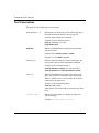
Text Conventions
This guide uses the following text conventions:
angle brackets (< >)
Indicate that you choose the text to enter based on the
description inside the brackets. Do not type the
brackets when entering the command.
Example: If the command syntax is:
ping <ip_address>, you enter:
ping 192.32.10.12
bold text
Indicates command names and options and text that
you need to enter.
Example: Enter show ip {alerts | routes}.
Example: Use the dinfo command.
brackets ([ ])
Indicate optional elements in syntax descriptions. Do
not type the brackets when entering the command.
Example: If the command syntax is:
show ip interfaces [-alerts], you can enter either:
show ip interfaces or show ip interfaces -alerts.
italic text
Indicates file and directory names, new terms, book
titles, and variables in command syntax descriptions.
Where a variable is two or more words, the words are
connected by an underscore.
Example: If the command syntax is:
show at <valid_route>
valid_route is one variable and you substitute one value
for it.
screen text
Indicates system output, for example, prompts and
system messages.
Example: Set Trap Monitor Filters
xiv
308634-14.00 Rev 00
Preface
separator ( > )
Shows menu paths.
Example: Protocols > IP identifies the IP option on the
Protocols menu.
vertical line ( | )
Separates choices for command keywords and
arguments. Enter only one of the choices. Do not type
the vertical line when entering the command.
Example: If the command syntax is:
show ip {alerts | routes}, you enter either:
show ip alerts or show ip routes, but not both.
Acronyms
This guide uses the following acronyms:
BGP
Border Gateway Protocol
CHAP
Challenge Handshake Authentication Protocol
DNS
Domain Name System or domain name server
IP
Internet Protocol
IPCP
IP Control Protocol
ISDN
Integrated Services Digital Network
ISP
Internet service provider
L2TP
Layer 2 Tunneling Protocol
LAC
L2TP access concentrator
LAN
local area network
LCP
Link Control Protocol
LNS
L2TP network server
MPPP
Multilink Point-to-Point Protocol
NSA
name server address
OSPF
Open Shortest Path First
PAP
Password Authentication Protocol
PPP
Point-to-Point Protocol
308634-14.00 Rev 00
xv
Configuring L2TP Services
RADIUS
Remote Authentication Dial-In User Service
RAS
remote access server
RIP
Routing Information Protocol
SCCCN
start control connection connected
SCCRP
start control connection reply
SCCRQ
start control connection request
TA
terminal adapter
TCP/IP
Transmission Control Protocol/Internet Protocol
TMS
tunnel management server
UDP
User Datagram Protocol
VPN
virtual private network
VSA
vendor-specific attribute
WAN
wide area network
Hard-Copy Technical Manuals
You can print selected technical manuals and release notes free, directly from the
Internet. Go to support.baynetworks.com/library/tpubs/. Find the product for
which you need documentation. Then locate the specific category and model or
version for your hardware or software product. Using Adobe Acrobat Reader, you
can open the manuals and release notes, search for the sections you need, and print
them on most standard printers. You can download Acrobat Reader free from the
Adobe Systems Web site, www.adobe.com.
You can purchase selected documentation sets, CDs, and technical publications
through the collateral catalog. The catalog is located on the World Wide Web at
support.baynetworks.com/catalog.html and is divided into sections arranged
alphabetically:
xvi
•
The “CD ROMs” section lists available CDs.
•
The “Guides/Books” section lists books on technical topics.
•
The “Technical Manuals” section lists available printed documentation sets.
308634-14.00 Rev 00
Preface
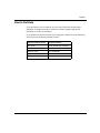
How to Get Help
If you purchased a service contract for your Nortel Networks product from a
distributor or authorized reseller, contact the technical support staff for that
distributor or reseller for assistance.
If you purchased a Nortel Networks service program, contact one of the following
Nortel Networks Technical Solutions Centers:
Technical Solutions Center
Telephone Number
Billerica, MA
800-2LANWAN (800-252-6926)
Santa Clara, CA
800-2LANWAN (800-252-6926)
Valbonne, France
33-4-92-96-69-68
Sydney, Australia
61-2-9927-8800
Tokyo, Japan
81-3-5402-7041
308634-14.00 Rev 00
xvii
Chapter 1
L2TP Overview
The Layer 2 Tunneling Protocol (L2TP) provides remote users, such as
telecommuters, mobile professionals, and personnel in remote branch offices,
with dial-in access to a corporate network. L2TP enables users to create a virtual
private network (VPN). A VPN uses the existing physical infrastructure of a
public network, such as the Internet, but offers the security and exclusivity of a
private network.
This chapter contains the following information:
Topic
Page
L2TP Benefits
1-2
What Is Tunneling?
1-2
Components of an L2TP Network
1-4
L2TP Packet Encapsulation
1-8
Making a Connection Across an L2TP Network
1-9
Security in an L2TP Network
1-10
Nortel Networks L2TP Implementation
1-11
Where to Go Next
1-29
308634-14.00 Rev 00
1-1
Configuring L2TP Services
L2TP Benefits
L2TP provides the following benefits to remote users, corporations, and ISPs:
•
Users and businesses can take advantage of existing network equipment and
resources.
Corporations do not need to maintain and manage remote access servers and
other special networking equipment for remote users. Instead, they can use
their existing Internet leased connections and resources at the Internet service
provider (ISP) network, thereby significantly reducing corporate networking
and maintenance costs.
In addition, corporations do not need to provide technical support to the
remote users. Because the remote user is making a local call to the ISP, the
ISP provides technical assistance if the user has trouble making connections.
•
Remote users can place a free local call to their ISP for access to the Internet,
eliminating long-distance toll calls required to dial the corporate network
directly.
•
ISPs earn more business from corporate customers using the equipment,
thereby increasing the ISP’s revenues.
•
L2TP is a standards-based protocol that provides greater interoperability with
networking equipment from other vendors.
What Is Tunneling?
Tunneling is a way of forwarding traffic from remote users to a corporate network
through an IP network. A tunnel is a virtual connection between two sites, for
example, an access concentrator at the ISP network and a router at the corporate
network. Tunneling across an existing public network such as the Internet creates
a virtual private network that offers corporate network access to a wider range of
remote users.
L2TP is a tunneling mechanism that extends the end point of the Point-to-Point
Protocol (PPP) connection from an L2TP access concentrator (LAC) or remote
access server (RAS) at the ISP network to an L2TP network server (LNS) at the
corporate site.
1-2
308634-14.00 Rev 00
L2TP Overview
Multiple users can communicate through a single tunnel between the same LAC
and LNS pair. Each user transmits and receives data in an individual L2TP
session.
The LAC brings down the tunnel for any one of the following reasons:
•
A network failure occurs.
•
The LAC or other equipment at the ISP is not operating properly. If the LAC
fails, all tunnel users are disconnected.
•
There are no active sessions inside the tunnel.
An individual session ends when a remote user disconnects the call, but
multiple sessions can run inside a single tunnel.
•
The system administrator at the ISP terminates the user connection.
•
The LAC is not responding to a Hello packet from the LNS.
For the LAC to reestablish a tunnel, the remote user has to place a new call.
L2TP Sessions
Packets are exchanged across an L2TP tunnel during an L2TP session. An L2TP
session is created when an end-to-end WAN connection is established between the
remote host and the LNS.
The L2TP portion of the packets sent through the tunnel contains a header with a
call ID field (also called a session ID) and a tunnel ID field. The call ID field,
which indicates the session that the WAN packet belongs to, is negotiated between
the LAC and the LNS when the L2TP call is set up. The tunnel ID specifies the
tunnel that the L2TP session is using.
In addition to the fields in the header, the L2TP packet contains a call serial
number, which is a unique number for each L2TP call. This number matches the
call to the L2TP session.
You can enable flow control for an L2TP session. Flow control manages
congestion across the connection, ensures that packets are not lost, and makes sure
that the devices at each end of the connection are communicating properly.
To enable flow control, see “Modifying the L2TP Protocol Configuration” on
page 3-2.
308634-14.00 Rev 00
1-3
Configuring L2TP Services
Components of an L2TP Network
The following sections describe the components of an L2TP network. For
illustrations of L2TP networks, see Figures 1-1 and 1-2 on page 1-7.
Remote Host
At the remote site is the user who wants to dial in to the corporate network. The
remote user can be located anywhere, provided that the user can dial into an ISP
network using a PC or a router. The ISP provides the connection to the Internet.
The host at the remote site can be a PC or router that uses PPP for dial-up
connections.
•
If the PC or router does not have built-in L2TP software capabilities, it dials
into a LAC, which provides a tunnel across the Internet to the corporate LNS.
•
If the PC or router is an L2TP client, that is, it has built-in L2TP functionality,
the L2TP client software provides a tunnel through a RAS across the Internet
to the corporate LNS. A LAC is unnecessary with an L2TP client.
The main difference between connecting an L2TP client and a nonclient is the
starting point of the tunnel. For an L2TP client, the tunnel begins at the PC or
router; for a non-L2TP client, the tunnel begins at the LAC. All tunnels end at the
LNS.
Note: This guide’s primary focus is on an L2TP network between a remote
host that does not have built-in L2TP capabilities and uses a LAC, rather than a
RAS.
1-4
308634-14.00 Rev 00
L2TP Overview
L2TP Access Concentrator (LAC)
The L2TP access concentrator (LAC) resides at the ISP network. The LAC
establishes the L2TP tunnel between itself and the LNS.
Note: In this guide, the term LAC refers to a remote access server with L2TP
capabilities. The term RAS refers to a remote access server without L2TP
capabilities.
When the remote user places a call to the ISP network, this call goes to the LAC.
The LAC then negotiates the activation of an L2TP tunnel with the LNS. This
tunnel carries data from the remote user to the corporate network.
For more information about the Nortel Networks implementation of the LAC in an
L2TP network, see “Nortel Networks L2TP Implementation” on page 1-11.
Remote Access Server (RAS)
The remote access server (RAS) resides at the ISP network. If the remote host is
an L2TP client, the tunnel is established from the remote client through a RAS to
an LNS at the corporate network. In this situation, there is no need for a LAC.
The RAS does not establish the tunnel; it only forwards already tunneled data to
the destination.
Tunnel Management Server (TMS)
The ISP network must provide a mechanism for identifying L2TP tunneled users
so that the LAC can construct the L2TP tunnel. Nortel Networks uses a
mechanism called a tunnel management server (TMS); other vendors may use a
different method.
308634-14.00 Rev 00
1-5
Configuring L2TP Services
L2TP Network Server (LNS)
The L2TP network server (LNS) is a router that resides at the corporate network
and serves as the termination point for L2TP tunnels and sessions.
The LNS authenticates the PPP connection request and allows the end-to-end PPP
tunneled connection. The LNS may also perform user authentication with a
RADIUS server to prevent unauthorized users from accessing the network;
however, user authentication may also be done by the LNS itself.
An LNS can support multiple remote users, each communicating within their own
L2TP session. The L2TP session is the virtual end-to-end connection over which
the LAC sends data to the LNS.
The Nortel Networks router is an LNS. For information about the Nortel
Networks LNS, see “Nortel Networks L2TP Implementation” on page 1-11.
RADIUS Server
An L2TP network may include a Remote Authentication Dial-in User Service
(RADIUS) server. The RADIUS server has three main functions in an L2TP
network:
•
Authenticating the remote users
•
Assigning IP addresses to the remote users
•
Providing accounting services for corporate billing
The RADIUS server database centralizes the authentication function, eliminating
the need to configure each LNS with user names and passwords. It also assigns an
IP address to a remote host to identify the host. Finally, the RADIUS server can
provide accounting services for the corporate network, calculating billing charges
for an L2TP session.
For information about the Nortel Networks implementation of RADIUS user
authentication and accounting, see “RADIUS User Authentication” on page 1-14
and “RADIUS Accounting” on page 1-15.
1-6
308634-14.00 Rev 00
L2TP Overview
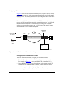
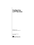
Examples of L2TP Networks
Figure 1-1 shows an L2TP network that uses a LAC to connect to the LNS. The
tunnel is between the LAC and the LNS.
ISP network
PC
Frame relay
connection
LAC
Remote
host
LNS
Tunnel
PPP
connection
Corporate network
Data
RADIUS
server
No L2TP
functionality
TMS
L2T0003A
Figure 1-1.
L2TP Network Using a LAC
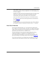
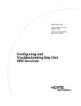
Figure 1-2 shows an L2TP network that uses a RAS to connect to the LNS. The
tunnel is between the PC (the L2TP client) and the LNS.
ISP network
Remote
host
Frame relay
connection
RAS
Corporate network
LNS
Tunnel
PC
Data
RADIUS
server
L2TP
client
L2T0004A
Figure 1-2.
L2TP Network Using a RAS
308634-14.00 Rev 00
1-7
Configuring L2TP Services
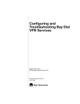
L2TP Packet Encapsulation
The PC or router at the remote site sends PPP packets to the LAC. The LAC
encapsulates these incoming packets in an L2TP packet and sends it across an IP
network through a bidirectional tunnel. After the LNS receives the packets, it
decapsulates them and terminates the PPP connection.
Figure 1-3 shows how data is encapsulated for transmission over an L2TP
network.
Remote user places a call
PPP
IP
DATA
LAC
Layer 2
protocol
IP/UDP
PPP
L2TP
IP
DATA
LNS
IP
DATA
Data packet moves to the corporate network
L2T0005A
Figure 1-3.
1-8
Packet Encapsulation Process
308634-14.00 Rev 00
L2TP Overview
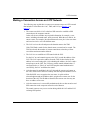
Making a Connection Across an L2TP Network
The following steps explain how a remote user connects across an L2TP network
that includes a Nortel Networks LAC, TMS, and LNS (see Figure 1-1 on
page 1-7):
1.
The remote user dials a LAC at the local ISP network to establish a PPP
connection to the corporate network.
In the call, the user includes any required information, for example, a user
name, including a domain name, and a password. When the user dials in, he
enters a name, for example, [email protected]; jdoe is the user name
and nortelnetworks.com is the domain name.
2.
The LAC receives the call and passes the domain name to the TMS.
If the TMS finds a match for the domain name, a tunnel can be created. The
TMS also checks the number of current connections so that they will not
exceed the maximum number allowed.
3.
The LAC tries to establish an L2TP tunnel with the LNS.
For the LAC to send a tunnel request to the LNS, it needs the address of the
LNS. The LAC requests the address from the TMS. It then checks for this
address in its own routing table. After obtaining the address, the LAC sends a
tunnel request to the LNS. The LNS may perform tunnel authentication, if
configured to do so. If the LAC and LNS complete tunnel authentication
successfully, the LAC establishes the tunnel.
4.
After the tunnel is established, the LAC forwards the remote user’s name to
the LNS, which verifies the user’s identity with the corporate RADIUS server.
If the RADIUS server recognizes the user name, it replies with an
acknowledgment and an IP address that it assigns to the remote user for the
duration of the call. This IP address identifies the remote user who may not
have an address of her own.
5.
After the remote user is successfully authenticated, the user has an end-to-end
PPP connection to the corporate network over the Internet.
The tunnel can now carry a user session during which the LAC and the LNS
exchange PPP packets.
308634-14.00 Rev 00
1-9
Configuring L2TP Services
Security in an L2TP Network
You can configure two layers of security in an L2TP network:
•
Tunnel authentication
Tunnel authentication is the process of negotiating the establishment of a
tunnel between the LAC and the LNS.
•
User authentication
The network administrator at the corporate site can configure a RADIUS
server with the names and passwords of authorized users. The server’s
database centralizes the authentication function, eliminating the need to
configure each LNS with user names and passwords.
When the LNS receives a call, it forwards the user information to the
RADIUS server, which verifies whether the user is authorized to access the
network.
For more information about the Nortel Networks implementation of tunnel and
user authentication, see “Tunnel Authentication” on page 1-12 and “RADIUS
User Authentication” on page 1-14.
1-10
308634-14.00 Rev 00
L2TP Overview
Nortel Networks L2TP Implementation
In an L2TP network, the Nortel Networks router is the LNS. LNS software
operates on the following routers:
•
•
•
BayStack™ Access Node (AN®) and Advanced Remote Node™ (ARN™)
Backbone Link Node (BLN®) and Backbone Concentrator Node (BCN®)
Access Stack Node (ASN™)
The Nortel Networks LNS has the following characteristics:
•
Each slot can act as an LNS, which means that one router can have many LNS
interfaces, each with its own address. You can have as many LNS interfaces as
there are available slots on the router.
•
The LNS performs user authentication with a RADIUS server to prevent
unauthorized users from accessing the network.
•
The LNS accepts only incoming calls; it does not place calls to the LAC.
•
The Nortel Networks L2TP implementation supports only IP traffic through
the L2TP tunnel. The LNS supports only numbered IP addresses.
•
The router interface between the ISP and the corporate network (see
Figure 1-1 on page 1-7) is a leased line operating with frame relay, PPP
(including PPP multilink), or ATM. Nortel Networks recommends that you
use a high-speed link, such as T1, for the leased connection.
•
The LNS terminates PPP multilink and PPP encapsulated data within an
L2TP packet.
•
The LNS operates with the LAC implementation configured on the Nortel
Networks Model 5399 Remote Access Concentrator (RAC™).
•
The host (PC or router) dialing into the ISP network can be on the same
subnet as the IP interface on the LNS.
•
The LNS supports the Routing Information Protocol (RIP). RIP is particularly
useful when the remote host is a router, because it enables the LNS to learn
routing information from the remote router.
For instructions on how to configure a Nortel Networks router as an LNS, see
Chapter 2, “Starting L2TP.”
308634-14.00 Rev 00
1-11
Configuring L2TP Services
Tunnel Management
The Nortel Networks tunnel management server (TMS), which resides at the ISP
network, stores the TMS database. This database contains the remote users’
domain name, the IP address information of each LNS, and other tunnel
addressing information that the network administrator configures. The LAC
requests this information from the TMS to construct the L2TP tunnel.
When the LAC receives a call, it forwards the domain name to the TMS. The
domain name is the portion of the user’s address that specifies a particular location
in the network. For example, if the user name is [email protected],
nortelnetworks.com is the domain name. The TMS looks up the domain name and
verifies that the remote user is an L2TP user. The TMS also provides the LAC
with the addressing information required to establish a tunnel to the correct LNS.
Note: The domain name referred to in this guide is a domain identifier that
does not follow a specific format. It is not related to any Domain Name System
(DNS) protocol requirements.
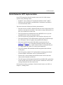
Tunnel Authentication
For security purposes, you can enable the LNS to perform tunnel authentication.
Tunnel authentication is the process of negotiating the establishment of a tunnel.
During tunnel authentication, the LNS identifies the LAC or L2TP client by
comparing the LAC’s tunnel authentication password with its own password. If
the passwords match, the LNS permits the LAC to establish a tunnel.
The LAC does not send the tunnel authentication password as a plain-text
message. The exchange of passwords works much like the PPP Challenge
Handshake Authentication Protocol (CHAP). When one side receives a challenge,
it responds with a value that is calculated based on the authentication password.
The receiving side matches the value against its own calculation. If the values
match, authentication is successful.
Tunnel authentication occurs in both directions, which means that the LAC and
LNS both try to verify the other’s identity.
1-12
308634-14.00 Rev 00
L2TP Overview
You can enable tunnel authentication on the Nortel Networks LNS. If tunnel
authentication is disabled, which is the default, the LNS sends a default challenge
response to the LAC during the authentication process so that the tunnel can be
established. The LNS cannot send outgoing calls, so it cannot initiate tunnel
authentication.
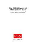
During tunnel authentication, the following exchange of messages takes place:
1.
The LAC sends a tunnel setup message, called the start control connection
request (SCCRQ) message to the LNS. This message includes a challenge to
the LNS.
2.
The LNS replies with a tunnel response, a challenge response, and its own
challenge message. This is called the start control connection reply (SCCRP)
message.
3.
The LAC replies with a challenge response that includes its tunnel
authentication password. This is the start control connection connected
(SCCCN) message.
4.
If this same password is configured for the LNS, the LNS grants approval to
the LAC to establish a tunnel.
Figure 1-4 shows tunnel authentication.
ISP network
Corporate network
PPP connection
LNS
LAC
SCCRQ
tunnel request and challenge
SCCRP
tunnel response, challenge response,
and LNS challenge
SCCCN
challenge response
L2T0006A
Figure 1-4.
308634-14.00 Rev 00
Tunnel Authentication Control Messages
1-13
Configuring L2TP Services
After tunnel authentication is complete, it does not need to be repeated for other
calls to the same LAC.
RADIUS User Authentication
RADIUS user authentication is enabled by default on the Nortel Networks LNS;
you must configure this feature so that the LNS can validate the remote user’s
identity before allowing access to the network.
The network administrator at the corporate site must configure a RADIUS server
with the names and passwords of authorized users. If the corporate network uses
an existing RADIUS database for L2TP connections, you do not need to
reconfigure the names in the database.
When the LNS receives a call, it forwards an authentication request with the user
information to the RADIUS server, which verifies whether the user is authorized.
If the user is permitted access to the network, the RADIUS server replies with an
acknowledgment message and the appropriate IP address for that user to make a
connection.
The IP address that the RADIUS server assigns is essential because many remote
hosts may not have their own addresses. The LNS uses the address to identify the
remote host and send data to the remote user. After the session ends, the IP
address becomes available for another user.
The LNS automatically removes the domain portion of the user name that is
included as part of the call from the LAC to the LNS. If you want to keep the
domain name, you can disable this feature. For instructions, see “Keeping the
Remote User’s Domain Name” on page 3-6.
For more information about configuring Nortel Networks routers as RADIUS
clients, see Configuring RADIUS.
1-14
308634-14.00 Rev 00
L2TP Overview
RADIUS Accounting
The RADIUS server can provide accounting services in addition to its
authentication services. RADIUS accounting is enabled by default on the Nortel
Networks LNS.
The RADIUS accounting server calculates billing charges for an L2TP session
between the remote user and the LNS. To determine these charges, the server uses
information that it receives from the LNS, such as the status of each call and the
number of packets sent during the session. Using this data, the server determines
billing charges, which the network administrator can use to manage network costs.
The primary RADIUS accounting server can be the same server as the
authentication server or it can be a different server.
For more information about RADIUS accounting, see Configuring RADIUS.
L2TP IP Interface Addresses
When configuring the Nortel Networks LNS, you must configure an IP address
for every slot that has an L2TP interface. This address is referred to as the L2TP
IP interface address. The L2TP IP interface can be any valid IP address.
The L2TP IP interface address is internal to the LNS. When communicating with
the remote user, the LNS associates the user’s IP address, which is assigned by the
RADIUS server, with the L2TP IP interface address that you configured.
The L2TP IP interface address and the RADIUS-assigned IP address do not need
to be in the same subnet.
308634-14.00 Rev 00
1-15
Configuring L2TP Services
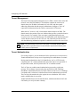
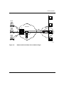
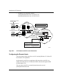
Remote Router Configuration
If the host at the remote site is a Nortel Networks router, you may need to
configure a dial-on-demand circuit for the remote router’s dial-up interface to the
LAC at the ISP network.
Enable RIP on both the dial-on-demand circuit and the attached LAN interface of
the remote router, so that the LNS can learn routing information from the remote
router. To avoid unnecessarily activating the circuit because of RIP packets, enable
dial-optimized routing for the dial-on-demand circuit (see Figure 1-5).
Also, configure a default or static route on the remote router, which uses the
next-hop address that corresponds to the L2TP IP interface address of the LNS.
This default or static route enables the remote router to deliver L2TP packets to
the LNS.
LAC
192.168.18.41
PC 1
Dial-in router
LNS
192.168.19.34
192.32.25.34
PC 2
192.32.25.35
LAN interface Dial-on-demand
RIP enabled RIP enabled
192.32.25.33 Dial-optimized
routing enabled
192.32.25.66
L2TP IP, RIP enabled
192.32.33.94
L2T0009B
Figure 1-5.
1-16
Remote Router Dialing the LNS
308634-14.00 Rev 00
L2TP Overview
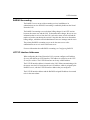
Framed Routes
The Nortel Networks L2TP implementation supports framed routes. With
framed-route support, the LNS does not need to use RIP to learn all routes on a
remote network. Instead, when a user dials in, the RADIUS server sends the LNS
a framed route, which includes all the information that the LNS needs to
communicate with the remote user.
Note: You can configure the LNS to use framed routes for some remote sites
and RIP for other remote sites.
For example, in Figure 1-6, remote site A has three networks, with addresses
1.1.1.0, 1.1.2.0, and 1.1.3.0. Without framed-route support, the LNS uses RIP to
learn the addresses of all three networks, even though all users requiring VPN
services reside only on network 1.1.1.0. The LNS stores the addresses of all three
networks in its routing table. In large network configurations, learning the
addresses of all networks on a remote site can result in many unnecessary routes
in the LNS’s routing table.
L2TP interface
192.3.3.1
1.1.1.0
Users requiring
VPN services
LAC
2.2.2.2
Internet
L2TP tunnel
1.1.2.0
LNS
RADIUS
server
1.1.3.0
Remote
site A
Routing table without
framed route support
1.1.1.0
1.1.2.0
1.1.3.0
L2T0012A
Figure 1-6.
L2TP Network Without Framed-Route Support
308634-14.00 Rev 00
1-17
Configuring L2TP Services
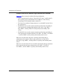
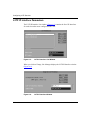
Figure 1-7 shows the same network with framed-route support on the LNS. In this
configuration, remote site A has an associated framed route stored on the central
RADIUS server. This framed route describes the routing table entries required for
the LNS to communicate with users at remote site A.
When a user dials in from remote site A, the RADIUS server sends the framed
route to the LNS as part of the session/user authentication process. The LNS adds
the information contained in the framed route to its routing table. When the
session goes down or the user hangs up, the LNS removes the routes it learned
from the RADIUS server from its routing table.
L2TP interface
192.3.3.1
1.1.1.0
Users requiring
VPN services
LAC
2.2.2.2
Internet
L2TP tunnel
1.1.2.0
LNS
RADIUS
server
1.1.3.0
Remote
site A
Routing table with
framed route support
1.1.1.0
L2T0013A
Figure 1-7.
L2TP Network with Framed-Route Support
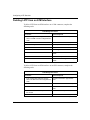
Configuring the Framed-Route Feature
To use the framed-route feature, configure your network as follows:
•
Disable RIP on the remote network for which you want to use framed routes.
For example, in Figure 1-7, you would disable RIP on interface 2.2.2.2.
•
On the RADIUS server, enter the framed route for the remote network. The
framed route is a standard RADIUS attribute, with the following format:
<destination_address>[/<prefix_length>] <gateway> <metric>
destination_address is the address of the remote user’s network.
1-18
308634-14.00 Rev 00
L2TP Overview
prefix_length is optional. It specifies the length of the network mask for the
remote user’s network: 8 for Class A addresses; 16 for Class B addresses; 24
for Class C addresses.
gateway is the address of the interface through which the LNS connects to the
remote user’s network. If you specify 0.0.0.0 for gateway, the system
automatically sets the gateway to the address of the L2TP interface.
metric is the number of hops from the gateway to the destination network.
For example, you would enter the following framed route on the RADIUS
server in Figure 1-7:
1.1.1.0/8 0.0.0.0 1
When the RADIUS server passes this framed route to the LNS, the LNS has
the information it needs to communicate with users on the 1.1.1.0 network.
Name Server Addresses
Nortel Networks implements RFC 1877, “IP Control Protocol (IPCP) Name
Server Addresses,” for L2TP connections. The name server address (NSA) feature
enables a remote host dialing in to a Nortel Networks router acting as an LNS to
obtain NSAs from either the LNS or a RADIUS server.
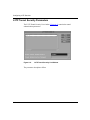
To use the NSA feature, users at remote sites must configure their dial-up
connections in Windows® 95, Windows 98, or Windows NT® to use
server-assigned name server addresses. Users specify this information in the
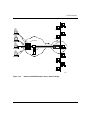
Dial-Up Networking TCP/IP Settings window for the connection (Figure 1-8).
If a user does not select the server-assigned name server addresses setting, the
connection uses the NSAs that the user enters in the TCP/IP Settings window.
308634-14.00 Rev 00
1-19
Configuring L2TP Services
Figure 1-8.
TCP/IP Settings Window for Server-Assigned NSAs
To use server-assigned NSAs, users should not enter primary and secondary
domain name server (DNS) and WINS name server addresses (also called
NetBIOS name server addresses or NBNS addresses).
Instead, when a user dials in, the LNS or the RADIUS server automatically
assigns name server addresses for the connection. If a name server address
changes, the network administrator can make a single modification at the LNS or
RADIUS server site; remote users do not need to go back into the TCP/IP Settings
window to enter a new address.
1-20
308634-14.00 Rev 00
L2TP Overview
Configuring the NSA Feature on the LNS
By default, the NSA feature is disabled on the router acting as the LNS. When
users dial in from a remote location, the connection uses the DNS and NBNS
(WINS) addresses in the Dial-Up Networking TCP/IP Settings window on their
PCs. (See Figure 1-8 on page 1-20.)
To configure the NSA feature on the router, you use Site Manager to set the Name
Server Address Origin parameter to either Local or RADIUS. The following
sections describe these options. (For complete instructions on configuring the
NSA feature on the router, see “Configuring the Name Server Address Feature”
on page 3-9.)
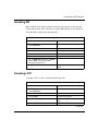
Local
If you set the Name Server Address Origin parameter to Local, users who dial in
to the LNS configured on this slot use the DNS and NetBIOS NSAs that you set in
Site Manager. You set these addresses using the Site Manager parameters Primary
DNS Address, Secondary DNS Address, Primary NBNS Address, and Secondary
NBNS Address.
RADIUS
If you set the Name Server Address Origin parameter to RADIUS, users who dial
in to the LNS on this slot obtain NSAs from a RADIUS server. Using the
RADIUS server, you can specify that certain users use particular NSAs and other
users use other NSAs, even if all users dial in through the same LNS.
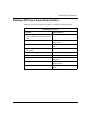
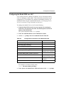
To use a RADIUS server as the name server address origin, your configuration
must meet the following requirements:
•
308634-14.00 Rev 00
The RADIUS server must have entries in its database corresponding to the
incoming host user names.
1-21
Configuring L2TP Services
•
The RADIUS server must support vendor-specific attributes (VSAs) and must
have the following entries in its dictionary:
ATTRIBUTE Bay-Primary-DNS-Server
Bay-VSA(54, ipaddr)
ATTRIBUTE Bay-Secondary-DNS-Server
Bay-VSA(55, ipaddr)
ATTRIBUTE Bay-Primary-NBNS-Server
Bay-VSA(56, ipaddr)
ATTRIBUTE Bay-Secondary-NBNS-Server
Bay-VSA(57, ipaddr)
Example: Name Server Address Origin Parameter Set to Local
Figure 1-9 shows a network with the following configuration:
•
Users at remote hosts A, B, and C have specified “Server assigned name
server addresses” in the Dial-Up Networking TCP/IP Settings window on
their PCs.
•
The Name Server Address Origin parameter is set to Local on the LNS at the
corporate site.
•
The other Site Manager parameters related to this NSA configuration on the
LNS (Primary DNS Address, Secondary DNS Address, Primary NBNS
Address, and Secondary NBNS Address) are set to the addresses of name
servers on the corporate network (DNS 1, DNS 2, NBNS 1, and NBNS 2).
When users at remote hosts A, B, and C make dial-up connections to the corporate
network, those connections use DNS 1, DNS 2, NBNS 1, and NBNS 2 as primary
and secondary name servers.
1-22
308634-14.00 Rev 00
L2TP Overview
DNS 1
Remote
host A
PC
DNS 2
ISP network
Remote
host B
Corporate
network
LNS
LAC
PC
NBNS 1
Remote
host C
PC
TMS
NBNS 2
L2T0010A
Figure 1-9.
Network with Local Name Server Address Origin
308634-14.00 Rev 00
1-23
Configuring L2TP Services
Example: Name Server Address Origin Parameter Set to RADIUS
Figure 1-10 shows a network with the following configuration:
•
Users at remote hosts Eng. host A, Eng. host B, Fin. host C, and Fin. host D
have specified “Server assigned name server addresses” in the Dial-Up
Networking TCP/IP Settings window on their PCs.
•
The Name Server Address Origin parameter is set to RADIUS on the LNS at
the corporate site.
•
The RADIUS server on the corporate network specifies that users dialing in
from remote hosts in Engineering should use Eng. DNS 1, Eng. DNS 2,
Eng. NBNS 1, and Eng. NBNS 2 as their primary and secondary name
servers.
•
The RADIUS server on the corporate network specifies that users dialing in
from remote hosts in Finance should use Fin. DNS 1, Fin. DNS 2, Fin. NBNS
1, and Fin. NBNS 2 as their primary and secondary name servers.
When users at remote hosts Eng. host A and Eng. host B make dial-up
connections to the corporate network, those connections use Eng. DNS 1,
Eng. DNS 2, Eng. NBNS 1, and Eng. NBNS 2 as primary and secondary name
servers.
When users at remote hosts Fin. host A and Fin. host B make dial-up connections
to the corporate network, those connections use Fin. DNS 1, Fin. DNS 2,
Fin. NBNS 1, and Fin. NBNS 2 as primary and secondary name servers.
1-24
308634-14.00 Rev 00
L2TP Overview
Eng. DNS 1
Eng.
host A
Eng. DNS 2
PC
Eng.
host B
Eng. NBNS 1
PC
Eng. NBNS 2
ISP network
Corporate
network
LNS
LAC
Fin.
host A
PC
RADIUS
server
Fin.
host B
PC
TMS
Fin. DNS 1
Fin. DNS 2
Fin. NBNS 1
Fin.NBNS 2
L2T0011A
Figure 1-10.
Network with RADIUS Name Server Address Origin
308634-14.00 Rev 00
1-25
Configuring L2TP Services
Checking NSA Assignments from the Remote Host
To see which NSAs the LNS or RADIUS server assigned to a particular user,
complete the following steps at the remote user’s PC:
1.
Choose Start > Run.
The Run window opens (Figure 1-11).
Figure 1-11.
2.
Run Window
At the Open: prompt, enter:
winipcfg
The IP Configuration window opens (Figure 1-12).
1-26
308634-14.00 Rev 00
L2TP Overview
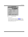
Figure 1-12.
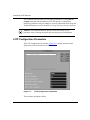
3.
IP Configuration Window
Click on More Info.
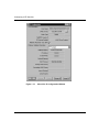
The More Info. IP Configuration window opens (Figure 1-13). The DNS
Servers field lists the primary and secondary DNS server addresses assigned
by the server. (Click on the ... button to see the secondary server address.)
The Primary WINS Server and Secondary WINS Server fields list the primary
and secondary NBNS addresses, if any.
308634-14.00 Rev 00
1-27
Configuring L2TP Services
Figure 1-13.
1-28
More Info. IP Configuration Window
308634-14.00 Rev 00
L2TP Overview
Where to Go Next
Go to one of the following chapters for more information:
If you want to
Go to
Start L2TP on a router using default parameter settings.
Chapter 2
Change default settings for L2TP parameters.
Chapter 3
Obtain information about Site Manager parameters (this is the same
information that you obtain using Site Manager online Help).
Appendix A
Review configuration examples.
Appendix B
Troubleshoot L2TP configuration problems.
Appendix C
308634-14.00 Rev 00
1-29
Chapter 2
Starting L2TP
The quickest way to start L2TP is to enable it with the default configuration that
Nortel Networks software supplies. This configuration uses all available
parameter defaults. You need to supply values for several parameters that do not
have default values.
This chapter includes the following information:
Topic
Page
Planning Considerations for an L2TP Network
2-2
Preparing a Configuration File
2-3
Enabling L2TP on an Unconfigured WAN Interface
2-4
Enabling L2TP on an Existing PPP Interface
2-5
Enabling L2TP on an Existing Frame Relay Interface
2-7
Enabling L2TP on an Existing ATM Interface
2-9
308634-14.00 Rev 00
2-1
Configuring L2TP Services
Planning Considerations for an L2TP Network
This guide primarily explains how to configure a Nortel Networks AN, ARN,
BLN, BCN, or ASN router as an LNS in an L2TP network. To successfully
operate in an L2TP network, obtain the following information to configure the
LNS.
Tunnel Authentication Passwords
If you plan to enable tunnel authentication, which is optional for the Nortel
Networks LNS, you must obtain the LAC password from your ISP. For more
information about the authentication process, see “Tunnel Authentication” on
page 1-12.
RADIUS Server Information
The Nortel Networks implementation of L2TP requires that you configure a
RADIUS server to perform user authentication and to assign IP addresses to
remote users.
For the RADIUS server, do the following:
•
Configure the RADIUS server with user names and domain names.
•
Obtain the address and password of the RADIUS server to enter in the LNS
configuration.
•
Configure the RADIUS server to assign IP addresses to remote users.
This address identifies the remote user to the LNS during an L2TP session. If
the remote user does not have a preconfigured address, the only way to assign
addresses is by the RADIUS server. This address is also used for network
communication across the subscriber network.
For more information about configuring Nortel Networks routers as RADIUS
clients, see Configuring RADIUS.
2-2
308634-14.00 Rev 00
Starting L2TP
Preparing a Configuration File
Before starting L2TP, you must create and save a configuration file with at least
one WAN interface, for example, a synchronous or MCT1 port.
Note: L2TP is not compatible with dial services. Do not enable L2TP on the
same slot that you enable for a dial service, such as dial-on-demand, dial
backup, or bandwidth-on-demand.
For information about the Site Manager configuration tool and how to work with
configuration files, see Configuring and Managing Routers with Site Manager.
To open the configuration file, complete the following tasks:
Site Manager Procedure
You do this
System responds
1. In the main Site Manager window, choose The Tools menu opens.
Tools.
2. Choose Configuration Manager.
The Configuration Manager menu opens.
3. Choose Local File, Remote File,
Dynamic, or Cache.
Site Manager prompts you for the
configuration file that you want to open.
4. Select the file and click on OK.
The Configuration Manager window
opens, displaying the router modules.
From the Configuration Manager window, go to one of the following sections to
enable L2TP:
Section
Page
Enabling L2TP on an Unconfigured WAN Interface
2-4
Enabling L2TP on an Existing PPP Interface
2-5
Enabling L2TP on an Existing Frame Relay Interface
2-7
Enabling L2TP on an Existing ATM Interface
2-9
308634-14.00 Rev 00
2-3
Configuring L2TP Services
Enabling L2TP on an Unconfigured WAN Interface
To enable L2TP on an unconfigured WAN interface, complete the following tasks:
Site Manager Procedure
You do this
System responds
1. In the Configuration Manager window,
click on a WAN connector.
The Add Circuit window opens.
2. Accept the default circuit name or change
it, then click on OK.
The WAN Protocols window opens.
3. Choose PPP, Frame Relay, or ATM DXI,
then click on OK.
The Select Protocols window opens.
(To configure ATM on an ATM interface, see
Configuring ATM Services, then go to
“Enabling L2TP on an Existing ATM Interface”
on page 2-9.)
4. Choose L2TP, then click on OK.
The IP Configuration window opens.
5. Enter the IP address of the LNS (router),
then click on OK.
The L2TP Configuration window opens.
6. Set the following parameters:
• RADIUS Primary Server IP Address
• RADIUS Primary Server Password
• RADIUS Client IP Address
Click on Help or see the parameter
descriptions beginning on page A-5.
7. Click on OK.
The L2TP Tunneling Security window
opens.
8. Click on OK.
The L2TP IP Interface List window opens,
followed by the L2TP IP Interface
Configuration window.
9. Set the following parameters:
• L2TP IP Interface Address
• Subnet Mask
Click on Help or see the parameter
descriptions beginning on page A-13.
(continued)
2-4
308634-14.00 Rev 00
Starting L2TP
Site Manager Procedure (continued)
You do this
System responds
10. Click on OK.
Site Manager displays a message
alerting you of the time delay to create
the L2TP tunnel circuits.
11. Click on OK.
You return to the L2TP IP Interface List
window, which displays the IP interface
address and the subnet mask. A
message window opens that reads, L2TP
Configuration is completed.
12. Click on Done.
You return to the Configuration Manager
window.
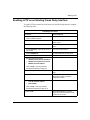
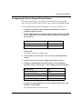
Enabling L2TP on an Existing PPP Interface
To enable L2TP on an interface with PPP and IP already enabled, complete the
following tasks:
Site Manager Procedure
You do this
System responds
1. In the Configuration Manager window,
click on a WAN connector.
The Edit Connector window opens.
2. Choose Edit Circuit.
The Circuit Definition window opens.
3. Choose Protocols in the top left corner of The Protocols menu opens.
the window.
4. Choose Add/Delete.
The Select Protocols window opens.
5. Choose L2TP, then click on OK.
The L2TP Configuration window opens.
6. Set the following parameters:
• RADIUS Primary Server IP Address
• RADIUS Primary Server Password
• RADIUS Client IP Address
Click on Help or see the parameter
descriptions beginning on page A-5.
7. Click on OK.
The L2TP Tunneling Security window
opens.
(continued)
308634-14.00 Rev 00
2-5
Configuring L2TP Services
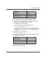
Site Manager Procedure (continued)
You do this
System responds
8. Click on OK.
The L2TP IP Interface List window opens,
followed by the L2TP IP Interface
Configuration window.
9. Set the following parameters:
• L2TP IP Interface Address
• Subnet Mask
Click on Help or see the parameter
descriptions beginning on page A-13.
2-6
10. Click on OK.
Site Manager displays a message
alerting you of the time delay to create
the L2TP tunnel circuits.
11. Click on OK.
You return to the L2TP IP Interface List
window, which displays the IP interface
address and the subnet mask. A
message window opens that reads, L2TP
Configuration is completed.
12. Click on Done.
You return to the Circuit Definition
window.
13. Choose File.
The File menu opens.
14. Choose Exit.
You return to the Configuration Manager
window.
308634-14.00 Rev 00
Starting L2TP
Enabling L2TP on an Existing Frame Relay Interface
To enable L2TP on an interface with frame relay and IP already enabled, complete
the following tasks:
Site Manager Procedure
You do this
System responds
1. In the Configuration Manager window,
click on a WAN connector.
The Edit Connector window opens.
2. Choose Edit Circuit.
The Frame Relay Circuit Definition
window opens.
3. Choose Services.
The Frame Relay Service List window
opens.
4. Choose Protocols in the top left corner of The Protocols menu opens.
the window.
5. Choose Add/Delete.
The Select Protocols window opens.
6. Choose L2TP, then click on OK.
The L2TP Configuration window opens.
7. Set the following parameters:
• RADIUS Primary Server IP Address
• RADIUS Primary Server Password
• RADIUS Client IP Address
Click on Help or see the parameter
descriptions beginning on page A-5.
8. Click on OK.
The L2TP Tunneling Security window
opens.
9. Click on OK.
The L2TP IP Interface List window opens,
followed by the L2TP IP Interface
Configuration window.
10. Set the following parameters:
• L2TP IP Interface Address
• Subnet Mask
Click on Help or see the parameter
descriptions beginning on page A-13.
11. Click on OK.
Site Manager displays a message
alerting you of the time delay to create
the L2TP tunnel circuits.
(continued)
308634-14.00 Rev 00
2-7
Configuring L2TP Services
Site Manager Procedure (continued)
2-8
You do this
System responds
12. Click on OK.
You return to the L2TP IP Interface List
window, which displays the IP interface
address and the subnet mask. A
message window opens that reads, L2TP
Configuration is completed.
13. Click on Done.
You return to the Frame Relay Service
List window.
14. Click on Done.
You return to the Frame Relay Circuit
Definition window.
15. Click on Done.
You return to the Configuration Manager
window.
308634-14.00 Rev 00
Starting L2TP
Enabling L2TP on an Existing ATM Interface
To enable L2TP on an interface with ATM and IP already enabled, you enable
L2TP in one of two ways. If your interface uses a COM connector, complete the
tasks in the following table. If your interface uses an ATM connector, go to
page 2-10.
Site Manager Procedure
You do this
System responds
1. In the Configuration Manager window,
click on a WAN connector.
The Edit Connector window opens.
2. Choose Edit Circuit.
The Circuit Definition window opens.
3. Choose Group Protocols.
The Group Protocols menu opens.
4. Choose Add/Delete.
The Select Protocols window opens.
5. Choose L2TP, then click on OK.
The L2TP Configuration window opens.
6. Set the following parameters:
• RADIUS Primary Server IP Address
• RADIUS Primary Server Password
• RADIUS Client IP Address
Click on Help or see the parameter
descriptions beginning on page A-5.
7. Click on OK.
The L2TP Tunneling Security window
opens.
8. Click on OK.
The L2TP IP Interface List window opens,
followed by the L2TP IP Interface
Configuration window.
9. Set the following parameters:
• L2TP IP Interface Address
• Subnet Mask
Click on Help or see the parameter
descriptions beginning on page A-13.
10. Click on OK.
Site Manager displays a message
alerting you of the time delay to create
the L2TP tunnel circuits.
(continued)
308634-14.00 Rev 00
2-9
Configuring L2TP Services
Site Manager Procedure (continued)
You do this
System responds
11. Click on OK.
You return to the L2TP IP Interface List
window, which displays the IP interface
address and the subnet mask. A
message window opens that reads, L2TP
Configuration is completed.
12. Click on Done.
You return to the Circuit Definition
window.
13. Choose File.
The File menu opens.
14. Choose Exit.
You return to the Configuration Manager
window.
If your ATM interface uses an ATM connector, complete the following tasks:
Site Manager Procedure
2-10
You do this
System responds
1. In the Configuration Manager window,
click on an ATM connector.
The Select Connection Type window
opens.
2. Click on ATM.
The Edit ATM Connector window opens.
3. Choose Service Attributes.
The ATM Service Records List window
opens.
4. Choose Protocols.
The Protocols menu opens.
5. Choose Add/Delete.
The Select Protocols window opens.
6. Choose L2TP, then click on OK.
The L2TP Configuration window opens.
7. Complete steps 6 through 11 in the
previous table.
Site Manager enables L2TP.
8. Click on Done.
You return to the ATM Service Records
List window.
9. Click on Done.
You return to the Edit ATM Connector
window.
10. Click on Done.
You return to the Select Connection Type
window.
11. Click on Done.
You return to the Configuration Manager
window.
308634-14.00 Rev 00
Chapter 3
Customizing L2TP Services
When you enable L2TP, default values are in effect for most parameters (see
parameter descriptions in Appendix A, “L2TP Parameters”). You may want to
change some of these values, depending on the requirements of your network.
This chapter includes the following information:
Topic
Page
Modifying the L2TP Protocol Configuration
3-2
Modifying RADIUS Server Information
3-3
Changing the LNS System Name
3-4
Modifying the Number of L2TP Sessions Permitted
3-5
Keeping the Remote User’s Domain Name
3-6
Changing the Domain Name Delimiter
3-7
Enabling Tunnel Authentication
3-8
Configuring the Name Server Address Feature
3-9
Modifying L2TP IP Interface Addresses
3-10
Disabling RIP
3-11
Disabling L2TP
3-11
Deleting L2TP from a PPP Interface
3-12
Deleting L2TP from a Frame Relay Interface
3-13
Deleting L2TP from an ATM Interface
3-14
308634-14.00 Rev 00
3-1
Configuring L2TP Services
Modifying the L2TP Protocol Configuration
To modify how data is transmitted across an L2TP network, such as the number,
frequency, and timing of data and acknowledgment packets exchanged between
the LNS and the LAC, you can modify the L2TP protocol parameters.
To modify the L2TP protocol configuration, complete the following tasks:
Site Manager Procedure
You do this
System responds
1. In the Configuration Manager window,
choose Protocols.
The Protocols menu opens.
2. Choose IP.
The IP menu opens.
3. Choose L2TP.
The L2TP menu opens.
4. Choose L2TP Configuration.
The L2TP Configuration List window
opens.
5. Select an LNS entry from the list.
6. Edit any of the following parameters:
• Receive Window Size
• Retransmit Timer (seconds)
• Maximum Retransmit
• Hello Timer (seconds)
• Ack Timeout (milliseconds)
• Congestion Control
Click on Help or see the parameter
descriptions beginning on page A-3.
7. Click on Done.
3-2
You return to the Configuration Manager
window.
308634-14.00 Rev 00
Customizing L2TP Services
Modifying RADIUS Server Information
If you change the address of the RADIUS server that you are using to authenticate
remote users and manage accounting functions, you must update the server
address information on the LNS.
For more information about using a RADIUS server in an L2TP network, see
“RADIUS Server” on page 1-6.
To modify the address of the RADIUS server, complete the following tasks:
Site Manager Procedure
You do this
System responds
1. In the Configuration Manager window,
choose Protocols.
The Protocols menu opens.
2. Choose IP.
The IP menu opens.
3. Choose L2TP.
The L2TP menu opens.
4. Choose L2TP Configuration.
The L2TP Configuration List window
opens.
5. Select an LNS entry from the list.
6. Set the following parameters:
• RADIUS Primary Server IP Address
• RADIUS Primary Server Password
• RADIUS Client IP Address
Click on Help or see the parameter
descriptions beginning on page A-5.
7. Click on Done.
You return to the Configuration Manager
window.
You can also modify the RADIUS information in the configuration windows
specific to RADIUS. For more information, see Configuring RADIUS.
308634-14.00 Rev 00
3-3
Configuring L2TP Services
Changing the LNS System Name
The LNS system name is the name of the router. This name is used during tunnel
setup to identify the LNS uniquely.
By default, Site Manager enters the system name that you initially configured
when first accessing the router. See Configuring and Managing Routers with Site
Manager for more details about system information.
To change the LNS system name, complete the following tasks:
Site Manager Procedure
You do this
System responds
1. In the Configuration Manager window,
choose Protocols.
The Protocols menu opens.
2. Choose IP.
The IP menu opens.
3. Choose L2TP.
The L2TP menu opens.
4. Choose L2TP Configuration.
The L2TP Configuration List window
opens.
5. Select an LNS entry from the list.
6. Set the LNS System Name parameter.
Click on Help or see the parameter
description on page A-5.
7. Click on Done.
3-4
You return to the Configuration Manager
window.
308634-14.00 Rev 00
Customizing L2TP Services
Modifying the Number of L2TP Sessions Permitted
You can modify the maximum number of active L2TP sessions that the LNS can
manage. The default is 100 sessions for all routers except the AN. (The default
number of sessions for the AN is 50.)
For more information about L2TP sessions, see “L2TP Sessions” on page 1-3.
To change the maximum number of L2TP sessions supported by the LNS,
complete the following tasks:
Site Manager Procedure
You do this
System responds
1. In the Configuration Manager window,
choose Protocols.
The Protocols menu opens.
2. Choose IP.
The IP menu opens.
3. Choose L2TP.
The L2TP menu opens.
4. Choose L2TP Configuration.
The L2TP Configuration List window
opens.
5. Select an LNS entry from the list.
6. Set the Max L2TP Sessions parameter.
Click on Help or see the parameter
description on page A-3.
7. Click on Done.
308634-14.00 Rev 00
You return to the Configuration Manager
window.
3-5
Configuring L2TP Services
Keeping the Remote User’s Domain Name
By default, the LNS removes the domain name from the complete user name
before passing it on to the RADIUS server for user authentication.
To keep the domain name with the user name, complete the following tasks:
Site Manager Procedure
You do this
System responds
1. In the Configuration Manager window,
choose Protocols.
The Protocols menu opens.
2. Choose IP.
The IP menu opens.
3. Choose L2TP.
The L2TP menu opens.
4. Choose L2TP Configuration.
The L2TP Configuration List window
opens.
5. Select an LNS entry from the list.
6. Set the Remove Domain Name
parameter to Disable. Click on Help or
see the parameter description on
page A-7.
7. Click on Done.
3-6
You return to the Configuration Manager
window.
308634-14.00 Rev 00
Customizing L2TP Services
Changing the Domain Name Delimiter
In the complete user name, a single-character delimiter separates the user name
from the domain name. By default, the LNS removes the domain name when it
receives a call. The delimiter tells the LNS which characters to remove. The
default delimiter is an at sign (@).
To change the delimiter, complete the following tasks:
Site Manager Procedure
You do this
System responds
1. In the Configuration Manager window,
choose Protocols.
The Protocols menu opens.
2. Choose IP.
The IP menu opens.
3. Choose L2TP.
The L2TP menu opens.
4. Choose L2TP Configuration.
The L2TP Configuration List window
opens.
5. Select an LNS entry from the list.
6. Set the Domain Name Delimiter
parameter. Click on Help or see the
parameter description on page A-7.
7. Click on Done.
308634-14.00 Rev 00
You return to the Configuration Manager
window.
3-7
Configuring L2TP Services
Enabling Tunnel Authentication
To prevent unauthorized users from accessing the corporate network, you can
enable tunnel authentication. During tunnel negotiation, the LAC sends its tunnel
authentication password to the LNS. If the password is not recognized by the
LNS, authentication is unsuccessful and the LAC cannot create the tunnel.
Note: If you are using the Password Authentication Protocol (PAP) for PPP
authentication, do not enable tunnel authentication.
For more information about tunnel authentication, see “Tunnel Authentication” on
page 1-12.
To enable tunnel authentication, complete the following tasks:
Site Manager Procedure
You do this
System responds
1. In the Configuration Manager window,
choose Protocols.
The Protocols menu opens.
2. Choose IP.
The IP menu opens.
3. Choose L2TP.
The L2TP menu opens.
4. Choose Tunnel Authentication.
The L2TP Tunnel Security List window
opens.
5. Select an LNS entry from the list.
6. Set the following parameters:
• Enable Tunnel Authentication
• Tunnel Authentication Password
Click on Help or see the parameter
descriptions on page A-11.
7. Click on Done.
3-8
You return to the Configuration Manager
window.
308634-14.00 Rev 00
Customizing L2TP Services
Configuring the Name Server Address Feature
The name server address (NSA) feature enables a remote host dialing in to a
Nortel Networks router acting as an LNS to obtain NSAs from either the LNS or a
RADIUS server. For more information about the name server address feature and
how to configure the remote host to use NSAs, see “Name Server Addresses” on
page 1-19.
To configure the NSA feature on the LNS, complete the following tasks:
Site Manager Procedure
You do this
System responds
1. In the Configuration Manager window,
choose Protocols.
The Protocols menu opens.
2. Choose IP.
The IP menu opens.
3. Choose L2TP.
The L2TP menu opens.
4. Choose L2TP Configuration.
The L2TP Configuration List window
opens.
5. Select an LNS entry from the list.
6. Set the Name Server Address Origin
parameter. Click on Help or see the
parameter description on page A-8.
7. If you set the Name Server Address
Origin parameter to Local, set the
following parameters:
•
•
•
•
Primary DNS Address
Secondary DNS Address
Primary NBNS Address
Secondary NBNS Address
Click on Help or see the parameter
descriptions beginning on page A-8.
8. Click on Done.
308634-14.00 Rev 00
You return to the Configuration Manager
window.
3-9
Configuring L2TP Services
Modifying L2TP IP Interface Addresses
The L2TP IP Interface List window lists the L2TP IP interface addresses for each
slot that has L2TP configured. The LNS uses the addresses internally to identify
the remote sites.
For more information about the L2TP IP interface, see “L2TP IP Interface
Addresses” on page 1-15.
To change an address in the list, complete the following tasks:
Site Manager Procedure
You do this
System responds
1. In the Configuration Manager window,
choose Protocols.
The Protocols menu opens.
2. Choose IP.
The IP menu opens.
3. Choose L2TP.
The L2TP menu opens.
4. Choose L2TP IP Interface.
The L2TP IP Interface List window opens.
5. Select an LNS entry from the list.
6. Click on Change.
The L2TP IP Interface window opens.
7. Modify the following parameters:
• L2TP IP Interface Address
• Subnet Mask
Click on Help or see the parameter
descriptions beginning on page A-13.
3-10
8. Click on OK.
You return to the L2TP IP Interface List
window. The new address appears in the
list.
9. Click on Done.
You return to the Configuration Manager
window.
308634-14.00 Rev 00
Customizing L2TP Services
Disabling RIP
RIP is enabled on the LNS by default so that the LNS can learn routes from the
remote dial-in router. If the LNS does not require RIP support, you can disable it.
To disable RIP, complete the following tasks:
Site Manager Procedure
You do this
System responds
1. In the Configuration Manager window,
choose Protocols.
The Protocols menu opens.
2. Choose IP.
The IP menu opens.
3. Choose L2TP.
The L2TP menu opens.
4. Choose L2TP IP Interface.
The L2TP IP Interface List window opens.
5. Select an LNS entry from the list.
6. Set the RIP Enable parameter to Disable.
Click on Help or see the parameter
description on page A-14.
7. Click on Done.
You return to the Configuration Manager
window.
Disabling L2TP
To disable L2TP on a slot, complete the following tasks:
Site Manager Procedure
You do this
System responds
1. In the Configuration Manager window,
choose Protocols.
The Protocols menu opens.
2. Choose IP.
The IP menu opens.
3. Choose L2TP.
The L2TP menu opens.
4. Choose L2TP Configuration.
The L2TP Configuration List window
opens.
5. Select an LNS entry from the list.
(continued)
308634-14.00 Rev 00
3-11
Configuring L2TP Services
Site Manager Procedure (continued)
You do this
System responds
6. Set the Enable L2TP parameter to
Disable. Click on Help or see the
parameter description on page A-3.
Site Manager disables L2TP for the slot.
7. Click on Done.
You return to the Configuration Manager
window.
Deleting L2TP from a PPP Interface
To delete L2TP from a PPP interface, complete the following tasks:
Site Manager Procedure
3-12
You do this
System responds
1. In the Configuration Manager window,
click on a WAN connector configured with
L2TP.
The Edit Connector window opens.
2. Choose Edit Circuit.
The Circuit Definition window opens.
3. Choose Protocols.
The Protocols menu opens.
4. Choose Add/Delete.
The Select Protocols window opens.
5. Click on L2TP.
Site Manager deselects L2TP.
6. Click on OK.
You return to the Circuit Definition
window.
7. Choose File.
The File menu opens.
8. Choose Exit.
You return to the Configuration Manager
window.
308634-14.00 Rev 00
Customizing L2TP Services
Deleting L2TP from a Frame Relay Interface
To delete L2TP from a frame relay interface, complete the following tasks:
Site Manager Procedure
You do this
System responds
1. In the Configuration Manager window,
click on a WAN connector configured with
L2TP.
The Edit Connector window opens.
2. Choose Edit Circuit.
The Frame Relay Circuit Definition
window opens.
3. Choose Services.
The Frame Relay Service List window
opens.
4. Choose Protocols in the top left corner of The Protocols menu opens.
the window.
5. Choose Add/Delete.
The Select Protocols window opens.
6. Click on L2TP.
Site Manager deselects L2TP.
7. Click on OK.
You return to the Frame Relay Service
List window.
8. Click on Done.
You return to the Frame Relay Circuit
Definition window.
9. Click on Done.
You return to the Configuration Manager
window.
308634-14.00 Rev 00
3-13
Configuring L2TP Services
Deleting L2TP from an ATM Interface
To delete L2TP from an ATM interface on a COM connector, complete the
following tasks:
Site Manager Procedure
You do this
System responds
1. In the Configuration Manager window,
click on a COM connector configured with
L2TP.
The Edit Connector window opens.
2. Choose Edit Circuit.
The Circuit Definition window opens.
3. Choose Group Protocols.
The Group Protocols menu opens.
4. Choose Add/Delete.
The Select Protocols window opens.
5. Click on L2TP.
Site Manager deselects L2TP.
6. Click on OK.
You return to the Circuit Definition
window.
7. Choose File.
The File menu opens.
8. Choose Exit.
You return to the Configuration Manager
window.
To delete L2TP from an ATM interface on an ATM connector, complete the
following tasks:
Site Manager Procedure
You do this
System responds
1. In the Configuration Manager window,
The Select Connection Type window
click on an ATM connector configured with opens.
L2TP.
2. Click on ATM.
The Edit ATM Connector window opens.
3. Choose Service Attributes.
The ATM Service Records List window
opens.
4. Choose Protocols in the top left corner of The Protocols menu opens.
the window.
5. Choose Add/Delete.
The Select Protocols window opens.
(continued)
3-14
308634-14.00 Rev 00
Customizing L2TP Services
Site Manager Procedure (continued)
You do this
System responds
6. Click on L2TP.
Site Manager deselects L2TP.
7. Click on OK.
You return to the ATM Service Records
List window.
8. Click on Done.
You return to the Edit ATM Connector
window.
9. Click on Done.
Your return to the Select Connection Type
window.
10. Click on Done.
You return to the Configuration Manager
window.
308634-14.00 Rev 00
3-15
Appendix A
L2TP Parameters
This appendix contains the Site Manager parameter descriptions for L2TP
services. You can display the same information using Site Manager online Help.
For information about the IP parameters that you set when enabling L2TP, see
Configuring IP, ARP, RARP, RIP, and OSPF Services.
This appendix contains the following information:
Topic
Page
L2TP Configuration Parameters
A-2
L2TP Tunnel Security Parameters
A-10
L2TP IP Interface Parameters
A-12
For each parameter, this appendix provides the following information:
•
Parameter name
•
Configuration Manager menu path
•
Default setting
•
Valid parameter options
•
Parameter function
•
Instructions for setting the parameter
•
Management information base (MIB) object ID
308634-14.00 Rev 00
A-1
Configuring L2TP Services
The Technician Interface allows you to modify parameters by issuing set and
commit commands with the MIB object ID. This process is equivalent to
modifying parameters using Site Manager. For more information about using the
Technician Interface to access the MIB, see Using Technician Interface Software.
Caution: The Technician Interface does not verify the validity of your
parameter values. Entering an invalid value can corrupt your configuration.
L2TP Configuration Parameters
The L2TP Configuration List window (Figure A-1) contains parameters that
define how L2TP sends and receives data.
Figure A-1.
L2TP Configuration List Window
The parameter descriptions follow.
A-2
308634-14.00 Rev 00
L2TP Parameters
Parameter: Enable L2TP
Path:
Default:
Options:
Function:
Instructions:
Configuration Manager > Protocols > IP > L2TP > L2TP Configuration
Enable
Enable | Disable
Enables or disables L2TP on this interface.
Site Manager automatically sets this parameter to Enable when you select L2TP
as a protocol. Accept the default, Enable, to use L2TP. To temporarily disable
L2TP, set this parameter to Disable.
MIB Object ID: 1.3.6.1.4.1.18.3.5.23.2.1.2
Parameter: Max L2TP Sessions
Path:
Default:
Options:
Function:
Instructions:
MIB Object ID:
Configuration Manager > Protocols > IP > L2TP > L2TP Configuration
100 (50 for the AN router)
1 to 150 sessions (1 to 75 sessions for AN)
Specifies the maximum number of L2TP sessions that the LNS allows.
Enter the maximum number of L2TP sessions that you want the LNS to support.
1.3.6.1.4.1.18.3.5.23.2.1.16
Parameter: Receive Window Size
Path:
Default:
Options:
Function:
Configuration Manager > Protocols > IP > L2TP > L2TP Configuration
4
1 to 7 packets
Specifies the number of control packets that the LNS can receive from the LAC
without the LNS sending an acknowledgment packet to the LAC.
Instructions: Enter the number of packets that determine the window size, or accept the
default value.
MIB Object ID: 1.3.6.1.4.1.18.3.5.23.2.1.6
308634-14.00 Rev 00
A-3
Configuring L2TP Services
Parameter: Retransmit Timer (seconds)
Path:
Default:
Options:
Function:
Configuration Manager > Protocols > IP > L2TP > L2TP Configuration
1
1 to 60 seconds
Indicates the number of seconds that the LNS waits for an acknowledgment
from the LAC before resending packets.
Instructions: If you are experiencing many timeouts during L2TP tunnel negotiation or
during a session, set this value to a number greater than the default. Otherwise,
accept the default.
MIB Object ID: 1.3.6.1.4.1.18.3.5.23.2.1.7
Parameter: Maximum Retransmit
Path:
Default:
Options:
Function:
Configuration Manager > Protocols > IP > L2TP > L2TP Configuration
5
1 to 60
Specifies the maximum number of times that the LNS retransmits packets to the
LAC.
Instructions: If you are experiencing many timeouts during L2TP tunnel negotiation or
during a session, set this value to a number greater than the default. Otherwise,
accept the default.
MIB Object ID: 1.3.6.1.4.1.18.3.5.23.2.1.8
Parameter: Hello Timer (seconds)
Path:
Default:
Options:
Function:
Configuration Manager > Protocols > IP > L2TP > L2TP Configuration
60
1 to 60 seconds
Indicates the maximum number of seconds that can elapse without data activity
before the LNS sends a packet through the tunnel to the LAC to check the
connection.
Instructions: Set this parameter to a smaller number only if the connection is not stable.
Otherwise, accept the default.
MIB Object ID: 1.3.6.1.4.1.18.3.5.23.2.1.9
A-4
308634-14.00 Rev 00
L2TP Parameters
Parameter: Ack Timeout (milliseconds)
Path:
Default:
Options:
Function:
Configuration Manager > Protocols > IP > L2TP > L2TP Configuration
250
1 to 360 milliseconds
Specifies the maximum number of milliseconds that can elapse before the LNS
sends an acknowledgment to the LAC that it received an L2TP control message,
such as a tunnel authentication or session control message.
Instructions: If you are unsure of the stability of the connection or the L2TP session, set this
parameter to a number smaller than the default. Otherwise, accept the default.
MIB Object ID: 1.3.6.1.4.1.18.3.5.23.2.1.10
Parameter: LNS System Name
Path:
Default:
Options:
Function:
Configuration Manager > Protocols > IP > L2TP > L2TP Configuration
BayRS
The router’s system name or any name you specify
Specifies the name of the LNS. This name applies to the router, not just to the
slot with the LNS interface.
Instructions: Site Manager automatically enters the name from the router’s system
information. You can modify it, if you choose. If no system name is provided,
the router uses BayRS.
MIB Object ID: 1.3.6.1.4.1.18.3.5.23.2.1.12
Parameter: RADIUS Primary Server IP Address
Path:
Default:
Options:
Function:
Instructions:
Configuration Manager > Protocols > IP > L2TP > L2TP Configuration
None
Any 32-bit IP address
Specifies the primary RADIUS server for user authentication.
Enter the IP address of the RADIUS server. If the RADIUS server is already
configured, Site Manager automatically supplies the address.
MIB Object ID: 1.3.6.1.4.1.18.3.5.22.2.1.3
308634-14.00 Rev 00
A-5
Configuring L2TP Services
Parameter: RADIUS Primary Server Password
Path:
Default:
Options:
Function:
Instructions:
Configuration Manager > Protocols > IP > L2TP > L2TP Configuration
None
Any alphanumeric string, up to a maximum of 64 characters
Specifies the primary RADIUS server’s password.
Enter the password for the RADIUS server. If the RADIUS server is already
configured, Site Manager automatically supplies the password.
MIB Object ID: 1.3.6.1.4.1.18.3.5.22.2.1.11
Parameter: RADIUS Client IP Address
Path:
Default:
Options:
Function:
Instructions:
Configuration Manager > Protocols > IP > L2TP > L2TP Configuration
None
Any IP address
Identifies the router acting as the LNS. This address applies to the entire router.
Enter the IP address of the router. If the RADIUS server is already configured,
Site Manager automatically supplies the address.
MIB Object ID: 1.3.6.1.4.1.18.3.5.22.1.1.5
Parameter: Congestion Control
Path:
Default:
Options:
Function:
Configuration Manager > Protocols > IP > L2TP > L2TP Configuration
Disable
Enable | Disable
Specifies whether the LNS uses flow control on the tunneled data packets. Flow
control ensures the stable flow of data between both sides of the connection.
Instructions: To enable flow control, select Enable. Otherwise, accept the default, Disable.
MIB Object ID: 1.3.6.1.4.1.18.3.5.23.2.1.20
A-6
308634-14.00 Rev 00
L2TP Parameters
Parameter: Remove Domain Name
Path:
Default:
Options:
Function:
Configuration Manager > Protocols > IP > L2TP > L2TP Configuration
Enable
Enable | Disable
Instructs the router whether to remove the domain name from the complete user
name before RADIUS authentication takes place. If enabled, the LNS removes
the delimiter separating the user name and the domain name and all characters
to the right of the delimiter. Removing the domain name ensures that the
RADIUS server can identify the user without having to reconfigure the names in
the server database.
Instructions: Accept the default, Enable, to remove the domain name from the user name.
Select Disable to keep the domain name.
MIB Object ID: 1.3.6.1.4.1.18.3.5.23.2.1.21
Parameter: Domain Name Delimiter
Path:
Default:
Options:
Function:
Configuration Manager > Protocols > IP > L2TP > L2TP Configuration
@
A single-character string (for example, a colon)
This character identifies the delimiter used to separate the domain name from
the user name. This parameter is relevant only if you accept the default value,
Enable, for the Remove Domain Name parameter.
Instructions: Specify a character as a delimiter or accept the default.
MIB Object ID: 1.3.6.1.4.1.18.3.5.23.2.1.22
308634-14.00 Rev 00
A-7
Configuring L2TP Services
Parameter: Name Server Address Origin
Path:
Default:
Options:
Function:
Configuration Manager > Protocols > IP > L2TP > L2TP Configuration
Disable
Disable | Local | RADIUS
Specifies whether or not the NSA feature is enabled and, if enabled, specifies
the source of the domain name server (DNS) and NetBIOS name server (NBNS)
addresses.
Instructions: Set to Disable if you do not want to use the NSA feature. If this feature is
disabled, remote hosts use the DNS and NBNS addresses configured for their
individual dial-up connections. Set to Local if you want all remote hosts to use
the DNS and NBNS addresses that you configure in Site Manager. Set to
RADIUS if you want remote hosts to obtain DNS and NBNS addresses from a
RADIUS server.
MIB Object ID: 1.3.6.1.4.1.18.3.5.23.2.1.23
Parameter: Primary DNS Address
Path:
Default:
Options:
Function:
Configuration Manager > Protocols > IP > L2TP > L2TP Configuration
None
Any valid IP address
If the Name Server Address Origin parameter is set to Local, the Primary DNS
Address parameter specifies the address of the primary domain name server
(DNS) that every remote host should use.
Instructions: Enter the IP address of the primary DNS.
MIB Object ID: 1.3.6.1.4.1.18.3.5.23.2.1.24
A-8
308634-14.00 Rev 00
L2TP Parameters
Parameter: Secondary DNS Address
Path:
Default:
Options:
Function:
Configuration Manager > Protocols > IP > L2TP > L2TP Configuration
None
Any valid IP address
If the Name Server Address Origin parameter is set to Local, the Secondary
DNS Address parameter specifies the address of the secondary domain name
server (DNS) that every remote host should use. The system uses this secondary
DNS if it cannot reach the primary DNS.
Instructions: Enter the IP address of the secondary DNS.
MIB Object ID: 1.3.6.1.4.1.18.3.5.23.2.1.25
Parameter: Primary NBNS Address
Path:
Default:
Options:
Function:
Configuration Manager > Protocols > IP > L2TP > L2TP Configuration
None
Any valid IP address
If the Name Server Address Origin parameter is set to Local, the Primary NBNS
Address parameter specifies the address of the primary NetBIOS name server
(NBNS) that every remote host should use.
Instructions: Enter the IP address of the primary NBNS.
MIB Object ID: 1.3.6.1.4.1.18.3.5.23.2.1.26
Parameter: Secondary NBNS Address
Path:
Default:
Options:
Function:
Configuration Manager > Protocols > IP > L2TP > L2TP Configuration
None
Any valid IP address
If the Name Server Address Origin parameter is set to Local, the Secondary
NBNS Address parameter specifies the address of the secondary NetBIOS name
server (NBNS) that every remote host should use. The system uses this
secondary NBNS if it cannot reach the primary NBNS.
Instructions: Enter the IP address of the primary DNS.
MIB Object ID: 1.3.6.1.4.1.18.3.5.23.2.1.27
308634-14.00 Rev 00
A-9
Configuring L2TP Services
L2TP Tunnel Security Parameters
The L2TP Tunnel Security List window (Figure A-2) contains the tunnel
authentication parameters.
Figure A-2.
L2TP Tunnel Security List Window
The parameter descriptions follow.
A-10
308634-14.00 Rev 00
L2TP Parameters
Parameter: Enable Tunnel Authentication
Path:
Default:
Options:
Function:
Configuration Manager > Protocols > IP > L2TP > Tunnel Authentication
Disable
Enable | Disable
Enables or disables the use of tunnel authentication for a slot on the LNS.
Tunnel authentication provides a level of network security to protect the
corporate network from unauthorized users.
Instructions: Set this parameter to Enable for the LNS to perform tunnel authentication.
Otherwise, accept the default, Disable.
MIB Object ID: 1.3.6.1.4.1.18.3.5.23.1.1.2
Parameter: Tunnel Authentication Password
Path:
Default:
Options:
Function:
Configuration Manager > Protocols > IP > L2TP > Tunnel Authentication
None
An alphanumeric string, up to a maximum of 40 characters
Identifies the LNS to the LAC if the devices are using tunnel authentication. The
LAC and the LNS must share the same password to successfully complete
tunnel authentication.
Instructions: Enter a password.
MIB Object ID: 1.3.6.1.4.1.18.3.5.23.1.1.5
308634-14.00 Rev 00
A-11
Configuring L2TP Services
L2TP IP Interface Parameters
The L2TP IP Interface List window (Figure A-3) contains the list of IP interfaces
for each slot on the router configured with L2TP.
Figure A-3.
L2TP IP Interface List Window
When you click on Change, Site Manager displays the L2TP IP Interface window
(Figure A-4).
Figure A-4.
A-12
L2TP IP Interface Window
308634-14.00 Rev 00
L2TP Parameters
The parameter descriptions follow.
Parameter: L2TP IP Interface Address
Path:
Default:
Options:
Function:
Configuration Manager > Protocols > IP > L2TP > L2TP IP Interface
None
Any unique IP address
Specifies the IP address that identifies the L2TP IP interface for the LNS. You
must provide an address for each slot configured as an LNS.
Instructions: Enter a unique IP address.
MIB Object ID: Not Applicable
Parameter: Subnet Mask
Path:
Default:
Options:
Function:
Configuration Manager > Protocols > IP > L2TP > L2TP IP Interface
Natural subnet mask based on the class of the network address
A 32-bit IP subnet mask
Specifies the network and subnet portion of the L2TP IP interface address.
Site Manager automatically calculates a natural subnet mask based on the class
of the network address. For example, if you enter a Class C address, the subnet
mask will be 255.255.255.0.
To configure more subnets for your network, you can change this natural mask.
Instructions: Accept the assigned natural subnet mask or enter a new one. You are not
restricted to entering a natural mask. For example, if the L2TP IP address is
192.32.16.55, you can enter a subnet mask of 255.255.255.192.
MIB Object ID: 1.3.6.1.4.1.18.3.5.3.2.1.24.1.6
308634-14.00 Rev 00
A-13
Configuring L2TP Services
Parameter: RIP Enable
Path:
Default:
Options:
Function:
Configuration Manager > Protocols > IP > L2TP > L2TP IP Interface
Enable
Enable | Disable
Specifies whether RIP Listen is enabled on this interface. See Configuring IP,
ARP, RARP, RIP, and OSPF Services for more information about RIP.
Instructions: Accept the default, Enable, so that the LNS can learn routes from a remote
dial-in router. Select Disable to disable RIP.
MIB Object ID: 1.3.6.1.4.1.18.3.5.3.2.2.2.1.2
A-14
308634-14.00 Rev 00
Appendix B
Configuration Examples
This appendix includes two examples of L2TP network configurations. Each
example describes how to configure the following devices in the L2TP network:
•
Remote device (PC or router)
•
LAC
•
TMS
•
LNS
•
RADIUS server
This appendix assumes that you are familiar with L2TP configuration procedures
for the router. In addition, it assumes that you are familiar with the configuration
interfaces of the other network devices in the examples.
For instructions on configuring devices other than the router, refer to the vendor’s
documentation for that device.
Example 1: Remote PC Calling the Corporate Network
Figure B-1 shows a sample L2TP network. In this network, note the following:
•
Domain names are in the TMS database.
•
User names are in the RADIUS server database.
•
Tunnel IP interface addresses are unique for each slot.
•
Frame relay is the WAN protocol for the connection between the ISP network
and the corporate network. You can also use PPP as the WAN protocol.
•
BGP is the routing protocol used between the ISP router and the LNS. You
can also use OSPF or RIP.
308634-14.00 Rev 00
B-1
Configuring L2TP Services
•
IP addresses are assigned as follows:
[email protected]: 192.168.210.101
[email protected]: 192.168.210.102
No active call from mmark;
no tunnel needed
[email protected]
ISP network
LAC 2
TMS
server
PC
PC
No L2TP
functionality
Modem
LAC 1 .111
[email protected]
PC
ISDN
TA
No L2TP
functionality
192.32.20.0/
.160 255.255.255.0
.112
ISDN
.110
1.192.1.1
Router
Tunnel
Multilink
PPP
Domain name in TMS database
nortelnetworks.com = 1.192.1.2
Corporate
network
Frame
relay
network
1.192.1.2/255.255.255.0
LNS
192.168.210.0/255.255.255.0
L2TP interface
1.192.2.2/255.255.255.0
.2
.1
.3
Router
RADIUS server
IP addresses in the
RADIUS server database
192.168.210.101 [email protected]
192.168.210.102 [email protected]
L2T0014A
Figure B-1.
L2TP Network with PCs at the Remote Site
Configuring the Remote Hosts
The remote hosts in this network are two PCs running Windows 95. Neither PC
has internal L2TP capabilities.
In this network, one PC has a synchronous dial connection to the ISP via a
modem. The other PC has a 128 Kb/s dial ISDN connection through an ISDN
terminal adapter (TA).
The user names at the PCs are [email protected] and
[email protected].
B-2
308634-14.00 Rev 00
Configuration Examples
Configuring the Model 5399 as a LAC
LAC1 in this network is a Model 5399 Remote Access Concentrator (RAC).
LAC2 is a third-party vendor’s RAC. These instructions assume that you are
configuring LAC1, the Model 5399, using the command line interface. For
information about using the command line interface, see Managing Remote
Access Concentrators Using Command Line Interfaces.
To configure the Model 5399 as a LAC, do the following:
1.
From the Model 5399 console, log on as superuser by entering su,
followed by the superuser password. The default password is the IP
address of the Model 5399.
The system responds with the annex# prompt.
2.
Enter the command admin to start administrative mode.
3.
At the admin prompt, enter the commands listed in Table B-1.
Table B-1.
Configuration Commands for the Model 5399 LAC
Command
Notes
set annex allow_snmp sets y
set port slip_ppp_security y
set port ppp_security_protocol chap
set annex enable_security y
set annex pref-secure1_host 192.168.210.2
192.168.210.2 is the
RADIUS server’s IP address.
set annex radius_auth1_secret <password>
set annex routed n
Disable routing because this
example uses static routes.
reset annex all
Ensure that the changes
take effect.
quit
For example, to set annex security, enter:
admin: set annex enable_security y
4.
308634-14.00 Rev 00
Enter quit to exit administrative mode and return to the annex# prompt.
B-3
Configuring L2TP Services
5.
Configure static routes to the LNS WAN interface.
The command syntax to add a route is as follows:
route add <destination_network> <subnet_mask> <next_hop_address> <#_of_hops>
For example: route add 1.192.1.0 255.255.255.0 192.32.20.110 1
Note that each time that you reboot the Model 5399, you must reconfigure the
static routes. As an alternative, add the static routes to the file config.annex,
which resides on the TMS. By adding static routes to the TMS, the server
downloads them each time the Model 5399 is rebooted.
To access the config.annex file enter the path /usr/spool/erpcd/bfs/
config.annex.
Add a static route to config.annex as shown in the following example:
%gateway (this entry is at the beginning of the config.annex file)
route add 1.192.0.0 255.255.255.0 192.32.20.110 1
route add 1.192.1.0 255.255.255.0 192.32.20.110 1
Configuring the TMS
This section describes how to configure the TMS. It assumes that you have
already installed the TMS software in the directory /usr/annex on the workstation
acting as the server. You need to add an entry in the TMS database for every
domain that the ISP serves.
The domain for this example is nortelnetworks.com. This domain has the
characteristics listed in Table B-2.
Table B-2.
B-4
Configuration for the nortelnetworks Domain
Configuration
Setting
Tunnel end point (te)
1.192.1.2
Number of users (maxu)
unlimited
Tunnel type (tutype)
L2TP
Authentication protocol (authp)
ACP
Address of the primary RADIUS server (pauth)
192.168.210.2
Data link protocol (hwaddr)
frame relay, DLCI = 100
308634-14.00 Rev 00
Configuration Examples
To create the domain nortelnetworks.com, do the following at the # prompt:
1.
Go to the annex directory by entering cd /usr/annex.
2.
Add the domain and configure it according to Table B-2 by entering:
./tms_dbm add nortelnetworks.com 0 te=1.192.1.2 maxu=unlimited\
tutype=l2tp authp=acp pauth=192.168.210.2 hwtype=fr hwaddr=100
Configuring the RADIUS Server
The RADIUS server in this example is a SparcStation 5 operating with Solaris and
BaySecure Access Control™ software Version 2.1. To configure the RADIUS
server, complete the following procedure. These steps assume that the BSAC™
software is installed in the directory /usr.
To configure the RADIUS server, complete the following tasks:
1.
Start Netscape, Version 4.06 or higher, and open the file /usr/radadmin/
java/index.html.
You may need to start Netscape as superuser (su) if you do not have
permission to access the radadmin directory.
2.
From the main window, click on Servers and on Local, then click on
Connect.
The Java security window opens.
3.
Click on Grant.
The password window opens.
4.
Use the default password, radius, and click on OK.
You return to the main window.
5.
Click on RAS Clients.
The RAS clients window opens.
6.
Click on Add.
The client name window opens.
7.
Select Any RAS Client, then click on OK.
You return to the main window.
308634-14.00 Rev 00
B-5
Configuring L2TP Services
8.
Click on Edit authentication shared secret.
The Enter shared secret window opens.
9.
Enter server1 as the shared secret and click on Set. This secret is the
same as the RADIUS primary server password configured on the LNS.
You return to the main window.
10. Click on Users.
The User name window opens.
11. Click on Add.
The Enter User Name window opens.
12. Enter jsmart as the user name, then click on OK.
The password window opens.
13. Enter a password that matches the dial-in user password, then click on
Set.
You return to the main window.
14. Click on the Return List Attribute tab, then click on Ins (insert).
A window with a list of attributes opens.
15. From the list, select the following attributes and configure them as
follows:
Framed IP address
192.168.210.101
Framed MTU
1500
Framed protocol
PPP
16. Click on Close.
You return to the main window.
17. Click on Save to save the configuration.
18. Repeat steps 10 through 17 for the user mmark, but specify the framed IP
address as 192.168.210.102.
B-6
308634-14.00 Rev 00
Configuration Examples
Configuring the LNS
The LNS in this network is a BN router.
For instructions on modifying LNS parameters, see Chapter 3, “Customizing
L2TP Services.”
To configure the router as an LNS, complete the following tasks:
1.
Choose a WAN port on the slot that you want to use as the LNS.
2.
Choose Frame Relay from the WAN Protocols menu.
The Select Protocols window opens.
3.
Choose IP, BGP, and L2TP and then click on OK.
The IP Configuration window opens.
4.
Enter 1.192.1.2 as the IP address of the LNS, then click on OK.
The BGP Configuration window opens.
5.
Click on OK.
The BGP Peer window opens.
6.
Click on Cancel.
The L2TP Configuration window opens.
7.
8.
Enter the following values for the RADIUS server parameters:
Parameter Name
Value
RADIUS Primary Server IP Address
192.168.210.2
RADIUS Primary Server Password
server1
RADIUS Client IP Address
(IP address of the LNS WAN interface)
1.192.1.2
Click on OK.
The L2TP Tunneling Security window opens.
9.
Accept the default, disable, for tunnel authentication, then click on OK.
The L2TP IP Interface Configuration window opens.
308634-14.00 Rev 00
B-7
Configuring L2TP Services
10. Enter the following values for the L2TP IP address and mask parameters.
Parameter Name
Value
L2TP IP Interface Address
(Note that this address is different from
the LNS WAN interface IP address.)
1.192.2.2
Subnet Mask
255.255.255.0
11. Click on OK, then click on Done.
You return to the Configuration Manager window.
12. Choose Protocols > Frame Relay > Interfaces.
The Frame Relay Interface List window opens.
13. Set the Mgmnt Type parameter to Annex A Switch, then click on Done.
You return to the Configuration Manager window.
14. Choose Protocols > IP > Policy Filters > BGP4 and configure BGP4
accept and announce policies. This example uses BGP4 between the LNS
and the ISP router.
For information about configuring BGP4, see Configuring IP Exterior
Gateway Protocols (BGP and EGP).
During the L2TP session, the RADIUS server assigns the following IP addresses:
[email protected]: 192.168.210.101
[email protected]: 192.168.210.102
These addresses are stored in the RADIUS server database.
Configuring the ISP Router
Configure the frame relay and Ethernet interfaces as you normally would. Also,
configure BGP4 accept and announce policies for the ISP router, because the LNS
uses BGP4 on the frame relay interface.
For more information about BGP4, see Configuring IP Exterior Gateway
Protocols (BGP and EGP).
B-8
308634-14.00 Rev 00
Configuration Examples
Data Path Through the Network
After you configure all components of the network, jsmart can call the local ISP.
The LAC that receives this call sends the user name to the TMS, which verifies the
domain name and address and sends this information back to the LAC so that it
can forward the data.
The LAC then negotiates the initiation of the tunnel with the LNS, and the tunnel
is brought up. The LNS then authenticates [email protected] with the
RADIUS server. After the RADIUS server grants access, it assigns the address
192.168.210.101 to jsmart to include the remote host (jsmart’s PC) in the virtual
private network.
Data now passes through the tunnel from jsmart’s PC to the LNS for the duration
of the L2TP session. When jsmart disconnects the call, the session is terminated.
If no other active sessions are using the tunnel, the tunnel is brought down.
308634-14.00 Rev 00
B-9
Configuring L2TP Services
Example 2: Remote Router Calling the Corporate Network
Figure B-2 shows a network with an ASN router at the remote site. The ASN
router is using dial-on-demand service for the dial-up connection.
In this network, note the following:
•
PPP is the WAN protocol for the connection between the ISP network and the
corporate network.
•
For the LNS configuration, you do not need to configure a static route for the
remote router’s network because the LNS can learn the route using RIP.
ISP network
Domain name in TMS database
TMS server
.3
192.168.211.0/255.255.255.0
.1
PC
.2
ASN
ISDN
network
ISDN BRI
.160
.111
ISDN
PRI
192.32.20.0/
255.255.255.0
.110
1.192.1.1
PPP
Router
Tunnel
PPP
0.0.0.0
associated with
192.168.211.1
nortelnetworks.com = 1.192.1.2
Corporate
network
1.192.1.2/255.255.255.0
LNS
LAC 1
L2TP interface
1.192.2.2/
255.255.255.0
192.168.210.0/255.255.255.0 .1
.2
.3
Router
RADIUS server
IP address in the
RADIUS server database
192.168.211.1 branch
L2T0015A
Figure B-2.
B-10
L2TP Network with Routers at the Remote Site
308634-14.00 Rev 00
Configuration Examples
Configuring the Dial-on-Demand Remote Router
This section explains how you configure dial-on-demand on the remote ASN
router. The lines are ISDN, and the ASN is using a dual Sync/ISDN BRI module.
For more information about dial-on-demand, see Configuring Dial Services.
1.
Configure an ISDN port and accept the default (2B+D) for the Port
Application Mode parameter.
2.
Add the ISDN interface to a demand pool by choosing Dialup > Demand
Pools > Add. Specify a Pool ID, then select the ISDN port. Configure the
port as follows:
3.
Parameter Name
Value
Switch Type
BRI NI1
Global Adaption Rate
Default (64K)
Click on OK.
The ISDN Logical Lines window opens.
4.
Click on OK, then click on File > Exit to return to the Demand Pools
window.
5.
Click on Done to return to the Configuration Manager window.
6.
Configure a PPP demand circuit for the ASN by choosing Dialup >
Demand Circuits > PPP Circuits > Add. Configure the circuit as follows:
7.
Parameter Name
Value
Outbound Authentication
Disabled
CHAP Local Name
[email protected]
CHAP Secret
password
Dial Optimized Routing
Enabled
Configure an outgoing phone list entry by clicking on Phone Out in the
Demand Circuits window.
The Outgoing Phone List window opens.
308634-14.00 Rev 00
B-11
Configuring L2TP Services
8.
9.
Click on Add and configure the following entry, then click on OK.
Parameter Name
Value
Outgoing Phone Number
9785553456
ISDN Numbering Type
Default (Unknown)
ISDN Numbering Plan
Telephony
Click on Done to return to the Demand Circuits window.
10. Add IP and RIP to the demand circuit by clicking on Protocols >
Add/Delete in the corner of the Demand Circuits window.
The Select Protocols window opens.
11. Choose IP and RIP and configure the IP interface as follows:
Parameter Name
Value
IP Address
0.0.0.0
UnNumbered Assoc Address
192.168.211.1
12. Click on OK to return to the Configuration Manager window.
13. Configure a local phone list by choosing Dialup > Local Phone Numbers
> Local Phones. Add the following two entries:
B-12
Parameter Name
Value
Directory Number
9785550001
SPID
0001
ISDN Numbering Type
Default (Unknown)
ISDN Numbering Plan
Telephony
308634-14.00 Rev 00
Configuration Examples
Parameter Name
Value
Directory Number
9785550002
SPID
0002
ISDN Numbering Type
Default (Unknown)
ISDN Numbering Plan
Telephony
14. Click on Done to return to the Configuration Manager window.
15. Verify that in the PPP configuration, the record Interface for Dial up
Lines has RFC 1661 Compliance enabled. To do this:
a.
Choose Protocols > PPP > Interfaces.
b.
Select Interface for Dial up Lines and click on Lines.
The PPP Line Lists window opens.
c.
Locate the RFC 1661 Compliance parameter and make sure that it is
enabled, then click on Done to return to the Configuration Manager
window.
16. Choose Protocols > IP > Static Routes.
The IP Static Routes window opens.
17. Click on Add and configure a default static route from the ASN to the
LNS L2TP interface, as follows:
Parameter Name
Value
Destination IP address
0.0.0.0
Address Mask
0.0.0.0
Next Hop Address
0.0.0.0
Unnumbered CCT Name
PPP Demand 1
18. Click on OK, then click on Done.
308634-14.00 Rev 00
B-13
Configuring L2TP Services
Configuring the Model 5399 as a LAC
LAC1 in this network is a Model 5399 Remote Access Concentrator (RAC).
These instructions assume that you are configuring the Model 5399 using the
command line interface. For information about using the command line interface,
see Managing Remote Access Concentrators Using Command Line Interfaces.
To configure the Model 5399 as a LAC:
1.
From the Model 5399 console, log on as superuser by entering su,
followed by the superuser password. The default password is the IP
address of the Model 5399 RAC.
The system responds with the annex# prompt.
2.
Enter the command admin to start administrative mode.
3.
At the admin prompt, enter the commands listed in Table B-3.
Table B-3.
Configuration Commands for the Model 5399 LAC
Command
Notes
set annex allow_snmp sets y
set port slip_ppp_security y
set port ppp_security_protocol chap
set annex enable_security y
set annex pref-secure1_host 192.168.210.2
192.168.210.2 is the
RADIUS server’s IP address.
set annex radius_auth1_secret <password>
set annex routed n
Disable routing because this
example uses static routes.
reset annex all
quit
For example, to set annex security, enter:
admin: set annex enable_security y
4.
B-14
Enter quit to exit administrative mode and return to the annex# prompt.
308634-14.00 Rev 00
Configuration Examples
5.
Configure static routes to the LNS WAN interface.
The command syntax to add a route is as follows:
route add <destination_network> <subnet_mask> <next_hop_address> <#_of_hops>
For example: route add 1.192.1.0 255.255.255.0 192.32.20.110 1
Note that each time that you reboot the Model 5399, you must reconfigure the
static routes. As an alternative, add the static routes to the file config.annex,
which resides on the TMS. By adding static routes to the TMS, the server
downloads them each time that the Model 5399 is rebooted. To access this
file, enter the path /usr/spool/erpcd/bfs/config.annex.
Add a static route to config.annex as shown in the following example:
%gateway (this entry is at the beginning of the config.annex file)
route add 1.192.0.0 255.255.255.0 192.32.20.110 1
route add 1.192.1.0 255.255.255.0 192.32.20.110 1
Configuring the TMS
This section describes how to configure the TMS. It assumes that you have
already installed the TMS software in the directory /usr/annex on the workstation
acting as the server. You need to add an entry in the TMS database for every
domain that the ISP serves.
The domain for this example is nortelnetworks.com. This domain has the
characteristics listed in Table B-4.
Table B-4.
Configuration for the nortelnetworks Domain
Configuration
Setting
Tunnel end point (te)
1.192.1.2
Number of users (maxu)
unlimited
Tunnel type (tutype)
L2TP
Authentication protocol (authp)
ACP
Address of the primary RADIUS server (pauth)
192.168.210.2
308634-14.00 Rev 00
B-15
Configuring L2TP Services
To create the domain nortelnetworks.com, do the following tasks at the # prompt:
1.
Go to the annex directory by entering cd /usr/annex.
2.
Add the domain and configure it according to Table B-4 by entering:
./tms_dbm add nortelnetworks.com 0 te=1.192.1.2 maxu=unlimited\
tutype=l2tp authp=acp pauth=192.168.210.2
Note: You do not specify hwtype and hwaddr for PPP connections.
Configuring the RADIUS Server
The RADIUS server in this example is a SparcStation 5 operating with Solaris and
BaySecure Access Control software Version 2.1. To configure the RADIUS
server, complete the following procedure. These steps assume that you have
installed the BSAC software.
To configure the RADIUS server, complete the following tasks:
1.
Start Netscape, Version 4.06 or higher, and open the file /usr/radadmin/
java/index.html.
You may need to start Netscape as the superuser (su) if you do not have
permission to access the radadmin directory.
2.
From the main window, click on Servers and on Local, then click on
Connect.
The Java security window opens.
3.
Click on Grant.
The password window opens.
4.
Use the default password, radius, and click on OK.
You return to the main window.
5.
Click on RAS Clients.
The RAS clients window opens.
6.
Click on Add.
The client name window opens.
B-16
308634-14.00 Rev 00
Configuration Examples
7.
Choose Any RAS Client, then click on OK.
You return to the main window.
8.
Click on Edit authentication shared secret.
The Enter shared secret window opens.
9.
Enter server1 as the shared secret and click on Set. This secret is the
same as the RADIUS primary server password configured on the LNS.
You return to the main window.
10. Click on Users.
The User name window opens.
11. Click on Add.
The Enter User Name window opens.
12. Enter branch as the user name, then click on OK.
13. Enter a password that matches the dial-in user password, then click on
Set.
You return to the main window.
14. Click on the Return List Attribute tab, then click on Ins (insert).
A window with a list of attributes opens.
15. From the list, select the following attributes and configure them as
follows:
Framed IP address
192.168.211.1
Framed MTU
1500
Framed protocol
PPP
16. Click on Close.
You return to the main window.
17. Click on Save to save the configuration.
308634-14.00 Rev 00
B-17
Configuring L2TP Services
Configuring the LNS
The LNS in this network is a BN router with at least two synchronous interfaces.
For instructions on modifying LNS parameters, see Chapter 3, “Customizing
L2TP Services.”
To configure the router as an LNS, complete the following tasks:
1.
Choose a WAN port on the slot that you want to use as the LNS.
2.
From the WAN Protocols menu, choose PPP.
The Select Protocols window opens.
3.
Choose IP, RIP, BGP, and L2TP, and then click on OK.
The IP Configuration window opens.
4.
Enter 1.192.1.2 as the IP address of the LNS, then click on OK.
The BGP Configuration window opens.
5.
Click on OK.
The BGP Peer window opens.
6.
Click on Cancel.
The L2TP Configuration window opens.
7.
8.
Enter the following values for the RADIUS server parameters:
Parameter Name
Value
RADIUS Primary Server IP Address
192.168.210.2
RADIUS Primary Server Password
server1
RADIUS Client IP Address
(IP address of the LNS WAN interface)
1.192.1.2
Click on OK.
The L2TP Tunneling Security window opens.
9.
Accept the default, disable, for tunnel authentication, then click on OK.
The L2TP IP Interface Configuration window opens.
B-18
308634-14.00 Rev 00
Configuration Examples
10. Configure the L2TP interface, as follows:
Parameter Name
Value
L2TP IP Interface Address
(Note that this address is different from
the LNS WAN interface IP address.)
1.192.2.2
Subnet Mask
255.255.255.0
11. Click on OK, then, after the L2TP circuits are created, click on Done.
You return to the Configuration Manager window.
12. Choose Protocols > IP > Policy Filters > BGP4 and configure BGP4
accept and announce policies. This example uses BGP4 between the LNS
and the ISP router.
For information about configuring BGP4, see Configuring IP Exterior
Gateway Protocols (BGP and EGP).
13. Choose Protocols > IP > RIP Interfaces. Change the Timeout Timer
parameter to 10800.
This setting enables the interface to operate with dial-optimized routing from
the remote router using dial-on-demand.
Configuring the ISP Router
Configure the PPP and Ethernet interfaces as you normally would. Also, configure
BGP4 accept and announce policies for the ISP router, because the LNS uses
BGP4 on the PPP interface.
For more information about BGP4, see Configuring IP Exterior Gateway
Protocols (BGP and EGP).
308634-14.00 Rev 00
B-19
Appendix C
Troubleshooting
To monitor your L2TP network and solve problems that may occur, first check the
event log file for any messages recorded by the LNS. For information about any
event message, see the event message database on the documentation CD, or
access the database at http://support.baynetworks.com/library/tpubs/events.
Table C-1 provides troubleshooting solutions for common problems with your
L2TP network.
Table C-1.
Common L2TP Network Problems and Solutions
Problem
What to Do
L2TP tunnel did not initiate.
Check whether you enabled tunnel authentication for
the LNS on that slot.
If authentication is enabled, make sure that the
authentication password is the same for the LAC and
the LNS.
You can also check the tunnel statistics, which are
automatically enabled on the LNS.
L2TP host (PC or router) cannot
reach the corporate network
through the established
connection.
Check the address and user authentication
information configured in the RADIUS server
database.
(continued)
308634-14.00 Rev 00
C-1
Configuring L2TP Services
Table C-1.
Common L2TP Network Problems and Solutions (continued)
Problem
What to Do
L2TP session is not active.
The LNS failed to negotiate the PPP LCP options.
Reconfigure the host at the remote site dialing in to
the ISP.
For a Nortel Networks router at the remote site,
check the PPP MRU/MRRU size. The LNS supports
an MRU/MRUU size of 1500 only.
Use the following guidelines to configure a Nortel
Networks router at the remote site:
•
For router software versions up to and including
11.02/rel, use an MTU size of 1510, which is the
default.
•
For router software versions 11.02/rev and later
set the PPP parameter RFC1661 Compliance to
Enable.
You can also check the session statistics, which are
automatically enabled on the LNS.
Nortel Networks router at the
remote site cannot tunnel into the
corporate network.
Check the IP address assigned by the RADIUS
server. There may be a mismatch between the
address of the remote router dialing in to the LAC
and the address that the RADIUS server assigns.
For example, router A dials in with its IP address of
1.1.1.3 and the RADIUS server assigns an incorrect
IP address of 1.1.1.5.
L2TP sessions time out frequently. Try adjusting the Retransmit Timer parameter or the
Maximum Retransmit parameter, described on
page A-4.
Remote users cannot establish a
session because the maximum
number of sessions was reached.
C-2
Increase the value of the Max L2TP Sessions
parameter, described on page A-3.
308634-14.00 Rev 00
Index
A
accounting, RADIUS, 1-15
F
Ack Timeout (milliseconds) parameter, A-5
flow control, enabling, 3-2
acronyms, xv
framed routes
configuring, 1-18
described, 1-17
authentication, RADIUS, 1-14
authentication, tunnel
description, 1-12
enabling, 3-8
H
C
Hello Timer (seconds) parameter, A-4
configuration examples, B-1
L
configuration file, requirements, 2-3
domain name
description, 1-12
sending to RADIUS server, 3-6
L2TP
configuration examples, B-1
customizing configuration, 3-1
data transmission across network, 1-9
deleting, ATM interface, 3-14
deleting, frame relay interface, 3-13
deleting, PPP interface, 3-12
description, 1-1
disabling, 3-11
network components, 1-4
Nortel Networks implementation, 1-11
packet encapsulation, 1-8
parameter descriptions, A-1
parameters, modifying, 3-2
starting, 2-3
troubleshooting, C-1
Domain Name Delimiter parameter, A-7
L2TP access concentrator. See LAC
E
L2TP IP interface address
description, 1-15
modifying, 3-10
Congestion Control parameter, A-6
conventions, text, xiv
customer support, xvii
D
deleting L2TP
from ATM, 3-14
from frame relay, 3-13
from PPP, 3-12
disabling L2TP, 3-11
Enable L2TP parameter, A-3
Enable Tunnel Authentication parameter, A-11
308634-14.00 Rev 00
L2TP IP Interface Address parameter, A-13
L2TP network server. See LNS
Index-1
LAC
configuration examples, B-3, B-14
description, 1-5
tunnel authentication, security, 1-12
Layer 2 Tunneling Protocol. See L2TP
LNS
changing RADIUS server address, 3-3
changing system name, 3-4
configuration examples, B-7, B-18
configuring name server address feature, 3-9
configuring router as, 2-3
customizing parameters, 3-1
description, 1-6
enabling tunnel authentication, 3-8
L2TP security, 1-10
modifying protocol configuration, 3-2
Nortel Networks implementation, 1-11
LNS System Name parameter, A-5
LNS system name, changing, 3-4
M
Max L2TP Sessions parameter, A-3
Maximum Retransmit parameter, A-4
password, RADIUS server
description, 1-14
setting, 3-3
password, tunnel authentication
description, 1-12
setting, 3-8
Primary DNS Address parameter, A-8
Primary NBNS Address parameter, A-9
product support, xvii
publications, hard copy, xvi
R
RADIUS Client IP Address parameter, A-6
RADIUS Primary Server IP Address parameter, A-5
RADIUS Primary Server Password parameter, A-6
RADIUS server
changing address and password, 3-3
configuration examples, B-5, B-16
configuring for NSA feature, 1-21
configuring framed routes, 1-18
description, 1-6
for user authentication, 1-14
Receive Window Size parameter, A-3
N
Name Server Address Origin parameter, A-8
name server addresses
checking NSA assignments on remote hosts, 1-26
configuring on LNS, 1-21, 3-9
configuring on remote hosts, 1-19
description, 1-19
Nortel Networks LNS. See LNS
remote access server (RAS), 1-5
Remove Domain Name parameter, A-7
Retransmit Timer (seconds) parameter, A-4
RIP (Routing Information Protocol)
disabling on the LNS, 3-11
used with remote router, 1-16
RIP Enable parameter, A-14
router platforms for L2TP, 1-11
NSAs. See name server addresses
S
P
Secondary DNS Address parameter, A-9
packet encapsulation, L2TP, 1-8
Secondary NBNS Address parameter, A-9
parameters
customizing, 3-1
descriptions, A-1
See also parameter names
security for L2TP networks, 1-10
sessions, L2TP
description, 1-3
modifying number permitted, 3-5
Subnet Mask parameter, A-13
Index-2
308634-14.00 Rev 00
support, Nortel Networks, xvii
T
technical publications, xvi
technical support, xvii
text conventions, xiv
TMS
configuration examples, B-4, B-15
description, 1-5, 1-12
troubleshooting network problems, C-1
tunnel authentication
description, 1-12
enabling, 3-8
Tunnel Authentication Password parameter, A-11
tunnel management server (TMS)
configuration examples, B-4, B-15
description, 1-5, 1-12
tunnel, description, 1-2
U
user authentication, RADIUS, 1-14
V
virtual private network (VPN), description, 1-1
308634-14.00 Rev 00
Index-3