1
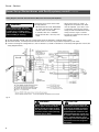
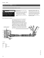
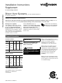
Installation Instructions
Supplement
for use by heating contractor
Please file in Service Binder
Direct Vent Systems,
Part No. Z005 875 (FDVS-4)
for Vitorond 100 boilers
Safety and Installation Requirements
Please ensure that these instructions are read and understood before commencing installation. Failure to comply with the
instructions listed below can cause product/property damage, severe personal injury, and/or loss of life.
Working on the equipment
The installation, adjustment, service,
and maintenance of this product must
be done by a licensed professional
heating contractor who is qualified and
experienced in the installation, service,
and maintenance of hot water boilers.
There are no user serviceable parts on
the boiler, burner, or control.
Ensure main power supply to
equipment, the heating system, and all
external controls has been deactivated.
Close main oil supply valve. Take
precautions in both instances to avoid
accidental activation of power during
service work.
Ensure that the installation
literature of other applicable
components is referenced.
General Information
Standard installation
Boiler
Model
VR1
Rear
inches
mm
inches
mm
inches
mm
Sides
Flue
Floor
-22
-27
-33
6
150
0
0
1
25
6
150
0
0
1
25
6
150
0
0
1
25
Combustibles
Boiler
Model
VR1
-22
-27
-33
Rear
inches
mm
inches
mm
inches
mm
inches
mm
6
150
0
0
1
25
6
150
6
150
0
0
1
25
6
150
6
150
0
0
1
25
6
150
Flue
Top*
Floor
Combustibles
* 24” with Vitotronic control.
The insulated oil direct vent system is
rated for a 1” clearance to
combustibles.
5351 050 v2.5 09/2012
Advise owner to keep direct vent
termination and air intake free of
debris, snow and ice.
WARNING
Viessmann will not assume any
responsibility for possible effects of
an obstructed air intake or exhaust
termination.
Alcove installation
Sides
IMPORTANT
NOTE: Surface discoloration on the
outside of the building may occur if the
burner is not properly adjusted.
Viessmann will not accept any
responsibility for such discoloration.
NOTE: Direct Vent exhaust system
operates under a positive pressure
developed by the burner. Make sure all
vent connections and observation port
on the boiler are sealed air-tight by
tightening screws and using high
temperature silicone sealant if
necessary.
NOTE: The vent components must be
supplied without any alteration except
for the length of the flex pipe to be cut
to the desired length.
Installation
Installation of Insulated Stainless Steel Flexible Oil Vent
Refer to Vitorond 100
Installation and Service
Instructions.
In addition to the following
instructions, also consult
Field Controls Direct Vent
System manual for detailed
instructions on how to install
the venting system.
Supports
max. 3’
Air intake
Ø4”
a
b
Exhaust
12” min. above
anticipated snow line
*Boiler-to-vent
transition adaptor
(stainless steel)
VRV-4
Vacuum
Relief
Valve
Smoke test port
R1
b=15’
a=20’
(max. 2 x 90°elbows)
Each 90° elbow = 3’ e.q.L.
R1=min. wall clearance 28”
(for min. bend radius of
flexible vent pipe)
Fig. 1
2
Avoid dips in the venting system when
using the flexible insulated stainless
steel oil vent.
The direct vent kit includes a VRV-4
vacuum relief valve which must be
installed in the air intake pipe as close
as possible to the burner when using a
Beckett burner (see Fig. 1).
*The direct vent kit includes a
Viessmann-specific stainless steel
boiler-to-vent transition adaptor.
IMPORTANT
Do not install the regular galvanized
vent pipe adaptor shipped with the
boiler. This galvanized vent pipe
adaptor is intended for chimney venting
application and therefore must be
discarded in a direct vent application.
5351 050 v2.5
Use a 4” to 3” reducer (not supplied)
to connect an intake pipe to the Riello
burner.
If no air intake is required a=0 then
provide combustion air supply to
mechanical room where the burner is
installed. The burner requires fresh air
for safe operation and must be installed
in a mechanical room where there are
provisions for adequate combustion
and ventilation air.
Burner - Beckett
Burner Set-up (Beckett)
Electrical connections (with Aquastat control)
WARNING
Electric shock hazard. Can cause
severe personal injury or loss of life if
power source, including service
switch on boiler, is not disconnected
before installing or servicing.
"
"
"
Installations must follow these codes
and requirements:
- National Electrical Code, ANSI/NFPA
70, latest edition and any addtional
national, state or local codes.
- In Canada, CSA C22.1 Canadian
Electrical Code Part 1 and any local
codes.
- Wiring must be N.E.C. Class 1. If
original wire as supplied with boiler
must be replaced, type 105°C wire
or equivalent must be used. Supply
wiring to boiler and additional control
wiring must be 14 ga. or heavier.
- Provide electrical ground at boiler as
required by codes.
All field supplied nominal 120 VAC voltage wiring must be sheathed in a flexible metal conduit.
Disconnect means, overload protection and low water cut-off must be provided as required by local codes.
Connect incoming line voltage HOT (L1) wire to terminal L1, and N to terminal L2 of the Honeywell high limit control (see
wiring diagram on page 5.
Burner wiring
IMPORTANT
The R7184 or GeniSys 7505P primary
control with valve-on delay (pre-purge)
and burner motor-off delay (post-purge
- factory default settings can be field
adjusted), requires a constant 120
VAC power source supplied to the
BLACK wire on the control (see wiring
diagram on following page).
1. The cover mounting plate is not a
conduit connection point. Pass
conduit and attached connector
through the front opening in the
mounting plate or through one of the
knockouts on either side of the cover
and attach it directly to the
burner-mounted 4x4 electrical
junction box.
Fig. 2
5351 050 v2.5
Legend
Cable strap (supplied)
Honeywell high limit control
Burner wiring harness (supplied)
Room thermostat wiring
WARNING
Ensure that burner wiring harness is
properly attached and secured to the
boiler side panel using the supplied
cable straps as depicted above. The
cable strap must be coiled on the
boiler side panel so that no slack is
left, allowing the burner/boiler door
to be swung open without
disconnecting the burner wiring
harness from the burner. Failure to
heed this warning may result in
personal injury.
1. Install thermostat on inside wall
away from influences of drafts, hot
or cold water pipes, lighting fixtures,
television, sun rays or fireplaces.
2. Follow instructions supplied with
room thermostat. If it has a heat
anticipator, set heat anticipator in
thermostat to match power
requirements of equipment
connected to it. Boiler wiring
diagrams give setting for standard
equipment.
3
Burner - Beckett
Burner Set-up (Beckett)
(continued)
Electrical connections (with Aquastat control) (continued)
WARNING
Electric shock hazard. Can cause
severe personal injury or loss of life if
power source, including service
switch on boiler, is not disconnected
before installing or servicing.
Installations must follow these codes
and requirements:
- National Electrical Code, ANSI/NFPA
70, latest edition and any addtional
national, state or local codes.
- In Canada, CSA C22.1 Canadian
Electrical Code Part 1 and any local
codes.
- Wiring must be N.E.C. Class 1. If
original wire as supplied with boiler
must be replaced, type 105°C wire
or equivalent must be used. Supply
wiring to boiler and additional control
wiring must be 14 ga. or heavier.
- Provide electrical ground at boiler as
required by codes.
white
black
red
ground
Burner wiring harness (supplied)
ground
1/4 quick
connect
insulated
flag
red
15” *
white
black
5351 050 v2.5
Fig. 3
4
Burner - Beckett
Burner Set-up (Beckett)
(continued)
Wiring diagram (with Aquastat control) with outdoor reset module
WARNING
Electric shock hazard. Can cause
severe personal injury or loss of life if
power source, including service
switch on boiler, is not disconnected
before installing or servicing.
"
"
"
Installations must follow these codes
and requirements:
- National Electrical Code, ANSI/NFPA
70, latest edition and any additional
national, state or local codes.
- In Canada, CSA C22.1 Canadian
Electrical Code Part 1 and any local
codes.
- Wiring must be N.E.C. Class 1. If
original wire as supplied with boiler
must be replaced, type 105°C wire
or equivalent must be used. Supply
wiring to boiler and additional control
wiring must be 14 ga. or heavier.
- Provide electrical ground at boiler as
required by codes.
All field supplied nominal 120 VAC voltage wiring must be sheathed in a flexible metal conduit.
Disconnect means, overload protection and low water cut-off must be provided as required by local codes.
Connect incoming line voltage HOT (L1) wire to terminal L1, and N to terminal L2 of the Honeywell high limit control (see
wiring diagram below).
5351 050 v2.5
Fig. 4
Legend
Oil solenoid valve
Ignition transformer
Burner motor
CAD cell flame detector
Burner grounding screw
R7184 Series primary control
with post-purge (factory default
setting: 30 sec. - can be field
adjusted; see Beckett burner
manual)
Factory-installed jumper
WARNING
Ensure that the burner cycles ON and
OFF on proper call for heat before
leaving the job site. Failure to do so
may lead to boiler runaway situation,
which may lead to property damage,
personal injury or death.
CAUTION
A field supplied manual reset high
limit control must be installed at the
outlet pipe of the boiler to interrupt
burner operation should the factory
supplied high limit control fail. This
field supplied high limit control must
be set 20°F above the setting of the
factory supplied high limit control.
The setting of this field supplied high
limit control must never be greater
than 220°F.
5
Burner - Beckett
Burner Set-up (Beckett burner with GeniSys primary control)
(continued)
Wiring diagram (Vitorond 100 with Beckett (NX) burner and Honeywell Aquastat)
WARNING
Electric shock hazard. Can cause
severe personal injury or loss of life
if power source, including service
switch on boiler, is not disconnected
before installing or servicing.
"
"
"
Installations must follow these codes
and requirements:
- National Electrical Code, ANSI/NFPA
70, latest edition and any additional
national, state or local codes.
- In Canada, CSA C22.1 Canadian
Electrical Code Part 1 and any local
codes.
- Wiring must be N.E.C. Class 1. If
original wire as supplied with boiler
must be replaced, type 105°C wire
or equivalent must be used. Supply
wiring to boiler and additional control
wiring must be 14 ga. or heavier.
- Provide electrical ground at boiler as
required by codes.
All field supplied nominal 120 VAC voltage wiring must be sheathed in a flexible metal conduit.
Disconnect means, overload protection and low water cut-off must be provided as required by local codes.
Connect incoming line voltage HOT (L1) wire to terminal L1, and N to terminal L2 of the Honeywell high limit control (see
wiring diagram below).
Fig. 5
6
CAUTION
A field supplied manual reset high
limit control must be installed at the
outlet pipe of the boiler to interrupt
burner operation should the factory
supplied high limit control fail. This
field supplied high limit control must
be set 20°F above the setting of the
factory supplied high limit control.
The setting of this field supplied high
limit control must never be greater
than 220°F.
5351 050 v2.5
WARNING
Ensure that the burner cycles ON and
OFF on proper call for heat before
leaving the job site. Failure to do so
may lead to boiler runaway situation,
which may lead to property damage,
personal injury or death.
Burner - Beckett
Burner Set-up (Beckett)
(continued)
Electrical connections (with Vitotronic control)
WARNING
Electric shock hazard. Can cause
severe personal injury or loss of life if
power source, including service
switch on boiler, is not disconnected
before installing or servicing.
Installations must follow these codes
and requirements:
- National Electrical Code, ANSI/NFPA
70, latest edition and any addtional
national, state or local codes.
- In Canada, CSA C22.1 Canadian
Electrical Code Part 1 and any local
codes.
- Wiring must be N.E.C. Class 1. If
original wire as supplied with boiler
must be replaced, type 105°C wire
or equivalent must be used. Supply
wiring to boiler and additional control
wiring must be 14 ga. or heavier.
- Provide electrical ground at boiler as
required by codes.
Burner wiring
IMPORTANT
41
#41 plug-in connector
The R7184 primary control with
valve-on delay (pre-purge) and burner
motor-off delay (post-purge - factory
default settings can be field
adjusted), requires a constant 120
VAC power source supplied to the
BLACK wire on the control (see
wiring diagram on page 9).
1. The cover mounting plate is not a
conduit connection point. Pass
conduit and attached connector
through the front opening in the
mounting plate or through one of the
knockouts on either side of the cover
and attach it directly to the
burner-mounted 4x4 electrical
junction box.
Electrical connections
2.
1.Run the
plug-in connector cable of
the Vitotronic control down behind
the front panel of the boiler and out
through the bottom. (Fig. 5)
2.Connect the female
plug of the
burner to the male
plug of the
Vitotronic control. (Fig. 5)
1.
5351 050 v2.5
Fig. 6
7
Connections
Burner Set-up (Beckett) (continued)
Electrical connections (with Vitotronic control) (continued)
Room thermostat wiring
1. Install thermostat on inside wall
away from influences of drafts, hot
or cold water pipes, lighting fixtures,
television, sun rays or fireplaces.
5351 050 v2.5
2. Follow instructions supplied with
room thermostat. If it has a heat
anticipator, set heat anticipator in
thermostat to match power
requirements of equipment
connected to it. Boiler wiring
diagrams give setting for standard
equipment.
8
Connections
Burner Set-up (Beckett)
(continued)
Electrical connections (with Vitotronic control) (continued)
WARNING
Electric shock hazard. Can cause
severe personal injury or loss of life if
power source, including service
switch on boiler, is not disconnected
before installing or servicing.
Installations must follow these codes
and requirements:
- National Electrical Code, ANSI/NFPA
70, latest edition and any addtional
national, state or local codes.
- In Canada, CSA C22.1 Canadian
Electrical Code Part 1 and any local
codes.
- Wiring must be N.E.C. Class 1. If
original wire as supplied with boiler
must be replaced, type 105°C wire
or equivalent must be used. Supply
wiring to boiler and additional control
wiring must be 14 ga. or heavier.
- Provide electrical ground at boiler as
required by codes.
Viessmann #41-plug
control connection
BL
B4
O
S3
BK
T2
Closed end connectors are factory installed on
RED, ORANGE and BLUE wires. These RED,
ORANGE and BLUE wires may or may not be
used in your burner application. See wiring
diagram in this manual which is specific to your
burner application. Do not remove or cut any of
the closed end connectors of the RED, ORANGE
or BLUE wires, unless it is necessary to do so.
RED wire is live (120VAC) at all times. Do not
remove or cut its closed end connector unless it
is necessary to do so. Failure to heed the above
instructions may cause severe personal injury or
loss of life.
Blue
Burner wiring harness (supplied)
18” *
T1
W
N
G
G
R
L1
Jumper
RED
Fig. 7
5351 050 v2.5
Legend
BL
O
BK
W
G
R
Blue
Orange
Black
White
Green / Ground
Red
* If Beckett burner is being installed,
cut this length to 6” for connection
to burner junction box (located
under the burner primary control).
9
Connections
Burner Set-up (Beckett)
(continued)
Wiring diagram (with Vitotronic control)
WARNING
Electric shock hazard. Can cause
severe personal injury or loss of life if
power source, including service
switch on boiler, is not disconnected
before installing or servicing.
Installations must follow these codes
and requirements:
- National Electrical Code, ANSI/NFPA
70, latest edition and any additional
national, state or local codes.
- In Canada, CSA C22.1 Canadian
Electrical Code Part 1 and any local
codes.
Blue and orange wires not used in this
application. DO NOT cut or remove closed
end connector from the wires.
Burner junction box
G
WARNING
2
Ensure that the burner cycles ON and
OFF on proper call for heat before
leaving the job site. Failure to do so
may lead to boiler runaway situation,
which may lead to property damage,
personal injury or death.
BL
O
R
BK
R
BK
W
W
V
Factory
installed
jumper
41
- Wiring must be N.E.C. Class 1. If
original wire as supplied with boiler
must be replaced, type 105°C wire
or equivalent must be used. Supply
wiring to boiler and additional control
wiring must be 14 ga. or heavier.
- Provide electrical ground at boiler as
required by codes.
BL
O
T
T
O
T1
N
G
L1
W
G
R
N
G
L1
1 120 VAC
power supply
installer must
provide 15A
overcurrent
protection
41
Legend
Y
BL
BK
O
W
G
R
GY
BR
V
Yellow
Blue
Black
Orange
White
Green / Ground
Red
Gray
Brown
Violet
Refer to Vitotronic
200/300 (KW2/KW3)
for alternate connection
location of LWCO.
2
Vitotronic Control
(Refer to corresponding Vitotronic Control manual)
Fig. 8
10
120 VAC
power
supply
to boiler
Main
ON/OFF
switch
(field supplied)
Low water
cut-off
(if required)
(field supplied)
120 VAC receptacle
(field supplied)
Power supply. Provide disconnect
1 means and overload protection as
required.
2 Control case must be connected
to earth ground.
Legend
Oil solenoid valve
Ignition transformer
Burner motor
CAD cell flame detector
Burner grounding screw
R7184 Series primary control
with post-purge (factory default
setting: 30 sec. - can be field
adjusted; see Beckett burner
manual)
Factory-installed jumper
5351 050 v2.5
BK
T2
T2
O
Y
T1
B4
S3
BL
B4
S3
Y
Connections
Burner Set-up (Beckett burner with GeniSys primary control)
Wiring diagram (Vitorond 100 with Beckett (NX) burner, GeniSys control and Vitotronic control)
WARNING
Electric shock hazard. Can cause
severe personal injury or loss of life
if power source, including service
switch on boiler, is not disconnected
before installing or servicing.
Installations must follow these codes
and requirements:
- National Electrical Code, ANSI/NFPA
70, latest edition and any additional
national, state or local codes.
- In Canada, CSA C22.1 Canadian
Electrical Code Part 1 and any local
codes.
- Wiring must be N.E.C. Class 1. If
original wire as supplied with boiler
must be replaced, type 105°C wire
or equivalent must be used. Supply
wiring to boiler and additional control
wiring must be 14 ga. or heavier.
- Provide electrical ground at boiler as
required by codes.
WARNING
Ensure that the burner cycles ON and
OFF on proper call for heat before
leaving the job site. Failure to do so
may lead to boiler runaway situation,
which may lead to property damage,
personal injury or death.
5351 050 v2.5
VIESMANN
Fig. 9
11
Burner - Riello
Burner Set-up (Riello)
Electrical connections (with Aquastat control)
WARNING
Electric shock hazard. Can cause
severe personal injury or loss of life if
power source, including service
switch on boiler, is not disconnected
before installing or servicing.
"
"
"
Installations must follow these codes
and requirements:
- National Electrical Code, ANSI/NFPA
70, latest edition and any additional
national, state or local codes.
- In Canada, CSA C22.1 Canadian
Electrical Code Part 1 and any local
codes.
- Wiring must be N.E.C. Class 1. If
original wire as supplied with boiler
must be replaced, type 105°C wire
or equivalent must be used. Supply
wiring to boiler and additional control
wiring must be 14 ga. or heavier.
- Provide electrical ground at boiler as
required by codes.
All field supplied nominal 120 VAC voltage wiring must be sheathed in a flexible metal conduit.
Disconnect means, overload protection and low water cut-off must be provided as required by local codes.
Connect incoming line voltage HOT (L1) wire to terminal L1, and N to terminal L2 of the Honeywell high limit control (see
wiring diagram on page 12).
Burner wiring
using 2
1. Secure control harness
supplied cable straps
.
WARNING
Ensure that burner wiring harness is
properly attached and secured to the
boiler side panel using the supplied
cable straps as depicted above. The
cable strap must be coiled on the
boiler side panel so that no slack is
left, allowing the burner/boiler door
to be swung open without
disconnecting the burner wiring
harness from the burner. Failure to
heed this warning may result in
personal injury.
Room thermostat wiring
Fig. 10
2. Follow instructions supplied with
room thermostat. If it has a heat
anticipator, set heat anticipator in
thermostat to match power
requirements of equipment
connected to it. Boiler wiring
diagrams give setting for standard
equipment.
5351 050 v2.5
Legend
Burner and control harness, (see
wiring diagram on page 12)
Cable strap (supplied)
Honeywell high limit control
1. Install thermostat on inside wall
away from influences of drafts, hot
or cold water pipes, lighting fixtures,
television, sun rays or fireplaces.
12
Burner - Riello
Burner Set-up (Riello)
(continued)
Electrical connections (with Aquastat control) (continued)
WARNING
Electric shock hazard. Can cause
severe personal injury or loss of life if
power source, including service
switch on boiler, is not disconnected
before installing or servicing.
Installations must follow these codes
and requirements:
- National Electrical Code, ANSI/NFPA
70, latest edition and any addtional
national, state or local codes.
- In Canada, CSA C22.1 Canadian
Electrical Code Part 1 and any local
codes.
- Wiring must be N.E.C. Class 1. If
original wire as supplied with boiler
must be replaced, type 105°C wire
or equivalent must be used. Supply
wiring to boiler and additional control
wiring must be 14 ga. or heavier.
- Provide electrical ground at boiler as
required by codes.
white
black
red
ground
Burner wiring harness (supplied)
ground
1/4 quick
connect
insulated
flag
red
15” *
white
black
Fig. 11
5351 050 v2.5
* If Beckett burner is being installed,
cut this length to 6” for connection
to burner junction box (located
under the burner primary control).
13
Burner - Riello
Burner Set-up (Riello)
(continued)
Wiring diagram (with Aquastat control) with outdoor reset module
WARNING
Electric shock hazard. Can cause
severe personal injury or loss of life if
power source, including service
switch on boiler, is not disconnected
before installing or servicing.
"
"
"
Installations must follow these codes
and requirements:
- National Electrical Code, ANSI/NFPA
70, latest edition and any additional
national, state or local codes.
- In Canada, CSA C22.1 Canadian
Electrical Code Part 1 and any local
codes.
- Wiring must be N.E.C. Class 1. If
original wire as supplied with boiler
must be replaced, type 105°C wire
or equivalent must be used. Supply
wiring to boiler and additional control
wiring must be 14 ga. or heavier.
- Provide electrical ground at boiler as
required by codes.
All field supplied nominal 120 VAC voltage wiring must be sheathed in a flexible metal conduit.
Disconnect means, overload protection and low water cut-off must be provided as required by local codes.
Connect incoming line voltage HOT (L1) wire to terminal L1, and N to terminal L2 of the Honeywell high limit control (see
wiring diagram below).
Fig. 12
Post-purge
timer
A field supplied manual reset high
limit control must be installed at the
outlet pipe of the boiler to interrupt
burner operation should the factory
supplied high limit control fail. This
field supplied high limit control must
be set 20°F above the setting of the
factory supplied high limit control.
The setting of this field supplied high
limit control must never be greater
than 220°F.
14
Post-purge timer setting in conjunction
with Honeywell Aquastat Model
L7248C1006
IMPORTANT
If “Err4” fault occurs, set post-purge
timer to a maximum of 45 seconds.
Exceeding 45 seconds may lead to LED
error code “Err4” on the older version
of the Honeywell Aquastat.
5351 050 v2.5
CAUTION
Burner - Riello
Burner Set-up (Riello)
Electrical connections (with Vitotronic control)
WARNING
Electric shock hazard. Can cause
severe personal injury or loss of life if
power source, including service
switch on boiler, is not disconnected
before installing or servicing.
Installations must follow these codes
and requirements:
- National Electrical Code, ANSI/NFPA
70, latest edition and any additional
national, state or local codes.
- In Canada, CSA C22.1 Canadian
Electrical Code Part 1 and any local
codes.
- Wiring must be N.E.C. Class 1. If
original wire as supplied with boiler
must be replaced, type 105°C wire
or equivalent must be used. Supply
wiring to boiler and additional control
wiring must be 14 ga. or heavier.
- Provide electrical ground at boiler as
required by codes.
Room thermostat wiring
1. Install thermostat on inside wall
away from influences of drafts, hot
or cold water pipes, lighting fixtures,
television, sun rays or fireplaces.
2. Follow instructions supplied with
room thermostat. If it has a heat
anticipator, set heat anticipator in
thermostat to match power
requirements of equipment
connected to it. Boiler wiring
diagrams give setting for standard
equipment.
2.
Electrical connections
1. Run the
plug-in connector cable
ofthe Vitotronic control down behind
the front panel of the boiler and
out through the bottom. (Fig. 11)
1.
41
41
#41 plug-in connector
5351 050 v2.5
Fig. 13
2. Connect the female
plug of the
burner to the male
plug of the
Vitotronic control. (Fig. 11)
15
Burner - Riello
Burner Set-up (Riello)
(continued)
Electrical connections (with Vitotronic control) (continued)
WARNING
Electric shock hazard. Can cause
severe personal injury or loss of life if
power source, including service
switch on boiler, is not disconnected
before installing or servicing.
Installations must follow these codes
and requirements:
- National Electrical Code, ANSI/NFPA
70, latest edition and any addtional
national, state or local codes.
- In Canada, CSA C22.1 Canadian
Electrical Code Part 1 and any local
codes.
- Wiring must be N.E.C. Class 1. If
original wire as supplied with boiler
must be replaced, type 105°C wire
or equivalent must be used. Supply
wiring to boiler and additional control
wiring must be 14 ga. or heavier.
- Provide electrical ground at boiler as
required by codes.
Viessmann #41-plug
control connection
BL
B4
O
S3
BK
T2
Closed end connectors are factory installed on
RED, ORANGE and BLUE wires. These RED,
ORANGE and BLUE wires may or may not be
used in your burner application. See wiring
diagram in this manual which is specific to your
burner application. Do not remove or cut any of
the closed end connectors of the RED, ORANGE
or BLUE wires, unless it is necessary to do so.
RED wire is live (120VAC) at all times. Do not
remove or cut its closed end connector unless it
is necessary to do so. Failure to heed the above
instructions may cause severe personal injury or
loss of life.
Blue
Burner wiring harness (supplied)
18” *
T1
W
N
G
G
R
L1
Jumper
RED
Fig. 14
Blue
Orange
Black
White
Green / Ground
Red
5351 050 v2.5
Legend
BL
O
BK
W
G
R
16
Burner - Riello
Burner Set-up (Riello)
(continued)
Wiring diagram (with Vitotronic control) (continued)
WARNING
Electric shock hazard. Can cause
severe personal injury or loss of life if
power source, including service
switch on boiler, is not disconnected
before installing or servicing.
Installations must follow these codes
and requirements:
- National Electrical Code, ANSI/NFPA
70, latest edition and any additional
national, state or local codes.
- In Canada, CSA C22.1 Canadian
Electrical Code Part 1 and any local
codes.
2
G
NO
G
12 11
Capacitor
W
M
BK
BL
W
L
R
X
R
BK
N
W
O
BL
BL
O
GY
BK
R
BL
AL 1009
Burner Fan-Off
Timer
R
L1
Riello burner sub-base
1 Power supply. Provide disconnect means
and overload protection as required.
L1
G
Y
G
W
R
Factory
installed
jumper
G
T1
T2
BK
T1
S3
N
T2
B4
S3
N
O
W
2 Control case must be connected
to earth ground.
1
41
5351 050 v2.5
Legend
BL
BK
O
W
G
R
GY
BR
Y
Blue
Black
Orange
White
Green / Ground
Red
Gray
Brown
Yellow
Ensure that the burner cycles ON and
OFF on proper call for heat before
leaving the job site. Failure to do so
may lead to boiler runaway situation,
which may lead to property damage,
personal injury or death.
1 2 3 4 5 6 7 8
BL
BL
BR
BK
Oil valve
BRN
W
B4
9
W
BL
Blue wire not used
in this application.
DO NOT cut or
remove closed end
connector from
the wire.
WARNING
10
NC
Air pressure
switch
BK
41
- Wiring must be N.E.C. Class 1. If
original wire as supplied with boiler
must be replaced, type 105°C wire
or equivalent must be used. Supply
wiring to boiler and additional control
wiring must be 14 ga. or heavier.
- Provide electrical ground at boiler as
required by codes.
120 VAC
Power supply
installer must
provide 15A
overcurrent
protection
Main
ON / OFF
switch
(field supplied)
2
Vitotronic Control
(Refer to corresponding Vitotronic Control manual)
120 VAC
power
supply
to boiler
Low water
cut-off
(if required)
(field supplied)
Refer to Vitotronic
200 / 300 (KW2 / KW3)
manual for alternate
connection location of
LWCO.
120 VAC receptacle
(field supplied)
Fig. 15
17
Initial Start-up
Initial Start-Up
Beckett burner calibration
Boiler model
Model No.
Burner model
Beckett
Fuel type
oil
Pump pressure
psig
Oil nozzle
VR1-22
NX-VI 701
VR1-27
VR1-33
NX-VI 702
NX-VI 703
No. 2 fuel oil
190
175
Danfoss
n.a.
0.60x60°AS
n.a.
Delavan
0.50x60°B
n.a.
0.75x60°A/W
Hago
0.50x60°B
0.60x60°B
n.a.
Oil nozzle flow rate
GPH@psig
0.65@190
0.75@175
1.00@175
Air tube length
inches
mm
7
178
7
178
7
178
Air tube insertion
inches
mm
3¼
83
3¼
83
35/8
92
NX70LP
NX70LP
NX70LJ
6-slot
6-slot
9-slot
2.00
2.50
3.25
Air tube combination
Head type
Head setting
Air setting
see head setting
Static plate
n.a.
175
n.a.
Baffle
21844
21844
21844
Flange
32073
32073
32073
5351 050 v2.5
Fuel pump
18
Initial Start-up
Initial Start-Up
Riello burner calibration*1
Boiler model
Model No.
VR1-22
VR1-27 *1
VR1-33
BF3
BF3 *1
BF5
Burner model
Riello 40
Series
Fuel type
oil
Pump pressure
psig
175
175
140
Oil nozzle
Danfoss
n.a.
n.a.
n.a.
0.5x60°xSS
0.6x60°xW *3
0.85x60°xW *2
n.a.
n.a.
n.a.
0.65@175
0.75@175
1.00@140
No. 2 fuel oil
Oil nozzle
Delavan
Oil nozzle
Hago
Oil nozzle flow rate
GPH@psig
Air tube length
inches
mm
7
178
7
178
65/16
160
Air tube insertion
inches
mm
45/8
118
45/8
118
4¼
108
Turbulator setting
0.0
1.0
1.0
Air gate setting
3.7
5.0
4.0
IMPORTANT
*1
For VR1-27 boiler, replace installed nozzle with nozzle packaged with Riello burner.
Factory-installed nozzle.
*3 Nozzles must be installed by installer.
*2
5351 050 v2.5
Note: Riello oil burners are factory set for Vitorond 100, VR1-22, and -33 boilers and should
only require minor adjustments. Install appropriate nozzle and set the burner for model
VR1-27.
19
20
5351 050 v2.5
Technical information subject to change without notice.
Printed on environmentally friendly
(recycled and recyclable) paper.