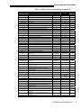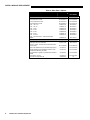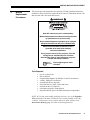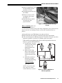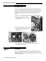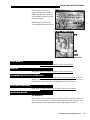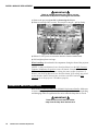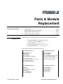
1
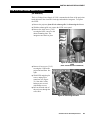
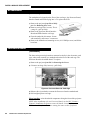
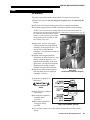
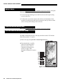
PROJECTION HEAD Parts & Module Replacement This document includes: 1 2 3 4 Ordering Parts ....................................................................................... page 1 Index of Replaceable Parts & Modules ................................................ page 2 Module Replacement Procedures ......................................................... page 5 CP2000-X Interconnect Diagram........................................................ page 30 When ordering replacement parts, please provide the following information: 1 Ordering Parts ◊ ◊ ◊ ◊ Christie Part Number for each item required (see Index of Parts & Modules) Projector Model (see projector rear panel) Projector Serial Number (see projector rear panel) Date of Manufacture (see projector rear panel) Order parts from one of the following locations: Christie Digital Systems, Inc. Christie Digital Systems, Inc. 809 Wellington St. North Kitchener, Ontario Canada N2G 4Y7 Tel. 519-744-8005 Toll Free 1-800-265-2171 (sales/parts) 10550 Camden Drive Cypress, CA 90630 Tel. 714-236-8610 Toll Free 1-886-880-4462 (sales/parts) Tool Free 1-800-221-8025 (tech support only—no parts ordering here) Tool Free 1-800-221-8025 (tech support only—no parts ordering here) Fax 519-749-3302 (Service) Fax 519-749-3136 (sales/parts) 013-100197-02 Rev. 1 (12/06) Fax 714-503-3375 (sales/parts) Christie Digital Systems Inc. Christie Digital Systems Inc. View Point 200 Ashville way Wokingham, Berkshire, RG41 2PL United Kingdom Tel. +44-118-926-6300 Fax +44-118-926-6322 627 Aljunied Road # 05-02 Biz Tech Cneter Singapore 389842 Tel. 65-6877-8737 Fax 65-6877-8747 CP2000-X Parts & Module Replacement 1 PARTS & MODULE REPLACEMENT Availability Parts identified throughout may not be available separately. In addition, some parts stocked as inventory are available only until the current supply lasts. All part numbers are subject-to-change. 2 Index of Replaceable Parts & Modules CP2000-X projection head replaceable parts and modules are listed in Table 1. Please refer to this table for each component/module name, part number, and the page number on which its replacement procedure begins. Note that CP2000-X ballast components are documented in the Roadie 25K Ballast Service Instructions, as these ballasts are identical. Other CP2000-X options and accessories are listed in Table 2. Locating Parts To locate or identify a CP2000-X module, refer to the CP2000 and Roadie 25K exploded views—most CP2000-X modules are used in one or both of these in the Projector models, thus a separate CP2000-X “exploded” assembly view has not been published. Components residing in the CP2000-X belly pan are the exceptions— they are not present in the other models of projection heads. Please see Figure 10. 2 CP2000-X Parts & Module Replacement PARTS & MODULE REPLACEMENT Table 1. CP2000-X Index of Replaceable Parts & Modules Exploded View Label# Module Part Number Part Number RoHS See page… 2 (Roadie 25K) AC Distribution Module 03-260736-02P 03-260736-52P 8 3 (Roadie 25K) AC Relay Module 03-260656-01P 003-110228-01 8 4 (Roadie 25K) AC Voltmeter 03-000489-01P 003-120073-01 8 Air Filter (6-pack) 03-001981-01P 03-001981-51P n/a n/a n/a n/a 7 (Roadie 25K) n/a 8 (Roadie 25K) Cathode Swivel Connector 03-900510-01P 03-900510-51P Cold Mirror 03-005027-02P 03-005027-52P Covers various 8 8 Douser Module (Shutter) 03-240108-01P 03-240108-51P n/a Enhanced Formatter Interface Board (EFIB) 03-260729-02P 03-260729-52P 8 8 n/a Ethernet Hub (not a Christie service part) n/a n/a 9 03-000172-04P 003-110264-01 10 003-000316 003-000316-02 10 11 (Roadie 25K) Fan — Card Cage 13 (Roadie 25K) Fan — Heat Exchanger 14 (Roadie 25K) Fan — Lamp Blower, 230V 03-000158-01P 03-000158-02P 10 15 (Roadie 25K) Fan — Side Intake (2 required) 03-000147-05P 003-110248-01 12 n/a 16 (Roadie 25K) n/a Flex Cables 50-pin (set of 6) 03-001947-01P 003-000850-01 12 Fold Mirror 03-005028-01P 03-005028-51P 13 n/a Fused Harnesses in Ballast 03-900595-01P 003-110128-02 18 (Roadie 25K) Igniter 03-000839-01P 003-120085-01 13 19 (Roadie 25K) Illumination Optics System (IOS) 03-240102-03P 003-000741-02 13 20 (Roadie 25K) Integrator Module 03-240100-01P 03-240100-51P 13 Interface Board (Secure-ready) 003-120031-02 003-120031-03 13 003-000150 003-000150-02 14 16 (CP2000) 17 (Roadie 25K) Interlock — Lamp Door (also incl. vane switches) 18 (Roadie 25K) LAD Fan (does not include filter) 03-900504-01P 03-900504-51P 15 19 (Roadie 25K) LAD Filter (does not include fan) Lamp Ballast, 7 kW Universal Switching (complete 03-001982-01P 03-001982-51P 15 38-814001-01 38-814001-51 16 n/a with housing) 25 (Roadie 25K) LampLOC Module 03-900517-01P 03-900517-51P 16 26 (Roadie 25K) Lens Mount Kit 03-900515-01P 03-900515-51P 18 27 (Roadie 25K) Light Engine (original style, available as a refurb only) Light Engine (FTP with 16MB memory on modular 03-240106R02P 004-000274 18 003-000274 003-000274-02 18 03-240103-01P 003-000740-01 18 27 (Roadie 25K) 29 (Roadie 25K) 31 (Roadie 25K) 30 (Roadie 25K) 17 (Roadie 25K) formatters) Light Sensor Module Liquid Cooling System (complete: pump, heat exchanger, reservoir) Liquid Cooling Reservoir (bottle, 2 hoses, 4 clamps) Liquid Cooling Heat Exchanger (exchanger, 2 hoses, 4 clamps) 03-900514-01P 03-900514-51P 20 03-001983-02P 003-100434-01 n/a 03-000879-01P 03-000879-51P n/a 25 33 (Roadie 25K) Liquid Cooling Pump (pump, 2 hoses, 4 clamps) 03-000876-01P 003-120109-02 32 (Roadie 25K) Low Voltage Power Supply (LVPS) 03-000674-01P 003-120076-01 23 28 (CP2000) Motherboard with Twin DVI 03-260694-03P 24 29 (CP2000) Processor Board, Series 1 03-000755-01P 35 (Roadie 25K) Reflectors, 12" Glass (incl. both front & rear) 03-240115-01P 003-110241-01 003-000847-01 004-000847-01 03-240115-51P 36 (Roadie 25K) Reflector Shield (Rear) 03-006917-02P 03-006917-52P 26 37 (Roadie 25K) Stepper Driver Board (SDB) 03-260693-03P 003-110242-01 26 System Supervisor Module (SSM) Temperature Sensors (set of 2 for R/B DMDs, or 03-260674-02P 003-110243-01 26 003-000313 003-000313-02 27 Touch Panel Controller (incl. 24V Power Supply) 03-900506-01P 03-900506-51P 27 UV Filter Vane Switch — Exhaust Duct (also incl. other 2 03-008003-01P 03-008003-51P 27 03-900511-01P 03-900511-51P 27 03-900511-01P 03-900511-51P 28 03-008004-02P 03-008004-52P 29 33 (CP2000) n/a n/a 38 (Roadie 25K 22 (Roadie 25K 22 (Roadie 25K 39 (Roadie 25K prism or integrator) interlocks) Vane Switch — Lamp Fan (also incl. other 2 interlocks Yellow Notch Filter 24 26 CP2000-X Parts & Module Replacement 3 PARTS & MODULE REPLACEMENT Table 2. Other Parts / Options Part Name / Description Part Number RoHS Part Number 03-000695-01P 03-000696-01P 03-000697-01P 03-000698-01P 38-809079-01 38-809061-01 38-809052-01 38-809053-01 38-809069-01 38-809081-01 38-809080-01 003-000598-02 003-000599-02 003-000600-02 003-000601-02 38-809079-51 38-809061-51 38-809052-51 38-809053-51 38-809069-51 38-809081-51 38-809054-51 38-809054-01 38-813019-51 38-813019-02 38-813019-52 34-001999-03P 34-001999-03P 003-000275 003-000275-02 003-000168 003-000168-02 003-000326 003-000326-02 003-000078 598900-095 003-000078-02 n\a LENSES Lamp: 2KW Xenon CDXL Lamp: 3KW Xenon CDXL Lamp: 4.5KW Xenon CDXL Lamp: 6KW Xenon CDXL Lens, 1.25-1.45:1 Lens, 1.45-1.8:1 Lens, 1.8-2.4:1 Lens, 2.2-3.0:1 Lens, 3.0-4.3:1 Lens, 4.3-6.0:1 Lens, 5.5-8.5:11 Lens, 1.25x Anamorphic—requires anamorphic adapter OTHER Anamorphic Adapter (manual)—required for anamorphic lens. Non-motorized. TPC 50 ft. Cable—connects TPC to Ethernet and TPC power supply Spare Lens Stabilizer Kit (one included with projector) Blower Stabilizer Upgrade (already included in units manufactured after Aug. 30, 2005) Pump Stabilizer Upgrade Kit (included with CP2000-X model) Convergence Tool Kit Protective Clothing Safety Kit 4 CP2000-X Parts & Module Replacement PARTS & MODULE REPLACEMENT 3 Module Replacement Procedures This section provides instructions for replacing CP2000-X modules and service assemblies, many of which are similar to those in the CP2000 and/or Roadie 25K and accessed with a few minor differences. WARNINGS Read ALL instructions prior to disassembly. Module Replacement Procedures must be performed by qualified service personnel only. Non-insulated dangerous voltages may be exposed. Always disconnect from AC prior to disassembly. Observe all electrostatic precautions. Use a grounded wrist strap when handling electronic assemblies. Once you have turned off the projector, allow the cooling fans to automatically turn off before disconnecting from AC and opening the projector. This will take about 5 minutes. Gloves Required Wear supplied gloves when indicated. Tools Required • • • • • • • • • key for security locks flat screwdriver long and short magnetic-tip Phillips #1 and #2 screwdrivers “stubby” Phillips #2 screwdriver assorted ball drivers (imperial) metric ball drivers (1mm, 2.5mm and 3mm) assorted nut drivers (imperial) electrostatic protective strap and pad disposable Nitrile gloves (included with optical components) NOTE: 1) To locate each module within the projector, refer to the Exploded Views for Roadie 25K and/or CP2000. 2) To re-install a module, follow the “removal” instructions in reverse unless otherwise noted. 3) Refer to the Interconnect Drawing (page 30) when reconnecting harnesses. CP2000-X Parts & Module Replacement 5 PARTS & MODULE REPLACEMENT REMOVING THE COVERS (1-5 minutes each) WARNINGS • Fully disconnect from AC before removing a cover, particularly those at the front of the projection head. • Never operate the projector or run its fans without all covers installed. Front Lid Remove the front lid for service procedures of the opto-electronic processing modules residing in the projection head. Unlock the lid. 2) Raise the lid and pull its two tabs out from the opposite side from the latch. Set aside. Replace by inserting the 2 tabs into the hinge slots, and lowering the lid into place. Turn handle/latch to secure. 1) Figure 1. Front Lid Lamp Door Unlock lamp door near top edge, and lower the door (see right). If desired, release the tether (NON-OPERATOR’S SIDE) and spring mechanism located near the rear corner and remove the door entirely. Figure 2. Lamp Door Filter Door See right. Remove 2 corner screws from top edge of filter door, and lift off door. To replace, insert bottom tabs into slots and secure with screws. Figure 3. Filter Door Exhaust Grille See right. Remove 2 screws from top edge of exhaust grille, and lift off grille. To replace, insert bottom tabs into slots and secure with screws. Figure 4. Exhaust Grille 6 CP2000-X Parts & Module Replacement PARTS & MODULE REPLACEMENT Igniter Door See right. Unlock igniter door near top edge, and lower the door. If desired, release the tether and spring mechanism located near the rear corner and remove the door entirely. Figure 5. Igniter Door Rear Panel NOTE: If the TPC is mounted to the projector, remove the TPC first by loosening its ball arm/clamp, and disconnecting the cable. Remove 12 Phillips screws securing the rear panel to the projection head frame. Remove panel and set aside. Figure 6. Rear Panel Rear Lid 1) See Figure 7. below. Detach external ducting from the round duct opening at the top of the projection head. 2) Open/remove igniter door and lamp door. 3) Disconnect harness (2 connectors: red in middle, black for vane switch) from the exhaust vane switch. Route the wiring down into the igniter compartment. 4) Remove 4 screws from the underside of the rear lid (both door channels). 5) Lift lid off and set aside. When re-installing, make sure to re-connect the vane switch harness. Figure 7. Removing the rear lid Belly Pan Remove the belly pan for access to the Ethernet hub, hub power supply and TPC power supply, or to route the liquid cooling hoses to the quick-release connectors in the light engine compartment. Place a stable 4” support under the front and rear of the projector. 2) Remove 8 screws (4 each side) from the belly pan. 3) Slide the belly pan out from under the unit. 1) Figure 8. Belly Pan CP2000-X Parts & Module Replacement 7 PARTS & MODULE REPLACEMENT AC DISTRIBUTION MODULE (ACDM) (15 minutes) The AC Distribution Module is located in the igniter area between the lamp blower and the liquid cooling system. To remove: Remove igniter door. 2) Remove lamp blower vane switch bracket (one 3/8” nut). 3) Remove the ACDM mounting plate (3 screws), and lift the assembly from its slotted-hole mount on the interior wall. See right. 4) Disconnect 2 ACDM ground wires from the projector floor (1 screw). 5) Disconnect all connectors from the ACDM, and swap on to the new ACDM. When reconnecting: 1) Connect pairs of brown and blue wires with brown on top, and blue on bottom. AC RELAY MODULE Refer to the CP2000/XP2000 Parts & Module Replacement Booklet. AC VOLTMETER Refer to the Roadie 25K Parts & Module Replacement Booklet. COLD MIRROR Refer to the CP2000/XP2000 Parts & Module Replacement Booklet. DOUSER (SHUTTER) Refer to the CP2000/XP2000 Parts & Module Replacement Booklet. ENHANCED FORMATTER INTERFACE BRD. (EFIB) (15 minutes) The three main processing boards are mounted vertically in the electronics card cage, where each connects to a motherboard on the floor of the card cage. The Enhanced Formatter Interface Board (EFIB) is closest to the light engine, with 3 pairs of flex cables attached. To replace: Remove the projector front lid. See Removing the Covers. 2) Remove card cage lid (6 screws)—pull firmly. 1) 8 CP2000-X Parts & Module Replacement PARTS & MODULE REPLACEMENT 3) 4) 5) 6) 7) Disconnect 6 flex cables (3 pairs) and 3 power cables from the EFIB. See right. Disconnect the other end of the 6 flex cables from the light engine (see light engine instructions). Figure 9. EFIB Connectors Discard, as the flex cables should not be re-used. Release 2 side ejectors to unseat the EFIB from the motherboard. Pull straight up from card cage. When re-installing, orient the EFIB so that its components face the front of the projector. Double-check dip switch settings as indicated in the separate instructions supplied in the kit. Re-connect using new flex cables—make sure to follow the red-green-blue labeling (Figure 9.), and route properly to the corresponding light engine location. See also flex cables. WARNING Flex cables and their connectors are fragile. Use care when handling. NOTE: After installation of a new EFIB, run the DLP Cinema™ Firmware Installation Program to ensure all boards—Interface, Processor, EFIB and modular formatters—are running the same version of software. ETHERNET HUB (10 minutes) NOTE: Replacement hubs are not available from Christie. The Ethernet hub is Velcro™-mounted on the underside of the projector, protected by the belly pan (see Figure 10). To move or replace: Remove the belly pan. See Removing the Covers. 2) At the Ethernet hub, disconnect all devices. 3) Release the Velcro™ strap securing the hub to the interface plate, and replace with desired hub. 1) CP2000-X Parts & Module Replacement 9 PARTS & MODULE REPLACEMENT ETHERNET HUB POWER SUPPLY (10 minutes) The Ethernet hub power supply is Velcro™-mounted on the underside of the projector (see Figure 10.), protected by the belly pan. To move or replace: Remove the belly pan. See Removing the Covers. 2) Disconnect the Ethernet hub power supply. 3) Release the Velcro™ strap securing the power supply to the interface plate, and replace with new Figure 10. Belly Pan Area for TPC Power and Ethernet power supply. 1) FAN (CARD CAGE) Refer to the CP2000/XP2000 Parts & Module Replacement Booklet. FAN (HEAT EXCHANGER) (20 minutes) The heat exchanger’s fan is secured to the heat exchanger and mounted with the pump in the igniter area. To replace this fan, remove the pump/heat exchanger assembly as described in the Pump instructions later in this booklet. With the assembly pulled out of the igniter area (see Figure 29.), you can access the fan screws and swap a new fan in place. When re-installing, make sure connections and lead dress are correct. Swap the finger guard on to the new fan. FAN (LAMP BLOWER) (45 minutes) The lamp fan is mounted in the rear corner of the igniter compartment. To remove: 1) 10 Remove igniter door, lamp door, rear panel, and rear lid. See Removing the Covers. CP2000-X Parts & Module Replacement PARTS & MODULE REPLACEMENT Remove Lamp Blower Vane Switch/mounting bracket assembly (3/8” nut). 3) Disconnect the blower from the ACDM. 4) Remove 2 screws (5/32”) securing the fan in place. See Figure 11. 5) Rotate the blower and lift out at the top of the projection head. 2) Figure 11. Remove Blower Mounting Screws When re-installing, make sure the “nozzle” of the blower is 1) well-centered with the opening to the lamp compartment, and 2) flush with the interior firewall—not leaning toward or on this wall. Install the blower as follows: Swap the blower-to-ACDM harness on to the new blower. 2) Begin with lamp side facing up, bottom facing the lamp compartment. 3) Lower into the projector and rotate into place. Position as far to the rear of the projector as possible—provide 1/8” clearance at the vane switch. If the unit has been upgraded with silicone stabilizing hardware shown in Figure 12., please note the following: In older bases, invert the rearmost silicone mount (1) as shown—the smaller diameter end faces down. Make sure the lamp blower seats properly on all three anti-vibration silicone mounts (Figure 12.). Add rubber washers as necessary for proper leveling and positioning of the blower. See “When re-installing” note, above. 1) NOTE: Original units may also require one rubber washer added at (1) and (2). Figure 12. Silicone Stabilizers at Mounts (optional) CP2000-X Parts & Module Replacement 11 PARTS & MODULE REPLACEMENT FANS (SIDE INTAKES) (20 minutes each) Two identical “intake” fans are mounted side-by-side on the lamp side of the projection head. Although the filtered air actually enters on the opposite side of the projector—the igniter side—these fans pull the air across the front area of the projection head and are considered intake fans. Either fan can be replaced independently after removing the louvered exhaust grille/shield from the projector. Remove projector front lid and exhaust grille. See Removing the Covers. 2) Make sure each fan harness is labeled before disconnecting from the SSM (P2 and P3). See Figure 13. 1) 3) From outside, remove four corner 7/64” hex mounting screws from the desired fan, and remove the fan from the projector. See Figure 15. below. Figure 13. Side Intake Fans Figure 14. Side Intake Fans 4) When installing a new fan, finger-tighten only—do not over-tighten or compress the rubber isolators. FLEX CABLES Gloves Required (10 minutes) The 3 pairs of identical flex cables routed between the Enhanced Formatter Interface Board (EFIB) and the light engine should be replaced whenever either of these modules is replaced. The cables are available separately as well as with the EFIB and light engine. 12 CP2000-X Parts & Module Replacement PARTS & MODULE REPLACEMENT For each pair of flex cables, connect the top cable from the EFIB to the top connector on the corresponding modular formatter in the light engine. Bottom cables connect to the corresponding bottom connector. Figure 15. Flex Cable Connections FOLD MIRROR Refer to the Roadie 25K Parts & Module Replacement Booklet. IGNITER Refer to the Roadie 25K Parts & Module Replacement Booklet. ILLUMINATION OPTICS SYSTEM (IOS) Refer to the CP2000/XP2000 Parts & Module Replacement Booklet with one change: you must remove the front belly pan (four 5/32” hex screws) to access the mounting screws under the overhanging portion of the projector. INTEGRATOR MODULE Refer to the CP2000/XP2000 Parts & Module Replacement Booklet. INTERFACE BOARD (10 minutes) The three main processing boards are mounted vertically in the electronics card cage, where each connects to a motherboard on the floor of the card cage. The Interface Board is the board furthest from the light engine. To replace: CP2000-X Parts & Module Replacement 13 PARTS & MODULE REPLACEMENT IMPORTANT Back up configuration data files (source, screen, MCGD and TCGD) before removing the Interface Bd. Remove the projector front lid. See Removing the Covers. 2) Remove card cage lid (6 screws). This may be a snug fit—pull up firmly. 1) Figure 16. Interface Board in CP2000-X Card Cage Release 2 side ejectors to unseat the Interface from the motherboard. 4) Pull straight up from card cage. 3) When installing: Orient board with components facing the front of the projector. NOTES: 1) After installation of a new Interface Board, run the DLP Cinema™ Firmware Installation Program to ensure all boards—Interface, Processor, EFIB and modular formatters—are running the same version of software. 2) Restore your back-up data to the new Interface board. 3) IP settings are stored on the Interface board. You may have to connect via RS232 and use DCP Librarian to set the projector’s IP address properly. INTERLOCK SWITCH (LAMP DOOR) Refer to the CP2000/XP2000 Parts & Module Replacement Booklet. Make sure to secure cabling away from the interlock arm to prevent the arm from pinching and damaging cables in a guillotine-like action when the lamp door is closed. IMPORTANT Dress and secure all interlock cables away from the lamp door interlock arm. 14 CP2000-X Parts & Module Replacement PARTS & MODULE REPLACEMENT LAMINAR AIRFLOW DEVICE (LAD) (20 minutes) The Laminar Airflow Device (LAD) consists of a small fan and filter mounted in a plastic frame and secured to the floor of the projection head, adjacent to the corner brace on the operator’s side. To remove the LAD for fan replacement: NOTE: To replace the filter only, open the projector lid and skip to Step 8. 1) 2) 3) 4) 5) 6) 7) Remove the projector front lid. See Removing the Covers. Disconnect the LAD fan from the SSM P7. Remove the 3 air hoses from the LAD. Remove 2 Phillips screws securing the LAD to the projection head floor or, in newer units, to a mounting bracket that slightly changes the orientation of the assembly. Tilt the LAD and carefully lift out of the projector between the integrator and the intake fans. Remove the fan from the plastic frame (four 3/32” hex screws) and swap in a new fan. Re-connect the air hoses as shown. Figure 17. Hoses 8) To replace the filter only, slide the filter out towards the intake fans and replace with a new filter. Do not push on the filter material. NOTE: Visually check the LAD filter whenever the side air filter is replaced. Change when the LAD filter appears grey/brown—this material cannot be cleaned. After re-installing the LAD filter, run the projector briefly Figure 18. Replacing the LAD filter only CP2000-X Parts & Module Replacement 15 PARTS & MODULE REPLACEMENT without the air hoses connected to the LAD. This will prevent any old filter dirt or new shavings that have rubbed off the filter lining from being deposited directly on the DMDs. Then reconnect LAD hoses as shown. LAMP BALLAST Refer to the Roadie 25K Ballast Service Instructions supplied with the ballast. LampLOC™ MODULE (45 minutes) The system of sensors and motors for controlling lamp position is a single module mounted near the rear wall of the projection head, under the lamp/reflector cooling duct. To replace the LampLOC module: Remove the TPC if present on projector. See TPC. 2) Remove the projection head rear panel, rear lid and lamp door. See Removing the Covers. 3) Remove the lamp (see the User’s Manual provided with the projector). 4) Manually move the vertical (Y) adjustment as low as possible by turning the “Y” thumbwheel counterclockwise. This wheel is Figure 19. Adjust “Y” to lower position just above and parallel to the LampLOC mounting plate. See Figure 19. 1) 5) REMOVE THE LAMP COOLING COMPARTMENT/DUCT: 16 CP2000-X Parts & Module Replacement Remove the cathode swivel nut by disconnecting 3 cathode wires and removing the rear hardware. Route wires outside of duct (down through the hole). See Error! Reference source not found.. Figure 20. Remove Cathode Connector Nut (NOTE: There is no PCB Wire in CP2000-X) PARTS & MODULE REPLACEMENT 6) Remove the sensor flag (see right). Remove the small floor insert surrounding the cathode post (see Figure 21). Remove 2 screws (7/64”) securing the top and bottom of the lamp cooling compartment to the projection head firewall. See Figure 22. Figure 21. Flag and Shield Remove 4 screws (3/16”) securing the LampLOC Figure 22. Lamp Cooling Compartment module—including its Screws mounting plate—to the projection head floor. See Figure 23. Figure 23. Remove LampLOC™ Mounting Screws CP2000-X Parts & Module Replacement 17 PARTS & MODULE REPLACEMENT Tilt the LampLOC/duct assembly towards the rear of the projector. At this point, the duct can be pulled off the LampLOC module and out of the projector (Figure 24). It is a tight fit—pull blower away for better clearance. 8) Remove the LampLOC module from the projector, and swap in a new module. 7) After installation, doublecheck SDB connections, then reset LampLOC. Figure 24. Tilt and Remove the Lamp Cooling Compartment/LampLOC Assembly LENS MOUNT Refer to the CP2000/XP2000 Parts & Module Replacement Booklet. LIGHT ENGINE Refer to the CP2000/XP2000 Parts & Module Replacement Booklet. LIGHT SENSOR MODULE (10 minutes) The Light Sensor Module (LSM) is located in the front corner of the projection head, just above the SSM. To replace: 1) 18 Remove the projector front lid. See Removing the Covers. CP2000-X Parts & Module Replacement PARTS & MODULE REPLACEMENT Remove 2 screws (5/32”) securing the LSM to the projector. See Figure 25. 3) Disconnect the LSM harness, and remove the sensor from projector. 2) Figure 25. Light Sensor Module Checking Light Sensor Module Readings: After installation, make sure to reset LampLOC and, if desired, recalibrate the min/max footlamberts. Also check light output readings during adjustment of LampLOC. Ideally, these values should change proportionately and “without stopping” as the lamp moves, and produce a good curve across the range of adjustment. If in doubt, after LampLOC is done, adjust power level from minimum to maximum and make sure light reading increases in proportion to power level. In rare cases, if you find that the sensor receives too much light and oversaturates, and is unable to produce the Figure 26. Apply Silicone if needed proportional light output readings (rare) expected during use of LampLOC, add a small amount of silicone (see right) to block some of the light. Use enough to produce a valid curve of readings, and apply only on the side areas as shown. NOTE: Silicone is rarely needed for any CP model, including CP2000-X. CP2000-X Parts & Module Replacement 19 PARTS & MODULE REPLACEMENT LIQUID COOLING SYSTEM (40 minutes) NOTE: See also Pump and Fan, Heat Exchanger. The liquid cooling system consists of a pump, coolant reservoir, and heat exchanger/fan linked together with clear hoses and mounted between the lamp blower and the igniter. To access and replace this system: Remove the projector lid, igniter door, rear lid and belly pan. See Removing the Covers. 2) Disconnect the pump motor and heat exchanger/fan from the ACDM. 3) Reaching into the light engine area, depress both of the quick-release connectors linking the 2 hoses from the light engine to the cooling components in the igniter area: Stand on the lamp side of the projector. Insert hand between the card cage and the hose link cover (see right). Depress the connectors to release hoses, pushing toward the front of the projector. Carefully pull hoses free at the underside of the projector. 1) 4) In the igniter area, remove the reservoir cradle (2 nuts)—the reservoir will still be attached via hose to the pump. See right. Figure 27. Access to the Quick-Release Connectors Figure 28. Remove Reservoir Cradle 20 CP2000-X Parts & Module Replacement PARTS & MODULE REPLACEMENT Remove four 5/32” hex screws securing the pump mounting bracket to the base the projector. The interior screw nearest the heat exchanger is very difficult to reach. 6) To remove the pump assembly, tilt it toward the front and middle of the projector—this may take several tries, but the entire heat exchanger/pump assembly can be removed via the igniter door opening. 5) Re-installation: Figure 29. Cooling Components Out PROPER ROUTING TO LIGHT ENGINE: At the underside of the projector, make sure to reconnect the hoses correctly: Heat exchanger to red (CP2000-X lamp side) Reservoir to blue (CP2000-X air filter side) FILLING: The system is subject to air locks upon filling, particularly if hose lines are significantly curved. For best results, fill before securing the new cooling system in the projector— spread lines out as flat and straight as possible before adding liquid coolant. Eliminate any air locks— liquid must be continuous, with no gaps or bubbles. IF A SINGLE COOLING COMPONENT WAS REPLACED: To Figure 30. Proper Hose Reconnection fill a system already installed within the projector (for example, when you have replaced only the pump): CP2000-X Parts & Module Replacement 21 PARTS & MODULE REPLACEMENT 1. 2. 3. 4. 5. Remove the belly pan so that the hosing under the projector is visible. Fill the reservoir ¾ full. Power up the projector. Close the douser/shutter. Watch closely for airlocks in the lines, particularly to and from the pump—you may have to pinch the hoses repeatedly to eliminate airlocks and encourage flow. 6. Run as necessary to eliminate all air bubbles. Make sure the pump is not running “dry”. 7. Power down and top up the reservoir—it should be ½-¾ full when done. 8. Power up and double-check for airlocks. ROUTE THE RESERVOIR-TO-PUMP HOSE: Make sure to route the reservoir-topump hose 1) around the vane switch and 2) under the blower (see Figure 31). A longer length of hose is included for upgrading older units in which the original shorter routing is prone to kinking. Figure 31. New Reservoir-to-Pump Hose Routing IMPORTANT: RECOMMENDED COOLANT Use low silica Prestone 50% Premix Anti-Freeze. Other solutions may cause clogging or other serious malfunctions. OTHER: If Prestone 50% Premix Anti-Freeze (a 50/50 mix of de-ionized water and low silica ethylene glycol) is not available, mix your own 50/50 solution of distilled water and a low-silica ethylene glycol (anti-freeze). Low silica solutions are less abrasive to the flexible tubing used in the projector. Avoid biodegradable types. 22 CP2000-X Parts & Module Replacement PARTS & MODULE REPLACEMENT LOW VOLTAGE POWER SUPPLY (LVPS) (30 minutes) The Low Voltage Power Supply (LVPS) is mounted to the floor of the projection head, adjacent to the electronics card cage and under the integrator. To replace the LVPS: Remove the projector front lid and exhaust grille. See Removing the Covers. 2) With the exhaust grille out, remove the LVPS access panel. 3) Remove the single screw (7/64”) securing the black “snood” to the douser mounting plate. The integrator can remain in place. 1) Figure 32. Remove snood above LVPS Remove 4 hex screws (7/64”) securing the LVPS to the projection head floor. See right. 5) With LVPS angled up for access, unplug all its connectors (see Figure 33). Note that 3 of the harnesses are secured with Phillips screws. 6) Pull out from the side of the projector, through the access hole. 4) (NOTE: SHOWN WITHOUT INTEGRATOR) Figure 33. Removing the LVPS CP2000-X Parts & Module Replacement 23 PARTS & MODULE REPLACEMENT MOTHERBOARD (25 minutes) The motherboard is located on the floor of the card cage—the Processor Board, Interface Board and EFIB all plug into it. To replace this PCB: 1) 2) 3) 4) 5) Remove the projector front lid and belly pan. See Removing the Covers. Remove card cage lid (6 screws). This is a snug fit—pull up firmly. Remove the Processor Board, Interface Board and EFIB from the card cage. From the underside, disconnect 10 nuts with stand-offs, and remove 3 connectors. Remove the Motherboard mounting screws (10-12 Phillips screw) and lift the board out. PROCESSOR BOARD (10 minutes) The three main processing boards are mounted vertically in the electronics card cage, where each connects to a motherboard on the floor of the card cage. The Processor Board is the middle board. To replace: Remove the projector front lid. See Removing the Covers. 2) . Remove card cage lid (6 screws)—pull firmly. 1) Figure 34. Processor Board in Card Cage Release side ejector hooks to unseat the Processor from the motherboard. 4) Pull straight up from card cage. 3) When installing, orient board with components facing the front of the projector. NOTE: After installation of a new Processor Board, run the DLP Cinema™ Firmware Installation Program to ensure all boards—Interface, Processor, EFIB and modular formatters—are running the same version of software. 24 CP2000-X Parts & Module Replacement PARTS & MODULE REPLACEMENT PUMP (30 minutes) The pump is part of the liquid cooling system. To replace the pump only: Remove the projector rear lid, belly pan and igniter door. See Removing the Covers. 2) Fully drain all coolant from the system (refer to separate instructions). 3) Disconnect pump from the ACDM, and remove both hoses from the pump. NOTE: Later units have gear clamps that can be loosened and reused. In earlier projectors having permanent hose connections, you must cut or pry off the old hosing and discard the clamps. Each service kit includes gear clamps for upgrading units in which the old style clamps were used. 1) Remove the 4 screws securing the isolation bracket (for pump and heat exchanger) to the projector floor. The interior screw nearest the heat exchanger is very difficult to reach but it can be done. 5) Slightly rotate the pump/bracket assembly to the front (clockwise), and remove it from the projector—see right. Rest the assembly on the open igniter door—the liquid cooling hoses should provide enough clearance without having to be disconnected. 6) Remove the pump isolation bracket from the pump (4 screws) and heat exchanger (3 screws). 4) 7) Figure 35. Removing the Pump Assembly (SHOWN WITH HOSES STILL IN PLACE) Swap the new pump on to the bracket. IMPORTANT Secure hardware as shown. Secure the heat exchanger to the bracket. 9) Re-install the completed assembly in the projector. 10) Re-connect pump hoses using gear clamps Figure 36. Hardware at Pump provided. 11) To refill the system, refer to the separate instructions provided with the pump. 8) CP2000-X Parts & Module Replacement 25 PARTS & MODULE REPLACEMENT REFLECTOR(S) Refer to the CP2000/XP2000 Parts & Module Replacement Booklet, noting the following differences: To access the top mounting screw at the firewall, move the liquid cooling reservoir aside first. To lift out the cast reflector mount (with reflectors still attached), tilt the assembly towards the front and rotate the innermost side up. Remove anode yoke to avoid possible damage to the reflectors. STEPPER DRIVER BOARD (SDB) Refer to the CP2000/XP2000 Parts & Module Replacement Booklet. SYSTEM SUPERVISOR MODULE (SSM) (15 minutes) The SSM is mounted to the floor of the projector between the LVPS and the front of the projector. To replace: 1) Remove the projector front lid. See Removing the Covers. 2) If not already done, carefully label all fan and temperature harnesses so they can be reconnected correctly upon reinstall (see right). Then disconnect all harnesses from the SSM. Figure 37. Label SSM Harnessing 26 CP2000-X Parts & Module Replacement PARTS & MODULE REPLACEMENT 3) Remove 6 Phillips screws securing the SSM to the projector floor. See right. When re-installing the SSM, make sure to: Connect the green GND wire to a mounting screw on the SSM. Connect all harnessing correctly. TEMPERATURE SENSORS Refer to the Thermal Sensor Installation Instructions supplied with the thermal sensor service kit. Figure 38.SSM Mounting Screws TOUCH PANEL CONTROLLER (TPC) Refer to the CP2000/XP2000 Parts & Module Replacement Booklet. 24V POWER SUPPLY FOR TPC (10 minutes) NOTE: Not available separately—included with Touch Panel Controller. The 24V power supply is mounted to the underside of the projector, protected by the belly pan (refer back to Figure 10.). To move or replace: Remove the belly pan. See Removing the Covers. 2) Disconnect the 24V power supply. 3) Release the power supply from its bracket secured to the interface plate, and replace with new power supply. 1) UV FILTER Refer to the CP2000/XP2000 Parts & Module Replacement Booklet, noting the addition of washers used as spacers for each clip. VANE SWITCH: EXHAUST (10 minutes) The vane switch for the exhaust duct is located just inside the projector’s top duct. To replace: 1) Disconnect the user’s exhaust ducting from the top duct of the projector (up to 4 screws). CP2000-X Parts & Module Replacement 27 PARTS & MODULE REPLACEMENT Figure 39. Vane Switch in Exhaust Duct Remove 2 nuts (¼”) securing the vane switch to its mounting bracket. 3) Disconnect the harness from the switch, and remove the switch. 2) NOTE The Interlock Kit contains both vane switches: lamp fan and exhaust duct. Use the longer one in the exhaust duct. Installing the new vane switch: For best results, a small drop of silicone should be added at the slot for the vane “feather” to keep it from falling out during use. VANE SWITCH: LAMP FAN (10 minutes) The lamp fan vane switch (a.k.a., airflow sensor) is located in the igniter area, secured to a vertical bracket just in front of the lamp fan/blower. To replace: 1) 28 Remove the igniter panel. See Removing the Covers. CP2000-X Parts & Module Replacement PARTS & MODULE REPLACEMENT Remove the 2 hex screws (3/32”) securing the lamp vane switch to its mounting bracket. 3) Disconnect the harness from the switch, and remove the switch. 4) Swap the new switch on to the bracket, and re-install. 2) NOTE The Interlock Kit contains both vane switches: lamp fan and exhaust duct. Use the smaller one at the lamp fan. Installing the new vane switch: Make sure the vane (paddle) is directed down as shown in Figure 41, otherwise airflow will not be sensed properly during operation. Figure 40. Remove Vane Switch for Lamp Fan For best results, it is recommended that a small drop of silicone be added at the slot for the vane “feather” to keep it from falling out during use. YELLOW NOTCH FILTER Refer to the CP2000/XP2000 Parts & Module Replacement Booklet. Figure 41. Vane Position CP2000-X Parts & Module Replacement 29