1
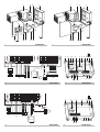
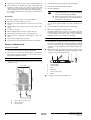
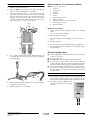
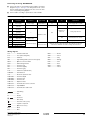
INSTALLATION AND OPERATION MANUAL Option kit for combination of Daikin condensing units with field supplied evaporators EKEXFCBAV3 EKEXDCBAV3 1 2 3 6 5 1 3 6 2 5 1 2 4 7 10 9 11 8 1 7 13 12 9 8 13 2 EKEXFCBAV3 EKEXDCBAV3 4 3 2 expansion valve gas liquid Y1 Y2 Y3 Y4 Y5 Y6 R3 R4 R1 R2 L N Y1 Y2 Y3 Y4 Y5 Y6 H1 H2 remocon outdoor ON/OFF error operation 8 9 5 7 3 5 1 X24A 6 0-10 V P1 P2 F1 F2 T1 T2 C1 C2 C3 C4 C5 C6 R2T N R3T L 4 0 +10 H3 H4 F1 F2 H6 H1 H2 H3 H4 H5 3 H5 H6 4 EKEXFCBAV3 EKEXFCBAV3 5 6 expansion valve L gas liquid air 2 remocon outdoor ON/OFF N Y1 Y2 Y3 Y4 Y5 Y6 R3 R4 R1 R2 R5 R6 P1 P2 F1 F2 T1 T2 4 5 3 1 X24A 10 H8 F2 H1 H2 H3 H4 R1T Y1 Y2 Y3 Y4 Y5 Y6 R2T N R3T F1 L H5 H6 H1 H2 H4 H3 H5 H7 5 EKEXDCBAV3 6 H6 H7 H8 EKEXDCBAV3 CE - DECLARACION-DE-CONFORMIDAD CE - DICHIARAZIONE-DI-CONFORMITA CE - ¢H§ø™H ™YMMOPºø™H™ 09 08 07 06 05 04 03 02 10 under iagttagelse af bestemmelserne i: 11 enligt villkoren i: 12 gitt i henhold til bestemmelsene i: 13 noudattaen määräyksiä: 14 za dodržení ustanovení předpisu: 15 prema odredbama: 16 követi a(z): 17 zgodnie z postanowieniami Dyrektyw: 18 în urma prevederilor: 19 ob upoštevanju določb: 20 vastavalt nõuetele: 21 следвайки клаузите на: 22 laikantis nuostatų, pateikiamų: 23 ievērojot prasības, kas noteiktas: 24 održiavajúc ustanovenia: 25 bunun koşullarına uygun olarak: as set out in the Technical Construction File DAIKIN.TCF.022 and judged positively by TNO according to the Certificate 0305020101. Hinweis * wie in der Technischen Konstruktionsakte DAIKIN.TCF.022 aufgeführt und von TNO positiv ausgezeichnet gemäß Zertifikat 0305020101. Remarque * tel que stipulé dans le Fichier de Construction Technique DAIKIN.TCF.022 et jugé positivement par TNO conformément au Certificat 0305020101. Bemerk * zoals vermeld in het Technisch Constructiedossier DAIKIN.TCF.022 en in orde bevonden door TNO overeenkomstig Certificaat 0305020101. Nota * tal como se expone en el Archivo de Construcción Técnica DAIKIN.TCF.022 y juzgado positivamente por TNO según el Certificado 0305020101. Nota * delineato nel File Tecnico di Costruzione DAIKIN.TCF.022 e giudicato positivamente da TNO secondo il Certificato 0305020101. ™ËÌ›ˆÛË * fiˆ˜ ÚÔÛ‰ÈÔÚ›˙ÂÙ·È ÛÙÔ ∞Ú¯Â›Ô ∆¯ÓÈ΋˜ ∫·Ù·Û΢‹˜ DAIKIN.TCF.022 Î·È ÎÚ›ÓÂÙ·È ıÂÙÈο ·fi ÙÔ TNO Û‡Ìʈӷ Ì ÙÔ ¶ÈÛÙÔÔÈËÙÈÎfi 0305020101. Nota * tal como estabelecido no Ficheiro Técnico de Construção DAIKIN.TCF.022 e com o parecer positivo de TNO de acordo com o Certificado 0305020101. Примечание * как указано в Досье технического толкования DAIKIN.TCF.022 и в соответствии с положительным решением TNO согласно Свидетельству 0305020101. 01 Note * 01 following the provisions of: 02 gemäß den Vorschriften der: 03 conformément aux stipulations des: 04 overeenkomstig de bepalingen van: 05 siguiendo las disposiciones de: 06 secondo le prescrizioni per: 07 Ì ًÚËÛË Ùˆv ‰È·Ù¿Íˆv Ùˆv: 08 de acordo com o previsto em: 09 в соответствии с положениями: EN60335-2-40, 01 are in conformity with the following standard(s) or other normative document(s), provided that these are used in accordance with our instructions: 02 der/den folgenden Norm(en) oder einem anderen Normdokument oder -dokumenten entspricht/entsprechen, unter der Voraussetzung, daß sie gemäß unseren Anweisungen eingesetzt werden: 03 sont conformes à la/aux norme(s) ou autre(s) document(s) normatif(s), pour autant qu'ils soient utilisés conformément à nos instructions: 04 conform de volgende norm(en) of één of meer andere bindende documenten zijn, op voorwaarde dat ze worden gebruikt overeenkomstig onze instructies: 05 están en conformidad con la(s) siguiente(s) norma(s) u otro(s) documento(s) normativo(s), siempre que sean utilizados de acuerdo con nuestras instrucciones: 06 sono conformi al(i) seguente(i) standard(s) o altro(i) documento(i) a carattere normativo, a patto che vengano usati in conformità alle nostre istruzioni: 07 Â›Ó·È Û‡Ìʈӷ Ì ÙÔ(·) ·ÎfiÏÔ˘ıÔ(·) ÚfiÙ˘Ô(·) ‹ ¿ÏÏÔ ¤ÁÁÚ·ÊÔ(·) ηÓÔÓÈÛÌÒÓ, ˘fi ÙËÓ ÚÔ¸fiıÂÛË fiÙÈ ¯ÚËÛÈÌÔÔÈÔ‡ÓÙ·È Û‡Ìʈӷ Ì ÙȘ Ô‰ËÁ›Â˜ Ì·˜: Jiro Tomita Director Quality Assurance Ostend, 15th of June 2006 19 Direktive z vsemi spremembami. 20 Direktiivid koos muudatustega. 21 Директиви, с техните изменения. 22 Direktyvose su papildymais. 23 Direktīvās un to papildinājumos. 24 Smernice, v platnom znení. 25 Değiştirilmiş halleriyle Yönetmelikler. Zandvoordestraat 300, B-8400 Oostende, Belgium 25 24 23 22 21 10 Direktiver, med senere ændringer. 11 Direktiv, med företagna ändringar. 12 Direktiver, med foretatte endringer. 13 Direktiivejä, sellaisina kuin ne ovat muutettuina. 14 v platném znění. 15 Smjernice, kako je izmijenjeno. 16 irányelv(ek) és módosításaik rendelkezéseit. 17 z późniejszymi poprawkami. 18 Directivelor, cu amendamentele respective. kot je določeno v tehnični mapi DAIKIN.TCF.022 in odobreno s strani TNO v skladu s certifikatom 0305020101. nagu on näidatud tehnilises dokumentatsioonis DAIKIN.TCF.022 ja heaks kiidetud TNO järgi vastavalt sertifikaadile 0305020101. Забележка * както е заложено в Акта за техническа конструкция DAIKIN.TCF.022 и оценено положително от TNO съгласно Сертификат 0305020101. Pastaba * kaip nurodyta Techninėje konstrukcijos byloje DAIKIN.TCF.022 ir patvirtinta TNO pagal pažymėjimą 0305020101. Piezīmes * kā noteikts tehniskajā dokumentācijā DAIKIN.TCF.022, atbilstoši TNO pozitīvajam lēmumam ko apliecina sertifikāts 0305020101. Poznámka * ako je to stanovené v Súbore technickej konštrukcie DAIKIN.TCF.022 a kladne posúdené TNO podľa Certifikátu 0305020101. Not * DAIKIN.TCF.022 Teknik Yapı Dosyasında belirtildiği gibi ve 0305020101 sertifikasına göre TNO tarafından olumlu olarak değerlendirilmiştir. 19 Opomba * 20 Märkus * 01 Directives, as amended. 02 Direktiven, gemäß Änderung. 03 Directives, telles que modifiées. 04 Richtlijnen, zoals geamendeerd. 05 Directivas, según lo enmendado. 06 Direttive, come da modifica. 07 √‰ËÁÈÒv, fiˆ˜ ¤¯Ô˘Ó ÙÚÔÔÔÈËı›. 08 Directivas, conforme alteração em. 09 Директив со всеми поправками. som anført i den Tekniske Konstruktionsfil DAIKIN.TCF.022 og positivt vurderet af TNO i henhold til Certifikat 0305020101. 11 Information * utrustningen är utförd i enlighet med den Tekniska Konstruktionsfilen DAIKIN.TCF.022 som positivt intygas av TNO vilket också framgår av Certifikat 0305020101. 12 Merk * som det fremkommer i den Tekniske Konstruksjonsfilen DAIKIN.TCF.022 og gjennom positiv bedømmelse av TNO ifølge Sertifikat 0305020101. 13 Huom * jotka on esitetty Teknisessä Asiakirjassa DAIKIN.TCF.022 ja jotka TNO on hyväksynyt Sertifikaatin 0305020101 mukaisesti. 14 Poznámka * jak bylo uvedeno v souboru technické konstrukce DAIKIN.TCF.022 a pozitivně zjištěno TNO v souladu s osvědčením 0305020101. 15 Napomena * kako je izloženo u Datoteci o tehničkoj konstrukciji DAIKIN.TCF.022 i pozitivno ocijenjeno od strane TNO prema Certifikatu 0305020101. 16 Megjegyzés * a(z) DAIKIN.TCF.022 műszaki konstrukciós dokumentáció alapján, a(z) TNO igazolta a megfelelést a(z) 0305020101 tanúsítvány szerint. 17 Uwaga * zgodnie z archiwalną dokumentacją konstrukcyjną DAIKIN.TCF.022, pozytywną opinią TNO i Świadectwem 0305020101. 18 Notă * conform celor stabilite în Dosarul tehnic de construcţie DAIKIN.TCF.022 şi apreciate pozitiv de TNO în conformitate cu Certificatul 0305020101. 10 Bemærk * Low Voltage 73/23/EEC Machinery Safety 98/37/EEC Electromagnetic Compatibility 89/336/EEC * CE - ATITIKTIES-DEKLARACIJA CE - ATBILSTĪBAS-DEKLARĀCIJA CE - VYHLÁSENIE-ZHODY CE - UYUMLULUK-BİLDİRİSİ z vso odgovornostjo izjavlja, da je oprema klimatskih naprav, na katero se izjava nanaša: kinnitab oma täielikul vastutusel, et käesoleva deklaratsiooni alla kuuluv kliimaseadmete varustus: декларира на своя отговорност, че оборудването за климатична инсталация, за което се отнася тази декларация: visiška savo atsakomybe skelbia, kad oro kondicionavimo įranga, kuriai taikoma ši deklaracija: ar pilnu atbildību apliecina, ka tālāk uzskaitītās gaisa kondicionēšanas iekārtas, uz kuriem attiecas šī deklarācija: vyhlasuje na vlastnú zodpovednosť, že klimatizačné zariadenie, na ktoré sa vzťahuje toto vyhlásenie: tamamen kendi sorumluluğunda olmak üzere bu bildirinin ilgili olduğu klima donanımının aşağıdaki gibi olduğunu beyan eder: CE - IZJAVA O SKLADNOSTI CE - VASTAVUSDEKLARATSIOON CE - ДЕКЛАРАЦИЯ-ЗА-СЪОТВЕТСТВИЕ 16 megfelelnek az alábbi szabvány(ok)nak vagy egyéb irányadó dokumentum(ok)nak, ha azokat előírás szerint használják: 17 spełniają wymogi następujących norm i innych dokumentów normalizacyjnych, pod warunkiem że używane są zgodnie z naszymi instrukcjami: 18 sunt în conformitate cu următorul (următoarele) standard(e) sau alt(e) document(e) normativ(e), cu condiţia ca acestea să fie utilizate în conformitate cu instrucţiunile noastre 19 skladni z naslednjimi standardi in drugimi normativi, pod pogojem, da se uporabljajo v skladu z našimi navodili: 20 on vastavuses järgmis(t)e standardi(te)ga või teiste normatiivsete dokumentidega, kui neid kasutatakse vastavalt meie juhenditele: 21 съответстват на следните стандарти или други нормативни документи, при условие, че се използват съгласно нашите инструкции: 22 atitinka žemiau nurodytus standartus ir (arba) kitus norminius dokumentus su sąlyga, kad yra naudojami pagal mūsų nurodymus: 23 tad, ja lietoti atbilstoši ražotāja norādījumiem, atbilst sekojošiem standartiem un citiem normatīviem dokumentiem: 24 sú v zhode s nasledovnou(ými) normou(ami) alebo iným(i) normatívnym(i) dokumentom(ami), za predpokladu, že sa používajú v súlade s našim návodom: 25 ürünün, talimatlarımıza göre kullanılması koşuluyla aşağıdaki standartlar ve norm belirten belgelerle uyumludur: 19 20 21 22 23 24 25 CE - IZJAVA-O-USKLAĐENOSTI CE - MEGFELELŐSÉGI-NYILATKOZAT CE - DEKLARACJA-ZGODNOŚCI CE - DECLARAŢIE-DE-CONFORMITATE erklærer under eneansvar, at udstyret til klimaregulering, som denne deklaration vedrører: deklarerer i egenskap av huvudansvarig, att luftkonditioneringsutrustningen som berörs av denna deklaration innebär att: erklærer et fullstendig ansvar for at det luftkondisjoneringsutstyr som berøres av denne deklarasjon, innebærer at: iilmoittaa yksinomaan omalla vastuullaan, että tämän ilmoituksen tarkoittamat ilmastointilaitteet: prohlašuje ve své plné odpovědnosti, že klimatizační zařízení, k nimž se toto prohlášení vztahuje: izjavljuje pod isključivo vlastitom odgovornošću da oprema za klimatizaciju na koju se ova izjava odnosi: teljes felelőssége tudatában kijelenti, hogy a klímaberendezések, melyekre e nyilatkozat vonatkozik: deklaruje na własną i wyłączną odpowiedzialność, że klimatyzatory, których dotyczy niniejsza deklaracja: declară pe proprie răspundere că echipamentele de aer condiţionat la care se referă această declaraţie: CE - ERKLÆRING OM-SAMSVAR CE - ILMOITUS-YHDENMUKAISUUDESTA CE - PROHLÁŠENÍ-O-SHODĚ 08 estão em conformidade com a(s) seguinte(s) norma(s) ou outro(s) documento(s) normativo(s), desde que estes sejam utilizados de acordo com as nossas instruções: 09 соответствуют следующим стандартам или другим нормативным документам, при условии их использования согласно нашим инструкциям: 10 overholder følgende standard(er) eller andet/andre retningsgivende dokument(er), forudsat at disse anvendes i henhold til vore instrukser: 11 respektive utrustning är utförd i överensstämmelse med och följer följande standard(er) eller andra normgivande dokument, under förutsättning att användning sker i överensstämmelse med våra instruktioner: 12 respektive utstyr er i overensstemmelse med følgende standard(er) eller andre normgivende dokument(er), under forutssetning av at disse brukes i henhold til våre instrukser: 13 vastaavat seuraavien standardien ja muiden ohjeellisten dokumenttien vaatimuksia edellyttäen, että niitä käytetään ohjeidemme mukaisesti: 14 za předpokladu, že jsou využívány v souladu s našimi pokyny, odpovídají následujícím normám nebo normativním dokumentům: 15 u skladu sa slijedećim standardom(ima) ili drugim normativnim dokumentom(ima), uz uvjet da se oni koriste u skladu s našim uputama: 10 11 12 13 14 15 16 17 18 CE - DECLARAÇÃO-DE-CONFORMIDADE СЕ - ЗАЯВЛЕНИЕ-О-СООТВЕТСТВИИ CE - OPFYLDELSESERKLÆRING CE - FÖRSÄKRAN-OM-ÖVERENSTÄMMELSE declares under its sole responsibility that the air conditioning equipment to which this declaration relates: erklärt auf seine alleinige Verantwortung dass die Ausrüstung der Klimageräte für die diese Erklärung bestimmt ist: déclare sous sa seule responsabilité que l'équipement d'air conditionné visés par la présente déclar ation: verklaart hierbij op eigen exclusieve verantwoordelijkheid dat de airconditioningapparatuur waarop deze verklaring betrekking heeft: declara bajo su única responsabilidad que el equipo de aire acondicionado al que hace referencia la declaración: dichiara sotto la propria responsabilità che gli apparecchi di condizionamento a cui è riferita questa dichiarazione: ‰ËÏÒÓÂÈ Ì ·ÔÎÏÂÈÛÙÈ΋ Ù˘ ¢ı‡ÓË fiÙÈ Ô ÂÍÔÏÈÛÌfi˜ ÙˆÓ ÎÏÈÌ·ÙÈÛÙÈÎÒÓ Û˘Û΢ÒÓ ÛÙ· ÔÔ›· ·Ó·Ê¤ÚÂÙ·È Ë ·ÚÔ‡Û· ‰‹ÏˆÛË: declara sob sua exclusiva responsabilidade que os equipamentos de ar condicionado a que esta declaração se refere: заявляет, исключительно под свою ответственность, что оборудование для кондиционирования воздуха, к которому относится настоящее заявление: EKEXDCBAV3, EKEXFCBAV3, 01 02 03 04 05 06 07 08 09 Daikin Europe N.V. CE - DECLARATION-OF-CONFORMITY CE - KONFORMITÄTSERKLÄRUNG CE - DECLARATION-DE-CONFORMITE CE - CONFORMITEITSVERKLARING 3PW26871-2A EKEXFCBAV3 EKEXDCBAV3 CONTENTS Installation and operation manual Option kit for combination of Daikin condensing units with field supplied evaporators Page Introduction ............................................................... 1 We distinguish 2 different control boxes, each with its own application and installation requirements. ■ ■ Operation with 0–10 V input to control the capacity An external controller is needed to control the capacity. For details of the necessary functions of the external controller refer to paragraph "Operation with 0–10 V capacity control" on page 8. It can be used to control the room temperature or air discharge temperature. Installation ................................................................. 1 Accessories....................................................................................... 1 Name and function of parts ............................................................... 2 Before installation.............................................................................. 2 ■ Operation with fixed Te temperature control This system operates on a fixed evaporating temperature. Selecting the installation site............................................................. 2 Valve kit installation ........................................................................... 3 Installation of the electrical control box ............................................. 4 Electric wiring work ........................................................................... 4 EKEXFCB control box (2 possible operation modes) ■ EKEXDCB control box The system will operate as a standard indoor unit to control the room temperature. This system does not require a specific external controller. Installation of thermistors .................................................................. 7 Refrigerant piping work ..................................................................... 8 Test operation.................................................................................... 8 INSTALLATION Operation and maintenance ..................................... 8 ACCESSORIES What to do before operation.............................................................. 8 Operation and display signals ........................................................... 9 EKEXFCB EKEXDCB — 1 Troubleshooting ................................................................................. 9 Thermistor (R1T) Maintenance.................................................................................... 10 Thermistor (R3T/R2T) (2.5 m cable) 2 Insulation sheet 2 Rubber sheet 2 Disposal requirements .................................................................... 10 READ THESE INSTRUCTIONS CAREFULLY BEFORE INSTALLATION AND OPERATION. IMPROPER INSTALLATION OR ATTACHMENT OF EQUIPMENT OR ACCESSORIES COULD RESULT IN ELECTRIC SHOCK, SHORT-CIRCUIT, LEAKS, FIRE OR OTHER DAMAGE TO THE EQUIPMENT. BE SURE ONLY TO USE ACCESSORIES MADE BY DAIKIN WHICH ARE SPECIFICALLY DESIGNED FOR USE WITH THE EQUIPMENT AND HAVE THEM INSTALLED BY A PROFESSIONAL. IF UNSURE OF INSTALLATION PROCEDURES OR USE, ALWAYS CONTACT YOUR DAIKIN DEALER FOR ADVICE AND INFORMATION. Wire to wire splice 4 6 Installation and operation manual 1 Screw nut 6 8 Tie wrap 6 Capacity setting adaptor 7 Stopper (closing cup) 2 — Obligatory accessory INTRODUCTION EKEXFCB ■ ■ Do only use this system in combination with a field supplied air handling unit. Do not connect this system to other indoor units. Only optional controls as listed in the optional accessories list can be used. Expansion valve kit EKEXDCB EKEXV Refer to chapter "Valve kit installation" on page 3 for installation instructions. Optional accessories Remote controller EKEXFCB EKEXDCB 1(*) 1 (*) Not required for operation, only useful accessory tool for service and installation. Installation and operation manual 1 EKEXFCBAV3 + EKEXDCBAV3 Option kit for combination of Daikin condensing units with field supplied evaporators 4PW30903-1 NAME AND FUNCTION OF PARTS (See figure 1 and NOTE figure 2) Parts and components 1 Outdoor unit 2 Control box (EKEXFCB / EKEXDCB) 3 Air handling unit (field supply) 4 Controller (field supply) 5 Field piping (field supply) 6 Expansion valve kit ■ If conflicting result, volume selection has priority over capacity. ■ The expansion valve is an electronic type, it is controlled by the thermistors that are added in the circuit. Each expansion valve can control a range of evaporators (air handling units) sizes. ■ The selected evaporator designed for R410A. ■ Extraneous substances (including mineral oils or moisture) must be prevented from getting mixed into the system. ■ SST: saturated suction temperature at exit of evaporator. Wiring connections 7 Outdoor unit power supply 8 Control box wiring (Power supply and communication between control box and outdoor unit) 9 Evaporator thermistors 10 Communication between controller and control box 11 Power supply and control wiring for evarporator (air handling unit) and controller (power supply is separate from the outdoor unit) 12 Air thermistor control for evaporator (air handling unit) 13 Remote controller ( BEFORE 3 ■ Connect the correct selected capacity setting adaptor to X24A (A1P). (See figure 4 and figure 6) EKEXV kit INSTALLATION See table below for applicable units. Select the evaporator (field supply) according to the technical data and limitations mentioned below. Lifetime of the outdoor unit, operation range or operation reliability may be influenced if you neglect these limitations. Limits for outdoor unit (expansion valve kit) Outdoor unit (class) EKEXV63~125 200 EKEXV100~250 125 EKEXV63~140 250 EKEXV125~250 140 EKEXV80~140 Allowed heat exchanger capacity (kW) Minimum Maximum Minimum Maximum 63 0.96 1.22 6.4 7.8 80 1.22 1.53 8.1 9.9 100 1.53 1.91 10.1 12.3 125 1.91 2.14 12.6 15.4 140 2.14 2.67 14.4 17.6 200 3.06 3.82 20.2 24.6 250 3.82 4.78 25.2 30.8 Saturated suction temperature (SST) = 6°C, SH (superheat) = 5 K, air temperature = 27°C DB / 19°C WB. 1 Selecting the condensing unit Depending on necessary capacity of the combination an outdoor unit needs to be selected (see "Engineering databook" for capacity). ■ Each outdoor unit can be connected to a range of evaporators (air handling units). ■ The range is determined by the allowed expansion valve kits. 2 EKEXV kit Capacity setting adaptor label (indication) 63 J71 140 J160 80 J90 200 J224 100 J112 250 J280 125 J140 Tick ✓ when checked Depending on the heat exchanger, a connectable EKEXV (expansion valve kit) must be selected to these limitations. EKEXV class Capacity setting adaptor label (indication) For the following items, take special care during construction and check after installation is finished ■ Are the thermistors fixed firmly? Thermistor may come loose. ■ Is the freeze-up setting done correctly? The evaporator (air handling unit) may freeze up. ■ Is the control box fixed firmly? The unit may drop, vibrate or make noise. ■ Do electrical connections comply with specifications? The unit may malfunction or components may burn out. ■ Are wiring and piping correct? The unit may malfunction or components may burn out. ■ Is the unit safely grounded? Dangerous at electric leakage. EKEXV kit 100 Allowed heat exchanger volume (dm3) be ■ The corresponding capacity setting adaptor needs to be selected depending on the expansion valve. = for service only) EKEXV kit must Selecting the capacity setting adaptor (see accessories) Cautions for selection of the evaporator (air handling unit) Outdoor unit (class) unit Compliance to directive 97/23/EEC (Pressure Equipment Directive): only connect an evaporator of category I or less. SELECTING THE INSTALLATION SITE This is a class A product. In a domestic environment this product may cause radio interference in which case the user may be required to take adequate measures. Select an installation site where the following conditions are fulfilled and that meets your customer's approval. ■ The option boxes (expansion valve and electrical control box) can be installed inside and outside). ■ Do not install the option boxes in or on the outdoor unit. ■ Do not put the option boxes in direct sunlight. Direct sunlight will increase the temperature inside the option boxes and may reduce its lifetime and influence its operation. ■ Choose a flat and strong mounting surface. Selecting the expansion valve The corresponding expansion valve needs to be selected for your evaporator. Select the expansion valve according to the above limitations. EKEXFCBAV3 + EKEXDCBAV3 Option kit for combination of Daikin condensing units with field supplied evaporators 4PW30903-1 Installation and operation manual 2 ■ Keep the space in front of the boxes free for future maintenance. 4 Remove the pipe fixing clamp (C) by unscrewing 2x M5. ■ Keep evaporator (air handling unit), power supply wiring and transmission wiring at least 1 m away from televisions and radios. This is to prevent image interference and noise in those electrical appliances. (Noise may be generated depending on the conditions under which the electric wave is generated, even if 1 m is kept.) 5 Remove the upper and lower pipe insulations. 6 Braze the field piping. Precautions ■ Make sure to cool the filters and valve body with a wet cloth and make sure the body temperature does not exceed 120°C during brazing. ■ Make sure that the other parts such as electrical box, tie wraps and wires are protected from direct brazing flames during brazing. Do not install or operate the unit in rooms mentioned below. ■ Where mineral oil, like cutting oil is present. ■ Where the air contains high levels of salt such as air near the ocean. ■ 7 After brazing, put the lower pipe insulation back in place and close it with the upper insulation cover (after pealing off the liner). Where sulphurous gas is present such as that in areas of hot spring. 8 Secure the pipe fixing clamp (C) in place again (2x M5). ■ In vehicles or vessels. 9 Make sure that field pipes are fully insulated. ■ Where voltage fluctuates a lot such as that in factories. ■ Where high concentration of vapor or spray are present. ■ Where machines present. ■ Where acidic or alkaline vapor is present. Cautions for brazing ■ The option boxes must be installed with entrances downward. ■ Be sure to carry out a nitrogen blow when brazing. Brazing without carrying out nitrogen replacement or releasing nitrogen into the piping will create large quantities of oxidized film on the inside of the pipes, adversely affecting valves and compressors in the refrigerating system and preventing normal operation. ■ When brazing while inserting nitrogen into the piping, nitrogen must be set to 0.02 MPa with a pressure-reducing valve (=just enough so that it can be felt on the skin). VALVE generating electromagnetic waves Field pipe insulation must reach up to the insulation you have put back in place as per procedure step 7. Make sure that there is no gap between both ends in order to avoid condensation dripping (finish the connection with tape eventually). are KIT INSTALLATION Mechanical installation 1 Remove the valve kit box cover by unscrewing 4x M5. 2 Drill 4 holes on correct position (measurements as indicated in figure below) and fix the valve kit box securely with 4 screws through the provided holes Ø9 mm. 1 2 3 4 5 Brazing work 3 6 Prepare the inlet/outlet field piping just in front of the connection (do not braze yet). 192.5 mm ■ 1 Refrigerant piping 2 Part to be brazed 3 Taping 4 Hands valve 5 Pressure-reducing valve 6 Nitrogen 6 For details, see manual of the outdoor unit. 340 mm C B A Inlet coming from the outdoor unit B Outlet to evaporator C Pipe fixing clamp Installation and operation manual 3 A EKEXFCBAV3 + EKEXDCBAV3 Option kit for combination of Daikin condensing units with field supplied evaporators 4PW30903-1 INSTALLATION OF THE ELECTRICAL CONTROL BOX (See figure 4 and figure 6) Electrical work 1 Open the electrical box cover (A). 2 Push out ONLY the second lower wire intake hole (B) from inside to outside. Do not damage the membrane. 3 Pass valve cable (with wires Y1 ... Y6) from the control box through that membrane wire intake hole and connect the cable wires into the terminal connector (C) following instructions as described in step 4. Route the cable out of the valve kit box according to figure below and fix with the tie wrap (D). See "Electric wiring work" on page 4 for more details. AC B D 1 Control box 2 Hanger brackets 3 Main PCB 4 Transformer 5 Terminal 6 PCB (for voltage conversion) 7 PCB (power supply) 8 Magnetic relay (operation / compressor ON/OFF) 9 Magnetic relay (error status) 10 Optional PCB (KRP4) Mechanical installation 1 Fix the control box with its hanger brackets to the mounting surface. Use 4 screws (for holes of Ø6 mm). 2 Open the lid of the control box. 3 For electrical wiring: refer to paragraph "Electric wiring work" on page 4. 4 Install the screw nuts. 5 Close the unnecessary openings with stoppers (closing cups). 6 Close the lid securely after installation to ensure that the control box is watertight. ELECTRIC 4 Use a small screwdriver and follow indicated instructions for connecting cable wires into the terminal connector according to the wiring diagram. 3 1 WIRING WORK ■ All field supplied parts and materials and electric works must be conform to local codes. ■ Use copper wire only. ■ All wiring must be performed by an authorized electrician. ■ A main switch or other means for disconnection, having a contact separation in all poles, must be incorporated in the fixed wiring in accordance with relevant local and national legislation. ■ Refer to the installation manual attached to the outdoor unit for the size of power supply electric wire connected to the outdoor unit, the capacity of the circuit breaker and switch, wiring and wiring instructions. Connection of the wires inside the control box 4 For connection to outdoor unit and to controller (field supply): Pull the wires inside through the screw nut and close the nut firmly in order to ensure a good pull relieve and water protection. 2 The cables require an additional pullrelief. Strap the cable with the installed tie wrap. 2 1 5 Make sure that field wiring and insulation is not squeezed when closing the valve kit box cover. 6 Close the valve kit box cover (4x M5). EKEXFCBAV3 + EKEXDCBAV3 Option kit for combination of Daikin condensing units with field supplied evaporators 4PW30903-1 Installation and operation manual 4 Precautions Connecting the wiring: EKEXFCBAV3 ■ Thermistor cable and remote controller wire should be located at least 50 mm away from power supply wires and from wires to the controller. Not following this guideline may result in malfunction due to electrical noise. ■ Connect the wires to the terminal board according to the wiring diagram in figure 3. See figure 4 for wiring intake in the control box. The wiring intake hole indication H1 refers to the H1 cable of the corresponding wiring diagram. ■ Use only specified wires, and tightly connect wires to the terminals. Keep wiring in neat order so that it does not obstruct other equipment. Incomplete connections could result in overheating, and in worse case electric shock or fire. ■ Connect cables according to specifications of the next table. Take special precaution for connection to the controller (field supply). Do not miswire the output signals (operation or error) nor the input signal (ON/OFF). This mistake could damage the entire system. Table connection and application Description Connect to Type of cable Cross section (mm2)(*) Maximum length (m) Specifications L, N, earth Power supply Power supply H05VV-F3G2.5 2.5 — Power supply 230 V 1~50 Hz Y1~Y6 Expansion valve connection Expansion valve kit LIYCY3 x 2 x 0.75 20 Digital output 12 V DC R1,R2 Thermistor R2T (liquid pipe) Standard 2.5 Maximum 20 Analog input 16 V DC R3,R4 Thermistor R3T (gas pipe) P1,P2 Remote controller (optional) 100 Communication line 16 V DC F1,F2 Communication to outdoor unit T1,T2 ON/OFF C1,C2 Error signal C3,C4 Operation signal(‡) C5,C6 Capacity step(**) (*) (†) (‡) (**) — H05VV-F2 x 0.75 0.75 Outdoor unit Digital input 16 V DC Controller field supply Digital output: voltage free. Maximum 230 V, maximum 0,5 A (†) LIYCY4 x 2 x 0.75 Analog input: 0–10 V Recommended size (all wiring must comply with local codes). The maximum length depends on the external device that is connected (controller/relay,....) Operation signal: indicates compressor operation. Only necessary for capacity controlled system. Wiring diagram A1P ....................Printed circuit board ........... Field wiring A2P ....................Printed circuit board (for voltage conversion) L......................... Live A3P ....................Printed circuit board (power supply) N ........................ Neutral F1U ....................Fuse (250 V, F5A)(A1P) F2U ....................Fuse (250 V, T1A)(A3P) F3U ....................Field fuse HAP....................Light emitting diode (service monitor-green) K1R ....................Magnetic relay (operation / compressor ON/OFF) K2R ....................Magnetic relay (error status) KAR, KPR ..........Magnetic relay Q1DI...................Earth leakage breaker R2T ....................Thermistor (liquid) R3T ....................Thermistor (gas) T1R ....................Transformer (220 V/21.8 V) X1M,X2M,X3M ...Terminal block Y1E ....................Electronic expansion valve X1M-R1/R2 ........Thermistor liquid X1M-R3/R4 ........Thermistor gas , ......... Connector ......................... Wire clamp ..................... Protective earth (screw) ............... Separate component ............... Optional accessory BLK.................... Black BLU.................... Blue BRN ................... Brown GRN................... Green GRY ................... Gray ORG .................. Orange PNK ................... Pink RED ................... Red WHT .................. White YLW ................... Yellow X1M-Y1~6 ..........Expansion valve X2M-P1/P2.........Communication remote controller X2M-C1/C2 ........Output: error status X2M-C3/C4 ........Output: operation / compressor ON/OFF X2M-T1/T2 .........Input: ON/OFF X2M-F1/F2 .........Communication outdoor unit X2M-C5/C6 ........Input: 0–10 V DC capacity control Installation and operation manual 5 EKEXFCBAV3 + EKEXDCBAV3 Option kit for combination of Daikin condensing units with field supplied evaporators 4PW30903-1 Connecting the wiring: EKEXDCBAV3 ■ Connect the wires to the terminal board according to the wiring diagram in figure 5. See figure 6 for wiring intake in the control box. The wiring intake hole indication H1 refers to the H1 cable of the corresponding wiring diagram. ■ Connect cables according to specifications of the next table. Table connection and application Description Connect to Type of cable Cross section (mm2)(*) Maximum length (m) Specifications L, N, earth Power supply Power supply H05VV-F3G2.5 2.5 — Power supply 230 V 1~50 Hz Y1~Y6 Expansion valve connection Expansion valve kit LIYCY3 x 2 x 0.75 20 Digital output 12 V DC R1,R2 Thermistor R2T (liquid pipe) R3,R4 Thermistor R3T (gas pipe) Standard: 2.5 Max.: 20 Analog input 16 V DC 100 Communication line 16 V DC — Digital input 16 V DC R5,R6 Thermistor R1T (air) P1,P2 Remote controller F1,F2 Communication to outdoor unit T1,T2 ON/OFF — Capacity step — Error signal — Operation signal — 0.75 H05VV-F2 x 0.75 Outdoor unit Controller field supply LIYCY4 x 2 x 0.75 Optional connection: when the function of the switch box needs to be extended: see KRP4A51 for details of settings and instructions. (*) Recommended size (all wiring must comply with local codes). Wiring diagram A1P.................... Printed circuit board BRN ................... Brown F1U.................... Fuse (250 V, F5A)(A1P) GRN ................... Green F3U.................... Field fuse GRY ................... Gray HAP ................... Light emitting diode (service monitor-green) ORG................... Orange KRP4 ................. Optional connection PCB PNK.................... Pink Q1DI .................. Earth leakage breaker RED ................... Red R1T.................... Thermistor (air) WHT................... White R2T.................... Thermistor (liquid) YLW ................... Yellow R3T.................... Thermistor (gas) T1R.................... Transformer (220 V/21.8 V) X1M,X3M........... Terminal block Y1E.................... Electronic expansion valve X1M-R1/R2........ Thermistor liquid X1M-R3/R4........ Thermistor gas X1M-R5/R6........ Thermistor air X1M-Y1~6 ......... Expansion valve X1M-P1/P2 ........ Communication remote controller X1M-T1/T2......... Input: ON/OFF X1M-F1/F2......... Communication outdoor unit ........... Field wiring L......................... Live N ........................ Neutral , ......... Connector ........................ Wire clamp ..................... Protective earth (screw) ............... Separate component ............... Optional accessory BLK.................... Black BLU.................... Blue EKEXFCBAV3 + EKEXDCBAV3 Option kit for combination of Daikin condensing units with field supplied evaporators 4PW30903-1 Installation and operation manual 6 INSTALLATION Fixation of the thermistor OF THERMISTORS Refrigerant thermistors ■ Put the thermistor wire slightly down to avoid water accumulation on top of the thermistor. ■ Make good contact between thermistor and evaporator. Put the top of the thermistors on the evaporator, this is the most sensitive point of the thermistor. Location of the thermistor A correct installation of the thermistors is required to ensure a good operation: 1. Liquid (R2T) Install the thermistor behind the distributor on the coldest pass of the heat exchanger (contact your heat exchanger dealer). 2. Gas (R3T) Install the thermistor at the outlet of the heat exchanger as close as possible to the heat exchanger. 12 Evaluation must be done to check if the evaporator is protected against freeze-up. Execute test operation and check for freeze-up. 45 ° 1 Most sensitive point of the thermistor 2 Maximize the contact 1 Fix the thermistor with insulating aluminum tape (field supply) in order to ensure a good heat transference. 2 Put the supplied piece of rubber around the thermistor (R2T/R3T) in order to avoid loosening of the thermistor after some years. 3 Fasten the thermistor with 2 tie wraps. 4 Insulate the thermistor with the supplied insulation sheet. 1 2 1 Liquid R2T 2 Gas R3T Installation of the thermistor cable 1 Put the thermistor cable in a separate protective tube. 2 Always add a pull-relief to the thermistor cable to avoid strain on the thermistor cable and loosening of the thermistor. Strain on the thermistor cable or loosening of the thermistor may result in bad contact and incorrect temperature measurement. 1 2 45 ° Air thermistor (only for EKEXDCB) The air thermistor (R1T) can be installed either in the room that needs temperature control or in the suction area of the evaporator. NOTE Installation and operation manual 7 For room temperature control the delivered thermistor (R1T) can be replaced by an optional remote sensor kit KRCS01-1(A) (to be ordered separately). EKEXFCBAV3 + EKEXDCBAV3 Option kit for combination of Daikin condensing units with field supplied evaporators 4PW30903-1 Installation of longer thermistor cable (R1T/R2T/R3T) ■ In case of poor distribution in the evaporator, 1 or more passes of the evaporator may freeze-up (collect ice) ➞ put the thermistor (R2T) on this position. ■ Make sure that the evaporator fan keeps operating, even when the outdoor unit compressor stopped operating (only at the moment of "anti-freeze-up" control). ■ Depending on operation conditions (e.g.: outdoor ambient temperature) it is possible that the settings must be changed after commissioning. The thermistor is supplied with a standard cable of 2.5 m. This cable can be made longer to up to 20 m. Install the longer thermistor cable with the delivered wire to wire splices 1 Cut the wire or bundle the remainder of the thermistor cable. Keep at least 1 m of the original thermistor cable. Do not bundle the cable inside the control box. 2 Strip the wire ±7 mm at both ends and insert these ends into the wire to wire splice. 3 Pinch the splice with the correct crimp tool (pliers). 4 After connection, heat up the shrink-insulation of the wire to wire splice with a shrink-heater to make a water tight connection. 5 Wrap electrical insulation tape around the connection. 6 Put a pull-relief in front of and behind the connection. OPERATION WHAT AND MAINTENANCE TO DO BEFORE OPERATION ■ Before initiating operation, contact your dealer to get the operation manual that corresponds to your system. ■ The connection must be made on an accessible location. ■ ■ To make the connection waterproof, the connection can also be made in a switch box or connector box. Refer to the dedicated manual of the controller (field supply) and evaporator (field supply). ■ ■ The thermistor cable should be located at least 50 mm away from power supply wire. Not following this guideline may result in malfunction due to electrical noise. Make sure that the air handling unit fan is ON when the outdoor unit is operating. REFRIGERANT PIPING WORK Field settings for EKEXDCB Refer to the installation manuals of both the outdoor unit and the remote controller. Field settings for EKEXFCB All field piping must be provided by a licensed refrigeration technician and must comply with the relevant local and national codes. ■ For refrigerant piping of outdoor unit, refer to the installation manual supplied with the outdoor unit. ■ Follow the outdoor unit specifications for additional charging, piping diameter and installation. ■ The maximum allowed piping length depends on the connected outdoor model. When changing the settings: 1. Make the required settings. 2. Turn power OFF. 3. Remove the remote controller after servicing and checking the system in cooling mode. Operating the remote controller may disturb the normal operation of the system. 4. Do not change T1/T2 operation signal during power failure. 5. Put power of indoor and outdoor unit ON. Setting the temperature control system TEST OPERATION Mode No. Before executing "test operation" as well as before operating the unit, you must check the following: ■ Put the evaporator fan on minimum airflow. ■ Refer to the section of "For the following items, take special care during construction and check after installation is finished" on page 2. ■ After finishing the construction of refrigerant piping, drain piping and electric wiring, conduct test operation accordingly to protect the unit. ■ Open the gas side stop valve. ■ Open the liquid side stop valve. Code No. Description of setting 01 Operation with 0–10 V capacity control (= factory setting) 02 Operation with fixed Te temperature control 13(23)–0 or SST = evaporating temperature or saturated suction temperature. Te Operation with 0–10 V capacity control The 0–10 V input is only used for this system of operation and is the base of the capacity control. Executing the test operation This system needs a field supplied controller with a temperature sensor. The temperature sensor can be used to control any temperature: 1. Start the evaporator fan operation. ■ Suction air of the evaporator 2. Close the contact T1/T2 (ON/OFF). ■ Room air 3. Confirm function of the unit according to the manual and check if the evaporator has collected ice (freeze-up). ■ Discharge air of the evaporator ■ If the unit collects ice: see "Troubleshooting" on page 9. EKEXFCBAV3 + EKEXDCBAV3 Option kit for combination of Daikin condensing units with field supplied evaporators 4PW30903-1 Installation and operation manual 8 Program the field supplied controller to generate a 0–10 V signal within conditions as listed. Also refer to the graphic and further data in this paragraph for more details. ■ When target temperature is reached: 5 V ■ When more capacity is needed: 5–10 V ■ When less capacity is needed: 0–5 V OPERATION AND DISPLAY SIGNALS Error: open C1/C2 error signal Output °C Power failure Normal operation No error: closed (relay activated) T1/T2 is open: no error detection anymore C3/C4 operation signal +∆Tmax C5/C6: capacity step ∆T=0 Abnormal operation on condenser or control system Open Compressor operating 0–10 V Only necessary for field setting 13(23)–0 = 01 0–10 V capacity control(*) Input T1/T2 operation input(†) Compressor not operating Closed Open Closed No cooling requested Cooling requested (*) Refer to paragraph "Operation with 0–10 V capacity control" on page 8. (†) See field setting 12(22)–5. –∆Tmax 0 A 5 10 V A ■ The fan of the evaporator must operate before cooling operation is required to the outdoor unit. ■ When the operation signal is activated, the evaporator and fan must operate. Failure to this will cause a safety to operate or freezing up of the evaporator (air handling unit). Controller voltage output to EKEXFCB Capacity increase area Capacity decrease area Voltage output = linear function with ∆T ∆T = [actual measured temperature] – [target temperature] When ∆T=0, the target temperature is reached. ∆Tmax = maximum temperature variation as defined by installation Recommended value for ∆Tmax=[1°C~5°C]. ∆T (°C) Voltage output from controller (field supply) –∆Tmax 0 +∆Tmax 0V 5V 10 V TROUBLESHOOTING To set up the system and make trouble shooting possible, it is required to connect the remote controller to the option kit. Not a malfunction of the air conditioner The system does not operate Operation with fixed Te temperature control ■ The system does not restart immediately after the cooling is requested. If the operation lamp lights, the system is in normal operating condition. It does not restart immediately because one of its safety devices actuates to prevent the system from being overloaded. The system will turn on again automatically after 3 minutes. ■ The system does not restart immediately after the power supply is turned on. Wait 1 minute until the micro computer is prepared for operation. The evaporating temperature (Te) at which the application has to operate can be set by code numbers as listed below. Mode No. Code No. Description of setting(*) 01 Te = 3°C 02 Te = 4°C 03 Te = 5°C 04 Te = 6°C (factory setting) 05 Te = 7°C 06 Te = 8°C 07 Te = 9°C 08 Te = 10°C 13(23)–1 (*) Depending on the operating temperature condition or on selection of the evaporating unit, operation or safety activation of the outdoor unit may take priority and actual Te will be different from the set Te . Trouble shooting If one of the following malfunctions occurs, take the measures shown below and contact your dealer. The system must be repaired by a qualified service person. ■ If a safety device such as a fuse, a breaker, or an earth leakage breaker frequently actuates, or ON/OFF switch does not properly work. Turn off the main power switch. ■ If the display , the unit number and the operation lamp flash and the malfunction code appears; Notify your dealer and report the malfunction code. Operation setting in case of power failure Measures must be taken to ensure that after power failure, the T1/T2 operation signal is according to the setting of your preference. Neglecting this caution will result in improper operation. Mode No. Code No. Description of setting 01 The T1/T2 operation signal contact must be open at power restore.(*) 02 After power failure, the status of the T1/T2 operation signal contact (operation request) must remain identical to the initial T1/T2 contact status prior to the power failure. 12(22)–5 If the system does not operate properly, and none of the above mentioned malfunctions is evident, investigate the system according to the following procedures. (*) After power failure, the T1/T2 operation signal contact must be changed to open (no cooling requested). Installation and operation manual 9 EKEXFCBAV3 + EKEXDCBAV3 Option kit for combination of Daikin condensing units with field supplied evaporators 4PW30903-1 If the system does not operate at all ■ Check if there is a power failure. Wait until power is restored. If power failure occurs during operation, the system automatically restarts immediately after the power supply recovers. ■ Check if the fuse has blown or breaker has been tripped. Change the fuse or set the breaker. NOTES If the system stops operating after operation is complete ■ Check if the air inlet or outlet of outdoor or evaporator (air handling unit) is blocked by obstacles. Remove the obstacle and make it well-ventilated. ■ Check if the air filter is clogged. Ask a qualified service person to clean the air filter. ■ The error signal is given and the system stops. If the error resets after 5-10 minutes, the unit safety device was activated but the unit restarted after evaluation time. If the error persists, contact your dealer. If the system operates but it does not sufficiently cool ■ Check if the air inlet or outlet of the evaporator (air handling unit) or the outdoor unit is blocked with obstacles. Remove the obstacle and make it well-ventilated. ■ Check if the air filter is clogged. Ask a qualified service person to clean the air filter. ■ Check if the doors or the windows are open. Shut doors or windows to prevent wind from coming in. ■ Check if direct sunlight enters the room. Use curtains or blinds. ■ Check if there are too many inhabitants in the room. Cooling effect decreases if heat gain of the room is too large. ■ Check if the heat source of the room is excessive. Cooling effect decreases if heat gain of the room is too large. The evaporator (air handling unit) is freezing up ■ The liquid thermistor (R2T) is not put on the coldest position and part of the evaporator is freezing up. Thermistor must be put on the coldest position. ■ The thermistor has come loose. The thermistor must be fixed. ■ The evaporator fan is not operating continuously. When the outdoor unit stops operating, the evaporator fan must continue operation to melt the ice that was accumulated during outdoor unit operation. Ensure that the evaporator fan keeps operating. In these cases, contact your dealer. MAINTENANCE ■ Only a qualified service person is allowed to perform maintenance. ■ Before obtaining access to terminal devices, all power supply circuits must be interrupted. ■ Water or detergent may deteriorate the insulation of electronic components and result in burn-out of these components. DISPOSAL REQUIREMENTS Dismantling of the unit, treatment of the refrigerant, of oil and of other parts must be done in accordance with relevant local and national legislation. EKEXFCBAV3 + EKEXDCBAV3 Option kit for combination of Daikin condensing units with field supplied evaporators 4PW30903-1 Installation and operation manual 10 Zandvoordestraat 300, B-8400 Oostende, Belgium 4PW30903-1