1
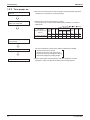
ESiEN09-06
Service Manual
ERQ Condensing Unit Three Phase
ERQ 125/200/250 A7W1B
EKEQD/F/MCBV3 (control box)
EKEXV 50/63/80/100/125/140/200/250
www.daikin.eu
ESiEN09-06
Service Manual
ERQ Condensing Unit Three Phase
ERQ 125/200/250 A7W1B
EKEQD/F/MCBV3 (control box)
EKEXV 50/63/80/100/125/140/200/250
www.daikin.eu
ESiEN09-06
1. Introduction .............................................................................................v
1.1 Safety Cautions ........................................................................................v
Part 1 General Information ........................................................... 1
1. Model Names of Outdoor Unit, Control Box and Expansion Valve Kit....2
1.1 Outdoor Units ...........................................................................................2
1.2 Control Box...............................................................................................3
1.3 Expansion Valve Kit .................................................................................4
2. Combination Table ..................................................................................5
Part 2 Specifications .................................................................... 7
1. Specifications ..........................................................................................8
1.1 Outdoor Units ...........................................................................................8
Part 3 Refrigerant Circuit ........................................................... 11
1. Refrigerant Circuit .................................................................................12
1.1 ERQ 125 A7W1B ...................................................................................12
1.2 ERQ 200 A7W1B ...................................................................................14
1.3 ERQ 250 A7W1B ...................................................................................16
2. Functional Parts Layout ........................................................................18
2.1 ERQ 125 A7W1B ...................................................................................18
2.2 ERQ 200 A7W1B ...................................................................................19
2.3 ERQ 250 A7W1B ...................................................................................20
Part 4 Function............................................................................ 21
1. Function general ...................................................................................22
1.1 Symbol ...................................................................................................22
1.2 Operation Mode......................................................................................23
2. Basic Control.........................................................................................24
2.1
2.2
2.3
2.4
Normal Operation ...................................................................................24
Compressor PI Control...........................................................................25
Step Control of Outdoor Unit Fans .........................................................27
Outdoor Unit Fan Control in Cooling Operation .....................................28
3. Special Control......................................................................................29
3.1
3.2
3.3
3.4
3.5
3.6
Startup Control .......................................................................................29
Oil Return Operation ..............................................................................30
Defrosting Operation ..............................................................................32
Pump-down Residual Operation ............................................................33
Standby ..................................................................................................34
Stopping Operation ................................................................................35
4. Protection Control .................................................................................36
4.1
4.2
4.3
4.4
4.5
4.6
High Pressure Protection Control...........................................................36
Low Pressure Protection Control............................................................37
Discharge Pipe Protection Control .........................................................38
Inverter Protection Control .....................................................................39
STD Compressor Overload Protection...................................................40
Injection Control (only for ERQ 125 A7W1B) .........................................40
5. Other Control.........................................................................................41
5.1 Emergency Operation (only for ERQ 250 A7W1B) ................................41
Table of Contents
i
ESiEN09-06
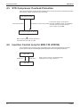
5.2 Demand Operation .................................................................................43
5.3 Heating Operation Prohibition ................................................................43
6. Outline of Control ..................................................................................44
6.1 Thermostat Sensor in Remote Control (only for Z-control) ....................44
6.2 ....................................... Hot Start Control (In Heating Operation Only)45
6.3 Freeze Prevention ..................................................................................46
6.4 Low Outdoor Air Temperature Protection Control ..................................47
Part 5 Control Box EKEQ - CBV3 ................................................ 49
1. Different Systems with their Control Boxes...........................................50
1.1 System A: PAIR......................................................................................50
1.2 System B: MULTI ...................................................................................52
2. X, Y, Z Control.......................................................................................55
2.1 X-Control ................................................................................................55
2.2 Y-Control ................................................................................................56
2.3 Z-Control ................................................................................................57
3. Wiring Diagram of Control Box..............................................................58
3.1 D-box......................................................................................................58
3.2 F-box ......................................................................................................59
4. Attention Points .....................................................................................60
5. System A: EKEQF & EKEQD-box: Installation and Operation Manual.61
6. System B: EKEQM-box: Installation and Operation Manual .................76
Part 6 Test Operation ................................................................. 89
1. Test Operation ......................................................................................90
1.1 Installation Process ................................................................................90
1.2 Procedure and Outline ...........................................................................91
1.3 Operation When Power is Turned On ..................................................104
2. Outdoor Unit PC Board Layout ...........................................................105
3. Field Setting ........................................................................................106
3.1 Field Setting from Remote Control .......................................................106
3.2 Field Setting from Outdoor Unit............................................................114
Part 7 Installation and Operation Manual ................................ 137
Part 8 Troubleshooting ............................................................. 169
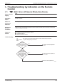
1. Symptom-based Troubleshooting .......................................................171
2. Troubleshooting by Remote Control ...................................................174
2.1
2.2
2.3
2.4
The INSPECTION / TEST Button.........................................................174
Self-diagnosis by Wired Remote Control .............................................175
Remote Control Service Mode .............................................................176
Remote Control Self-Diagnosis Function .............................................178
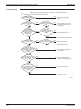
3. Troubleshooting by Indication on the Remote Control ........................185
3.1
3.2
3.3
3.4
3.5
ii
“A0” AHU: Error of External Protection Device.....................................185
“A1” AHU: PC Board Defect .................................................................186
“A3” AHU: Malfunction of Drain Level Control System (S1L) ...............187
“A6” AHU: Fan Motor (M1F) Lock, Overload........................................189
“A9” AHU: Malfunction of Moving Part of Electronic Expansion Valve (Y1E) .190
Table of Contents
ESiEN09-06
3.6
3.7
3.8
3.9
3.10
3.11
3.12
3.13
3.14
3.15
3.16
3.17
3.18
3.19
3.20
3.21
3.22
3.23
3.24
3.25
3.26
3.27
3.28
3.29
3.30
3.31
3.32
3.33
3.34
3.35
3.36
3.37
3.38
3.39
3.40
3.41
3.42
3.43
3.44
3.45
3.46
3.47
3.48
Table of Contents
“AF” AHU: Drain Level above Limit ......................................................192
“AJ” AHU: Malfunction of Capacity Determination Device ...................193
“C4” AHU: Malfunction of Thermistor (R2T) for Heat Exchanger .........194
“C5” AHU: Malfunction of Thermistor (R3T) for Gas Pipes ..................195
“C9” AHU: Malfunction of Thermistor (R1T) for Suction Air .................196
“CJ” AHU: Malfunction of Thermostat Sensor in Remote Control ........197
“E1” Outdoor Unit: PC Board Defect ....................................................198
“E3” Outdoor Unit: Actuation of High Pressure Switch.........................199
“E4” Outdoor Unit: Actuation of Low Pressure Sensor.........................201
“E5” Outdoor Unit: Inverter Compressor Motor Lock............................203
“E6” Outdoor Unit: STD Compressor Motor Overcurrent/Lock.............205
“E7” Outdoor Unit: Malfunction of Outdoor Unit Fan Motor ..................206
“E9” Outdoor Unit: Malfunction of Moving Part of Electronic Expansion
Valve (Y1E, Y2E) .................................................................................209
“F3” Outdoor Unit: Abnormal Discharge Pipe Temperature .................211
“F6” Outdoor Unit: Refrigerant Overcharged........................................212
“H7” Outdoor Unit: Abnormal Outdoor Fan Motor Signal .....................213
“H9” Outdoor Unit: Malfunction of Thermistor (R1T) for Outdoor Air....214
“J2” Outdoor Unit: Current Sensor Malfunction ....................................215
“J3” Outdoor Unit: Malfunction of Discharge Pipe Thermistor
(R3, R31~33T) .....................................................................................216
“J5” Outdoor Unit: Malfunction of Thermistor (R2T), (R7T) for Suction Pipe 217
“J6” Outdoor Unit: Malfunction of Thermistor (R4T) for Outdoor Unit Heat
Exchanger ............................................................................................218
“J7” Outdoor Unit: Malfunction of Liquid Pipe Thermistor (R6T) ..........219
“J9” Outdoor Unit: Malfunction of Subcooling Heat Exchanger Gas Pipe
Thermistor (R5T) ..................................................................................220
“JA” Outdoor Unit: Malfunction of High Pressure Sensor.....................221
“JC” Outdoor Unit: Malfunction of Low Pressure Sensor .....................222
“L4” Outdoor Unit: Malfunction of Inverter Radiating Fin Temperature Rise 223
“L5” Outdoor Unit: Inverter Compressor Abnormal ..............................225
“L8” Outdoor Unit: Inverter Current Abnormal ......................................227
“L9” Outdoor Unit: Inverter Start up Error.............................................229
“LC” Outdoor Unit: Malfunction of Transmission Between Inverter and
Control PC Board .................................................................................231
“P1” Outdoor Unit: Inverter Over-Ripple Protection..............................234
“P4” Outdoor Unit: Malfunction of Inverter Radiating Fin
Temperature Rise Sensor ....................................................................235
“PJ” Outdoor Unit: Faulty Field Setting after Replacing Main PC Board or
Faulty Combination of PC Board..........................................................237
“UO” Outdoor Unit: Low Pressure Drop Due to Refrigerant Shortage or
Electronic Expansion Valve Failure......................................................238
“U1” Reverse Phase, Open Phase.......................................................239
“U2” Outdoor Unit: Power Supply Insufficient or Instantaneous Failure .240
“U3” Outdoor Unit: Check Operation not Executed ..............................243
“U4” Malfunction of Transmission Between AHUs ...............................244
“U5” AHU: Malfunction of Transmission Between Remote Control and AHU.246
“U9” AHU: Malfunction of Transmission Between AHU and
Outdoor Units in the Same System ......................................................247
“UA” Improper Combination of AHU and Outdoor Units, AHUs and
Remote Control ....................................................................................248
“UF” System is not Set yet ...................................................................250
“UH” Malfunction of System, Refrigerant System Address Undefined .251
iii
ESiEN09-06
4. Troubleshooting (OP: Unified ON/OFF Controller) .............................253
4.1 Operation Lamp Blinks .........................................................................253
Part 9 Appendix......................................................................... 259
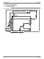
1. Piping Diagrams..................................................................................260
1.1 Outdoor Unit .........................................................................................260
2. Wiring Diagrams for Reference...........................................................263
2.1 Outdoor Unit .........................................................................................263
2.2 Field Wiring ..........................................................................................266
3. List of Electrical and Functional Parts .................................................267
3.1 Outdoor Unit .........................................................................................267
4.
5.
6.
7.
Option List ...........................................................................................269
Thermistor Resistance / Temperature Characteristics........................270
Pressure Sensor .................................................................................272
Method of Checking The Inverter’s Power Transistors and Diode Modules273
Part 10 Precautions for New Refrigerant (R-410A) .................... 275
1. Precautions for New Refrigerant (R-410A) .........................................276
1.1 Outline ..................................................................................................276
1.2 Refrigerant Cylinders............................................................................278
1.3 Service Tools........................................................................................279
Index
............................................................................................. i
Drawings & Flow Charts ............................................................... iii
iv
Table of Contents
ESiEN09-06
Introduction
1. Introduction
1.1
Safety Cautions
Cautions and
Warnings
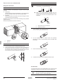
Be sure to read the following safety cautions before conducting repair work.
The caution items are classified into “
Warning” and “
Caution”. The “
Warning”
items are especially important since they can lead to death or serious injury if they are not
followed closely. The “
Caution” items can also lead to serious accidents under some
conditions if they are not followed. Therefore, be sure to observe all the safety caution items
described below.
About the pictograms
This symbol indicates an item for which caution must be exercised.
The pictogram shows the item to which attention must be paid.
This symbol indicates a prohibited action.
The prohibited item or action is shown inside or near the symbol.
This symbol indicates an action that must be taken, or an instruction.
The instruction is shown inside or near the symbol.
After the repair work is complete, be sure to conduct a test operation to ensure that the
equipment operates normally, and explain the cautions for operating the product to the
customer
1.1.1 Caution in Repair
Warning
Be sure to disconnect the power cable plug from the plug socket before
disassembling the equipment for a repair.
Working on the equipment that is connected to a power supply can cause an
electrical shook.
If it is necessary to supply power to the equipment to conduct the repair or
inspecting the circuits, do not touch any electrically charged sections of the
equipment.
If the refrigerant gas discharges during the repair work, do not touch the
discharging refrigerant gas.
The refrigerant gas can cause frostbite.
When disconnecting the suction or discharge pipe of the compressor at the
welded section, release the refrigerant gas completely at a well-ventilated
place first.
If there is a gas remaining inside the compressor, the refrigerant gas or
refrigerating machine oil discharges when the pipe is disconnected, and it can
cause injury.
If the refrigerant gas leaks during the repair work, ventilate the area. The
refrigerant gas can generate toxic gases when it contacts flames.
The step-up capacitor supplies high-voltage electricity to the electrical
components of the outdoor unit.
Be sure to discharge the capacitor completely before conducting repair work.
A charged capacitor can cause an electrical shock.
Do not start or stop the air conditioner operation by plugging or unplugging the
power cable plug.
Plugging or unplugging the power cable plug to operate the equipment can
cause an electrical shock or fire.
v
Introduction
ESiEN09-06
Caution
Do not repair the electrical components with wet hands.
Working on the equipment with wet hands can cause an electrical shock.
Do not clean the air conditioner by splashing water.
Washing the unit with water can cause an electrical shock.
Be sure to provide the grounding when repairing the equipment in a humid or
wet place, to avoid electrical shocks.
Be sure to turn off the power switch and unplug the power cable when cleaning
the equipment.
The internal fan rotates at a high speed, and cause injury.
Do not tilt the unit when removing it.
The water inside the unit can spill and wet the furniture and floor.
Be sure to check that the refrigerating cycle section has cooled down
sufficiently before conducting repair work.
Working on the unit when the refrigerating cycle section is hot can cause burns.
Use the welder in a well-ventilated place.
Using the welder in an enclosed room can cause oxygen deficiency.
1.1.2 Cautions Regarding Products after Repair
Warning
Be sure to use parts listed in the service parts list of the applicable model and
appropriate tools to conduct repair work. Never attempt to modify the
equipment.
The use of inappropriate parts or tools can cause an electrical shock,
excessive heat generation or fire.
When relocating the equipment, make sure that the new installation site has
sufficient strength to withstand the weight of the equipment.
If the installation site does not have sufficient strength and if the installation
work is not conducted securely, the equipment can fall and cause injury.
Be sure to install the product correctly by using the provided standard
installation frame.
Incorrect use of the installation frame and improper installation can cause the
equipment to fall, resulting in injury.
Be sure to install the product securely in the installation frame mounted on a
window frame.
If the unit is not securely mounted, it can fall and cause injury.
Be sure to use an exclusive power circuit for the equipment, and follow the
technical standards related to the electrical equipment, the internal wiring
regulations and the instruction manual for installation when conducting
electrical work.
Insufficient power circuit capacity and improper electrical work can cause an
electrical shock or fire.
vi
For integral units
only
For integral units
only
ESiEN09-06
Introduction
Warning
Be sure to use the specified cable to connect between the AHU and outdoor
units. Make the connections securely and route the cable properly so that there
is no force pulling the cable at the connection terminals.
Improper connections can cause excessive heat generation or fire.
When connecting the cable between the AHU and outdoor units, make sure
that the terminal cover does not lift off or dismount because of the cable.
If the cover is not mounted properly, the terminal connection section can cause
an electrical shock, excessive heat generation or fire.
Do not damage or modify the power cable.
Damaged or modified power cable can cause an electrical shock or fire.
Placing heavy items on the power cable, and heating or pulling the power cable
can damage the cable.
Do not mix air or gas other than the specified refrigerant (R-410A) in the
refrigerant system.
If air enters the refrigerating system, an excessively high pressure results,
causing equipment damage and injury.
If the refrigerant gas leaks, be sure to locate the leak and repair it before
charging the refrigerant. After charging refrigerant, make sure that there is no
refrigerant leak.
If the leak cannot be located and the repair work must be stopped, be sure to
perform pump-down and close the service valve, to prevent the refrigerant gas
from leaking into the room. The refrigerant gas itself is harmless, but it can
generate toxic gases when it contacts flames, such as fan and other heaters,
stoves and ranges.
When replacing the coin battery in the remote control, be sure to disposed of
the old battery to prevent children from swallowing it.
If a child swallows the coin battery, see a doctor immediately.
Caution
Installation of a leakage breaker is necessary in some cases depending on the
conditions of the installation site, to prevent electrical shocks.
Do not install the equipment in a place where there is a possibility of
combustible gas leaks.
If a combustible gas leaks and remains around the unit, it can cause a fire.
Be sure to install the packing and seal on the installation frame properly.
For integral units
If the packing and seal are not installed properly, water can enter the room and only
wet the furniture and floor.
1.1.3 Inspection after Repair
Warning
Check to make sure that the power cable plug is not dirty or loose, then insert
the plug into a power outlet all the way.
If the plug has dust or loose connection, it can cause an electrical shock or fire.
If the power cable and lead wires have scratches or deteriorated, be sure to
replace them.
Damaged cable and wires can cause an electrical shock, excessive heat
generation or fire.
Do not use a joined power cable or extension cable, or share the same power
outlet with other electrical appliances, since it can cause an electrical shock,
excessive heat generation or fire.
vii
Introduction
ESiEN09-06
Caution
Check to see if the parts and wires are mounted and connected properly, and
if the connections at the soldered or crimped terminals are secure.
Improper installation and connections can cause excessive heat generation,
fire or an electrical shock.
If the installation platform or frame has corroded, replace it.
Corroded installation platform or frame can cause the unit to fall, resulting in
injury.
Check the grounding, and repair it if the equipment is not properly grounded.
Improper grounding can cause an electrical shock.
Be sure to measure the insulation resistance after the repair, and make sure
that the resistance is 1 Mohm or higher.
Faulty insulation can cause an electrical shock.
Be sure to check the drainage of the AHU after the repair.
Faulty drainage can cause the water to enter the room and wet the furniture
and floor.
1.1.4 Using Icons
Icons are used to attract the attention of the reader to specific information. The meaning of each
icon is described in the table below:
1.1.5 Using Icons List
Icon
Type of
Information
Note
Description
A “note” provides information that is not indispensable, but may
nevertheless be valuable to the reader, such as tips and tricks.
Note:
Caution
A “caution” is used when there is danger that the reader, through
incorrect manipulation, may damage equipment, loose data, get
an unexpected result or has to restart (part of) a procedure.
Warning
A “warning” is used when there is danger of personal injury.
Reference
A “reference” guides the reader to other places in this binder or
in this manual, where he/she will find additional information on a
specific topic.
Caution
Warning
viii
ESiEN09-06
Part 1
General Information
1. Model Names of Outdoor Unit, Control Box and Expansion Valve Kit....2
1.1 Outdoor Units ...........................................................................................2
1.2 Control Box...............................................................................................3
1.3 Expansion Valve Kit .................................................................................4
2. Combination Table ..................................................................................5
General Information
1
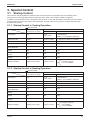
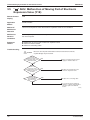
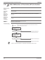
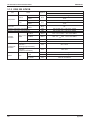
Model Names of Outdoor Unit, Control Box and Expansion Valve Kit
ESiEN09-06
1. Model Names of Outdoor Unit, Control Box and
Expansion Valve Kit
1.1
Outdoor Units
Outlook
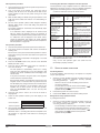
Model name
Series
Inverter Heat Pump
ERQ
Model Name
125A
200A
250A
Power Supply
W1B
W1: 3 phase 380~415V, 50Hz
2
General Information
ESiEN09-06
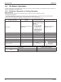
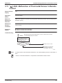
1.2
Model Names of Outdoor Unit, Control Box and Expansion Valve Kit
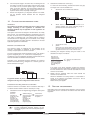
Control Box
Outlook
Types
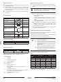
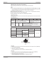
We distinguish 3 types of control boxes:
EKEQD: Z-control
EKEQF: X,Y-control
EKEQM: Z-control (only with VRV outdoor unit, no ERQ)
Control type X
Control of air temperature (Td, Ts or Tr) by means of external device (DDC controller).
Control type Y
Control of evaporating and condensing temperature (Te, Tc) by Daikin control (no DDC needed).
Control type Z
Control of air temperature (Ts or Tr) by Daikin control (no DDC needed).
Legend:
Td
Ts
Tr
Te
Tc
AHU
DDC
General Information
Discharge air control
Suction air control
Room air control
Evaporating temperature control
Condensing temperature control
Air handling unit
Digital controller
3
Model Names of Outdoor Unit, Control Box and Expansion Valve Kit
1.3
ESiEN09-06
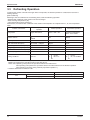
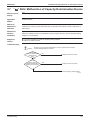
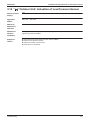
Expansion Valve Kit
Outlook
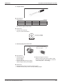
Expansion valve kit installation drawing:
Model name
Limits for outdoor unit (expansion valve kit).
Outdoor unit (class)
125
200
250
EKEXV kit
EKEXV63~140
EKEXV100~250
EKEXV125~250
Depending on the heat exchanger, a connectable EKEXV (expansion valve kit) must be
selected to these limitations.
EKEXV class
63
80
100
125
140
200
250
Allowed heat exchanger volume (dm3)
Minimum
Maximum
1.66
2.08
2.09
2.64
2.65
3.30
3.31
4.12
4.13
4.62
4.63
6.60
6.61
8.25
Allowed heat exchanger capacity (kW)
Minimum
Maximum
6.3
7.8
7.9
9.9
10.0
12.3
12.4
15.4
15.5
17.6
17.7
24.6
24.7
30.8
Saturated suction temperature (SST) = 6°C, SH (superheat) = 5 K, air temperature = 27°C DB /
19°C WB.
4
General Information
ESiEN09-06
Combination Table
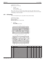
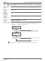
2. Combination Table
Control box
Outdoor unit
Expansion valve kit
EKEQDCBV3 EKEQFCBV3 EKEXV63
three ERQ125
phase
ERQ200
P
P
P
P
ERQ250
P
P
P
EKEXV80 EKEXV100 EKEXV125 EKEXV140 EKEXV200 EKEXV250
P
P
P
P
-
-
-
-
P
P
P
P
P
-
-
-
P
P
P
P
Heat pump
P: Pair: Combination depending on AHU heat exchanger volume and capacity.
EKEXV class
63
80
100
125
140
200
250
Allowed heat exchanger volume (dm3)
Minimum
Maximum
1.66
2.08
2.09
2.64
2.65
3.3
3.31
4.12
4.13
4.62
4.63
6.6
6.61
8.25
Allowed heat exchanger capacity (kW)
Minimum
Maximum
6.3
7.8
7.9
9.9
10
12.3
12.4
15.4
15.5
17.6
17.7
24.6
24.7
30.8
Saturated suction temperature (SST) = 6°C, SH (superheat) = 5 K, air temperature = 27°C DB /
19°C WB.
Note:
General Information
If conflicting result occurs, capacity selection has priority over volume.
5
Combination Table
6
ESiEN09-06
General Information
ESiEN09-06
Part 2
Specifications
1. Specifications ..........................................................................................8
1.1 Outdoor Units ...........................................................................................8
Specifications
7
Specifications
ESiEN09-06
1. Specifications
1.1
Outdoor Units
Heat Pump 50Hz Standard Series ERQ 125/200/250 A7W1B
TECHNICAL SPECIFICATIONS
ERQ125A7W1B
ERQ200A7W1B
ERQ250A7W1B
Nominal
capacity
Cooling
kW
14,0
22,4
28,0
Heating
kW
16,0
25,0
31,5
COP
Cooling
3,98
4,29
3,77
4,09
4,00
4,50
Capacity range
Heating
HP
5
8
10
Nominal input Cooling
kW
3,52
5,22
7,42
Heating
kW
4,00
5,56
7,70
PED category
Casing
2
Colour
Daikin white
Material
Dimensions
Unit
Packing
Weight
Packing
information
Heat
exchanger
Painted galvanised steel
Height
mm
Width
mm
Depth
mm
Height
mm
Width
mm
Depth
mm
1680
635
930
765
1855
796
1055
860
Unit
kg
159
187
Packed unit
kg
182
217
Carton
kg
3,8
Wood
kg
19,15
20,85
Plastic
kg
0,215
0,265
mm
1483
Specifications Length
1778
Nr of rows
54
2
Nr of passes
Face area
m²
8
18
1,762
2,112
Nr of stages
2
Empty tubeplate
hole
0
Tube type
Fin
HI-XSS (8)
Type
Non-symmetric waffle louvre
Treatment
Hydrophylic and anti corrosion resistant
Type
Propeller
Quantity
Air flow rate
(nominal at
230V)
1
Cooling
m³/min
95
171
185
Heating
m³/min
95
171
185
External static pressure
Pa
78 Pa in high static pressure
Discharge direction
Motor
Vertical
Quantity
1
Model
Brushless DC
Speed
rpm
Output
W
Speed
(nominal)
Cooling
rpm
Speed
(nominal)
Heating
Compressor
350
750
rpm
Quantity
Motor
1
Quantity
2
1
Model
Inverter
Speed
rpm
Motor
output
kW
6300
2,8
Type
7980
6300
3,8
1,2
Hermetically sealed scroll compressor
Crankcase W
heater
Quantity
33
0
Model
1
ON - OFF
Speed
rpm
Motor
output
kW
Type
Crankcase W
heater
8
273
4,02
Fin pitch
Fan
240
2900
4,5
Hermetically sealed scroll compressor
33
Specifications
ESiEN09-06
Specifications
TECHNICAL SPECIFICATIONS
Operation
range
ERQ125A7W1B
Min
°CDB
Max
°CDB
43
Heating
Min
°CWB
-20
Max
°CWB
15
Sound power
dBA
72
Sound pressure
dBA
54
Refrigerant
Type
78
57
kg
6,2
7,7
Control
8,4
Electronic expansion valve
Nr of circuits
1
Refrigerant oil Type
Synthetic (ether) oil
Charged volume
l
1,7
2,1
Type
Diameter
(OD)
Gas
58
R-410A
Charge
Liquid
ERQ250A7W1B
-5
Sound level
(nominal)
Piping
connections
ERQ200A7W1B
Cooling
mm
9,52
Type
Diameter
(OD)
4,3
Brazing connection
Brazing connection
mm
15,9
19,1
22,2
Discharge gas Type
Diameter
(OD)
Drain
mm
Quantity
Diameter
(OD)
mm
Heat insulation
Both liquid and gas
Max total length
m
55
Defrost method
Reversed cycle
Defrost control
Sensor for outdoor heat exchanger temperature
Capacity control method
Inverter controlled
Capacity control [%]
~ 100
Safety devices
High pressure switch
Fan driver overload protector
Overcurrent relay
Inverter overload protector
PC board fuse
Standard
accessories
Item
Standard
accessories
Item
Standard
accessories
Item
Installation manual
Quantity
1
Operation manual
Quantity
1
Connection pipes
Quantity
4
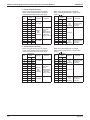
Notes
Nominal cooling capacities are based on: indoor temperature: 27°CDB/19°CWB, outdoor temperature: 35°CDB,
equivalent refrigerant piping: 7,5m, level difference: 0m.
Nominal heating capacities are based on: indoor temperature: 20°CDB, outdoor temperature: 7°CDB/6°CWB,
equivalent refrigerant piping: 7,5m, level difference: 0m.
Sound power level is an absolute value that a sound generates.
Sound pressure level is a relative value, depending on the distance and acoustic environment. For more details,
please refer to sound level drawings.
Sound values are measured in a semi-anechoic room.
ELECTRICAL SPECIFICATIONS
ERQ125A7W1B
Power supply Name
3N~
Frequency
Hz
50
Voltage
V
400
Nominal
Cooling
running
current (RLA) Heating
A
5,1
7,5
11,3
A
5,8
8,2
11,1
Starting current (MSC)
A
Zmax
Minimum Ssc value
kVA
Min circuit amps (MCA)
A
Max fuse amps (MFA)
A
Total overcurrent amps
(TOCA)
A
Full load amps (FLA)
Voltage range
Wiring
connections
ERQ250A7W1B
W1
Phase
Current
ERQ200A7W1B
A
V
74
-
0,27
-
889
842
11,9
18,5
21,6
16
15,6
0,4
25
16,5
31,5
0,7
0,9
400 ±10%
For power
supply
Quantity
5
Remark
Earth wire included
For
connection
with indoor
Quantity
2
Remark
F1 - F2
Power supply intake
Specifications
Both AHU and outdoor unit
9
Specifications
ESiEN09-06
ELECTRICAL SPECIFICATIONS
Notes
ERQ125A7W1B
ERQ200A7W1B
ERQ250A7W1B
(1) European/international technical standard setting the limits for voltage changers, voltage fluctuations and flicker in public low-voltage supply systems for
equipment with rated ≤ 75A.
(2) European/international technical standard setting the limits for harmonic currents produced by equipment connected to public low-voltage system with
input current > 16A and ≤ 75A per phase.
(3) Short-circuit power.
(4) System impedance.
Notes:
-
10
MFA is used to select the circuit breaker and the ground fault circuit interrupter (earth
leakage circuit breaker).
MSC means the maximum current during start up of the compressor.
Maximum allowable voltage range variation between phases is 2%.
RLA is based on following conditions: indoor temperature: 27°CDB/19°CWB, outdoor
temperature: 35°CDB.
Select wire size based on the value of MCA or TOCA.
TOCA means the total value of each OC set.
Voltage range: units are suitable for use on electrical systems where voltage supplied
to unit terminal is not below or above listed range limits.
FLA means the full load amps of the fan motor.
In accordance with EN/IEC 61000-3-11 (1), respectively EN/IEC 61000-3-12 (2), it may
be necessary to consult the distribution network operator to ensure that the equipment
is connected only to a supply with Zsys (4) ≤ Zmax, respectively Ssc (3) ≥ minimum Ssc
value.
Specifications
ESiEN09-06
Part 3
Refrigerant Circuit
1. Refrigerant Circuit .................................................................................12
1.1 ERQ 125 A7W1B ...................................................................................12
1.2 ERQ 200 A7W1B ...................................................................................14
1.3 ERQ 250 A7W1B ...................................................................................16
2. Functional Parts Layout ........................................................................18
2.1 ERQ 125 A7W1B ...................................................................................18
2.2 ERQ 200 A7W1B ...................................................................................19
2.3 ERQ 250 A7W1B ...................................................................................20
Refrigerant Circuit
11
Refrigerant Circuit
ESiEN09-06
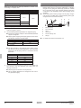
1. Refrigerant Circuit
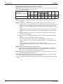
1.1
ERQ 125 A7W1B
No. in
refrigerant
Symbol
system
diagram
Major Function
A
M1C
Inverter compressor (INV)
Inverter compressor is operated on frequencies between 52Hz and 188Hz by using
the inverter. The number of operating steps is as follows when Inverter compressor is
operated.
RXYQ5P: 18 steps
D
M1F
Inverter fan
Since the system is of air heat exchanging type, the fan is operated at 9-step rotation
speed by using the inverter.
E
Y1E
Electronic expansion valve
(Main: EV1)
While in heating operation, PI control is applied to keep the outlet superheated degree
of air heat exchanger constant.
G
Y1S
Solenoid valve (Hot gas: SVP) Used to prevent the low pressure from transient falling.
J
Y2S
Solenoid valve (Oil return: SVO) Used to return oil from the accumulator to the compressor.
K
Y4S
Solenoid valve (Injection) SVT
Used to cool the compressor by injecting refrigerant when the compressor discharge
temperature is high.
M
Y3S
4-way valve
Used to switch the operation mode between cooling and heating.
N
S1NPH High pressure sensor
Used to detect high pressure.
O
S1NPL Low pressure sensor
Used to detect low pressure.
P
S1PH
HP pressure switch (For INV
compressor)
In order to prevent the increase of high pressure when a malfunction occurs, this
switch is activated at high pressure of 4.0 MPa or more to stop the compressor
operation.
T
—
Pressure regulating valve 1
This valve opens at a pressure of 4.0 MPa for prevention of pressure increase, thus
resulting in no damage of functional parts due to the increase of pressure in
transportation or storage.
W
—
Capillary tube
Used to return the refrigerating oil separated through the oil separator to the
compressor.
1
R1T
Thermistor (Outdoor air: Ta)
Used to detect outdoor temperature, correct discharge pipe temperature, and others.
2
R2T
Thermistor (Suction pipe: Ts)
Used to detect suction pipe temperature.
3
R3T
Thermistor (INV discharge
pipe: Tdi)
Used to detect discharge pipe temperature, make the temperature protection control of
compressor, and others.
4
R4T
Thermistor (Heat exchanger
deicer: Tb)
Used to detect liquid pipe temperature of air heat exchanger, determine defrosting
operation, and others.
5
R6T
Thermistor (Liquid pipe Tl)
Used to detect liquid pipe temperature.
R7T
Thermistor (Accumulator inlet
Ts1)
Used to detect gas pipe temperature at the accumulator inlet. Keep the suction
superheated degree constant in heating operation, and others.
6
12
Name
Refrigerant Circuit
ESiEN09-06
Refrigerant Circuit
ERQ 125 A7W1B
T
FILTER
PRESSURE
REGULATING VALVE
(CHECK VALVE TYPE)
5
SV
4
ACCUMULATOR
ELECTRONIC
EXPANSION VALVE
SOLENOID
VALVE K
E
CAPILLARY TUBE
6
D
M
FOUR WAY
VALVE
SENPH
HIGH PRESSURE
SENSOR
N
CHECK VALVE
1
FILTER
FILTER
SV
CAPILLARY
TUBE
FILTER
OIL
SEPARATOR
FILTER
HIGH PRESSURE
SWITCH
SOLENOID
VALVE
HPS
P
FILTER
J
3
COMPRESSOR
INV
CAPILLARY
TUBE
SV
G
SOLENOID
VALVE
A
W
2
LOW PRESSURE
SENSOR
SENPL
O
STOP VALVE (WITH SERVICE PORT ø7.9mm FLARE CONNECTION)
3D050782
Refrigerant Circuit
13
Refrigerant Circuit
1.2
ESiEN09-06
ERQ 200 A7W1B
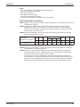
No. in
refrigerant Symbol
system
diagram
Major Function
A
M1C
Inverter compressor (INV)
Inverter compressor is operated on frequencies between 52Hz and 266Hz by using
the inverter, while Standard compressor is operated with commercial power supply
only. The number of operating steps is as follows when Inverter compressor is
operated in combination with Standard compressor.
RXYQ8P: 24 steps
D
M1F
Inverter fan
Since the system is of air heat exchanging type, the fan is operated at 9-step rotation
speed by using the inverter.
E
Y1E
Electronic expansion valve
(Main: EV1)
While in heating operation, PI control is applied to keep the outlet superheated degree
of air heat exchanger constant.
F
Y2E
Electronic expansion valve
(Subcool: EV2)
PI control is applied to keep the outlet superheated degree of subcooling heat
exchanger constant.
G
Y1S
Solenoid valve (Hot gas: SVP) Used to prevent the low pressure from transient falling.
J
Y2S
Solenoid valve (Oil return: SVO) Used to return oil from the accumulator to the compressor.
Y3S
4-way valve
M
14
Name
Used to switch the operation mode between cooling and heating.
N
S1NPH High pressure sensor
Used to detect high pressure.
O
S1NPL Low pressure sensor
Used to detect low pressure.
P
S1PH
T
HP pressure switch (For INV
compressor)
In order to prevent the increase of high pressure when a malfunction occurs, this
switch is activated at high pressure of 4.0 MPa or more to stop the compressor
operation.
—
Pressure regulating valve
(Liquid pipe)
This valve opens at a pressure of 4.0 MPa for prevention of pressure increase, thus
resulting in no damage of functional parts due to the increase of pressure in
transportation or storage.
V
—
Subcooling heat exchanger
Used to subcool liquid refrigerant from the electronic expansion valve (cooling) or
AHUs (heating).
W
—
Capillary tube
Used to return the refrigerating oil separated through the oil separator to the INV
compressor.
1
R1T
Thermistor (Outdoor air: Ta)
Used to detect outdoor temperature, correct discharge pipe temperature, and others.
2
R2T
Thermistor (Suction pipe: Ts)
Used to detect suction pipe temperature.
3
R3T
Thermistor (INV discharge
pipe: Tdi)
Used to detect discharge pipe temperature, make the temperature protection control of
compressor, and others.
4
R4T
Thermistor (Heat exchanger
deicer: Tb)
Used to detect liquid pipe temperature of air heat exchanger, determine defrosting
operation, and others.
5
R5T
Thermistor (Subcooling heat
exchanger gas pipe: Tsh)
Used to detect gas pipe temperature on the evaporation side of subcooling heat
exchanger, keep the superheated degree at the outlet of subcooling heat exchanger
constant, and others.
6
R6T
Thermistor (Receiver outlet
liquid pipe: Tl)
Used to detect receiver outlet liquid pipe temperature.
7
R7T
Used to detect gas pipe temperature at the accumulator inlet. Keep the suction
Thermistor (Accumulator inlet) superheated degree constant in heating operation, and others.
Refrigerant Circuit
ESiEN09-06
Refrigerant Circuit
ERQ 200 A7W1B
CHECK VALVE
ELECTRONIC EXPANSION VALVE
E
ELECTRONIC
EXPANSION VALVE
V
F
5
ACCUMULATOR
FILTER
PRESSURE
REGULATING VALVE T
(CHECK VALVE TYPE)
4
7
FILTER
D
M
6
SV
SENPH
HIGH PRESSURE
SENSOR
N
SOLENOID
VALVE
1
CHECK VALVE
G
HIGH PRESSURE
SWITCH
HPS
P
CAPILLARY
TUBE
OIL
SEPARATOR
FILTER
3
FILTER
A
FILTER
COMPRESSOR
INV
W
CAPILLARY TUBE
SV
FILTER
SOLENOID
VALVE
J
O
LOW PRESSURE
SENSOR
SENPL
2
STOP VALVE (WITH SERVICE PORT ø7.9mm FLARE CONNECTION)
3D050783
Refrigerant Circuit
15
Refrigerant Circuit
1.3
ESiEN09-06
ERQ 250 A7W1B
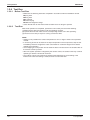
No. in
refrigerant Symbol
system
diagram
Major Function
A
M1C
Inverter compressor (INV)
B
M2C
Standard compressor 1
(STD1)
D
M1F
Inverter fan
Since the system is of air heat exchanging type, the fan is operated at 9-step rotation
speed by using the inverter.
E
Y1E
Electronic expansion valve
(Main: EV1)
While in heating operation, PI control is applied to keep the outlet superheated degree
of air heat exchanger constant.
F
Y2E
Electronic expansion valve
(Subcool: EV3)
PI control is applied to keep the outlet superheated degree of subcooling heat
exchanger constant.
Inverter compressor is operated on frequencies between 52Hz and 210Hz by using
the inverter, while Standard compressor is operated with commercial power supply
only. The number of operating steps is as follows when Inverter compressor is
operated in combination with Standard compressor.
RXYQ10, 12P: 37 steps
G
Y1S
Solenoid valve (Hot gas: SVP) Used to prevent the low pressure from transient falling.
J
Y2S
Solenoid valve (Oil return: SVO) Used to return oil from the accumulator to the compressor.
Y3S
4-way valve
M
Used to switch the operation mode between cooling and heating.
N
S1NPH High pressure sensor
Used to detect high pressure.
O
S1NPL Low pressure sensor
Used to detect low pressure.
P
S1PH
HP pressure switch (For INV
compressor)
Q
S2PH
HP pressure switch (For STD
compressor 1)
U
—
Pressure regulating valve
(Liquid pipe)
This valve opens at a pressure of 4.0 MPa for prevention of pressure increase, thus
resulting in no damage of functional parts due to the increase of pressure in
transportation or storage.
V
—
Subcooling heat exchanger
Used to subcool liquid refrigerant from the electronic expansion valve (cooling) or
AHUs (heating).
W
—
Capillary tube
Used to return the refrigerating oil separated through the oil separator to the INV
compressor.
X
—
Capillary tube
Used to return the refrigerating oil separated through the oil separator to the STD1
compressor.
1
R1T
Thermistor (Outdoor air: Ta)
Used to detect outdoor temperature, correct discharge pipe temperature, and others.
2
R2T
Thermistor (Suction pipe: Ts)
Used to detect suction pipe temperature.
3
R31T
Thermistor (INV discharge
pipe: Tdi)
4
R32T
Thermistor (STD1 discharge
pipe: Tds1)
5
R4T
Thermistor (Heat exchanger
deicer: Tb)
Used to detect liquid pipe temperature of air heat exchanger, determine defrosting
operation, and others.
6
R5T
Thermistor (Subcooling heat
exchanger gas pipe: Tsh)
Used to detect gas pipe temperature on the evaporation side of subcooling heat
exchanger, keep the superheated degree at the outlet of subcooling heat exchanger
constant, and others.
7
R6T
Thermistor (Liquid pipe: Tl)
Used to detect liquid pipe temperature.
R7T
Thermistor (Accumulator inlet) Used to detect gas pipe temperature at the accumulator inlet. Keep the suction
superheated degree constant in heating operation, and others.
8
16
Name
In order to prevent the increase of high pressure when a malfunction occurs, this
switch is activated at high pressure of 4.0 MPa or more to stop the compressor
operation.
Used to detect discharge pipe temperature, make the temperature protection control of
compressor, and others.
Refrigerant Circuit
ESiEN09-06
Refrigerant Circuit
ERQ 250 A7W1B
CHECK VALVE
ELECTRONIC EXPANSION VALVE
E
FILTER
V
F
PRESSURE REGULATING VALVE
U
ELECTRONIC
EXPANSION VALVE
6
ACCUMULATOR
5
8
FILTER
D
M
FOUR WAY VALVE
7
SENPH
HIGH PRESSURE SENSOR
1
G
CHECK VALVE
CHECK VALVE
FILTER
FILTER
HIGH PRESSURE
SWITCH
HPS
P
CAPILLARY
TUBE
3
A
FILTER
FILTER
SOLENOID VALVE
J
Q
HPS
COMPRESSOR
INV
CAPILLARY TUBE
CAPILLARY X
TUBE
HIGH PRESSURE
SENSOR
4
FILTER
W
FILTER
SV
OIL
SEPARATOR
SOLENOID
VALVE
OIL
SEPARATOR
SV
N
COMPRESSOR
STD1
B
LOW PRESSURE SENPL
SENSOR O
2
STOP VALVE (WITH SERVICE PORT ø7.9mm FLARE CONNECTION)
3D050784
Refrigerant Circuit
17
Functional Parts Layout
ESiEN09-06
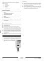
2. Functional Parts Layout
2.1
ERQ 125 A7W1B
Plan
Accumulator ass’y
Heat exchanger
Solenoid valve
(accumulatorACCUMULATOR
oil return)
(Y2S)
Solenoid valve (injection)
(Y4S)
4-Way valve
(Y3S)
Solenoid valve
(Hot gas bypass)
(Y1S)
Pressure switch (High
pressure protection)
(S1PH)
Pressure sensor
(Low pressure)
Thermistor (M1C,
Discharge pipe)
THERMISTOR
(R3T)
(S1NPL)
Front View
Fan motor
(M1F)
Thermistor (Accumulator)
(R7T)
Pressure sensor
(High pressure)
(S1NPH)
Pressure switch (High pressure protection)
(S1PH)
4 way valve
(Y3S)
Solenoid valve (Hot gas bypass)
(Y1S)
Electronic
expansion valve
(Y1E)
Thermistor (Air)
(R1T)
Thermistor (Suction pipe)
(R2T)
Thermistor (Coil)
(R4T)
Thermistor (Liqite pipe)
(R6T)
Solenoid valve (Accumulator oil return)
(Y2S)
Crank case heater wire
(E1HC)
Compressor (Inverter)
(M1C)
18
Refrigerant Circuit
ESiEN09-06
2.2
Functional Parts Layout
ERQ 200 A7W1B
Plan
Heat exchanger
Accumulator
High pressure sensor
(S1NPH)
Thermistor (M1C,
Discharge pipe)
(R3T)
Pressure switch (High
pressure protection)
(S1PH)
Front View
Fan motor
(M1F)
Thermistor (Sub cooling
heat-exchanger)
Thermistor (Inlet pipe of accumulator)
(R7T)
Pressure sensor
(High pressure)
Electronic expansion valve
(Y2E)
(S1NPH)
Electronic expansion valve
(Y1E)
4-Way valve
(Y3S)
Thermistor (Air)
(R1T)
Solenoid valve (Hot gas bypass)
(Y1S)
Thermistor (Coil)
(R4T)
Thermistor (Liquid pipe)
(R6T)
Pressure sensor
(Low pressure)
(S1NPL)
Compressor (Inverter)
Conp. lead wire (Inverter)
(Y2S)
(M1C)
Thermistor (Suction pipe)
(R2T)
Refrigerant Circuit
(M1C)
Solenoid valve
(Accumulator oil return)
Crank case heater wire
(E1HC)
19
Functional Parts Layout
2.3
ESiEN09-06
ERQ 250 A7W1B
Plan
Accumulator
Pressure switch (High
pressure protection)
Heat exchanger
(S1PH)
Pressure switch (High
pressure protection)
(S2PH)
Thermistor (M1C, Discharge pipe)
Thermistor (M2C, Discharge pipe)
(R31T)
(R32T)
Front View
Fan motor
(M1F)
Thermistor (Sub cooling heat-exchanger)
(R5T)
Thermistor (Inlet pipe of accumulator)
Pressure sensor
(High pressure)
(R7T)
Electronic expansion valve
(S1NPH)
(Y2E)
Electronic expansion valve
(Y1E)
4-Way valve
(Y3S)
Thermistor (Air)
(R1T)
Solenoid valve (Hot gas bypass)
(Y1S)
Thermistor (Coil)
(R4T)
Thermistor (Liquid pipe)
(R6T)
Conp. lead wire (STD1)
(M2C)
Pressure sensor
(Low pressure)
(S1NPL)
Compressor (STD1)
Solenoid valve
(Accumulator oil return)
(Y2S)
Thermistor (Suction pipe)
(R2T)
Compressor (Inverter)
(M1C)
(M2C)
Crank case heater wire
Conp. lead wire (Inverter) (E2HC)
(M1C)
Crank case heater wire
(E1HC)
20
Refrigerant Circuit
ESiEN09-06
Part 4
Function
1. Function general ...................................................................................22
1.1 Symbol ...................................................................................................22
1.2 Operation Mode......................................................................................23
2. Basic Control.........................................................................................24
2.1
2.2
2.3
2.4
Normal Operation ...................................................................................24
Compressor PI Control...........................................................................25
Step Control of Outdoor Unit Fans .........................................................27
Outdoor Unit Fan Control in Cooling Operation .....................................28
3. Special Control......................................................................................29
3.1
3.2
3.3
3.4
3.5
3.6
Startup Control .......................................................................................29
Oil Return Operation ..............................................................................30
Defrosting Operation ..............................................................................32
Pump-down Residual Operation ............................................................33
Standby ..................................................................................................34
Stopping Operation ................................................................................35
4. Protection Control .................................................................................36
4.1
4.2
4.3
4.4
4.5
4.6
High Pressure Protection Control...........................................................36
Low Pressure Protection Control............................................................37
Discharge Pipe Protection Control .........................................................38
Inverter Protection Control .....................................................................39
STD Compressor Overload Protection...................................................40
Injection Control (only for ERQ 125 A7W1B) .........................................40
5. Other Control.........................................................................................41
5.1 Emergency Operation (only for ERQ 250 A7W1B) ................................41
5.2 Demand Operation .................................................................................43
5.3 Heating Operation Prohibition ................................................................43
6. Outline of Control ..................................................................................44
6.1
6.2
6.3
6.4
Function
Thermostat Sensor in Remote Control (only for Z-control) ....................44
Hot Start Control (In Heating Operation Only)........................................45
Freeze Prevention ..................................................................................46
Low Outdoor Air Temperature Protection Control ..................................47
21
Function general
ESiEN09-06
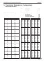
1. Function general
1.1
Symbol
Symbol
Electric symbol
Description or function
20S1
Y3S
Four way valve (Energize during heating)
DSH
–
Discharge pipe superheated degree
DSHi
–
Discharge pipe superheat of inverter compressor
DSHs
–
Discharge pipe superheat of standard compressor
EV
–
Opening of electronic expansion valve
EV1
Y1E
Electronic expansion valve for main heat exchanger
EV2
Y2E
Electronic expansion valve for sub-coolig heat exchanger
HTDi
–
Value of INV compressor discharge pipe temperature (R31T) compensated with
outdoor air temperature
HTDs
–
Value of STD compressor discharge pipe temperature (R32T, R33T) compensated
with outdoor air temperature
Pc
S1NPH
Value detected by high pressure sensor
Pe
S1NPL
Value detected by low pressure sensor
SH
–
Evaporator outlet superheat
SHS
–
Target evaporator outlet superheat
SVO
Y2S
Solenoid valve for oil return
SVP
Y1S
Solenoid valve for hot gas bypass
SVT
Y4S
Solenoid valve for injection
Ta
R1T (A1P)
Outdoor air temperature
Tb
R4T
Heat exchanger outlet temperature at cooling
Ts2
R2T
Suction pipe temperature detected with the suction pipe thermistor (R2T)
Tsh
R5T (–)
Temperature detected with the subcooling heat exchanger outlet thermistor (R5T)
Tc
–
High pressure equivalent saturation temperature
TcS
–
Target temperature of Tc
Te
–
Low pressure equivalent saturation temperature
TeS
–
Target temperature of Te
Tfin
R1T
Inverter fin temperature
Tl
R6T
Liquid pipe temperature detected with the liquid pipe thermistor (R6T)
Tp
–
Calculated value of compressor port temperature
Ts1
R7T
Suction pipe temperature detected with the accumulator inlet thermistor
22
Function
ESiEN09-06
1.2
Function general
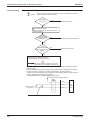
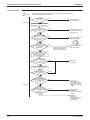
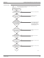
Operation Mode
Operation in
stop mode
AHU stop or
thermostat OFF
AHU thermostat ON
Malfunction/Standby (Retry)
Restart standby
(Compressor stop)
Pressure
equalization
prior to startup
AHU stop or
thermostat OFF
Startup control
Operation mode
changeover
• Cooling startup control
(After completion of
startup control)
• Heating startup control
Operation
mode
changeover
Normal operation
• Compressor PI control
• Motorized valve PI control
• Protection control
Cooling
AHU thermostat ON
After completion of
startup control
Malfunction/
Standby
(Retry)
Pump-down
residual
operation
Malfunction/Standby
(Retry)
AHU stop or
thermostat off (After
completion of oil return
or defrost control)
AHU stop or
thermostat OFF
Heating
Large capacity
startup
in operation
Malfunction/Standby
(Retry)
Oil
return IN
conditions are met.
Yes
Oil return operation
No
Outdoor unit
rotation
Defrost IN
conditions are met.
Yes
Defrosting operation
No
Operation mode changeover
(after completion of oil return
or defrost control)
*)
In the event AHU stops or the
thermostat turns OFF while in oil
return operation or defrosting
operation, pump-down residual
operation is performed on
completion of the oil return
operation or defrosting operation.
Function
23
Basic Control
ESiEN09-06
2. Basic Control
2.1
Normal Operation
2.1.1 List of Functions in Normal Operation
Compressor
⎯
Outdoor unit fan
Four way valve
Main motorized valve
Subcool heat exchanger
electronic expansion valve
20S1
EV1
Function of Functional Part
Normal Cooling
Normal Heating
PI control, High pressure
PI control, High pressure
Low pressure
protection, Low pressure
(M1C, M2C) protection,
protection, Td protection,
protection, Td protection,
INV protection,
INV protection,
(M1F)
Cooling fan control
Step 7 or 8
(Y1R)
OFF
ON
(Y1E)
480 pls
PI control
EV2
(Y2E)
PI control
PI control
Hot gas bypass valve
SVP
(Y1S)
OFF
Accumulator oil return valve SV0
(Y2S)
ON
Energized when the system is set
to low pressure control mode
ON
Part Name
Fan
24
Symbol
(Electric
Symbol)
AHU actuator
Thermostat ON unit
Stopping unit
Normal cooling
ON
OFF
Normal heating
ON
OFF
Function
ESiEN09-06
2.2
Basic Control
Compressor PI Control
2.2.1 For Z-Control
Carries out the compressor capacity PI control to maintain Te at constant during cooling
operation and Tc at constant during heating operation to ensure stable unit performance.
[Cooling operation]
Controls compressor capacity to adjust Te to Te : Low pressure equivalent saturation
achieve target value (TeS).
temperature (°C)
Te set value (Make this setting while in Setting TeS : Target Te value
mode 2.)
(Varies depending on Te setting, operating
frequency, etc.)
Te setting
L
M (Normal)
H
(factory
setting)
3
6
9
[Heating operation]
Controls compressor capacity to adjust Tc to Tc : High pressure equivalent saturation
achieve target value (TcS).
temperature (°C)
Te set value (Make this setting while in Setting TcS : Target Tc value
mode 2.)
(Varies depending on Tc setting, operating
frequency, etc.)
Tc setting
L
M (Normal)
H
(factory
setting)
43
46
49
2.2.2 For X-, Y-Control
See chapter “Field Setting”.
Function
25
Basic Control
ESiEN09-06
Compressor Step Control
Compressor operations vary with the following steps.
Stand-alone installation
ERQ 200
ERQ 125
ERQ 250
INV
STD1
52 Hz
STEP
No.
1
52 Hz
OFF
2
56 Hz
2
56 Hz
OFF
62 Hz
3
62 Hz
3
62 Hz
OFF
4
68 Hz
4
68 Hz
4
68 Hz
OFF
5
74 Hz
5
74 Hz
5
74 Hz
OFF
6
80 Hz
6
80 Hz
6
80 Hz
OFF
7
88 Hz
7
88 Hz
7
88 Hz
OFF
8
96 Hz
8
96 Hz
8
96 Hz
OFF
9
104 Hz
9
104 Hz
9
104 Hz
OFF
10
110 Hz
10
110 Hz
10
110 Hz
OFF
11
116 Hz
11
116 Hz
11
116 Hz
OFF
12
124 Hz
12
124 Hz
12
124 Hz
OFF
13
132 Hz
13
132 Hz
13
132 Hz
OFF
14
144 Hz
14
144 Hz
14
144 Hz
OFF
15
158 Hz
15
158 Hz
15
158 Hz
OFF
16
166 Hz
16
166 Hz
16
166 Hz
OFF
17
176 Hz
17
176 Hz
17
176 Hz
OFF
18
188 Hz
18
188 Hz
18
188 Hz
OFF
19
202 Hz
19
202 Hz
OFF
20
210 Hz
20
210 Hz
OFF
21
218 Hz
21
52 Hz
ON
22
232 Hz
22
62 Hz
ON
23
248 Hz
23
68 Hz
ON
24
266 Hz
24
74 Hz
ON
25
80 Hz
ON
26
88 Hz
ON
27
96 Hz
ON
28
104 Hz
ON
29
116 Hz
ON
30
124 Hz
ON
31
132 Hz
ON
32
144 Hz
ON
33
158 Hz
ON
34
176 Hz
ON
35
188 Hz
ON
36
202 Hz
ON
37
210 Hz
ON
52 Hz
STEP
No.
1
2
56 Hz
3
STEP
No.
1
INV
INV
Notes:
1. INV : Inverter compressor
STD1 : Standard compressor 1
2. Depending on the operating conditions of compressors, the compressors may run in patterns
other than those aforementioned.
26
Function
ESiEN09-06
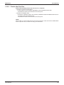
2.3
Basic Control
Step Control of Outdoor Unit Fans
Used to control the revolutions of outdoor unit fans in the steps listed in table below, according
to condition changes.
STEP
No.
0
1
2
3
4
5
6
7
8
*
Function
Fan revolutions (rpm)
ERQ 125
ERQ 200
ERQ 250
0
0
0
285
350
350
315
370
370
360
400
400
450
450
460
570
540
560
710
670
680
Cooling: 951
Cooling:
821
760
Heating: 941
Heating: 800
Cooling: 951 Cooling: 796 Cooling: 821
Heating: 941 Heating: 780 Heating: 800
Figures listed above are all those controlled while in standard mode, which vary when the
system is set to high static pressure or capacity precedence mode.
27
Basic Control
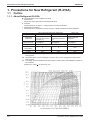
2.4
ESiEN09-06
Outdoor Unit Fan Control in Cooling Operation
While in cooling operation, if the outdoor temperature is low, this mode provides high-pressure
control using the outdoor unit fan to retain appropriate liquid pressure, thus ensuring refrigerant
circulation rate to be supplied to AHU.
Upper limit of fan
revolutions: Step 8
Pc<2.75MPa
Pc>3.24MPa
Upper limit of outdoor unit
fan revolutions
Step 7
*For fan revolutions in each step,
refer to information on page 107.
PI control
Lapse of 20 sec.
PI control
-1 step on
+1 step on
Hold the
current step on
outdoor unit fan
outdoor unit fan
outdoor unit fan
PI control
Lapse of 20 sec.
28
Function
ESiEN09-06
Special Control
3. Special Control
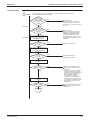
3.1
Startup Control
This control is used to equalize the pressure in the front and back of the compressor prior to the startup of the
compressor, thus reducing startup loads. Furthermore, the inverter is turned ON to charge the capacitor.
In addition, to avoid stresses to the compressor due to oil return or else after the startup, the following control is made
and the position of the four way valve is also determined. To position the four way valve, the master and slave units
simultaneously start up.
3.1.1 Startup Control in Cooling Operation
Thermostat ON
Startup control
Pressure equalization
control prior to startup
STEP1
STEP2
Compressor
0 Hz
52 Hz
+ OFF + OFF
124 Hz + OFF + OFF
+2 steps/20 sec.
(until Pc - Pe>0.39MPa is achieved)
Outdoor unit fan
STEP4
Ta<20°C: OFF
Ta≥20°C: STEP4
+1 step/15 sec. (when Pc>2.16MPa)
-1 step/15 sec. (when Pc<1.77MPa)
Four way valve (20S1)
Holds
OFF
OFF
Main motorized valve (EV1)
0 pls
480 pls
480 pls
Subcooling motorized valve
(EV2) (RXYQ8~)
0 pls
0 pls
0 pls
Hot gas bypass valve
(SVP)
OFF
OFF
OFF
Accumulator oil return valve
(SVO)
OFF
OFF
OFF
Injection (SVT) (RXYQ5P
model)
OFF
OFF
OFF
Ending conditions
A lapse of one minute
A lapse of 10 sec.
OR
• A lapse of 130 sec.
• Pc - Pe>0.39MPa
3.1.2 Startup Control in Heating Operation
Thermostat ON
Startup control
Pressure equalization
control prior to startup
STEP1
STEP2
Compressor
0 Hz
52 Hz
+ OFF + OFF
124 Hz + OFF + OFF
+2 steps/20 sec.
(until Pc - Pe>0.39MPa is achieved)
Outdoor unit fan
STEP4
STEP8
STEP8
Four way valve
Holds
ON
ON
Main motorized valve (EV1)
0 pls
0 pls
0 pls
Subcooling motorized valve
(EV2) (RXYQ8~)
0 pls
0 pls
0 pls
Hot gas bypass valve
(SVP)
OFF
OFF
OFF
Accumulator oil return valve
(SVO)
OFF
OFF
OFF
Injection (SVT) (RXYQ5P
model)
OFF
OFF
OFF
Ending conditions
A lapse of one minute
A lapse of 10 sec.
OR
Function
• A lapse of 130 sec.
• Pc>2.70MPa
• Pc-Pe>0.39MPa
29
Special Control
3.2
ESiEN09-06
Oil Return Operation
In order to prevent the compressor from running out of oil, the oil return operation is conducted to recover oil flown out
from the compressor to the system side.
3.2.1 Oil Return Operation in Cooling Operation
[Start conditions]
Referring to the set conditions for the following items, start the oil return operation in cooling.
• Cumulative oil feed rate
• Timer setting (Make this setting so as to start the oil return operation when the initial cumulative operating time
reaches two hours after power supply is turned ON and then every eight hours.)
Furthermore, the cumulative oil feed rate is computed from Tc, Te, and compressor loads.
Oil return preparation
operation
Outdoor unit actuator
Oil return operation
Post-oil-return operation
Compressor
5 HP: 52 Hz
(→ Low pressure constant
control)
Other model:
52 Hz + ON + ON
Take the current step as the
(→ Low pressure
upper limit.
constant control)
↓
Maintain number of
compressors in oil
return preparation
operation ON
Outdoor unit fan
Fan control (Normal cooling) Fan control (Normal cooling) Fan control (Normal cooling)
Four way valve
OFF
OFF
OFF
Main motorized valve (EV1)
480 pls
480 pls
480 pls
Subcooling motorized valve (EV2)
SH control
0 pls
0 pls
Hot gas bypass valve (SVP)
OFF
OFF
OFF
Accumulator oil return valve (SVO)
ON
ON
ON
Ending conditions
20 sec.
or
AHU actuator
Fan
30
• 3 min.
• Ts - Te<5°C
Same as the “oil return
operation” mode.
• 3 min.
• Pe<0.6MPa
• HTdi>110°C
or
Cooling oil return operation
Thermostat ON unit
ON
Stopping unit
OFF
Function
ESiEN09-06
Special Control
3.2.2 Oil Return Operation in Heating Operation
Oil return preparation
operation
Outdoor Unit Actuator
Oil return operation
Post-oil-return operation
Compressor
Upper limit control
176 Hz + ON + ON
124 Hz + OFF + OFF
2-steps increase/20sec.
till Pc - Pe>0.4 MPa
Outdoor unit fan
STEP7
or
STEP8
OFF
STEP8
Four way valve
ON
OFF
ON
Main motorized valve (EV1)
SH control → 480 pls
480 pls
55 pls
Subcooling motorized valve (EV2)
SH control
0 pls
0 pls
Hot gas bypass valve (SVP)
OFF
OFF
OFF
Accumulator oil return valve (SVO)
ON
ON
ON
Injection (SVT) (RXYQ5P model only)
OFF
OFF
OFF
Ending conditions
170 sec.
or
AHU actuator
Fan
Function
• 4 min.
• Ts - Te<5°C
or
• 10 sec.
• Pc - Pe>0.4MPa
Heating oil return operation
Thermostat ON unit
Field setting
Stopping unit
OFF
31
Special Control
3.3
ESiEN09-06
Defrosting Operation
To defrost the outdoor unit heat exchanger while in Evaporator, the defrost operation is conducted to recover the
heating capacity.
[Start conditions]
Referring to the set conditions for the following items, start the defrosting operation.
• Heat transfer coefficient of the outdoor unit heat exchanger
• Heat exchange temperature (Tb)
• Timer (Set to two hours at minimum.)
Furthermore, the heat transfer coefficient of the outdoor unit Evaporator is computed from Tc, Te, and compressor
loads.
Defrost preparation
operation
Outdoor unit actuator
Defrost operation
Post Defrost operation
Compressor
Upper limit control
176 Hz + ON + ON
124 Hz + OFF + OFF
2-steps increase/20sec.
till Pc - Pe>0.4 MPa
Outdoor unit fan
STEP7
or
STEP8
OFF
STEP8
Four way valve
ON
OFF
ON
Main motorized valve (EV1)
SH control → 480 pls
480 pls
55 pls
Subcooling motorized valve (EV2)
0 pls
0 pls
0 pls
Hot gas bypass valve (SVP)
OFF
OFF
OFF
Accumulator oil return valve (SVO)
ON
ON
ON
Injection (SVT) (RXYQ5P model only)
OFF
OFF
OFF
Ending conditions
170 sec.
or
• 10 min.
• Tb>11°C
or
• 10 sec.
• Pc - Pe>0.4MPa
* In the case of multi-outdoor-unit system,
Master unit: Performs the operations listed in the table above.
Slave units: Operating units perform the operations listed in the table above.
Non-operating units perform the operations listed in the table above from the Defrost operation.
(Non-operating unit stops during “Defrost preparation operation”.)
* Actuators are based on RXYQ14~18P.
AHU actuator
Fan
32
During defrost
Thermostat ON unit
Field setting
Stopping unit
OFF
Function
ESiEN09-06
3.4
Special Control
Pump-down Residual Operation
3.4.1 Pump-down Residual Operation in Cooling Operation
If the liquid refrigerant stays in the Evaporator at the startup of a compressor, this liquid refrigerant enters the
compressor, thus resulting in diluted oil in the compressor and then degraded lubrication performance.
Consequently, in order to recover the refrigerant in the Evaporator while the compressor stops, the pump-down residual
operation is conducted.
Actuator
Master unit operation
Compressor
124 Hz + OFF + OFF
Outdoor unit fan
Fan control
Four way valve
OFF
Main motorized valve (EV1)
480 pls
Subcooling motorized valve (EV2)
0 pls
Hot gas bypass valve (SVP)
OFF
Accumulator oil return valve (SVO)
ON
Ending conditions
5 min.
3.4.2 Pump-down Residual Operation in Heating Operation
Actuator
Master unit operation
Compressor
124 Hz + OFF + OFF
Outdoor unit fan
STEP7
Four way valve
ON
Main motorized valve (EV1)
0 pls
Subcooling motorized valve (EV2)
0 pls
Hot gas bypass valve (SVP)
OFF
Accumulator oil return valve (SVO)
ON
Ending conditions
3 min.
Function
33
Special Control
3.5
ESiEN09-06
Standby
3.5.1 Restart Standby
Used to forcedly stop the compressor for a period of 3 minutes, in order to prevent the frequent ON/OFF of the
compressor and equalize the pressure within the refrigerant system.
Actuator
Operation
Compressor
OFF
Outdoor unit fan
Ta>30°C: STEP4
Ta≤ 30°C: OFF
Four way valve
Holds
Main motorized valve (EV1)
0 pls
Subcooling motorized (EV2)
0 pls
Hot gas bypass valve (SVP)
OFF
Accumulator oil return valve (SVO)
OFF
Injection (SVT) (ERQ 125 A7W1B model)
OFF
Ending conditions
3 min.
3.5.2 Crankcase Heater Control
In order to prevent the refrigerant from melting in the compressor oil in the stopped mode, this mode is used to control
the crankcase heater.
Discharge pipe
temperature < 70°C
Crankcase heater
OFF
34
Discharge pipe
temperature > 75°C
Crankcase heater
ON
Function
ESiEN09-06
3.6
Special Control
Stopping Operation
3.6.1 When System is in Stop Mode (Normal operation stop)
This mode is used to define actuator operations when the system stops.
Actuator
Operation
Compressor
OFF
Outdoor unit fan
OFF
Four way valve
Holds
Main motorized valve (EV1)
0 pls
Subcooling motorized valve (EV2)
0 pls
Hot gas bypass valve (SVP)
OFF
Accumulator oil return valve (SVO)
OFF
Injection (SVT) (ERQ 125 model only)
OFF
Ending conditions
AHU thermostat is turned ON.
3.6.2 Stop due to Malfunction
In order to protect compressors, if any of the following items has an abnormal value, the system will make "stop with
thermostat OFF" and the malfunction will be determined according to the number of retry times.
Item
Judgment Criteria
Malfunction Code
1. Abnormal low pressure level
0.07MPa
E4
2. Abnormal high pressure level
4.0MPa
E3
3. Abnormal discharge pipe temperature level
135°C
F3
4. Abnormal power supply voltage
Reverse-phase power supply
U1
5. Abnormal inverter current level
16.1A: 260 sec.
L8
6. Abnormal radiator fin temperature level
93°C
L4
Function
35
Protection Control
ESiEN09-06
4. Protection Control
4.1
High Pressure Protection Control
This high pressure protection control is used to prevent the activation of protection devices due
to abnormal increase of high pressure and to protect compressors against the transient
increase of high pressure.
[In cooling operation]
High pressure not limited
Pc: HP pressure sensor detection
value for each outdoor unit
Pc>3.43MPa
INV upper limit frequency:
3-step down from current
compressor rps
INV upper limit rps = max
After 10 sec.
Pc>3.43MPa
Pc<3.24MPa
Current step maintained
Pc>3.55MPa
INV upper limit frequency:
1-step up from current
compressor frequency
After 15 sec.
After 10 sec.
Pc>3.64MPa
STD compressor
standby
High pressure standby
When occurring 3 times within 30 min.,
HPS is activated without high pressure
standby, thus outputting the
malfunction code “E3”.
[In heating operation]
High pressure not limited
Pc: HP pressure sensor detection
value for master unit
Pc>3.10MPa
Pc<2.9MPa
System load down 1 step
After 10 sec.
Pc>3.10MPa
Pc<3.0MPa
INV upper limit rps:
1-step up
Current step maintained
Pc>3.49MPa
After 60 sec.
Pc<2.52MPa
EV1 opening adjustment
(Reducing low pressure to
make high pressure lower.)
Pc>3.64MPa
High pressure standby
36
When occurring 3 times within 30 min.,
HPS is activated without high pressure
standby, thus outputting the
malfunction code “E3”.
Function
ESiEN09-06
4.2
Protection Control
Low Pressure Protection Control
This low pressure protection control is used to protect compressors against the transient
decrease of low pressure.
[In cooling operation]
Low pressure not limited
Pe<0.34MPa
Pe: LP pressure sensor detection
value for master unit
Pe>0.39MPa
Low pressure limited
Hot gas SVP = OFF
All STD compressors
stop.
Pe<0.15MPa
Pe>0.30MPa
Pe<0.25MPa
Hot gas SVP = ON
Unit: 52 Hz + OFF + OFF
Pe<0.07MPa
When occurring 4 times within 30 min.,
the malfunction code “E4” is output.
Low pressure standby
[In heating operation]
Pe: LP pressure sensor detection
value for outdoor unit
Low pressure not limited
Hot gas SVP = OFF
Pe<0.17MPa
INV upper limit frequency:
3-step down from current
compressor frequency
&
Pe >0.23 MPa
INV upper limit Hz = MAX
Pe<0.12MPa
Pe>0.17MPa
Hot gas SVP = ON
After 10 sec.
Pe<0.17MPa
Low pressure limited
Pe>0.20MPa
Pe<0.13MPa
After 15 sec.
INV upper limit frequency: 1-step
up from current compressor
frequency
After 10 sec.
52 Hz + OFF + OFF
Pe<0.07MPa
Low pressure standby
Function
When occurring 4 times within 30 min.,
the malfunction code “E4” is output.
37
Protection Control
4.3
ESiEN09-06
Discharge Pipe Protection Control
This discharge pipe protection control is used to protect the compressor internal temperature
against a malfunction or transient increase of discharge pipe temperature.
[INV compressor]
Normal operation
or
HTdi : Value of INV compressor discharge pipe
temperature (Tdi) compensated with
outdoor air temperature
Tp : Value of compressor port temperature
calculated by Tc and Te, and suction
superheated degree.
HTdi>115°C
Tp>135°C
INV upper limit frequency:
1-step down from current
compressor rps
&
HTdi<100°C
Tp<110°C
After 30 sec.
or
HTdi>115°C
Tp>135°C
&
HTdi>130°C
HTdi>120°C
or
for 90 sec.
or more.
Tp>130°C
HTdi<110°C
Tp<125°C
In discharge pipe temp.
protection control
After 20 sec.
ERQ 125 A7: 52 Hz
Other models:
INV62 Hz + OFF + OFF
or
INV upper limit frequency: 1-step up
from current compressor frequency
HTdi>135°C
HTdi>120°C for 10 min. or more.
Discharge pipe
temperature standby (for
a period of 10 minutes)
When occurring 3 times within 100 minutes,
the malfunction code “F3” is output.
[STD compressor]
HTds : Value of STD compressor discharge
pipe temperature (Tds) compensated
with outdoor air temperature
Tp : Value of compressor port temperature
calculated by Tc and Te, and suction
superheated degree.
or
• HTds>120°C continues for 5 min. or more.
• HTds>135°C
• Tp>135°C continues for 10 min. or more.
• Tp>145°C
Discharge pipe temp.
protection control not limited
Applicable STD
compressor stops.
After 10 min.
38
Function
ESiEN09-06
4.4
Protection Control
Inverter Protection Control
Inverter current protection control and inverter fin temperature control are performed to prevent
tripping due to a malfunction, or transient inverter overcurrent, and fin temperature increase.
[Inverter overcurrent protection control]
Nomal operation
Inverter current >14.7A
INV upper limit frequency: 1-step down
from current compressor frequency
&
Inverter current >14.7A
Inverter current <14.7A
INV upper limit frequency = max
Inverter current<14.7A continues
for 20 sec. or more.
INV upper limit frequency: 1-step up from
current compressor frequency
Under inverter current
protection control
Inverter current > 16.1A continues for 260 sec.
• When occurring 4 times within 60 min.,
the malfunction code “L8” is output.
Inverter current standby
[Inverter fin temperature control]
Nomal operation
Tfin>84°C
INV upper limit frequency: 1-step /
1 min down from current
compressor rps
Tfin<81°C
& INV upper limit rps = max
Tfin>84°C
Under fin temperature
protection control
Inverter fin temp.<81°C continues
for 3 min. or more.
INV upper limit frequency: 1-step / 1 min up
from current compressor frequency Interval
Tfin>93°C
Fin temp. standby
Function
• When occurring 4 times within 60 min.,
the malfunction code “L4” is output.
39
Protection Control
4.5
ESiEN09-06
STD Compressor Overload Protection
This control is used to prevent abnormal heating due to overcurrent to the compressor resulting
from failures of STD compressor such as locking.
STD compressor ON
*If the power supply is reset while in
CT detection current value>15.0A operation prohibition mode, the prohibition
timer will continue counting when the
power supply is turned ON.
Demand to operate.
STD compressor OFF for 30 min.*
When occurring 3 times within 90 minutes,
the malfunction code “E6” is output.
4.6
Injection Control (only for ERQ 125 A7W1B)
For transitional rise in discharge pipe temperature, have the liquid refrigerant flow into the
suction side to reduce the discharge pipe temperature for the compressor protection.
SVT = OFF
HTdi>112°C
HTdi<107°C
HTdi: Correction value of the discharge pipe
temperature on the INV compressor.
SVT = ON
40
Function
ESiEN09-06
Other Control
5. Other Control
5.1
Emergency Operation (only for ERQ 250 A7W1B)
If the compressor cannot operate, this control inhibits any applicable compressor or outdoor unit
from operating to perform emergency operation only with the operative compressor or outdoor
unit.
Caution
In order to disable the compressor operation due to a failure or else, be sure to do so
in emergency operation mode.
NEVER attempt to disconnect power supply wires from magnetic contactors or else.
(Doing so will operate compressors in combination that disables oil equalization
between the compressors, thus resulting in malfunctions of other normal
compressors.)
5.1.1 Restrictions for Emergency Operation
• In the case of system with 1 outdoor unit installed, only when thermostats of AHUs having a
capacity of 50% or more of the outdoor unit capacity turn ON, the emergency operation is
functional. (If the total capacity of units with thermostat ON is small, the outdoor unit cannot
operate.)
• If the emergency operation is set while the outdoor unit is in operation, the outdoor unit stops
once after pump-down residual operation (a maximum of 5 minutes elapsed).
Function
41
Other Control
ESiEN09-06
5.1.2 Principle
[Set the system to operation prohibition mode by compressor]
• In order to set an INV compressor to operation
LED display (7:ON 7:OFF 9:Blink)
prohibition mode, set No. 42 of Setting mode 2 to
H1P----H7P
"EMERGENCY OPERATION".
(Procedure)
(1) Press and hold the MODE button (BS1) for a
period of 5 seconds or more.
(2) Press the SET button (BS2) 42 times.
(3) Press the RETURN button (BS3) once.
(4) Press the SET button (BS2) once.
(5) Press the RETURN button (BS3) twice.
(6) Press the MODE button (BS1) once.
• In order to set STD1 compressor to operation
prohibition mode, set No. 19 of Setting mode 2 to
"STD1 OPERATION PROHIBITION". (ERQ 250
A7W1B)
(Procedure)
(1) Press and hold the MODE button (BS1) for a
period of 5 seconds or more.
(2) Press the SET button (BS2) 19 times.
(3) Press the RETURN button (BS3) once.
(4) Press the SET button (BS2) once.
(5) Press the RETURN button (BS3) twice.
(6) Press the MODE button (BS1) once.
42
7777777
777777
777
777
777
7 (Factory set)
77777
77777
79
7777
7777
797
7777777
777777
7777777
77
7777
LED display (7:ON 7:OFF 9:Blink)
H1P----H7P
7777777
777777
77
7777
7777
777777 (Factory set)
7777777
777797
77777
777777
7777777
7777777
77
7777
Function
ESiEN09-06
5.2
Other Control
Demand Operation
In order to save the power consumption, the capacity of outdoor unit is saved with control
forcibly by using “Demand 1 Setting” or “Demand 2 Setting”.
To operate the unit with this mode, additional setting of “Continuous Demand Setting” or
external input by external control adapter is required.
Set item
Demand 1
Demand 2
5.3
Condition
Mode 1
Mode 2
Mode 3
⎯
Content
The compressor operates at approx. 60% or less of rating.
The compressor operates at approx. 70% or less of rating.
The compressor operates at approx. 80% or less of rating.
The compressor operates at approx. 40% or less of rating.
Heating Operation Prohibition
Heating operation is prohibited above 24°C ambient temperature.
Function
43
Outline of Control
ESiEN09-06
6. Outline of Control
6.1
Thermostat Sensor in Remote Control (only for Zcontrol)
Temperature is controlled by both the thermostat sensor in remote control and air suction
thermostat in the AHU. (This is however limited to when the field setting for the thermostat
sensor in remote control is set to “Use.”)
Cooling
If there is a significant difference in the preset temperature and the suction temperature, fine
adjustment control is carried out using a body thermostat sensor, or using the sensor in the
remote control near the position of the user when the suction temperature is near the preset
temperature.
°C
Preset temperature
(Ts)
°C
Suction temperature (TH1)
Range in which thermostat sensor
in remote control can be used
Range in which body
thermostat sensor can be used
Differential
(VG003)
Ex: When cooling
Assuming the preset temperature in the figure above is 24°C, and the suction
temperature has changed from 18°C to 30°C (A → F):
Body thermostat sensor is used for temperatures from 18°C to 23°C (A → C).
Remote control thermostat sensor is used for temperatures from 23°C to 27°C (C → E).
Body thermostat sensor is used for temperatures from 27°C to 30°C (E → F).
And, assuming suction temperature has changed from 30°C to 18°C (F → A):
Body thermostat sensor is used for temperatures from 30°C to 25°C (F → D).
Remote control thermostat sensor is used for temperatures from 25°C to 21°C (D → B).
Body thermostat sensor is used for temperatures from 21°C to 18°C (B → A).
44
Function
ESiEN09-06
Outline of Control
Heating
When heating, the hot air rises to the top of the room, resulting in the temperature being lower
near the floor where the occupants are. When controlling by body thermostat sensor only, the
unit may therefore be turned off by the thermostat before the lower part of the room reaches the
preset temperature. The temperature can be controlled so the lower part of the room where the
occupants are doesn’t become cold by widening the range in which thermostat sensor in remote
control can be used so that suction temperature is higher than the preset temperature.
°C
Preset temperature
(Ts)
°C
Suction temperature (TH1)
Range in which thermostat sensor
in remote control can be used
Range in which body
thermostat sensor can
be used
Differential
(V2769)
Ex: When heating Assuming the preset temperature in the figure above is 24°C, and
the suction temperature has changed from 18°C to 28°C (A → D):
Body thermostat sensor is used for temperatures from 18°C to 25°C (A → C).
Remote control thermostat sensor is used for temperatures from 25°C to 28°C (C → D).
And, assuming suction temperature has changed from 28°C to 18°C (D → A):
Remote control thermostat sensor is used for temperatures from 28°C to 23°C (D → B).
Body thermostat sensor is used for temperatures from 23°C to 18°C (B → A).
6.2
Hot Start Control (In Heating Operation Only)
At startup with thermostat ON or after the completion of defrosting in heating operation, the AHU
fan is controlled to prevent cold air from blasting out and ensure startup capacity.
[Detail of operation]
For more information refer to the chapter “Field Setting”.
Function
45
Outline of Control
6.3
ESiEN09-06
Freeze Prevention
Freeze
Prevention by Off
Cycle (AHU)
When the temperature detected by liquid pipe temperature thermistor (R2T) of the AHU heat
exchanger drops too low, the unit enters freeze prevention operation in accordance with the
following conditions, and is also set in accordance with the conditions given below.
Conditions for starting freeze prevention: Temperature is -1°C or less for total of 40 min., or
temperature is -5°C or less for total of 10 min.
Conditions for stopping freeze prevention: Temperature is +7°C or more for 10 min.
continuously
Ex: Case where temperature is -5°C or less for total of 10 min.
10 min.
Freeze prevention operation
10 min.
46
Forced OFF by thermostat
Function
ESiEN09-06
6.4
Outline of Control
Low Outdoor Air Temperature Protection Control
Objective
In cooling (or fan operation) or heating, if outdoor air is low in temperature, stop the fan forcibly.
Details
[Cooling and fan operation]
Turn OFF the fan for a period of 60 minutes at a suction temperature of 5°C or lower.
In order to monitor the outdoor air temperature, however, turn ON the fan for a period of one
minute and turn OFF the fan again at a temperature of 5°C or lower after the said timer
completes the operative period.
Reset the 60-minute timer when the fan stops running.
[Heating]
Turn OFF the fan for a period of 60 minutes at a suction temperature of –5°C or lower.
In order to monitor the outdoor air temperature, however, turn ON the fan for a period of one
minute and turn OFF the fan again at a temperature of –5°C or lower after the said timer
completes the operative period.
Reset the 60-minute timer when the fan stops running.
* The thermostat will not turn ON in one minute due to the temperature while the fan stops.
This control shall be disabled at test run both in cooling and heating. (The test run shall be
conducted first.)
Function
47
Outline of Control
48
ESiEN09-06
Function
ESiEN09-06
Part 5
Control Box EKEQ - CBV3
1. Different Systems with their Control Boxes...........................................50
1.1 System A: PAIR......................................................................................50
1.2 System B: MULTI ...................................................................................52
2. X, Y, Z Control.......................................................................................55
2.1 X-Control ................................................................................................55
2.2 Y-Control ................................................................................................56
2.3 Z-Control ................................................................................................57
3. Wiring Diagram of Control Box..............................................................58
3.1 D-box......................................................................................................58
3.2 F-box ......................................................................................................59
4. Attention Points .....................................................................................60
5. System A: EKEQF & EKEQD-box: Installation and Operation Manual.61
6. System B: EKEQM-box: Installation and Operation Manual .................76
Control Box EKEQ - CBV3
49
Different Systems with their Control Boxes
ESiEN09-06
1. Different Systems with their Control Boxes
For steering a field supply AHU by an outdoor inverter heat pump, 2 systems can be used:
System A: PAIR application (ERQ-outdoor)
System B: MULTI application (VRV-outdoor)
1.1
System A: PAIR
System A = PAIR : ERQ + EXV-Kit
ERQ
EKEQDCB
Or
EKEQFCB
AHU
EKEXV-kit
Field supply
Pair application here means 1 outdoor unit + 1 AHU.
In pair application, there’s the choice between 2 control boxes: EKEQD or EKEQF.
50
Control Box EKEQ - CBV3
Dedicated power supply
1~/230V/50Hz (4,5,6 Hp)
(only in combination with
EKEQFCB & X-control)
cool/heat
selection
Remocon connection
EKEQFCB => BRC1D = service tool
EKEQDCB => BRC1D = required option
* 2 types depending on
control type
DDC
0-10V DC
Capacity step
control
Communication
2 lines (F1,F2)
EKEQFCB / EKEQDCB
(Pair application only)
power supply
(depend on AHU)
power supply (depend
on Controller)
distances:
A,B,C,D,E,F : see below
remarks:
(*1) Compressor running
Can be both on air or water control
(Third party Air handling unit)
AHU
Liquid pipe
Gas pipe
Control
H/E thermistor 2
H/E thermistor 1
Air Thermistor
(only needed for
control type Z)
(Field supplied Digital controller)
DDC has temperature sensor for
target (e.g. air discharge temp.)
ON/OFF
Attention:
Need software block to prevent
VRV AHUs to be connected on
ERX condensing unit.
power supply
(1~/230V/50Hz)
Fan status
ERQ
(Pair application only)
EXV - Kit
Error Status
Liquid pipe
System A: ERQ - Unit + EXV-kit
Unit ON/OFF (*1)
Control Box EKEQ - CBV3
Defrost status
ESiEN09-06
Different Systems with their Control Boxes
51
Different Systems with their Control Boxes
ESiEN09-06
Allowable lengths and heights
System A:
EXV-kit
Control Box
(D or F - type)
ERQ
AHU
DDC
Allowable height:
AHU
≤ 5m
Total system: ≤ 30 m
EXV-kit
(outdoor unit can be above
or below the AHU)
outdoor
Piping
Communication
A
B
C
D
E
F
length: 5 < A ≤ 50 m
length: ≤ 5 m
≤ 100 m
≤ 20 m
≤ 20 m
depend on
DDC
125
ERQ
3 phase
200
250
1.2
System B: MULTI
Only for combining VRV + AHU + indoors. No ERQ!
System B = MULTI (suction control) : VRV + EXV-Kit
VRV
H/P
EKEQMCB
AHU
EKEXV-KIT
Field supply
EKEQMCB
AHU
EKEXV-KIT
VRV indoor 1
VRV indoor n
Qty of
EKEXV - kits
is limited by
connection
ratio.
Multi application with VRV means the ability to combine 1 outdoor unit + several AHU, as well
as VRV indoors (minimum 1 is required). The required control box for this application is
EKEQM.
52
Control Box EKEQ - CBV3
Control Box EKEQ - CBV3
H/P
VRV
Dedicated power supply
1~/230V/50Hz
Or
3~/400V/50Hz
Communication
2 lines (F1,F2)
Liquid pipe
Gas pipe
Gas pipe
Gas pipe
EXV - kit 1
EXV - kit n
Remocon connection
(required option)
(multi application only)
EKEQMCB
power supply
(1~/230V/50Hz)
EKEQMCB n
VRV AHU 1
VRV AHU n
System B: VRV + EXV-kit
H/E thermistor 2
H/E thermistor 1
Air thermistor
(only needed for
control type Z)
Liquid pipe
AHU n
Can be both on air or
water control.
(Third party Air handling
unit)
AHU
distances:
A,B,C,D,E : see below
power supply
(depend on AHU)
Number of EXV-kits (n) which can be connected is
determined by connection ratio or max number of AHUs
on VRV-system (EXV-kit B is 1 if AHUs.)
ESiEN09-06
Different Systems with their Control Boxes
53
Different Systems with their Control Boxes
ESiEN09-06
Allowable lengths and heights
System B:
EXV-kit
VRV
H/P & VRV
Control Box
(M-type)
AHU
KIT n
Indoor 1
Indoor n
Allowable height:
AHU1
≤ 5m
EXV-kit 1
AHU n
Total system: ≤ 40 m
≤ 15 m
(outdoor unit can be above
or below the AHU)
≤ 5m
EXV-kit n
outdoor
Piping
A+B
VRV
consider same as 1
indoor unit
Communication
B
C
D
E
length: ≤ 5 m
follow std.
VRV wiring
length policy
≤ 50 m
≤ 50 m
Connection ratio: 50-110%
54
Control Box EKEQ - CBV3
ESiEN09-06
X, Y, Z Control
2. X, Y, Z Control
The D, F, M boxes have different types of control, giving the ability to control different
temperatures (Td, Ts, Tr, Te or Tc).
Schematic:
AHU
Te
Ts
Td
Tr
DDC
ROOM
Legend:
Td
Ts
Tr
Discharge air control
Suction air control
Room air control
Evaporating temperature control
Condensing temperature control
Air handling unit
Digital controller
Te
Tc
AHU
DDC
EKEQD: Z-control
EKEQF: X, Y-control
EKEQM: Z-control
2.1
X-Control
Control of air temperature (Td, Ts or Tr) by means of an external device (DDC controller, 0-10V
control).
output
10V
Tmeasured
5V
0V
-∆T Tset +∆
∆T
DDC
0~10 V
Tset
∆T = Tset - Tmeasured
Tmeasured = Td, Ts or Tr
Components for control:
DDC (field supply)
Air thermistor (field supply)
BRC1D (only for servicing)
++
--
Possibility for Td control
Flexibility in applications
Higher cost (DDC needed)
In case of X-control, a DDC-controller is needed to operate the unit. This DDC-controller is field
supply but in order to connect it to our ERQ-system, it is required that it emits a 0-10 VDC signal
towards the control box.
Control Box EKEQ - CBV3
55
X, Y, Z Control
ESiEN09-06
2.1.1 Different levels
0-10V
DDC
level 1
level 2
level 3
level 4
level 5
Control Box
X-control
Inside the control box, this 0-10 VDC signal is converted into a voltage level.
The output voltage increase gives the voltage at which the level increases.
The output voltage decrease gives the voltage at which the level decreases.
Output level
DDC
Level 1
Level 2
1.8
-->
1.2
<--
Output voltage increasing
Output voltage decreasing
Level 3
3.8
-->
3.2
<--
Level 4
6.8
-->
6.2
<--
Level 5
8.8
-->
8.2
<--
Example:
Room temperature = 20°C, set temperature = 25°C. Heating operation: DDC controller,
calculates the difference and sends a 3 VDC signal (fictive value) to the control box. This is
between 1,8 and 3,8 so in level 2. When the room temperature rises to 23°C, the DDC controller
detects a smaller temperature difference and will send out a higher signal, ex. 5 VDC. The
output voltage has increased so you have to use the highest line, indicating that you are now in
level 3. When the window is opened, the room temperature drops and the difference with the set
temperature is higher. The DDC sends a 1 V signal. According to the “output voltage
decreasing” line, we are now in level 1.
2.1.2 Refrigerant target temperature
refrigerant
target temp.
0-10V
DDC
Control Box
X-control
level 1
level 2
level 3
level 4
level 5
+2
+1
0
-1
-2
cooling heating
Te+2
Te+1
Te
Te-1
Te-2
Tc+2
Tc+1
Tc
Tc-1
Tc-2
Example, continued:
3 VDC = level 2, thus meaning an increase of the refrigerant target temperature. In heating
mode, this means Tc + 1°C. Logically, the room temperature will rise so at the next signal, we
are in level 3, where Tc is kept even.
T < 0
T = 0
T > 0
level 1 + level 2
level 3
level 4 + level 5
Cooling
DDC asks less capacity
no change
DDC asks more capacity
Heating
DDC asks more capacity
no change
DDC asks less capacity
T = room temp. - set temp.
2.2
Y-Control
Control of evaporating and condensing temperature (Te and Tc) by Daikin control (no DDC
needed).
Fixed Te or Tc
Te = user setting: -3 ~ 10°C
Tc = user setting: 43 ~ 49°C
56
Control Box EKEQ - CBV3
ESiEN09-06
X, Y, Z Control
Components for control:
BRC1D (only for servicing)
++
--
Low cost
No BRC needed
No air temperature control
With Y-control, there is no external input to change Te/Tc value. Their values can only be
changed by local setup with a Daikin remote control (during installation). We refer to the chapter
“Field Setting” for further information.
2.3
Z-Control
Control of air temperature (Ts or Tr) by Daikin control (no DDC needed).
Components for control:
Air thermistor (Daikin)
BRC1D (Daikin)
KRP4A (Daikin option, remote on/off)
++
--
Item
1
28
29
30
31
32
33
34
35
36
37
Control Box EKEQ - CBV3
Low cost
BRC needed
No possibility for Td control
Name
On/off button
Inspection/test operation button
Programming button
Schedule timer button
Time adjust buttons
Temperature adjust buttons
Operation change/min-max button
Setpoint/limit button
Fan speed button
Air flow direction adjust button
Air filter cleaning time icon reset button
User
Customer
Installer
Installer
Customer
Customer
Customer
Customer
Customer
Customer
Customer
Customer
Z
0
0
0
0
0
0
0
0
x
x
x
BP
0
0
0
0
0
0
0
0
0
x
0
M
0
0
0
0
0
0
0
0
x
x
x
BM
0
0
0
0
0
0
0
0
x
x
x
57
: Printed circuit board
: Printed circuit board (Option KRP4)
: Fuse (250V, F5A) (A1P)
: Field fuse
: Light emitting diode (service monitor green)
: Magnetic relay
: Magnetic relay (Fan) AC
: Earth leakage breaker
: Capacity adapter
: Thermistor (Air)
: Thermistor (Liquid)
: Thermistor (Gas)
: Transformer (220V/21.8V)
: Terminal block
: Terminal block
: Thermistor Liquid
: Thermistor Gas
: Thermistor Air
: Expansion valve
: Output: Fan ON/OFF
: Communication remote control
: Communication outdoor
: Input: ON/OFF
: Electronic expansion valve
58
Position in switch box
: Field wiring
: Live
: Neutral
: Connector
: Wire clamp
: Protective earth (Screw)
: Seperate component
: Optional accessory
Wired remote control
Outdoor
3.1
1 Use copper conductors only.
2 BLK: Black / WHT: White / RED: Red / BLU: Blue /
BRN: Brown / GRY: Grey / GRN: Green / ORG: Orange /
PINK: Pink / YLW: Yellow
A1P
A2P
F1U
F3U
HAP
K1R
K4R
Q1DI
R7
R1T
R2T
R3T
T1R
X1M
X3M
X1M-R1/R2
X1M-R3/R4
X1M-R5/R6
X1M-Y1~6
X1M-C1/C2
X1M-P1/P2
X1M-F1/F2
X1M-T1/T2
Y1E
~50Hz
230V
Wiring Diagram of Control Box
ESiEN09-06
3. Wiring Diagram of Control Box
D-box
Control Box EKEQ - CBV3
: Printed circuit board
: Printed circuit board (for voltage conversion)
: Printed circuit board (Power supply)
: Fuse (250V, F5A) (A1P)
: Fuse (250V, T1A) (A3P)
: Field fuse
: Light emitting diode (service monitor green)
: Magnetic relay (error status) AC
: Magnetic relay (Operation / Compressor ON/OFF) AC
: Magnetic relay (Fan) AC
: Magnetic relay (Defrost signal) DC
: Magnetic relay
: Earth leakage breaker
: Resistance (DC 120 OHM)
: Capacity adapter
: Thermistor (Liquid)
: Thermistor (Gas)
: Transformer (220V/21.8V)
: Terminal block
: Terminal block
: Terminal block
: Electronic expansion valve
: Thermistor Liquid
: Thermistor Gas
: Expansion valve
: Communication remote control
: Output: error status
: Output: Operation / Compressor ON/OFF
: Input: 0-10V DC capacity control
: Output: Fan ON/OFF
: Output: Defrost signal
: Communication outdoor
: Input: ON/OFF
Control Box EKEQ - CBV3
Position in switch box
: Field wiring
: Live
: Neutral
: Connector
: Wire clamp
: Protective earth (Screw)
: Seperate component
: Optional accessory
Wired remote control
Outdoor
Only for 0-10V input
3.2
1 Use copper conductors only.
2 BLK: Black / WHT: White / RED: Red / BLU: Blue /
BRN: Brown / GRY: Grey / GRN: Green / ORG: Orange /
PINK: Pink / YLW: Yellow
A1P
A2P
A3P
F1U
F2U
F3U
HAP
K2R
K3R
K4R
K5R
K1R, KAR, KPR
Q1DI
R5
R6
R2T
R3T
T1R
X1M
X2M
X3M
X1E
X1M-R1/R2
X1M-R3/R4
X1M-Y1~6
X2M-P1/P2
X2M-C1/C2
X2M-C3/C4
X2M-C5/C6
X1M-C7/C8
X1M-C9/C10
X2M-F1/F2
X2M-T1/T2
~50Hz
230V
ESiEN09-06
Wiring Diagram of Control Box
F-box
59
Attention Points
ESiEN09-06
4. Attention Points
Do not forget to place the capacity setting adapter. Otherwise, you’ll get UA or PJ error.
All capacity setting adapters are delivered with the control box.
Polarity of the C5/C6-contact (F-box, X-control) C5 = ”-”, C6 = ”+”
60
Control Box EKEQ - CBV3
ESiEN09-06
System A: EKEQF & EKEQD-box: Installation and Operation Manual
5. System A: EKEQF & EKEQD-box: Installation and
Operation Manual
Control Box EKEQ - CBV3
61
INSTALLATION AND
OPERATION MANUAL
Option kit for combination of Daikin condensing units with
field supplied air handling units
EKEQFCBV3
EKEQDCBV3
Installation and operation manual
Option kit for combination of Daikin condensing units
with field supplied air handling units
English
Installations- und Bedienungsanleitung
Erweiterungsbausatz für die Verbindung von Daikin-Verflüssigern mit
bauseitigen Luftbehandlungsgeräten
Deutsch
Manuel d'installation et d'utilisation
Kit d’options pour combinaison de groupes condenseur Daikin
et unités de traitement de l’air non fournies
Français
Montagehandleiding en gebruiksaanwijzing
Optiekit voor combinatie van condensorunits van Daikin
met lokaal geleverde luchtbehandelingsunits
Nederlands
Manual de instalación y operación
Kit de opciones para la combinación de unidades de condensación
Daikin con unidades de tratamiento de aire suministradas
Español
Manuale di installazione e d'uso
Kit opzioni per la combinazione di unità di condensazione Daikin
con unità per il trattamento dell’aria non in dotazione
Italiano
Manual de instalação e de funcionamento
Kit de opções para combinação de unidades de condensação Daikin
com unidades de tratamento de ar existentes no local
Portugues
Daikin Instrukcja montau i instrukcja obs#ugi
Zestaw opcji dla agregatów skraplaj$cych Daikin
w konfiguracji z centralami klimatyzacyjnymi dostarczanymi osobno
polski
1
2
3
6
5
1
3
6
2
5
1
2
4
7
10 9
11
8
7
13
12 9
EKEQFCBV3
1
8
13
EKEQDCBV3
2
4
3
2
FAN
L
expansion valve
gas
liquid
remocon outdoor ON/OFF
defrost
N C7 C8 Y1 Y2 Y3 Y4 Y5 Y6 R3 R4 R1 R2 C9 C10
error
operation
4
11 8 9 10 5
7
3
5
1
X24A
6
0-10 V
P1 P2 F1 F2 T1 T2 C1 C2 C3 C4 C5 C6
H1
N
Y1 Y2 Y3 Y4 Y5 Y6
H2
H3
R2T
L
R3T
F1 F2
0 +10
H4 H4 H7
H7
H5
H6
H1 H2 H4
H3 H7
EKEQFCBV3
3
H5 H6
EKEQFCBV3
4
5
6
expansion valve
L
gas
liquid
air
remocon outdoor ON/OFF
N Y1 Y2 Y3 Y4 Y5 Y6 R3 R4 R1 R2 R5 R6 P1 P2 F1 F2 T1 T2
FAN
C1 C2
2
4 10
5
3
1
X24A
12
H1
Y1 Y2 Y3 Y4 Y5 Y6
H2
R1T
N
R2T
L
R3T
F1 F2
H5
H3 H4 H4
H8
H6
H1 H2 H4
H3 H5
H7
5
EKEQDCBV3
6
H6 H7 H8
EKEQDCBV3
EKEQFCBV3
EKEQDCBV3
CONTENTS
Option kit for combination of Daikin condensing units
with field supplied air handling units
Page
Installation and
operation manual
INTRODUCTION
Introduction ............................................................. 64
■
Do only use this system in combination with a field
supplied air handling unit. Do not connect this system
to other indoor units.
■
Only optional controls as listed in the optional
accessories list can be used.
Installation ............................................................... 65
Accessories ............................................................... 65
Name and function of parts ....................................... 65
Before installation...................................................... 65
We distinguish 2 different control boxes, each with its own application
and installation requirements.
Selecting the installation site ..................................... 66
■
■ Operation with 0–10 V input to control the capacity
An external controller is needed to control the capacity. For
details of the necessary functions of the external controller
refer to paragraph "Operation with 0–10 V capacity
Valve kit installation ................................................... 67
Installation of the electrical control box ..................... 68
Electric wiring work ................................................... 68
control". It can be used to control the room temperature or
air discharge temperature.
Installation of thermistors .......................................... 71
Refrigerant piping work ............................................. 72
■ Operation with fixed Te/Tc temperature control
This system operates on a fixed evaporating temperature.
Test operation............................................................ 72
■
EKEQDCB control box
The system will operate as a standard indoor unit to control the
room temperature. This system does not require a specific
external controller.
■
Do NOT connect the system to DIII-net devices:
Operation and maintenance ................................... 72
What to do before operation...................................... 72
Operation and display signals ................................... 74
EKEQFCB control box (2 possible operation modes)
Troubleshooting......................................................... 74
Maintenance.............................................................. 75
Disposal requirements............................................... 75
This could result in malfunction or breakdown of the total
system.
READ THESE INSTRUCTIONS CAREFULLY BEFORE
INSTALLATION AND OPERATION.
IMPROPER INSTALLATION OR ATTACHMENT OF
EQUIPMENT OR ACCESSORIES COULD RESULT IN
ELECTRIC SHOCK, SHORT-CIRCUIT, LEAKS, FIRE OR
OTHER DAMAGE TO THE EQUIPMENT. BE SURE ONLY
TO USE ACCESSORIES MADE BY DAIKIN WHICH ARE
SPECIFICALLY DESIGNED FOR USE WITH THE
EQUIPMENT AND HAVE THEM INSTALLED BY A
PROFESSIONAL.
IF UNSURE OF INSTALLATION PROCEDURES OR USE,
ALWAYS CONTACT YOUR DAIKIN DEALER FOR
ADVICE AND INFORMATION.
■
This equipment is not designed for year-round cooling
applications with low indoor humidity conditions, such as
Electronic Data Processing rooms.
■
This appliance is not intended for use by persons, including
children, with reduced physical, sensory or mental capabilities,
or lack of experience and knowledge, unless they have been
given supervision or instruction concerning use of the appliance
by a person responsible for their safety.
Children should be supervised to ensure that they do not play
with the appliance.
The English text is the original instruction. Other languages are
translations of the original instructions.
Installation and operation manual
64
EKEQFCBV3 + EKEQDCBV3
Option kit for combination of Daikin condensing units
with field supplied air handling units
4PW52446-1
INSTALLATION
■
■
■
NAME AND FUNCTION OF PARTS (See figure 1
and
figure 2)
For installation of the air handling unit, refer to the air handling
unit installation manual.
Parts and components
Never operate the air conditioner with the discharge pipe
thermistor (R3T), suction pipe thermistor (R2T) and pressure
sensors (S1NPH, S1NPL) removed. Such operation may burn
out the compressor.
The equipment is not intended for use in a potentially explosive
atmosphere.
1
Outdoor unit
2
Control box (EKEQFCB / EKEQDCB)
3
Air handling unit (field supply)
4
Controller (field supply)
5
Field piping (field supply)
6
Expansion valve kit
Wiring connections
ACCESSORIES
EKEQFCB
EKEQDCB
—
1
Thermistor (R1T)
Thermistor (R3T/R2T)
(2.5 m cable)
2
Insulation sheet
2
Rubber sheet
2
Wire to wire splice
4
7
Outdoor unit power supply
8
Control box wiring
(Power supply and communication between control box and
outdoor unit)
9
Air handling unit thermistors
10
Communication between controller and control box
11
Power supply and control wiring for air handling unit and controller
(power supply is separate from the outdoor unit)
12
Air thermistor control for air handling unit
13
Remote control (
= for service only)
6
BEFORE INSTALLATION
Installation and
operation manual
1
Cautions for selection of the air handling unit
Screw nut
7
8
See table below for applicable units.
Tie wrap
6
Capacity setting
adapter
7
Stopper (closing cup)
2
Select the air handling unit (field supply) according to the technical
data and limitations mentioned below.
—
The design pressure of the air handling unit is at least 40 bar.
Lifetime of the outdoor unit, operation range or operation reliability
may be influenced if you neglect these limitations.
Obligatory accessory
Limits for outdoor unit (expansion valve kit)
EKEQFCB
Expansion valve kit
EKEQDCB
Outdoor
unit (class)
EKEXV
Refer to chapter "Valve kit installation" on page 67 for installation
instructions.
EKEXV kit
100
EKEXV63~125
200
EKEXV100~250
125
EKEXV63~140
250
EKEXV125~250
140
EKEXV80~140
Depending on the heat exchanger, a connectable EKEXV (expansion
valve kit) must be selected to these limitations.
Optional accessories
EKEQFCB
Remote control
Outdoor
unit (class)
EKEXV kit
1(*)
EKEQDCB
1
(*) Not required for operation, only useful accessory tool for service and installation.
EKEXV
class
Allowed heat exchanger
volume (dm3)
Allowed heat exchanger
capacity (kW)
Minimum
Maximum
Minimum
Maximum
63
1.66
2.08
6.3
7.8
80
2.09
2.64
7.9
9.9
100
2.65
3.30
10.0
12.3
125
3.31
4.12
12.4
15.4
140
4.13
4.62
15.5
17.6
200
4.63
6.60
17.7
24.6
250
6.61
8.25
24.7
30.8
Saturated suction temperature (SST) = 6°C, SH (superheat) = 5 K,
air temperature = 27°C DB / 19°C WB.
1
Selecting the condensing unit
Depending on necessary capacity of the combination an outdoor
unit needs to be selected (see "Engineering databook" for
capacity).
■ Each outdoor unit can be connected to a range of air
handling units.
■ The range is determined by the allowed expansion valve kits.
EKEQFCBV3 + EKEQDCBV3
Option kit for combination of Daikin condensing units
with field supplied air handling units
4PW52446-1
Installation and operation manual
65
2
SELECTING THE INSTALLATION SITE
Selecting the expansion valve
The corresponding expansion valve needs to be selected for
your air handling unit. Select the expansion valve according to
the above limitations.
NOTE
■
If conflicting result, capacity selection has
priority over volume.
Select an installation site where the following conditions are fulfilled
and that meets your customer’s approval.
■
The expansion valve is an electronic type, it is
controlled by the thermistors that are added in
the circuit. Each expansion valve can control a
range of air handling units sizes.
■
The option boxes (expansion valve and electrical control box)
can be installed inside and outside).
■
Do not install the option boxes in or on the outdoor unit.
■
Do not put the option boxes in direct sunlight. Direct sunlight will
increase the temperature inside the option boxes and may
reduce its lifetime and influence its operation.
■
Choose a flat and strong mounting surface.
■
Operating temperature of the control box is between –10°C and
40°C.
■
Keep the space in front of the boxes free for future maintenance.
■
Keep air handling unit, power supply wiring and transmission
wiring at least 1 m away from televisions and radios. This is to
prevent image interference and noise in those electrical
appliances. (Noise may be generated depending on the
conditions under which the electric wave is generated, even if
1 m is kept.)
■
Make sure the control box is installed horizontally. Screw nuts
position must be downwards.
■
The selected air handling unit must be
designed for R410A.
■
Extraneous substances (including mineral oils
or moisture) must be prevented from getting
mixed into the system.
■
3
This is a class A product. In a domestic environment this product may
cause radio interference in which case the user may be required to
take adequate measures.
SST: saturated suction temperature at exit of
air handling unit.
Selecting the capacity setting adapter (see accessories)
■ The corresponding capacity setting adapter needs to be
selected depending on the expansion valve.
■ Connect the correct selected capacity setting adapter to
X24A (A1P). (See figure 4 and figure 6)
EKEXV kit
Capacity
setting adapter
label
(indication)
63
EKEXV kit
Capacity
setting adapter
label
(indication)
J71
140
J160
80
J90
200
J224
100
J112
250
J280
125
J140
For the following items, take special care during construction
and check after installation is finished
Precautions
Do not install or operate the unit in rooms mentioned below.
■
Where mineral oil, like cutting oil is present.
■
Where the air contains high levels of salt such as air near the
ocean.
■
Where sulphurous gas is present such as that in areas of hot
spring.
■
In vehicles or vessels.
Tick ✓
when
checked
■
Where voltage fluctuates a lot such as that in factories.
■
Where high concentration of vapor or spray are present.
■
Are the thermistors fixed firmly?
Thermistor may come loose.
■
Where machines
present.
■
Is the freeze-up setting done correctly?
The air handling unit may freeze up.
■
Where acidic or alkaline vapor is present.
■
The option boxes must be installed with entrances downward.
■
Is the control box fixed firmly?
The unit may drop, vibrate or make noise.
■
Do electrical connections comply with specifications?
The unit may malfunction or components may burn out.
■
Are wiring and piping correct?
The unit may malfunction or components may burn out.
■
Is the unit safely grounded?
Dangerous at electric leakage.
Installation and operation manual
66
generating
electromagnetic
waves
are
EKEQFCBV3 + EKEQDCBV3
Option kit for combination of Daikin condensing units
with field supplied air handling units
4PW52446-1
VALVE KIT INSTALLATION
Cautions for brazing
Mechanical installation
■
Be sure to carry out a nitrogen blow when brazing.
Brazing without carrying out nitrogen replacement or releasing
nitrogen into the piping will create large quantities of oxidized
film on the inside of the pipes, adversely affecting valves and
compressors in the refrigerating system and preventing normal
operation.
■
When brazing while inserting nitrogen into the piping, nitrogen
must be set to 0.02 MPa with a pressure-reducing valve (=just
enough so that it can be felt on the skin).
1
Remove the valve kit box cover by unscrewing 4x M5.
2
Drill 4 holes on correct position (measurements as indicated in
figure below) and fix the valve kit box securely with 4 screws
through the provided holes Ø9 mm.
NOTE
■
Make sure that the expansion valve is installed
vertically.
■
Make sure there is enough free space for future
maintenance.
1
2
Brazing work
3
4
5
6
6
For details, see manual of the outdoor unit.
3
Prepare the inlet/outlet field piping just in front of the connection
(do not braze yet).
192.5 mm
■
1
Refrigerant piping
2
Part to be brazed
3
Taping
4
Hands valve
5
Pressure-reducing valve
6
Nitrogen
For details, see manual of the outdoor unit.
Electrical work
340 mm
C
B
1
Open the electrical box cover (A).
2
Push out ONLY the second lower wire intake hole (B) from
inside to outside. Do not damage the membrane.
3
Pass valve cable (with wires Y1 ... Y6) from the control box
through that membrane wire intake hole and connect the cable
wires into the terminal connector (C) following instructions as
described in step 4. Route the cable out of the valve kit box
according to figure below and fix with the tie wrap (D). See
"Electric wiring work" on page 68 for more details.
AC
A
B
A
Inlet coming from the outdoor unit
B
Outlet to air handling unit
C
Pipe fixing clamp
4
Remove the pipe fixing clamp (C) by unscrewing 2x M5.
5
Remove the upper and lower pipe insulations.
6
Braze the field piping.
■
Make sure to cool the filters and valve body with
a wet cloth and make sure the body temperature
does not exceed 120°C during brazing.
■
Make sure that the other parts such as electrical
box, tie wraps and wires are protected from direct
brazing flames during brazing.
7
After brazing, put the lower pipe insulation back in place and
close it with the upper insulation cover (after pealing off the
liner).
8
Secure the pipe fixing clamp (C) in place again (2x M5).
9
Make sure that field pipes are fully insulated.
D
Field pipe insulation must reach up to the insulation you have
put back in place as per procedure step 7. Make sure that there
is no gap between both ends in order to avoid condensation
dripping (finish the connection with tape eventually).
EKEQFCBV3 + EKEQDCBV3
Option kit for combination of Daikin condensing units
with field supplied air handling units
4PW52446-1
Installation and operation manual
67
4
Use a small screwdriver and follow indicated instructions for
connecting cable wires into the terminal connector according to
the wiring diagram.
3
ELECTRIC WIRING WORK
■
All field supplied parts and materials and electric works must be
conform to local codes.
■
Use copper wire only.
■
All wiring must be performed by an authorized electrician.
■
A main switch or other means for disconnection, having a
contact separation in all poles, must be incorporated in the fixed
wiring in accordance with relevant local and national legislation.
■
Refer to the installation manual attached to the outdoor unit for
the size of power supply electric wire connected to the outdoor
unit, the capacity of the circuit breaker and switch, wiring and
wiring instructions.
■
Attach the earth leakage circuit breaker and fuse to the power
supply line.
1
4
2
Connection of the wires inside the control box
5
Make sure that field wiring and insulation is not squeezed when
closing the valve kit box cover.
6
Close the valve kit box cover (4x M5).
1
For connection to outdoor unit and to controller (field supply):
Pull the wires inside through the screw nut and close the nut
firmly in order to ensure a good pull relieve and water protection.
2
INSTALLATION OF THE ELECTRICAL CONTROL
The cables require an additional pullrelief. Strap the cable with the installed
tie wrap.
BOX (See figure 4 and figure 6)
1
Control box
2
Hanger brackets
3
Main PCB
4
Transformer
5
Terminal
6
PCB (for voltage conversion)
7
PCB (power supply)
8
Magnetic relay (operation / compressor ON/OFF)
9
Magnetic relay (error status)
10
Magnetic relay (fan)
11
Magnetic relay (defrost)
12
Optional PCB (KRP4)
Precautions
■
Thermistor cable and remote control wire should be located at
least 50 mm away from power supply wires and from wires to
the controller. Not following this guideline may result in
malfunction due to electrical noise.
■
Use only specified wires, and tightly connect wires to the
terminals. Keep wiring in neat order so that it does not obstruct
other equipment. Incomplete connections could result in
overheating, and in worse case electric shock or fire.
Mechanical installation
1
Fix the control box with its hanger brackets to the mounting
surface.
Use 4 screws (for holes of Ø6 mm).
2
Open the lid of the control box.
3
For electrical wiring: refer to paragraph "Electric wiring work" on
page 68.
4
Install the screw nuts.
5
Close the unnecessary openings with stoppers (closing cups).
6
Close the lid securely after installation to ensure that the control
box is watertight.
Installation and operation manual
68
EKEQFCBV3 + EKEQDCBV3
Option kit for combination of Daikin condensing units
with field supplied air handling units
4PW52446-1
Connecting the wiring: EKEQFCBV3
■
Connect the wires to the terminal board according to the wiring
diagram in figure 3. See figure 4 for wiring intake in the
control box. The wiring intake hole indication H1 refers to the H1
cable of the corresponding wiring diagram.
■
Connect cables according to specifications of the next table.
Take special precaution for connection to the controller
(field supply). Do not miswire the output signals nor the
input signal (ON/OFF). This mistake could damage the
entire system.
Table connection and application
Description
Connect to
Type of cable
Cross section
(mm2)(*)
Maximum length
(m)
Specifications
L, N,
earth
Power supply
Power supply
H05VV-F3G2.5
2.5
—
Power supply 230 V 1~ 50 Hz
Y1~Y6
Expansion valve
connection
Expansion valve kit
LIYCY3 x 2 x 0.75
20
Digital output 12 V DC
R1,R2
Thermistor R2T
(liquid pipe)
Standard 2.5
Maximum 20
Analog input 16 V DC
R3,R4
Thermistor R3T
(gas pipe)
P1,P2
Remote control
(optional)
100
Communication line 16 V DC
F1,F2
Communication to
outdoor unit
T1,T2
ON/OFF
C1,C2
Error signal
C3,C4
Operation signal(‡)
C5,C6
Capacity step(#)
—
H05VV-F2 x 0.75
0.75
Outdoor unit
Digital input 16 V DC
Controller field supply
(†)
Digital output: voltage free.
Maximum 230 V, maximum 0,5 A
Analog input: 0–10 V
C7,C8
Fan signal
Air handling unit fan
field supply
C9,C10
Defrost signal
Controller field supply
(*)
(†)
(‡)
(#)
LIYCY4 x 2 x 0.75
H05VV-F3G2.5
2.5
—
Digital output: voltage free.
Maximum 230 V, maximum 2 A
LIYCY4 x 2 x 0.75
0.75
(†)
Digital output: voltage free.
Maximum 230 V, maximum 0,5 A
Recommended size (all wiring must comply with local codes).
The maximum length depends on the external device that is connected (controller/relay,....)
Operation signal: indicates compressor operation.
Only necessary for capacity controlled system.
Wiring diagram
A1P.....................Printed circuit board
X2M-C3/C4 ........ Output: operation / compressor ON/OFF
A2P.....................Printed circuit board (for voltage conversion)
X2M-C5/C6 ........ Input: 0-10 V DC capacity control
A3P.....................Printed circuit board (power supply)
X2M-F1/F2......... Communication outdoor unit
F1U.....................Fuse (250 V, F5A)(A1P)
X2M-P1/P2 ........ Communication remote control
F2U.....................Fuse (250 V, T1A)(A3P)
X2M-T1/T2......... Input: ON/OFF
F3U.....................Field fuse
........... Field wiring
HAP ....................Light emitting diode (service monitor-green)
L......................... Live
K2R.....................Magnetic relay (error status)
N ........................ Neutral
K3R.....................Magnetic relay (operation / compressor ON/OFF)
K4R.....................Magnetic relay (fan)
K5R.....................Magnetic relay (defrost signal)
K1R,KAR,KPR....Magnetic relay
Q1DI ...................Earth leakage breaker
R2T.....................Thermistor (liquid)
R3T.....................Thermistor (gas)
R5 .......................Resistance (120 )
R6 .......................Capacity adapter
T1R.....................Transformer (220 V/21.8 V)
X1M,X2M,X3M ...Terminal block
Y1E.....................Electronic expansion valve
X1M-C7/C8.........Output: fan ON/OFF
X1M-C9/C10.......Output: defrost signal
X1M-R1/R2.........Thermistor liquid
,
......... Connector
......................... Wire clamp
..................... Protective earth (screw)
............... Separate component
............... Optional accessory
BLK.................... Black
BLU.................... Blue
BRN ................... Brown
GRN................... Green
GRY ................... Gray
ORG .................. Orange
PNK ................... Pink
RED ................... Red
WHT .................. White
YLW ................... Yellow
X1M-R3/R4.........Thermistor gas
X1M-Y1~6 ..........Expansion valve
X2M-C1/C2.........Output: error status
EKEQFCBV3 + EKEQDCBV3
Option kit for combination of Daikin condensing units
with field supplied air handling units
4PW52446-1
Installation and operation manual
69
Connecting the wiring: EKEQDCBV3
■
Connect the wires to the terminal board according to the wiring
diagram in figure 5. See figure 6 for wiring intake in the control
box. The wiring intake hole indication H1 refers to the H1 cable
of the corresponding wiring diagram.
■
Connect cables according to specifications of the next table.
Table connection and application
Description
Connect to
Type of cable
Cross section
(mm2)(*)
Maximum length
(m)
Specifications
L, N,
earth
Power supply
Power supply
H05VV-F3G2.5
2.5
—
Power supply 230 V 1~ 50 Hz
Y1~Y6
Expansion valve
connection
Expansion valve kit
LIYCY3 x 2 x 0.75
20
Digital output 12 V DC
R1,R2
Thermistor R2T
(liquid pipe)
R3,R4
Thermistor R3T
(gas pipe)
Standard: 2.5
Max.: 20
Analog input 16 V DC
100
Communication line 16 V DC
—
Digital input 16 V DC
R5,R6
Thermistor R1T (air)
P1,P2
Remote control
F1,F2
Communication to
outdoor unit
T1,T2
ON/OFF
—
Capacity step
—
Error signal
—
Operation signal
C1,C2
Fan signal
—
0.75
H05VV-F2 x 0.75
Outdoor unit
Controller field supply
Air handling unit fan
field supply
Optional connection: when the function of the switch box needs to be
extended: see KRP4A51 for details of settings and instructions.
LIYCY4 x 2 x 0.75
H05VV-F3G2.5
2.5
Digital output: voltage free.
Maximum 230 V, maximum 2 A
—
(*) Recommended size (all wiring must comply with local codes).
Wiring diagram
A1P .................... Printed circuit board
............Field wiring
A2P .................... Printed circuit board (option KRP4)
L .........................Live
F1U .................... Fuse (250 V, F5A)(A1P)
N.........................Neutral
F3U .................... Field fuse
,
HAP.................... Light emitting diode (service monitor-green)
.........................Wire clamp
K1R .................... Magnetic relay
K4R .................... Magnetic relay (fan)
Q1DI................... Earth leakage breaker
R1T..................... Thermistor (air)
R2T .................... Thermistor (liquid)
R3T .................... Thermistor (gas)
R7....................... Capacity adapter
T1R .................... Transformer (220 V/21.8 V)
X1M,X3M ...........Terminal block
Y1E .................... Electronic expansion valve
X1M-C1/C2 ........Output: fan ON/OFF
X1M-F1/F2 .........Communication outdoor unit
X1M-P1/P2.........Communication remote control
X1M-R1/R2 ........Thermistor liquid
..........Connector
......................Protective earth (screw)
...............Separate component
...............Optional accessory
BLK.....................Black
BLU ....................Blue
BRN....................Brown
GRN ...................Green
GRY....................Gray
ORG ...................Orange
PNK ....................Pink
RED....................Red
WHT ...................White
YLW....................Yellow
X1M-R3/R4 ........Thermistor gas
X1M-R5/R6 ........Thermistor air
X1M-T1/T2 .........Input: ON/OFF
X1M-Y1~6 ..........Expansion valve
Installation and operation manual
70
EKEQFCBV3 + EKEQDCBV3
Option kit for combination of Daikin condensing units
with field supplied air handling units
4PW52446-1
INSTALLATION OF THERMISTORS
Fixation of the thermistor
Refrigerant thermistors
■
Put the thermistor wire slightly down to avoid water
accumulation on top of the thermistor.
■
Make good contact between thermistor and air
handling unit. Put the top of the thermistors on the air
handling unit, this is the most sensitive point of the
thermistor.
Location of the thermistor
A correct installation of the thermistors is required to ensure a good
operation:
1.
Liquid (R2T)
Install the thermistor behind the distributor on the coldest pass of
the heat exchanger (contact your heat exchanger dealer).
2.
Gas (R3T)
Install the thermistor at the outlet of the heat exchanger as close
as possible to the heat exchanger.
12
Evaluation must be done to check if the air handling unit is protected
against freeze-up.
Execute test operation and check for freeze-up.
45
°
1
Most sensitive point of the thermistor
2
Maximize the contact
1
Fix the thermistor with insulating aluminum tape (field supply) in
order to ensure a good heat transference.
2
Put the supplied piece of rubber around the thermistor
(R2T/R3T) in order to avoid loosening of the thermistor
after some years.
3
Fasten the thermistor with 2 tie wraps.
4
Insulate the thermistor with the supplied insulation sheet.
1
2
1
Liquid R2T
2
Gas R3T
Installation of the thermistor cable
1
Put the thermistor cable in a separate protective tube.
2
Always add a pull-relief to the thermistor cable to avoid strain on
the thermistor cable and loosening of the thermistor. Strain on
the thermistor cable or loosening of the thermistor may result in
bad contact and incorrect temperature measurement.
1
45
2
°
Air thermistor (only for EKEQDCB)
The air thermistor (R1T) can be installed either in the room that
needs temperature control or in the suction area of the air handling
unit.
NOTE
EKEQFCBV3 + EKEQDCBV3
Option kit for combination of Daikin condensing units
with field supplied air handling units
4PW52446-1
For room temperature control the delivered thermistor
(R1T) can be replaced by an optional remote sensor kit
KRCS01-1(A) (to be ordered separately).
Installation and operation manual
71
Installation of longer thermistor cable (R1T/R2T/R3T)
■
In case of poor distribution in the air handling unit, 1 or
more passes of the air handling unit may freeze-up
(collect ice) ➞ put the thermistor (R2T) on this
position.
■
Depending on operation conditions (e.g.: outdoor
ambient temperature) it is possible that the settings
must be changed after commissioning.
The thermistor is supplied with a standard cable of 2.5 m. This cable
can be made longer to up to 20 m.
Install the longer thermistor cable with the delivered wire to wire
splices
1
Cut the wire or bundle the remainder of the thermistor cable.
Keep at least 1 m of the original thermistor cable.
Do not bundle the cable inside the control box.
OPERATION AND MAINTENANCE
2
Strip the wire ±7 mm at both ends and insert these ends into the
wire to wire splice.
3
Pinch the splice with the correct crimp tool (pliers).
■
Closing the T1/T2 signal starts operation of the air handling unit.
4
After connection, heat up the shrink-insulation of the wire to wire
splice with a shrink-heater to make a water tight connection.
■
Opening the T1/T2 signal stops operation of the air handling
unit.
5
Wrap electrical insulation tape around the connection.
6
Put a pull-relief in front of and behind the connection.
■
The connection must be made on an accessible
location.
■
To make the connection waterproof, the connection
can also be made in a switch box or connector box.
■
The thermistor cable should be located at least
50 mm away from power supply wire. Not following
this guideline may result in malfunction due to
electrical noise.
REFRIGERANT PIPING WORK
All field piping must be provided by a licensed refrigeration
technician and must comply with the relevant local and
national codes.
If T1/T2 is applicable:
WHAT TO DO BEFORE OPERATION
■
Before initiating operation, contact your dealer to get
the operation manual that corresponds to your
system.
■
Refer to the dedicated manual of the controller (field
supply) and air handling unit (field supply).
■
Make sure that the air handling unit fan is ON when
the outdoor unit is in normal operation.
Field settings for EKEQDCB
Refer to the installation manuals of both the outdoor unit and the
remote control.
Field settings for EKEQFCB
When changing the settings:
■
For refrigerant piping of outdoor unit, refer to the installation
manual supplied with the outdoor unit.
1
Make the required settings.
■
Follow the outdoor unit specifications for additional charging,
piping diameter and installation.
2
Turn power OFF.
■
The maximum allowed piping length depends on the connected
outdoor model.
3
Remove the remote control after servicing and checking the
system in cooling mode. Operating the remote control may
disturb the normal operation of the system.
4
Do not change T1/T2 during power failure.
5
Put power of indoor and outdoor unit ON.
TEST OPERATION
Before executing "test operation" as well as before operating the unit,
you must check the following:
■
Setting the temperature control system
Mode No.
Refer to the section of "For the following items, take special care
during construction and check after installation is finished" on
page 66.
■
After finishing the construction of refrigerant piping, drain piping
and electric wiring, conduct test operation accordingly to protect
the unit.
■
Open the gas side stop valve.
■
Open the liquid side stop valve.
Code No.
Description of setting
01
Operation with 0–10 V capacity
control (= factory setting)
02
Operation with fixed Te/Tc
temperature control
13(23)–0
or SST = evaporating temperature or saturated suction
temperature. Tc = condensing temperature.
Te
Executing the test operation
1
Close the contact T1/T2 (ON/OFF).
2
Confirm function of the unit according to the manual and check if
the air handling unit has collected ice (freeze-up).
If the unit collects ice: see "Troubleshooting" on page 74.
3
Confirm that the fan of the air handling unit is ON.
Installation and operation manual
72
EKEQFCBV3 + EKEQDCBV3
Option kit for combination of Daikin condensing units
with field supplied air handling units
4PW52446-1
Operation with 0–10 V capacity control
Operation with fixed Te/Tc temperature control
The 0–10 V input is only used for this system of operation and is the
base of the capacity control.
The evaporating temperature (Te)/condensing temperature (Tc) at
which the application has to operate can be set by code numbers as
listed below.
This system needs a field supplied controller with a temperature
sensor. The temperature sensor can be used to control any
temperature:
■
Mode No.
Suction air of the air handling unit
■
Room air
■
Discharge air of the air handling unit
Program the field supplied controller to generate a 0–10 V signal
within conditions as listed. Also refer to the graphic and further data
in this paragraph for more details.
■
When target temperature is reached: 5 V
■
When lower refrigerant temperature is needed: 5–10 V
■
When higher refrigerant temperature is needed: 0–5 V
13(23)–2
ΔT=0
Description of setting(*)
01
Te = 3°C
02
Te = 4°C
03
Te = 5°C
04
Te = 6°C (factory setting)
05
Te = 7°C
06
Te = 8°C
07
Te = 9°C
13(23)–1
C
+ΔTmax
Code No.
08
Te = 10°C
01
Tc = 43°C
02
Tc = 44°C
03
Tc = 45°C
04
Tc = 46°C (factory setting)
05
Tc = 47°C
06
Tc = 48°C
07
Tc = 49°C
(*) Depending on the operating temperature condition or on selection of the air
handling unit, operation or safety activation of the outdoor unit may take priority
and actual Te/Tc will be different from the set Te/Tc .
–ΔTmax
0
A
5
10 V
A
Measures must be taken to ensure that after power failure,
T1/T2 is according to the setting of your preference.
Neglecting this caution will result in improper operation.
Controller voltage output to EKEQFCB
Capacity increase area
Capacity decrease area
Voltage output
= linear function with T
T
= [actual measured temperature] – [target temperature]
When T=0, the target temperature is reached.
Tmax
= maximum temperature variation as defined by installation
Recommended value for Tmax=[1°C~5°C].
ǻT (°C)
Voltage output from controller
(field supply)
–ǻTmax
0
+ǻTmax
0V
5V
10 V
EKEQFCBV3 + EKEQDCBV3
Option kit for combination of Daikin condensing units
with field supplied air handling units
4PW52446-1
Operation setting in case of power failure
Mode No.
Code No.
Description of setting
01
T1/T2 must be open at power
restore.(*)
02
After power failure, the status of
T1/T2 must remain identical to the
initial T1/T2 status prior to the power
failure.
12(22)–5
(*) After power failure, T1/T2 must be changed to open (no cooling/heating
requested).
Installation and operation manual
73
OPERATION AND DISPLAY SIGNALS
If one of the following malfunctions occurs, take the measures shown
below and contact your dealer.
For EKEQF only
Error: open
C1/C2 error
signal
No error: closed
(relay activated)
Output
C3/C4
operation
signal
C7/C8 fan
output
C9/C10 defrost
output
C5/C6:
capacity step
Open
Closed
T1/T2(†)
Abnormal operation on
condenser or control system
The system must be repaired by a qualified service person.
Power failure
■
If a safety device such as a fuse, a breaker, or an earth leakage
breaker frequently actuates, or ON/OFF switch does not
properly work.
Turn off the main power switch.
■
If the display
, the unit number and the operation lamp
flash and the malfunction code appears;
Notify your dealer and report the malfunction code.
Normal operation
T1/T2 is open: no error
detection anymore
Compressor not operating
Compressor operating
Open
Fan off
Closed
Fan on
Open
No defrost operation
Defrost operation
If the system does not operate at all
0–10 V
Only necessary for field
setting 13(23)–0 = 01
0–10 V capacity control(*)
■
Check if there is a power failure.
Wait until power is restored. If power failure occurs during
operation, the system automatically restarts immediately after
the power supply recovers.
■
Check if the fuse has blown or breaker has been tripped.
Change the fuse or set the breaker.
Open
Closed
No cooling/heating
requested
Cooling/heating requested
(*) Refer to paragraph "Operation with 0–10 V capacity control" on page 73.
(†) See field setting 12(22)–5.
For EKEQD only
C1/C2 fan
output
T1/T2(*)
Input
If the system does not operate properly, and none of the above
mentioned malfunctions is evident, investigate the system according
to the following procedures.
Closed
Input
Output
Trouble shooting
Open
Fan off
Closed
Fan on
Open
Closed
No cooling/heating
requested
If the system stops operating after operation is complete
■
Check if the air inlet or outlet of outdoor or air handling unit is
blocked by obstacles.
Remove the obstacle and make it well-ventilated.
■
Check if the air filter is clogged.
Ask a qualified service person to clean the air filter.
■
The error signal is given and the system stops.
If the error resets after 5-10 minutes, the unit safety device was
activated but the unit restarted after evaluation time.
If the error persists, contact your dealer.
Cooling/heating requested
(*) See field setting 12(22)–5.
■
The fan of the air handling unit must operate before
cooling operation is required to the outdoor unit.
■
When the operation signal is activated, the air
handling unit and fan must operate. Failure to this will
cause a safety to operate or freezing up of the air
handling unit.
TROUBLESHOOTING
To set up the system and make trouble shooting possible, it is
required to connect the remote control to the option kit.
Not a malfunction of the air conditioner
If the system operates but it does not sufficiently cool/heat
■
Check if the air inlet or outlet of the air handling unit or the
outdoor unit is blocked with obstacles.
Remove the obstacle and make it well-ventilated.
■
Check if the air filter is clogged.
Ask a qualified service person to clean the air filter.
■
Check if the doors or the windows are open.
Shut doors or windows to prevent wind from coming in.
■
Check if direct sunlight enters the room.
Use curtains or blinds.
■
Check if there are too many inhabitants in the room.
Cooling effect decreases if heat gain of the room is too large.
■
Check if the heat source of the room is excessive.
Cooling effect decreases if heat gain of the room is too large.
The system does not operate
■
■
The system does not restart immediately after the cooling/
heating is requested.
If the operation lamp lights, the system is in normal operating
condition.
It does not restart immediately because one of its safety devices
actuates to prevent the system from being overloaded. The
system will turn on again automatically after 3 minutes.
The system does not restart immediately after the power supply
is turned on.
Wait 1 minute until the micro computer is prepared for operation.
The air handling unit is freezing up
■
The liquid thermistor (R2T) is not put on the coldest position and
part of the air handling unit is freezing up.
Thermistor must be put on the coldest position.
■
The thermistor has come loose.
The thermistor must be fixed.
■
The air handling unit fan is not operating continuously.
When the outdoor unit stops operating, the air handling unit fan
must continue operation to melt the ice that was accumulated
during outdoor unit operation.
Ensure that the air handling unit fan keeps operating.
In these cases, contact your dealer.
Installation and operation manual
74
EKEQFCBV3 + EKEQDCBV3
Option kit for combination of Daikin condensing units
with field supplied air handling units
4PW52446-1
MAINTENANCE
■
Only a qualified service person is allowed to perform
maintenance.
■
Before obtaining access to terminal devices, all power
supply circuits must be interrupted.
■
Water or detergent may deteriorate the insulation of
electronic components and result in burn-out of these
components.
NOTES
DISPOSAL REQUIREMENTS
Dismantling of the unit, treatment of the refrigerant, of oil and of other
parts must be done in accordance with relevant local and national
legislation.
EKEQFCBV3 + EKEQDCBV3
Option kit for combination of Daikin condensing units
with field supplied air handling units
4PW52446-1
Installation and operation manual
75
System B: EKEQM-box: Installation and Operation Manual
ESiEN09-06
6. System B: EKEQM-box: Installation and
Operation Manual
76
Control Box EKEQ - CBV3
INSTALLATION AND
OPERATION MANUAL
Option kit for combination of Daikin condensing units with
field supplied air handling units
EKEQMCBV3
Installation and operation manual
Option kit for combination of Daikin condensing units
with field supplied air handling units
English
Installations- und Bedienungsanleitung
Erweiterungsbausatz für die Verbindung von Daikin-Verflüssigern
mit bauseitigen Luftbehandlungsgeräten
Deutsch
Manuel d'installation et d'utilisation
Kit d’options pour combinaison de groupes condenseur Daikin
et unités de traitement de l’air non fournies
Français
Montagehandleiding en gebruiksaanwijzing
Optiekit voor combinatie van condensorunits van Daikin
met lokaal geleverde luchtbehandelingsunits
Nederlands
Manual de instalación y operación
Kit de opciones para la combinación de unidades de condensación
Daikin con unidades de tratamiento de aire suministradas
Español
Manuale di installazione e d'uso
Kit opzioni per la combinazione di unità di condensazione Daikin
con unità per il trattamento dell’aria non in dotazione
Italiano
Manual de instalação e de funcionamento
Kit de opções para combinação de unidades de condensação Daikin
com unidades de tratamento de ar existentes no local
Portugues
Daikin Instrukcja montau i instrukcja obs#ugi
Zestawy opcji dla agregatów skraplaj$cych Daikin
w konfiguracji z centralami klimatyzacyjnymi dostarczanymi osobno
polski
3
1
5
2
9
4
NOTES
1
11
8
10
7
6
1
2
expansion valve
L
gas
liquid
air
remocon outdoor ON/OFF
FAN
N Y1 Y2 Y3 Y4 Y5 Y6 R3 R4 R1 R2 R5 R6 P1 P2 F1 F2 T1 T2
C1 C2
Y1 Y2 Y3 Y4 Y5 Y6
H2
R1T
N
R2T
L
H1
R3T
F1 F2
H5
H3 H4 H4
H8
H6
H7
2
3
2
4 10
5
H1 H2 H4
H3 H5 H5
3
3
1
X24A
H6 H7 H8
6
EKEQMCBV3
CONTENTS
Option kit for combination of Daikin condensing units
with field supplied air handling units
Page
Installation and
operation manual
INTRODUCTION
Introduction...................................................................................... 79
Before installation ............................................................................ 79
■
Do only use this system in combination with a field
supplied air handling unit. Do not connect this system
to other appliances.
Installation ....................................................................................... 80
■
Only optional controls as listed in the optional
accessories list can be used.
Accessories ..................................................................................... 80
Name and function of parts ............................................................. 80
Before installation ............................................................................ 80
Selecting the installation site ........................................................... 81
Piping installation............................................................................. 81
Valve kit installation ......................................................................... 83
BEFORE INSTALLATION
The system will operate as a standard indoor unit to control the room
temperature. This system does not require a specific external
controller but take below cautions into account.
■
Multiple outdoor unit connections are not allowed in 1 refrigerant
system.
■
The automatic refrigerant charging and leak detection function
are not possible when the EKEQMCB is used.
■
The manufacturer of this outdoor unit has limited responsibility
for total performance of the system because performance is
determined by the total system. The discharge air may fluctuate
depending on selected air handling unit and depending on the
installation configuration.
■
Do NOT connect the system to DIII-net devices:
Installation of the electrical control box............................................ 84
Electric wiring work.......................................................................... 84
Installation of thermistors................................................................. 86
Refrigerant piping work.................................................................... 87
Test operation .................................................................................. 87
Operation and maintenance ............................................................ 87
What to do before operation ............................................................ 87
Operation and display signals ......................................................... 87
Troubleshooting ............................................................................... 88
Maintenance .................................................................................... 88
Disposal requirements..................................................................... 88
READ THESE INSTRUCTIONS CAREFULLY BEFORE
INSTALLATION AND OPERATION.
IMPROPER INSTALLATION OR ATTACHMENT OF
EQUIPMENT OR ACCESSORIES COULD RESULT IN
ELECTRIC SHOCK, SHORT-CIRCUIT, LEAKS, FIRE OR
OTHER DAMAGE TO THE EQUIPMENT. BE SURE ONLY
TO USE ACCESSORIES MADE BY DAIKIN WHICH ARE
SPECIFICALLY DESIGNED FOR USE WITH THE
EQUIPMENT AND HAVE THEM INSTALLED BY A
PROFESSIONAL.
IF UNSURE OF INSTALLATION PROCEDURES OR USE,
ALWAYS CONTACT YOUR DAIKIN DEALER FOR
ADVICE AND INFORMATION.
This could result in malfunction or breakdown of the total
system.
■
This equipment is not designed for year-round cooling
applications with low indoor humidity conditions, such as
Electronic Data Processing rooms.
■
This appliance is not intended for use by persons, including
children, with reduced physical, sensory or mental capabilities,
or lack of experience and knowledge, unless they have been
given supervision or instruction concerning use of the appliance
by a person responsible for their safety.
Children should be supervised to ensure that they do not play
with the appliance.
The English text is the original instruction. Other languages are
translations of the original instructions.
EKEQMCBV3
Option kit for combination of Daikin condensing units
with field supplied air handling units
4PW52447-1
Installation and operation manual
79
INSTALLATION
BEFORE INSTALLATION
■
For installation of the air handling unit, refer to the air handling
unit installation manual.
■
■
Never operate the air conditioner with the discharge pipe
thermistor (R3T), suction pipe thermistor (R2T) and pressure
sensors (S1NPH, S1NPL) removed. Such operation may burn
out the compressor.
■
The equipment is not intended for use in a potentially explosive
atmosphere.
Refer to the installation manual of the outdoor unit for details on
refrigerant piping, additional refrigerant charging, and inter-unit
wiring.
Since design pressure is 4 MPa or 40 bar, pipes of larger
wall thickness may be required. Refer to paragraph
"Selection of piping material" on page 82.
■
Precautions for R410A
■ The refrigerant requires strict cautions for keeping the
system clean, dry and tight.
- Clean and dry
Foreign materials (including mineral oils or moisture)
should be prevented from getting mixed into the system.
- Tight
Read "Piping installation" on page 81 carefully and follow
these procedures correctly.
ACCESSORIES
Quantity
Thermistor (R1T)
1
Thermistor (R3T/R2T)
(2.5 m cable)
2
Insulation sheet
2
Rubber sheet
2
Wire to wire splice
6
Installation and operation
manual
1
Screw nut
9
Tie wrap
6
Capacity setting adapter
8
Stopper (closing cup)
1
■ Since R410A is a mixed refrigerant, the required additional
refrigerant must be charged in its liquid state. (If the
refrigerant is in state of gas, its composition changes and the
system will not work properly).
■ The connected air handling units must have heat exchangers
designed exclusively for R410A.
Cautions for selection of the air handling unit
Select the air handling unit (field supply) according to the technical
data and limitations mentioned in Table 1.
Lifetime of the outdoor unit, operation range or operation reliability
may be influenced if you neglect these limitations.
This control box can only be used in heat pump applications.
NOTE
Obligatory accessory
EKEQMCB
Expansion valve kit
■
For maximum number of indoor units, see the
outdoor unit specifications.
■
If the total capacity of the connected indoor units
exceeds the capacity of the outdoor unit, cooling
and heating performance may drop when running
the indoor units.
Refer to the section on performance characteristics in the Engineering Data Book for details.
■
The capacity class of the air handling unit is
determined by the selection of the expansion
valve kit according to Table 1.
EKEXV
Refer to chapter "Valve kit installation" for installation instructions.
Optional accessories
EKEQMCB
Remote control
1
NAME AND FUNCTION OF PARTS (See figure 1)
Parts and components
1
2
3
4
5
7
EKEXV
class
Allowed heat exchanger
volume (dm3)
Allowed heat exchanger
capacity (kW)
Minimum
Maximum
Minimum
Maximum
Control box
0.76
1.65
5.0
6.2
Air handling unit (field supply)
63
1.66
2.08
6.3
7.8
Field piping (field supply)
80
2.09
2.64
7.9
9.9
Expansion valve kit
100
2.65
3.30
10.0
12.3
125
3.31
4.12
12.4
15.4
Outdoor unit power supply
140
4.13
4.62
15.5
17.6
Control box wiring
(Power supply and communication between control box and
outdoor unit)
200
4.63
6.60
17.7
24.6
250
6.61
8.25
24.7
30.8
8
Air handling unit thermistors
9
Power supply and control wiring for air handling unit and controller
(power supply is separate from the outdoor unit)
10
Air thermistor control for air handling unit
11
Remote control
Installation and operation manual
80
Table 1
50
Outdoor unit
Wiring connections
6
Depending on the heat exchanger, a connectable EKEXV (expansion
valve kit) must be selected to these limitations.
Saturated suction temperature (SST) = 6°C, SH (superheat) = 5 K,
air temperature = 27°C DB / 19°C WB.
EKEQMCBV3
Option kit for combination of Daikin condensing units
with field supplied air handling units
4PW52447-1
1
The air handling unit can be connected as a standard indoor unit
to the outdoor unit. The limitations of connection are determined
by the outdoor unit.
Additional limits exist when connecting the EKEQMCB
control box. These can be found in the technical data
book of the EKEQMCB and in this manual.
2
This is a class A product. In a domestic environment this product may
cause radio interference in which case the user may be required to
take adequate measures.
Select an installation site where the following conditions are fulfilled
and that meets your customer’s approval.
Selecting the expansion valve
■
The corresponding expansion valve needs to be selected for
your air handling unit. Select the expansion valve according to
the above limitations.
The option boxes (expansion valve and electrical control box)
can be installed inside and outside.
■
Do not install the option boxes in or on the outdoor unit.
■
Do not put the option boxes in direct sunlight. Direct sunlight will
increase the temperature inside the option boxes and may
reduce its lifetime and influence its operation.
■
Choose a flat and strong mounting surface.
■
Operating temperature of the control box is between –10°C and
40°C.
■
Keep the space in front of the boxes free for future maintenance.
■
Keep air handling unit, power supply wiring and transmission
wiring at least 1 m away from televisions and radios. This is to
prevent image interference and noise in those electrical
appliances. (Noise may be generated depending on the
conditions under which the electric wave is generated, even if
1 m is kept.)
■
Make sure the control box is installed horizontally. Screw nuts
position must be downwards.
NOTE
3
SELECTING THE INSTALLATION SITE
■
If conflicting result, capacity selection has
priority over volume.
■
The expansion valve is an electronic type, it is
controlled by the thermistors that are added in
the circuit. Each expansion valve can control a
range of air handling units sizes.
■
The selected air handling unit must be
designed for R410A.
■
Extraneous substances (including mineral oils
or moisture) must be prevented from getting
mixed into the system.
■
SST: saturated suction temperature at exit of
air handling unit.
Selecting the capacity setting adapter (see accessories)
■ The corresponding capacity setting adapter needs to be
selected depending on the expansion valve.
■ Connect the correct selected capacity setting adapter to
X24A (A1P). (See figure 3)
EKEXV kit
Capacity
setting adapter
label
(indication)
EKEXV kit
Capacity
setting adapter
label
(indication)
50
J56
125
J140
63
J71
140
J160
80
J90
200
J224
100
J112
250
J280
For the following items, take special care during
construction and check after installation is finished
Tick ✓
when
checked
Precautions
Do not install or operate the unit in rooms mentioned below.
■
Where mineral oil, like cutting oil is present.
■
Where the air contains high levels of salt such as air near the
ocean.
■
Where sulphurous gas is present such as that in areas of hot
spring.
■
In vehicles or vessels.
■
Where voltage fluctuates a lot such as that in factories.
■
Where high concentration of vapor or spray are present.
■
Where machines
present.
■
Where acidic or alkaline vapor is present.
■
The option boxes must be installed with entrances downward.
generating
electromagnetic
waves
are
PIPING INSTALLATION
■
Are the thermistors fixed firmly?
Thermistor may come loose.
■
Is the freeze-up setting done correctly?
The air handling unit may freeze up.
■
Is the control box fixed firmly?
The unit may drop, vibrate or make noise.
■
Do electrical connections comply with specifications?
The unit may malfunction or components may burn out.
■
Are wiring and piping correct?
The unit may malfunction or components may burn out.
■
Is the unit safely grounded?
Dangerous at electric leakage.
Piping limits
1
2
3
L
A
4
5
1
Air handling unit
2
Connection pipe from expansion valve kit to air handling unit
3
Valve kit
4
Liquid pipe
5
Gas pipe
Max (m)
A
–5/+5(*)
L
5
(*) Below or above the valve kit.
L is to be considered as a part of the total maximum piping length.
See installation manual of the outdoor unit for piping installation.
EKEQMCBV3
Option kit for combination of Daikin condensing units
with field supplied air handling units
4PW52447-1
Installation and operation manual
81
Piping connections
Cautions for brazing
Make sure to install gas and liquid pipe diameters in function of the
air handling unit capacity class.
■
Be sure to carry out a nitrogen blow when brazing.
Brazing without carrying out nitrogen replacement or releasing
nitrogen into the piping will create large quantities of oxidized
film on the inside of the pipes, adversely affecting valves and
compressors in the refrigerating system and preventing normal
operation.
■
When brazing while inserting nitrogen into the piping, nitrogen
must be set to 0.02 MPa with a pressure-reducing valve (=just
enough so that it can be felt on the skin).
Air handling unit capacity class
50
Gas pipe
Connection pipe
Liquid pipe
Ø12.7
Ø6.4
63
80
100
Ø15.9
125
Ø9.52
1
2
3
4
5
140
200
Ø19.1
250
Ø22.2
6
6
Selection of piping material
1.
2.
Foreign materials inside pipes (including oils for fabrication)
must be 30 mg/10 m or less.
Use the following material specification for refrigerant piping:
■ Construction material: phosphoric acid deoxidized seamless
copper for refrigerant.
■ Temper grade: use piping with temper grade in function of the
pipe diameter as listed in the table below.
Pipe Ø
≤
■
1
Refrigerant piping
2
Part to be brazed
3
Taping
4
Hands valve
5
Pressure-reducing valve
6
Nitrogen
For details, see manual of the outdoor unit.
Temper grade of piping material
O
15.9
≥ 19.1
1/2H
O = Annealed
1/2H = Half hard
■ The pipe thickness of the refrigerant piping should comply
with relevant local and national regulations. The minimal pipe
thickness for R410A piping must be in accordance with the
table below.
3.
Pipe Ø
Minimal thickness t (mm)
6.4
0.80
9.5
0.80
12.7
0.80
15.9
0.99
19.1
0.80
22.2
0.80
In case the required pipe sizes (inch sizes) are not available, it is
also allowed to use other diameters (mm sizes), taken the
following into account:
■ select the pipe size nearest to the required size.
■ use the suitable adapters for the change-over from inch to
mm pipes (field supply).
Installation and operation manual
82
EKEQMCBV3
Option kit for combination of Daikin condensing units
with field supplied air handling units
4PW52447-1
VALVE KIT INSTALLATION
Electrical work
Mechanical installation
1
Open the electrical box cover (A).
1
Remove the valve kit box cover by unscrewing 4x M5.
2
Push out ONLY the second lower wire intake hole (B) from
inside to outside. Do not damage the membrane.
2
Drill 4 holes on correct position (measurements as indicated in
figure below) and fix the valve kit box securely with 4 screws
through the provided holes Ø9 mm.
3
Pass valve cable (with wires Y1 ... Y6) from the control box
through that membrane wire intake hole and connect the cable
wires into the terminal connector (C) following instructions as
described in step 4. Route the cable out of the valve kit box
according to figure below and fix with the tie wrap (D). See
"Electric wiring work" on page 84 for more details.
NOTE
■
Make sure that the expansion valve is installed
vertically.
■
Make sure there is enough free space for future
maintenance.
AC
Brazing work
B
For details, see manual of the outdoor unit.
3
Prepare the inlet/outlet field piping just in front of the connection
(do not braze yet).
192.5 mm
D
340 mm
C
4
Use a small screwdriver and follow indicated instructions for
connecting cable wires into the terminal connector according to
the wiring diagram.
3
B
A
A
Inlet coming from the outdoor unit
B
Outlet to air handling unit
C
Pipe fixing clamp
1
4
Remove the pipe fixing clamp (C) by unscrewing 2x M5.
5
Remove the upper and lower pipe insulations.
6
Braze the field piping.
■
Make sure to cool the filters and valve body with
a wet cloth and make sure the body temperature
does not exceed 120°C during brazing.
■
Make sure that the other parts such as electrical
box, tie wraps and wires are protected from direct
brazing flames during brazing.
7
After brazing, put the lower pipe insulation back in place and
close it with the upper insulation cover (after pealing off the
liner).
8
Secure the pipe fixing clamp (C) in place again (2x M5).
9
Make sure that field pipes are fully insulated.
2
4
5
Make sure that field wiring and insulation is not squeezed when
closing the valve kit box cover.
6
Close the valve kit box cover (4x M5).
Field pipe insulation must reach up to the insulation you have
put back in place as per procedure step 7. Make sure that there
is no gap between both ends in order to avoid condensation
dripping (finish the connection with tape eventually).
EKEQMCBV3
Option kit for combination of Daikin condensing units
with field supplied air handling units
4PW52447-1
Installation and operation manual
83
INSTALLATION OF THE ELECTRICAL CONTROL
Precautions
BOX (See figure 3)
■
Thermistor cable and remote control wire should be located at
least 50 mm away from power supply wires and from wires to
the controller. Not following this guideline may result in
malfunction due to electrical noise.
■
Use only specified wires, and tightly connect wires to the
terminals. Keep wiring in neat order so that it does not obstruct
other equipment. Incomplete connections could result in
overheating, and in worse case electric shock or fire.
1
Control box
2
Hanger brackets
3
Main PCB
4
Transformer
5
Terminal
6
Optional PCB (KRP4)
Mechanical installation
1
Fix the control box with its hanger brackets to the mounting
surface.
Use 4 screws (for holes of Ø6 mm).
2
Open the lid of the control box.
3
For electrical wiring: refer to paragraph "Electric wiring work" on
page 84.
4
Install the screw nuts.
5
Close the unnecessary openings with stoppers (closing cups).
6
Close the lid securely after installation to ensure that the control
box is watertight.
ELECTRIC WIRING WORK
■
All field supplied parts and materials and electric works must be
conform to local codes.
■
Use copper wire only.
■
All wiring must be performed by an authorized electrician.
■
A main switch or other means for disconnection, having a
contact separation in all poles, must be incorporated in the fixed
wiring in accordance with relevant local and national legislation.
■
Refer to the installation manual attached to the outdoor unit for
the size of power supply electric wire connected to the outdoor
unit, the capacity of the circuit breaker and switch, wiring and
wiring instructions.
■
Attach the earth leakage circuit breaker and fuse to the power
supply line.
Connection of the wires inside the control box
1
For connection to outdoor unit and to controller (field supply):
Pull the wires inside through the screw nut and close the nut
firmly in order to ensure a good pull relieve and water protection.
2
The cables require an additional pullrelief. Strap the cable with the installed tie
wrap.
Installation and operation manual
84
EKEQMCBV3
Option kit for combination of Daikin condensing units
with field supplied air handling units
4PW52447-1
Connecting the wiring: EKEQMCBV3
■
Connect the wires to the terminal board according to the wiring
diagram in figure 2. See figure 3 for wiring intake in the control
box. The wiring intake hole indication H1 refers to the H1 cable
of the corresponding wiring diagram. There are 2 wiring intake
holes to allow for branching of the communication wire.
■
Connect cables according to specifications of the next table.
Table connection and application
Description
Connect to
Type of cable
Cross section
(mm2)(*)
Maximum length
(m)
Specifications
L, N,
earth
Power supply
Power supply
H05VV-F3G2.5
2.5
—
Power supply 230 V 1~ 50 Hz
Y1~Y6
Expansion valve
connection
Expansion valve kit
LIYCY3 x 2 x 0.75
20
Digital output 12 V DC
R1,R2
Thermistor R2T
(liquid pipe)
R3,R4
Thermistor R3T
(gas pipe)
Standard: 2.5
Max.: 20
Analog input 16 V DC
100
Communication line 16 V DC
—
Digital input 16 V DC
R5,R6
Thermistor R1T (air)
P1,P2
Remote control
F1,F2
Communication to
outdoor unit
T1,T2
ON/OFF
—
Capacity step
—
Error signal
—
Operation signal
C1,C2
Fan signal
—
0.75
H05VV-F2 x 0.75
Outdoor unit
Controller field supply
Air handling unit fan
field supply
Optional connection: when the function of the switch box needs to be
extended: see KRP4A51 for details of settings and instructions.
LIYCY4 x 2 x 0.75
H05VV-F3G2.5
2.5
—
Digital output: voltage free.
Maximum 230 V, maximum 2 A
(*) Recommended size (all wiring must comply with local codes).
Wiring diagram
A1P.....................Printed circuit board
........... Field wiring
A2P.....................Printed circuit board (option KRP4)
L......................... Live
F1U.....................Fuse (250 V, F5A)(A1P)
N ........................ Neutral
F3U.....................Field fuse
HAP ....................Light emitting diode (service monitor-green)
K1R.....................Magnetic relay
K4R.....................Magnetic relay (fan)
Q1DI ...................Earth leakage breaker
R1T .....................Thermistor (air)
R2T.....................Thermistor (liquid)
R3T.....................Thermistor (gas)
R7 .......................Capacity adapter
T1R.....................Transformer (220 V/21.8 V)
X1M,X3M............Terminal block
Y1E.....................Electronic expansion valve
X1M-C1/C2.........Output: fan ON/OFF
X1M-F1/F2..........Communication outdoor unit
X1M-P1/P2 .........Communication remote control
X1M-R1/R2.........Thermistor liquid
,
.......... Connector
......................... Wire clamp
...................... Protective earth (screw)
............... Separate component
............... Optional accessory
BLK.................... Black
BLU.................... Blue
BRN ................... Brown
GRN................... Green
GRY ................... Gray
ORG .................. Orange
PNK ................... Pink
RED ................... Red
WHT .................. White
YLW ................... Yellow
X1M-R3/R4.........Thermistor gas
X1M-R5/R6.........Thermistor air
X1M-T1/T2..........Input: ON/OFF
X1M-Y1~6 ..........Expansion valve
EKEQMCBV3
Option kit for combination of Daikin condensing units
with field supplied air handling units
4PW52447-1
Installation and operation manual
85
INSTALLATION OF THERMISTORS
Fixation of the thermistor
Refrigerant thermistors
■
Put the thermistor wire slightly down to avoid water
accumulation on top of the thermistor.
■
Make good contact between thermistor and air
handling unit. Put the top of the thermistors on the air
handling unit, this is the most sensitive point of the
thermistor.
Location of the thermistor
A correct installation of the thermistors is required to ensure a good
operation:
1.
Liquid (R2T)
Install the thermistor behind the distributor on the coldest pass of
the heat exchanger (contact your heat exchanger dealer).
2.
Gas (R3T)
Install the thermistor at the outlet of the heat exchanger as close
as possible to the heat exchanger.
12
Evaluation must be done to check if the air handling unit is protected
against freeze-up.
Execute test operation and check for freeze-up.
45
°
1
Most sensitive point of the thermistor
2
Maximize the contact
1
Fix the thermistor with insulating aluminum tape (field supply) in
order to ensure a good heat transference.
2
Put the supplied piece of rubber around the thermistor
(R2T/R3T) in order to avoid loosening of the thermistor after
some years.
3
Fasten the thermistor with 2 tie wraps.
4
Insulate the thermistor with the supplied insulation sheet.
1
2
1
Liquid R2T
2
Gas R3T
Installation of the thermistor cable
1
Put the thermistor cable in a separate protective tube.
2
Always add a pull-relief to the thermistor cable to avoid strain on
the thermistor cable and loosening of the thermistor. Strain on
the thermistor cable or loosening of the thermistor may result in
bad contact and incorrect temperature measurement.
1
45
2
°
Air thermistor
The air thermistor (R1T) can be installed either in the room that needs
temperature control or in the suction area of the air handling unit.
NOTE
Installation and operation manual
86
For room temperature control the delivered thermistor
(R1T) can be replaced by an optional remote sensor kit
KRCS01-1(A) (to be ordered separately).
EKEQMCBV3
Option kit for combination of Daikin condensing units
with field supplied air handling units
4PW52447-1
Installation of longer thermistor cable (R1T/R2T/R3T)
■
In case of poor distribution in the air handling unit, 1 or
more passes of the air handling unit may freeze-up
(collect ice) ➞ put the thermistor (R2T) on this
position.
■
Depending on operation conditions (e.g.: outdoor
ambient temperature) it is possible that the settings
must be changed after commissioning.
The thermistor is supplied with a standard cable of 2.5 m. This cable
can be made longer to up to 20 m.
Install the longer thermistor cable with the delivered wire to wire
splices
1
Cut the wire or bundle the remainder of the thermistor cable.
Keep at least 1 m of the original thermistor cable.
Do not bundle the cable inside the control box.
OPERATION AND MAINTENANCE
2
Strip the wire ±7 mm at both ends and insert these ends into the
wire to wire splice.
3
Pinch the splice with the correct crimp tool (pliers).
■
Closing the T1/T2 signal starts operation of the air handling unit.
4
After connection, heat up the shrink-insulation of the wire to wire
splice with a shrink-heater to make a water tight connection.
■
Opening the T1/T2 signal stops operation of the air handling
unit.
5
Wrap electrical insulation tape around the connection.
6
Put a pull-relief in front of and behind the connection.
■
The connection must be made on an accessible
location.
■
To make the connection waterproof, the connection
can also be made in a switch box or connector box.
■
The thermistor cable should be located at least
50 mm away from power supply wire. Not following
this guideline may result in malfunction due to
electrical noise.
REFRIGERANT PIPING WORK
All field piping must be provided by a licensed refrigeration
technician and must comply with the relevant local and
national codes.
■
For refrigerant piping of outdoor unit, refer to the installation
manual supplied with the outdoor unit.
■
Follow the outdoor unit specifications for additional charging,
piping diameter and installation.
■
The maximum allowed piping length depends on the connected
outdoor model.
If T1/T2 is applicable:
WHAT TO DO BEFORE OPERATION
■
Before initiating operation, contact your dealer to get
the operation manual that corresponds to your
system.
■
Refer to the dedicated manual of the controller (field
supply) and air handling unit (field supply).
■
Make sure that the air handling unit fan is ON when
the outdoor unit is in normal operation.
Field settings for EKEQMCB
Refer to the installation manuals of both the outdoor unit and the
remote control.
Operation setting in case of power failure
Measures must be taken to ensure that after power failure,
T1/T2 is according to the setting of your preference.
Neglecting this caution will result in improper operation.
Mode No.
Code No.
01
T1/T2 must be open at power
restore.(*)
02
After power failure, the status of
T1/T2 must remain identical to the
initial T1/T2 status prior to the power
failure.
12(22)–5
TEST OPERATION
Before executing "test operation" as well as before operating the unit,
you must check the following:
■
■
Refer to the section of "For the following items, take special care
during construction and check after installation is finished" on
page 81.
After finishing the construction of refrigerant piping, drain piping
and electric wiring, conduct test operation accordingly to protect
the unit.
■
Open the gas side stop valve.
■
Open the liquid side stop valve.
(*) After power failure, T1/T2 must be changed to open (no cooling/heating
requested).
OPERATION AND DISPLAY SIGNALS
Input
1
Close the contact T1/T2 (ON/OFF).
2
Confirm function of the unit according to the manual and check if
the air handling unit has collected ice (freeze-up).
If the unit collects ice: see "Troubleshooting" on page 88.
3
T1/T2(*)
Open
Closed
No cooling/heating requested
Cooling/heating requested
(*) See field setting 12(22)–5.
NOTE
Executing the test operation
Description of setting
■
See the remote control display for output.
■
See optional kit KRP4A51 for additional possible
signals.
When the operation signal is activated, the air handling unit
and fan must operate. Failure to this will cause a safety to
operate or freezing up of the air handling unit.
Confirm that the fan of the air handling unit is ON.
EKEQMCBV3
Option kit for combination of Daikin condensing units
with field supplied air handling units
4PW52447-1
Installation and operation manual
87
TROUBLESHOOTING
To set up the system and make trouble shooting possible, it is
required to connect the remote control to the option kit.
The air handling unit is freezing up
■
The liquid thermistor (R2T) is not put on the coldest position and
part of the air handling unit is freezing up.
Thermistor must be put on the coldest position.
■
The thermistor has come loose.
The thermistor must be fixed.
■
The air handling unit fan is not operating continuously.
When the outdoor unit stops operating, the air handling unit fan
must continue operation to melt the ice that was accumulated
during outdoor unit operation.
Ensure that the air handling unit fan keeps operating.
Not a malfunction of the air conditioner
The system does not operate
■
■
The system does not restart immediately after the
cooling/heating is requested.
If the operation lamp lights, the system is in normal operating
condition.
It does not restart immediately because one of its safety devices
actuates to prevent the system from being overloaded. The
system will turn on again automatically after 3 minutes.
The system does not restart immediately after the power supply
is turned on.
Wait 1 minute until the micro computer is prepared for operation.
Trouble shooting
If one of the following malfunctions occurs, take the measures shown
below and contact your dealer.
The system must be repaired by a qualified service person.
■
■
If a safety device such as a fuse, a breaker, or an earth leakage
breaker frequently actuates, or ON/OFF switch does not
properly work.
Turn off the main power switch.
If the display
, the unit number and the operation lamp
flash and the malfunction code appears;
Notify your dealer and report the malfunction code.
In these cases, contact your dealer.
MAINTENANCE
■
Only a qualified service person is allowed to perform
maintenance.
■
Before obtaining access to terminal devices, all power
supply circuits must be interrupted.
■
Water or detergent may deteriorate the insulation of
electronic components and result in burn-out of these
components.
DISPOSAL REQUIREMENTS
Dismantling of the unit, treatment of the refrigerant, of oil and of other
parts must be done in accordance with relevant local and national
legislation.
If the system does not operate properly, and none of the above
mentioned malfunctions is evident, investigate the system according
to the following procedures.
If the system does not operate at all
■
Check if there is a power failure.
Wait until power is restored. If power failure occurs during
operation, the system automatically restarts immediately after
the power supply recovers.
■
Check if the fuse has blown or breaker has been tripped.
Change the fuse or set the breaker.
If the system stops operating after operation is complete
■
Check if the air inlet or outlet of outdoor or air handling unit is
blocked by obstacles.
Remove the obstacle and make it well-ventilated.
■
Check if the air filter is clogged.
Ask a qualified service person to clean the air filter.
■
The error signal is given and the system stops.
If the error resets after 5-10 minutes, the unit safety device was
activated but the unit restarted after evaluation time.
If the error persists, contact your dealer.
If the system operates but it does not sufficiently cool/heat
■
Check if the air inlet or outlet of the air handling unit or the
outdoor unit is blocked with obstacles.
Remove the obstacle and make it well-ventilated.
■
Check if the air filter is clogged.
Ask a qualified service person to clean the air filter.
■
Check if the doors or the windows are open.
Shut doors or windows to prevent wind from coming in.
■
Check if direct sunlight enters the room.
Use curtains or blinds.
■
Check if there are too many inhabitants in the room.
Cooling effect decreases if heat gain of the room is too large.
■
Check if the heat source of the room is excessive.
Cooling effect decreases if heat gain of the room is too large.
Installation and operation manual
88
EKEQMCBV3
Option kit for combination of Daikin condensing units
with field supplied air handling units
4PW52447-1
ESiEN09-06
Part 6
Test Operation
1. Test Operation ......................................................................................90
1.1 Installation Process ................................................................................90
1.2 Procedure and Outline ...........................................................................91
1.3 Operation When Power is Turned On ..................................................104
2. Outdoor Unit PC Board Layout ...........................................................105
3. Field Setting ........................................................................................106
3.1 Field Setting from Remote Control .......................................................106
3.2 Field Setting from Outdoor Unit............................................................114
Test Operation
89
Test Operation
ESiEN09-06
1. Test Operation
1.1
Installation Process
Below Figure shows the installation process. Install in the order of the steps shown.
1. Selection of Location
2. Inspecting and Handling the Unit
3. Placing the Unit
5. Field Wiring
4. Refrigerant Piping
6. Airtight Test and Vacuum Drying
7. Pipe Insulation
8. Checking of Device and Installation Conditions
9. Additional Refrigerant Charge and Check Operation
Operations which require the
power to be turned on.
10. Test Run
90
Test Operation
ESiEN09-06
1.2
Test Operation
Procedure and Outline
Follow the following procedure to conduct the initial test operation after installation.
1.2.1 Check work prior to turn power supply on
Check the below items.
Power wiring
Control transmission wiring
between units
Earth wire
Check on refrigerant piping /
insulation materials
Check airtight test and vacuum
drying.
Check on amount of refrigerant
charge
Check the stop valves for
conditions.
Is the wiring performed as specified?
Is the designated wire used?
Is the wiring screw of wiring not loose?
Is the grounding work completed?
Is the insulation of the main power supply circuit deteriorated?
Use a 500V megger tester to measure the insulation. (*1)
Do not use a megger tester for other circuits than 380V (or
415V) circuit.
*1:Measure to be taken against decreased insulation resistance in
the compressor
If the compressor is left to stand for
Terminal
an extended period of time after the
refrigerant charge with the stop valve
open and the power supply OFF, the
Dryer
(1000W)
refrigerant may be mixed in the
5cm
compressor, thus decreasing the
insulation resistance.
Heat the left side of the
terminal for a period of
Heat the compressor as shown on
approximately 15 minutes.
the right and then recheck the
insulation.
Is the pipe size proper?
Is the pipe insulation material installed securely?
Liquid and gas pipes need to be insulated. (Otherwise causes
water leak.)
Have the airtight test and the vacuum drying been conducted
according to the procedure in the Installation Manual?
Is a proper quantity of refrigerant refilled?
The following two methods are available for refilling of the
refrigerant.
(1) Use the automatic refrigerant refilling function.
(2) Calculate a refrigerant refilling quantity.
Check to be sure the stop valves are under the following
conditions.
Liquid-side stop valve
Open
Test Operation
Gas-side stop valve
Open
91
Test Operation
ESiEN09-06
1.2.2 Turn power on
Turn outdoor unit and AHU
power on.
Be sure to turn the power on 6 hours before starting operation to protect
compressors. (to power on clankcase heater)
Check the LED display of the
outdoor unit PC board.
Check to be sure the transmission is normal.
The transmission is normal if the LEDs display conditions as shown in
table below.
LED display ON OFF Blinking
COOL / HEAT select
MicroLow
LED display
computer MODE TEST
Demand Multi
noise
(Default status before operation
IND MASTER SLAVE
monitor
delivery)
HAP
H1P
H2P
H3P
H4P
H5P
H6P
H7P
H8P
One outdoor unit installed
Make field settings with outdoor
unit PC board.
Conduct check operations.
Check for normal operation.
92
The check operations shown below will be automatically initiated.
• Check for erroneous wirings
• Check for failure to open stop valves
• Check for excessive refrigerant refilling
• Automatic judgment of piping length
Before starting the normal operation after the completion of check
operations, make sure AHU and outdoor unit normally operate.
Test Operation
ESiEN09-06
Test Operation
1.2.3 Air Tight Test and Vacuum Drying
Note:
Always use nitrogen gas for the airtightness test.
Absolutely do not open the shutoff valve until the main power circuit insulation measurement
has been completed. (measuring after the shutoff valve is opened will cause the insulation
value to drop.)
1.2.3.1
Preparations
<Needed tools>
Gauge manifold
Charge hose valve
• To prevent entry of any impurities and insure sufficient
pressure resistance, always use the special tools
dedicated for R-410A.
• Use charge hose that have pushing stick for connecting
to service port of shutoff valves or refrigerant charge
port.
Vacuum pump
• The vacuum pump for vacuum drying should be able to
lower the pressure to –100.7kPa
(5 Torr –755mm Hg).
• Take care the pump oil never flow backward into the
refrigerant pipe during the pump stops.
<The system for air tight test and vacuum drying>
• Referring to figure 28, connect an nitrogen tank, refrigerant tank, and a vacuum pump to the
outdoor unit.
• The shutoff valve and valve A~C in figure 28 should be open or closed as shown in the table
below.
Liquid side
shutoff valve
Refrigerant charge port
Nitrogen
Gouge manifold
Measuring device
Gas side
shutoff valve
Charge
hose
Outdoor
unit
Shutoff valve
service port
Valve B
Valve C
To indoor unit
R-410A cylinder Vacuum pump
(with siphon)
Valve A
Interunit pipings
Gas flow
fig. 28
of valve A, B and C and shutoff valves
Air tight test, Vacuum drying
(Close valve A and shutoff valves certainly. Otherwise the
refrigerant in the unit are released.)
Valve
A
B
shutoff valve
C
Close Open Open
Liquid side
Gas side
Close
Close
Note:
The airtightness test and vacuum drying should be done using the liquid side and gas side
shutoff valve service ports.
See the [R-410A] Label attached to the front plate of the outdoor unit for details on the
location of the service port (see figure at right).
See [Shutoff valve operation procedure] for details on handling the shutoff valve.
The refrigerant charge port is connected to unit pipe.
When shipped, the unit contains refrigerant, so use caution when attaching the charge hose.
Test Operation
93
Test Operation
1.2.3.2
ESiEN09-06
Air Tight Test and Vacuum Drying Method
After finished piping work, carry out air tight test and vacuum drying.
<Air tight test>
Pressurize the liquid and gas pipes to 4.0MPa (40bar) (do not pressurize more than 4.0MPa
(40bar)). If the pressure does not drop within 24 hours, the system passes the test.
If there is a pressure drop, check for leaks, make repairs, and perform the airtight test again.
<Vacuum drying>
Evacuate the system from the liquid and gas pipes by using a vacuum pump for more than 2
hours and bring the system to –100.7kPa or less. After keeping the system under that condition
for more than 1 hour, check if the vacuum gauge rises or not. If it rises, the system may either
contain moisture inside or have leaks.
Note:
If moisture might enter the piping, follow belows.
(I.e., if doing work during the rainy season, if the actual work takes long enough that
condensation may form on the inside of the pipes, if rain might enter the pipes during
work, etc.)
1. After performing the vacuum drying for two hours, pressurize to 0.05 MPa (i.e., vacuum
breakdown) with nitrogen gas, then depressurize down to –100.7 kPa for an hour using the
vacuum pump (vacuum drying).
2. If the pressure does not reach –100.7 kPa even after depressurizing for at least two hours,
repeat the vacuum breakdown - vacuum drying process.
After vacuum drying, maintain the vacuum for an hour and make sure the pressure does not rise
by monitoring with a vacuum gauge.
1.2.4 Additional Refrigerant Charge and Check Operation
Maximum piping length is 55 m. For calculation of additional refrigerant charge, we refer to the
installation manual.
1.2.4.1
Before Working
[About the refrigerant cylinder]
Check whether the cylinder has a siphon pipe before charging and place the cylinder so that the
refrigerant is charged in liquid form. (See the figure below.)
With siphon pipe
Stand the cylinder upright and charge.
(The siphon pipe goes all the way inside,
so the cylinder does not need be put
upside-down charge in liquid form.)
Other tanks
Stand the cylinder upside-down and charge.
Caution
94
Always use the proper refrigerant (R-410A). If charged with the refrigerant containing an
improper material, it may cause an explosion or accident.
R-410A is a mixed refrigerant, so charging it as a gas will cause the refrigerant composition
to change, which may prevent normal operation.
Test Operation
ESiEN09-06
Test Operation
[Shutoff Valve Operation Procedure]
When operating the shutoff valve, follow the procedure instructed below.
Note:
Do not open the shutoff valve until “1.2.1 Check work prior to turn power supply on” in page
91 are completed. If the shutoff valve is left open without turning on the power, it may cause
refrigerant to buildup in the compressor, leading insulation degradation.
Be sure to use the correct tools.
The shutoff valve is not a back-seat type. If forced it to open, it might break the valve body.
When using a service port, use the charge hose.
After tightening the cap, make sure no refrigerant gas is leaking.
[Tightening torque]
The sizes of the shutoff valves on each model and the tightening torque for each size are listed
in the table below.
<Size of Shutoff Valve>
5HP type
8HP type
10HP type 12HP type 14HP type 16HP type 18HP type
φ 12.7
φ 9.5
Liquid side The 12HP type corresponds
The
18HP
type
corresponds to the
to the 12.7-diameter 15.9-diameter onsite
shutoff valve onsite piping using the included
piping using the
piping.
accessory pipe.
Gas side
shutoff valve
φ 15.9
φ 19.1
φ 25.4
The 10HP type corresponds to the
22.2-diameter onsite piping using the accessory pipe.
The 12 ~ 18HP type corresponds to the 28.6-diameter onsite
piping using the accessory pipe.
<Tightening torque>
Tightening torque N·m (Turn clockwise to close)
Shutoff valve size
Cap
(valve lid)
Shaft (valve body)
φ 9.5
5.4 - 6.6
φ 12.7
8.1 - 9.9
φ 15.9
13.5 - 16.5
Hexagonal wrench
6 mm
27.0 - 33.0
Hexagonal wrench
8 mm
φ 19.1
φ 25.4
Hexagonal wrench
4 mm
Service port
13.5 - 16.5
18.0 - 22.0
11.5 - 13.9
22.5 - 27.5
Service port
Cap
Seal section
Hex holes
Shaft (valve body)
fig 34
[To open]
1. Remove the cap and turn the shaft counterclockwise with the hexagon wrench (JISB4648).
2. Turn it until the shaft stops.
3. Make sure to tighten the cap securely.
(For the tightening torque, refer to the item <Tightening Torque>.)
[To close]
1. Remove the cap and turn the shaft clockwise with the hexagon wrench (JISB4648).
2. Securely tighten the valve until the shaft contacts the main body seal.
3. Make sure to tighten the cap securely.
(For the tightening torque, refer to the item <Tightening Torque>.)
Test Operation
95
Test Operation
1.2.4.2
ESiEN09-06
Procedure of Adding Refrigerant Charging and Check Operation
Warning
Electric Shock Warning
Make sure to close the EL. COMPO. BOX lid before turning on the power when performing
the refrigerant charging operation.
Perform the setting on the PC-board (A1P) of the outdoor unit and check the LED display
after the power is on via the inspection door which is in the EL. COMPO. BOX lid.
Use an insulated rod to operate the push buttons via the EL. COMPO. BOX’s inspection
door.
There is a risk of electric shock if you touch any live parts, since this operation must be
performed with the power on.
Caution
Make sure to use the protect tool (protective groves and goggles) when charging the
refrigerant.
Due to a danger of liquid hammer, the refrigerant must not be charged over the allowable
maximum amount when charging the refrigerant.
Do not perform the refrigerant charging operation under working for the AHU.
When opening the front panel, make sure to take caution to the fan rotation during the
working.
After the outdoor unit stops operating, the fan may keep rotation for a while.
Note:
If operation is performed within 12 minutes after the AHU and outdoor units are turned on,
H2P will be lit on and the compressor will not operate.
In order to ensure uniform refrigerant distribution, it may take up to around 10 minutes for the
compressor to start up after the unit starting operating. This is not a malfunction.
<About refrigerant charging>
The refrigerant charge port is connected to the piping inside the unit.
When the unit is shipped from the factory, the unit’s internal piping is already charged with
refrigerant, so be careful when connecting the charge hose.
After adding the refrigerant, make sure to close the lid of the refrigerant charging port.
The tightening torque for the lid is 11.5 to 13.9 Nm.
See [Shutoff valve operation procedure] in 1.2.4.1 for details on how to handle shutoff
valves.
When done or when pausing the refrigerant charging operation, close the valve of the
refrigerant tank immediately. If the tank is left with the valve open, the amount of refrigerant
which is properly charged may be off the point. More refrigerant may be charged by any
remaining pressure after the machine is stopped.
<About check operation>
Make sure to perform the check operation after installation. Otherwise, the malfunction code
“U3” will be displayed and normal operation cannot be performed.
And the failure of “Check of miswiring” may also cause abnormal operation. Performance
may drop due to the failure of “Judgment of piping length”.
The check operation cannot be performed in recovery or other service modes.
1. Make sure the following works are complete in accordance with the installation manual.
Piping work
Wiring work
Air tight test
Vacuum drying
Installation work for AHU
2. Calculate the “additional charging amount” using the installation manual.
96
Test Operation
ESiEN09-06
Test Operation
3. Open the valve C (See the figure 31. The valve A, B and the liquid and gas side shutout
valve must be left closed), and charge the refrigerant of the “additional charging amount”
from the liquid side shutout valve service port.
If the “additional charging amount” was charged fully, close the valve C and go to step 5.
If the “additional charging amount” was not charged fully, go to step 4.
Charge hose
Measuring device
Liquid side
shutoff valve
Gus side
shutoff valve
shutoff valve
service port
Valve B
Valve C
R-410A cylinder
(with siphon)
Valve A
Outdoor unit
Refrigerant
charg port
To indoor unit
Field pipings
Refrigerant flow
fig 31
4. Perform the refrigerant charging operation following [Refrigerant charging operation
procedure], and charge the remaining refrigerant of the “additional charging amount”. For
performing the refrigerant charging operation the push button on the PC-board (A1P) of
outdoor unit are use. (See the figure 32) In addition, the refrigerant are charged from the
refrigerant charge port via the valve A.
For operating the push button and opening and closing the valve, follow the work procedure.
Note:
The refrigerant will be charged about 22kg in one hour at outdoor temp. 30°C DB (6kg at 0°C
DB).
EL. COMPO. BOX lid
Inspection door
Label "Service
Precaution"
EL. COMPO. BOX lid
LED(H1~8P)
Push button
(BS1~5)
Lift the protruding
part to open the cover
Inspection door
Pipe intake
fig 32
Test Operation
97
Test Operation
ESiEN09-06
[Refrigerant Charging Operation Procedure]
STEP1 Open the liquid and gas side shutoff valves (The valve A~C must be closed. The valve
A~C means the valves in the figure 33.)
[Display of normal system]
SERV.
MONI- MODE TEST/
LED display
HWL
(Default status of shipped) TOR
HAP
H1P
H2P
Single system
c
x
x
C/H SELECTOR
IND MASTER SLAVE
DE- MULTI
L.N.O.P MAND
H3P
H4P
H5P
H6P
H7P
H8P
w
x
x
x
x
x
LED display: x...OFF, w...ON, c...Blinking
STEP2 If necessary, set the field setting by using the dip switch on the outdoor unit PCboard(A1P).
STEP3 • Close the EL. COMPO. BOX lid and all front panel except on the side of the EL.
COMPO. BOX (*1) and turn the power to the outdoor unit and all connected AHU. (*2)
• After H2P stop blinking (about 12 minutes after turning on the power), check LED
displays as shown in the table [Display of normal system] and the system is normal
state.
If H2P is blinking, check the malfunction code in the remote control, and correct the
malfunction in accordance with [Remote control display malfunction code] in page
100.
(*1) Lead the refrigerant charge hose etc from the pipe intake. All front panels must be
closed at the procedure (9).
(*2) • If you perform the refrigerant charging operation within the refrigerant system that
have
the power off unit, the operation cannot finish properly.
For confirming the number of the outdoor and AHUs with the power on, see
[How to check how many units are connected] in chapter 1.2.4.1. In case of a multi
system,
turn on the power to all outdoor units in the refrigerant system.
• To energize the crankcase heater, make sure to turn on for 6 hours before starting
operation.
STEP4 Start the additional refrigerant charge operation.
(About the system settings for additional refrigerant charge operation, refer to the
[Service Precaution] label attached on the EL. COMPO. BOX lid in the outdoor unit.)
Open valve A immediately after starting the compressor.
STEP5 Close the valve A if the “additional charging amount” of refrigerant was charged, and
push the RETURN button (BS3) once.
STEP6 Record the charging amount on the accessory “REQUEST FOR THE INDICATION”
label and attach it to the back side of the front panel.
5. After completing the additional refrigerant charging perform the check operation following
below
98
Test Operation
ESiEN09-06
Test Operation
NOTE:
• For check operation, the following work will be performed.
Check of shutoff valve opening
Check of miswiring
Judgment of piping length
Check of refrigerant overcharge
• It takes about 40 minutes to complete the check operation.
[Check Operation Procedure]
STEP1 Make the onsite setting as needed using the dip switches on the outdoor unit PC-board
(A1P) with the power off
STEP2 Close the EL. COMPO. BOX lid and all front panels except as the side of the EL.
COMPO. BOX and turn on the power to the outdoor unit and all connected AHUs.
(Be sure to turn the power on at least 6 hours before operation in order to have power
running to the crank case heater.)
STEP3 Check the LED display on the outdoor unit PC-board (A1P) is as shown in the table
below and transmission is normal.
SERV.
MONI- MODE TEST/
LED display
HWL
(Default status of shipped) TOR
HAP
H1P
H2P
Single system
c
x
x
C/H SELECTOR
IND MASTER SLAVE
DEL.N.O.P MAND MULTI
H3P
H4P
H5P
H6P
H7P
H8P
w
x
x
x
x
x
LED display: x...OFF, w...ON, c...Blinking
STEP4 Make the onsite settings as needed using the push button (BS1-BS5) on the outdoor
unit PC-board (A1P) with the power on.
STEP5 Perform the check operation following the Check Operation Method of the [Service
Precautions] label on the EL. COMPO. BOX lid. The system operation for about 40
minutes and automatically stops the check operation.
If the malfunction code is not displayed in the remote control after the system stop,
check operation is completed. Normal operation will be possible after 5 minutes. If the
malfunction code is displayed in the remote control, correct the malfunction following
[Remote control displays malfunction code] and perform the check operation again.
Test Operation
99
Test Operation
ESiEN09-06
[Remote control displays malfunction code]
Malfunction
Installation error
code
E3, E4
The shutoff valve of the outdoor
F3, F6
unit is left closed.
UF
The phases of the power to the
U1
outdoor unit is reversed.
U1
No power is supplied to an outdoor
U4
or AHU (including phase
LC
interruption).
There is conflict on the connection
UF
of transmission wiring in the
system.
E3
F6
UF
Refrigerant overcharge.
E4
F3
Insufficient refrigerant.
U7, U4
UF, UH
If the outdoor unit terminal is
connected when there is one
outdoor unit installed.
Remedial action
Open the shutoff valve.
Exchange two of the three phases (L1, L2, L3) to
make a proper connection.
Make sure the power source wire is properly
connected to the outdoor unit and revise if
necessary.
Check if the refrigerant piping line and the
transmission wiring are consistent with each other.
Recalculate the additional amount refrigerant from
the piping length and correct the refrigerant charge
level by recovering any excessive refrigerant with
a refrigerant recovery machine.
• Check if the additional refrigerant charge has
been finished correctly.
• Recalculate the additional amount refrigerant
from the piping length and add the adequate
amount.
Remove the line from the outdoor multi terminals
(Q1 and Q2).
If any malfunction codes other than the above are displayed, check the service manual for how
to respond.
100
Test Operation
ESiEN09-06
Test Operation
1.2.5 Onsite Settings
1.2.5.1
Onsite Settings with the Power Off
If the COOL/HEAT selector was connected to the outdoor unit, set the dip switch (DS1) on the
outdoor unit PC-board (A1P) to “ON” (it is set to “OFF” when shipped from the factory).
For the position of the dip switch (DS1), see the “Service Precautions” label (see at right) which
is attached to the EL. COMPO. BOX lid.
Warning
Electric Shock Warning
Never perform with the power on.
There is a serious risk of electric shock if any live part is touched.
1.2.5.2
Onsite Settings with the Power On
Use the push button switches (BS1 through BS5) on the outdoor unit PC-board (A1P) to make
the necessary onsite settings.
See the “Service Precautions” label on the EL. COMPO. BOX lid for details on the positions and
operating method of the push button switches and on the onsite setting.
Make sure to record the setting on the accessory “REQUEST FOR THE INDICATION” label.
Warning
Electric Shock Warning
Use an insulated rod to operate the push buttons via the inspection door of EL. COMPO. BOX
lid.
There is a risk of electric shock if you touch any live parts, since this operation must be
performed with the power on.
Test Operation
101
Test Operation
ESiEN09-06
1.2.6 Test Run
1.2.6.1
Before Test Run
• Make sure the following works are completed in accordance with the installation manual.
Piping work
Wiring work
Air tight test
Vacuum drying
Additional refrigerant charge
• Check that all work for the AHU is finished and there is no danger to operate.
1.2.6.2
Test Run
After check operation is completed, operate the unit normally and check the following.
(1) Make sure the AHU and outdoor units are operating normally.
(2) Operate the AHU and make sure the corresponding outdoor unit is also operating.
(3) Check to see if cold (or hot) air is coming out from the AHU.
NOTE:
• Heating is not possible if the outdoor temperature is 24°C or higher. Refer to the Operation
manual.
• If a knocking sound can be heard in the liquid compression of the compressor, stop the unit
immediately and then energize the crank case heater for a sufficient length of time before
restarting the operation.
• Once stopping, the compressor will not restart in about 5 minutes even if the On/Off button of
the remote control is pushed.
• When the system operation is stopped by the remote control, the outdoor units may continue
operating for further 5 minutes at maximum.
• The outdoor unit fan may rotate at low speeds if the Night-time low noise setting or the
External low noise level setting is made, but this is not a malfunction.
102
Test Operation
ESiEN09-06
1.2.6.3
Test Operation
Checks after Test Run
Perform the following checks after the test run is complete.
• Record the contents of field setting.
→ Record them on the accessory “REQUEST FOR THE INDICATION” label.
And attach the label on the back side of the front panel.
• Record the installation date.
→ Record the installation date on the accessory “REQUEST FOR THE INDICATION” label in
accordance with the IEC60335-2-40.
And attach the label on the back side of the front panel.
NOTE:
After the test run, when handing the unit over to the customer, make sure the EL.COMPO.BOX
lid, the inspection door, and the unit casing are all attached.
Test Operation
103
Test Operation
1.3
ESiEN09-06
Operation When Power is Turned On
1.3.1 When Turning On Power First Time
The unit cannot be run for up to 12 minutes to automatically set the master power and address.
Status
Outdoor unit
Test lamp H2P .... Blinks
Can also be set during operation described above.
AHU
If ON button is pushed during operation described above, the "UH"
malfunction indicator blinks.
(Returns to normal when automatic setting is complete.)
1.3.2 When Turning On Power The Second Time and Subsequent
Tap the RESET button on the outdoor unit PC board. Operation becomes possible for about 2
minutes. If you do not push the RESET button, the unit cannot be run for up to 10 minutes to
automatically set master power.
Status
Outdoor unit
Test lamp H2P .... Blinks
Can also be set during operation described above.
AHU
If ON button is pushed during operation described above, the operation lamp
lights but the compressor does not operate. (Returns to normal when
automatic setting is complete.)
1.3.3 When an AHU or Outdoor unit Has Been Added, or AHU or Outdoor
Unit PC Board Has Been Changed
Be sure to push and hold the RESET button for 5 seconds. If not, the addition cannot be
recognized. In this case, the unit cannot be run for up to 12 minutes to automatically set the
address.
Status
Outdoor unit
Test lamp H2P .... ON
Can also be set during operation described above.
AHU
If ON button is pushed during operation described above, the "UH" or "U4"
malfunction indicator blinks. (Returns to normal when automatic setting is
complete.)
EL. COMPO.
BOX cover
Lift this protruding
portion to open the
inspection door
LED (H1~8P)
Push button
switch (BS1~5)
Service cover
Inspection door
DIP switch2
(DS2-1~4)
[Service Precautions] label
Switch box cover
Switch box
(the upper right)
DIP switch1
(DS1-1~4)
Caution When the 400 volt power supply is applyed to "N" phase by mistake,
replace Inverter P.C.B (A2P) and control transformer (T1R, T2R) in
switch box together.
(V0847)
104
Test Operation
ESiEN09-06
Outdoor Unit PC Board Layout
2. Outdoor Unit PC Board Layout
Outdoor unit PC board
(2) Set mode display (LED)
HAP
(3) Mode setting switch H1P H2P H3P H4P H5P H6P H7P H8P
BS1
BS2
BS3
BS4
BS5
MODE
SET
RETURN
TEST
RESET
(1) Microcomputer normal monitor
1 2 3 4 1 2 3 4
DS1
DS2
(4) Local setting switch
Connection terminal for transmission use
F1 F2 F1 F2 Q1 Q2
Indoor –
Outdoor
Outdoor −
Outdoor
Multi outdoor
(V3054)
(1) Microcomputer normal monitor
This monitor blinks while in normal operation, and turns on or off when a malfunction occurs.
(2) Set mode display (LED)
LEDs display mode according to the setting.
(3) Mode setting switch
Used to change mode.
(4) Local setting switch
Used to make field settings.
Test Operation
105
Field Setting
ESiEN09-06
3. Field Setting
3.1
Field Setting from Remote Control
Individual function of AHU can be changed from the remote control. At the time of installation or
after service inspection / repair, make the local setting in accordance with the following
description.
Wrong setting may cause malfunction.
3.1.1 Wired Remote Control
BRC1D528
FIRST
CODE NO.
SECOND
CODE NO.
3
MODE NO.
UNIT No.
FIELD
SET
MODE
GROUP
SETTING
1
6
5
4
2
1. When in the normal mode, press the “
” button for a minimum of four seconds, and the
FIELD SET MODE is entered.
2. Select the desired MODE NO. with the “
” button.
3. Push the “
” upper button and select FIRST CODE NO.
4. Push the “
” lower button and select the SECOND CODE NO.
5. Push the “
” button once and the present settings are SET.
6. Push the “
” button to return to the NORMAL MODE.
Notes :
106
1. Do not make any settings not given in the table.
2. Not displayed if the AHU is not equipped with that function.
3. When returning to the normal mode, “88” may be displayed in the LCD in order for the
remote control to initialize itself.
Test Operation
ESiEN09-06
Field Setting
3.1.2 Simplified Remote Control
BRC2A51
BRC2C51
MODE NO.
FIRST
CODE NO.
UNIT NO.
SECOND
CODE NO.
1. Remove the upper part of remote control.
2. When in the normal mode, press the [BS6] BUTTON (2) (field set), and the FIELD SET
MODE is entered.
3. Select the desired MODE No. with the [BS2] BUTTON (3) (temperature setting s) and the
[BS3] BUTTON (3) (temperature setting t).
4. Push the [BS9] BUTTON (4) (set A) and select FIRST CODE NO.
5. Push the [BS10] BUTTON (5) (set B) and select SECOND CODE NO.
6. Push the [BS7] BUTTON (6) (set/cancel) once and the present settings are SET.
7. Push the [BS6] BUTTON (7) (field set) to return to the NORMAL MODE.
Test Operation
107
Field Setting
ESiEN09-06
3.1.3 Field Settings - Overview
Note :
In the table below, the factory settings are indicated in bold.
Mode Setting
n°
20
(10)
22
(12)
8
3
5
Auto-restart after power
failure
0
Control setting EKEQFbox
Target refrigerant
temperature setting Te
(y-control, cooling)
Target refrigerant
temperature setting Tc
(y-control, heating)
2
6
7
8
0
1
2
5
6
51
7
8
9
b
Second Code n°
01
02
00
Renewal of target
refrigerant control
(x-control) (s)
System setting
Fan at thermo off (heating)
4
1
23
(13)
Contents
Hot start B (min)
Hot start A (°C)
Fan at defrost & oil return
(heating)
ΔTc control (x-control)
ΔTe control (x-control)
Thermo off (y-control,
heating) B (min), C (min)
Thermo on (x-control) E
(min)
Thermo off (x-control) B
(min), C (min)
Thermo on (x-control,
cooling) D (level)
Thermo off (x-control,
cooling) A (level)
Thermo off (x-control,
heating) A (level)
Thermo on (x-control,
cooling) D (level)
Remark
03
60
120
180
hp
ON
c/o
ON
T1T2
stays
identical
to status
prior to
power
failure
h/o
OFF
T1T2
open at
power
restore
1)
x-control y-control
5
6
7
1)
43
44
45
1)
0
34
1
37
3
40
1)
1)
OFF
ON
ON
30-55
-7-20
35-55
-3-20
40-55
0-20
43-55
3-20
1)
1)
2-3
4-3
6-3
8-3
1)
3
5
10
3-3
5-3
7-3
--
1)
1
--
2
--
1)
1
1 or 2
5
1
1)
2
3
4
1)
Remark 1) more settings possible, see “Field Settings”.
3.1.4 Field Settings - Details
(1) System Setting
The ERQ is a heat pump but can be limited to “cooling only” or “heating only” by a setting.
Mode n°
20 (10)
108
Setting switch n°
8
Setting position n°
01
02
03
Setting
Heat pump
Cooling only
Heating only
Test Operation
ESiEN09-06
Field Setting
(2) Control Setting for EKEQF-Box
With the EKEQF-box, 2 types of control are possible:
x-control: with DDC-controller
y-control: no DDC-controller.
For more information about x-, y-control, refer to “Part 5 Control Box EKEQ - CBV3”.
Mode n°
23 (13)
Setting switch n°
0
Setting position n°
01
02
Setting
x-control
y-control
(3) Indoor Fan Control
In cooling and fan only mode, the indoor fan is in ON-mode when the unit is working.
In heating, different situations are possible.
Mode n°
22 (12)
Setting switch n°
3
23 (13)
8
Setting position n°
01
02
03
01
02
03
Setting
Fan ON at thermo off
Fan ON at thermo off
Fan OFF at thermo off
Fan OFF at defrost and oil return
Fan ON at defrost and oil return
Fan ON at defrost and oil return
Fan off during thermo off and fan on during defrost/oil return will result in fan on during thermo
off.
(4) Hot Start
During hot start, fan on is carried out when Tc is A°C or after B minutes.
Mode n°
23 (13)
Setting switch n°
7
6
Test Operation
Setting position n°
01
02
03
04
01
A = 34°C
A = 37°C
A = 40°C
A = 43°C
B = 0 min
Setting
02
03
04
B = 1 min
B = 3 min
B = 5 min
109
Field Setting
ESiEN09-06
(5) Thermostat Control
(5.1) X-control
Thermo off
When the DDC controller maintains level A for more than B minutes, and the thermostat is on,
thermo off is carried out for at least C minutes. After C minutes, thermostat on-conditions are
checked.
Mode n° setting
51
Setting switch n°
8
6
9
Setting position n°
00
01
00
01
02
03
04
05
06
07
08
09
10
00
04
Setting
level A = 1 (cooling)
level A = 1 or 2 (cooling)
B = 3 min, C = 3 min
B = 5 min, C = 3 min
B = 7 min, C = 3 min
-B = 3 min, C = 5 min
B = 5 min, C = 5 min
B = 7 min, C = 5 min
-B = 3 min, C = 10 min
B = 5 min, C = 10 min
B = 7 min, C = 10 min
level A = 5 (heating)
level A = 4 or 5 (heating)
Thermo on
When the DDC controller reaches level D or higher (lower for heating) and the thermostat is off
for at least C minutes (refer to thermo off conditions), thermostat on is carried out for at least E
minutes.
Mode n° setting
51
Setting switch n°
7
5
b
110
Setting position n°
00
02
04
06
08
00
01
02
00
01
02
03
04
Setting
D = level 1 (cooling)
D = level 2 (cooling)
D = level 3 (cooling)
D = level 4 (cooling)
D = level 5 (cooling)
E = 3 min
E = 5 min
E = 10 min
D = level 1 (heating)
D = level 2 (heating)
D = level 3 (heating)
D = level 4 (heating)
D = level 5 (heating)
Test Operation
ESiEN09-06
Field Setting
(5.2) Y-control
Cooling: Te set - Te real = A
If A > B for C minutes, thermo off is applied for C minutes.
Heating: Tc real - Tc set = A
If A > B for C minutes, thermo off is applied for C minutes.
After C minutes, the units starts to operate.
Mode n° setting
Setting switch n°
Setting position n°
51
2
00
01
02
03
04
05
06
07
08
09
10
11
12
13
14
15
Setting
B (°C)
2
4
6
8
2
4
6
8
2
4
6
8
2
4
6
8
C (min)
3
3
3
3
5
5
5
5
7
7
7
7
10
10
10
10
(5.3) Z-control
Standard Daikin thermostat on/off control.
(6) Target Refrigerant Temperature Setting
(6.1) X-control
Cooling: Upper & lower limit of Te can be chosen
Test Operation
Mode n° setting
Setting switch n°
Setting position n°
51
1
00
01
02
03
04
05
06
07
08
09
10
11
12
13
14
15
Setting
Lower limit Te
Upper limit Te
(°C)
(°C)
-7
20
-3
20
0
20
3
20
-7
15
-3
15
0
15
3
15
-7
10
-3
10
0
10
3
10
-7
8
-3
8
0
8
3
8
111
Field Setting
ESiEN09-06
Heating: Upper & lower limit of Tc can be chosen
Mode n° setting
Setting switch n°
Setting position n°
51
0
00
01
02
03
04
05
06
07
08
09
10
11
12
13
14
15
Setting
Lower limit Tc
Upper limit Tc
(°C)
(°C)
30
55
35
55
40
55
43
55
30
50
35
50
40
50
43
50
30
49
35
49
40
49
43
49
30
45
35
45
40
45
43
45
(6.2) Y-control
Since there is no external input to change the Te/Tc value, their values can only be changed by
local setup by means of the Daikin remote control (during installation).
Cooling: Te setting
Heating: Tc setting
Mode n° setting
23 (13)
Setting switch n°
1
2
Setting position n°
01
02
03
04
Te = 5°C
Te = 6°C
Te = 7°C
Te = 8°C
Setting
05
06
07
08
Te = 9°C
Te = 10°C
Te = 11°C
Te = 12°C
01
02
Tc = 43°C
Tc = 44°C
03
04
05
06
07
Tc = 45°C
Tc = 46°C
Tc = 47°C
Tc = 48°C
Tc = 49°C
(7) Renewal of Target Refrigerant Temperature (X-control)
When a level of the main pcb is updated, the Te/Tc value of the outdoor is updated
simultaneously, otherwise the Te/Tc value remains constant.
When the DDC level remains constant for A seconds, a level update is executed in the main
pcb.
Mode n° setting
20 (10)
112
Setting switch n°
4
Setting position n°
01
02
03
04
Setting
A = 60 sec
A = 120 sec
A = 180 sec
A = 240 sec
Test Operation
ESiEN09-06
Field Setting
3.1.5 Setting of Operation Control Mode from Remote Control
(Local Setting)
The operation control mode is compatible with a variety of controls and operations by limiting
the functions of the operation remote control. Furthermore, operations such as remote control
ON/OFF can be limited in accordance with the combination conditions.
Test Operation
113
Field Setting
3.2
ESiEN09-06
Field Setting from Outdoor Unit
3.2.1 Field Setting from Outdoor Unit
List of Field Setting Items
This following section indicates the list of field setting items. For the lists of dip switch contents,
Setting mode 1, and Setting mode 2, refer to information in tables shown on the following page
onward.
For setting items of (*1), refer to detailed information provided on page 106 onward.
Setting item
1
Function setting
2
3
6
114
Content and objective of setting
Overview of setting procedure
COOL/HEAT selection methods are
possible to select from the following
Setting of COOL/
order to use the COOL/HEAT selection
(1) Control by each outdoor unit using the In
HEAT selection
remote control, set the DS1-1 on the
Daikin
remote
control
(*1)
outdoor unit PC board to OUT.
(2) Control by each outdoor unit using the
COOL/HEAT selection remote control
A. Use external input to step down the upper Use the "External control adapter for
limit of the fan (factory set to Step 8),
outdoor unit". KRP 58
providing low noise level.
Set to "External control adapter for outdoor
(1) Mode 1: Step 6 or lower
unit" with No. 12 of "Setting mode 2" and
(2) Mode 2: Step 5 or lower
select the mode with No. 25.
(3) Mode 3: Step 4 or lower
If necessary, set the "Capacity priority
setting" to ON with No. 29.
B.
The
low
noise
operation
aforementioned
is
Setting of low noise
enabled in nighttime automatic low noise Make this setting while in "Setting mode 2".
operation (*1)
operation mode.
Select a mode with No. 22 of "Setting mode
Start time: Possible to select in the range of
2".
20:00 to 24:00 hours.
Select the start time with No. 26 and the
End time: Possible to select in the range of
end time with No. 27.
06:00 to 08:00 hours.
If necessary, set the "Capacity priority
(Use the said time as a guide since the
setting" to ON with No. 29.
start time and the end time are estimated
according to outdoor temperatures.)
Used to place limits on the compressor
For setting with the use of "external control
operating frequency to control the upper
adapter":
limit of power consumption.
Set the system to "External control adapter
(1) Mode 1 of Demand 1: 60% or less of
for outdoor unit" with No. 12 of Setting
Setting of demand
rating
mode 2" and select the mode with No. 30.
operation (*1)
(2) Mode 2 of Demand 1: 70% or less of
For setting only in "Setting mode 2":
rating
Set the system to Normal demand mode
(3) Mode 3 of Demand 1: 80% or less of
with No. 32 of "Setting mode 2" and select
rating
the mode with No. 30.
(4) Demand 2: 40% or less of rating
Make this setting to operate a system with
diffuser duct while in high static pressure
Setting of high
mode. (Use this setting mode when shields Set No. 18 of "Setting mode 2" to ON.
static pressure
are installed on upper floors or balconies.)
* In order to mount the diffuser duct, remove
the cover from the outdoor unit fan.
Test Operation
ESiEN09-06
Field Setting
Setting item
1
2
3
4
5
Service setting
6
7
8
9
10
12
13
Content and objective of setting
AHU fan forced
operation
AHU forced
operation
Change of targeted
evaporating
temperature
(in cooling) Zcontrol
Change of targeted
condensing
temperature
(in heating) Zcontrol
Used to operate the AHU in the stopped
state in forced operation mode.
Used to operate the AHU in forced
operation mode.
Set No. 5 of "Setting mode 2" to AHU
forced fan.
Set No. 6 of "Setting mode 2" to AHU
forced operation mode.
In cooling operation, used to change the
targeted evaporating temperature for
compressor capacity control.
Select high side or low side with No. 8 of
"Setting mode 2".
In heating operation, used to change the
targeted condensing temperature for
compressor capacity control.
Select high side or low side with No. 9 of
"Setting mode 2".
Used to change a temperature at which the
defrost operation is initiated, thus making
the initiation easy or hard.
Setting of
Used to start units not in sequence but
sequential startup
simultaneously.
If the compressor has a failure, used to
prohibit the operation of compressor(s)
Emergency
concerned or outdoor unit(s) concerned
operation (*1)
and to conduct emergency operation of the
system only with operable compressor(s)
or outdoor unit(s).
If a necessary amount of refrigerant cannot
Additional
be charged due to the stop of outdoor unit,
refrigerant
operate the outdoor unit and then refill
charging (*1)
refrigerant.
Used to recover refrigerant on site.
Refrigerant
With operations of AHU and outdoor units
recovery mode (*1)
prohibited, fully open the expansion valve
of the AHU and outdoor units.
Used to conduct vacuuming on site.
Fully open the expansion valves of the
Vacuuming mode
AHU and outdoor units, and energize part
(*1)
of solenoid valves. Use a vacuum pump to
conduct vacuuming.
Used for the troubleshooting of DC
compressors.
Power transistor
Inverter waveform output makes it possible
check mode
to judge whether a malfunction results from
the compressor or the PC board.
Setting of model
In order to replace the PC board by a spare
with spare PC
one, be sure to make model setting.
board
Setting of defrost
selection
Overview of setting procedure
Select fast side or slow side with No. 10 of
"Setting mode 2".
Set No. 11 of "Setting mode 2" to NONE.
Make this setting while in "Setting mode 2".
For system with a single outdoor unit: Set
with No. 19 or 42.
Set No. 20 of "Setting mode 2" to ON and
then charge refrigerant.
Set No. 21 of "Setting mode 2" to ON.
Set No. 21 of "Setting mode 2" to ON.
Set No. 28 of "Setting mode 2" to ON.
For this setting, set the DS2-2, -3, and-4
switches on the PC board to the model
concerned.
For setting items of (*1), refer to detailed information provided on previous page.
Test Operation
115
Field Setting
ESiEN09-06
Setting by dip switches
Using dip switches on the PC board enables field setting shown below. However, make no
changes of factory settings except for DS1-1.
Dipswitch
Setting item
Description
Setting
ON
to set cool / heat select by Cool/Heat selector
DS1-1
Cool / Heat select Used
equipped with outdoor unit.
OFF (Factory set)
No.
DS1-2
~DS1-4
ON
OFF (Factory set)
Not used
Do not change the factory settings.
DS2-1
~4
ON
OFF (Factory set)
Not used
Do not change the factory settings.
Setting at replacement by spare PC board
Caution
DIP switch Setting after changing the main P.C.Board(A1P) to spare parts P.C.B.
After the replacement by the spare PC board, be sure to make settings shown below.
When you change the main P.C.Board(A1P) to spare parts P.C.B., please carry out the following
setting.
ON
OFF
Initial conditions of dip switches
ON
OFF
1 2 3 4
DS1
1 2 3 4
DS2
DIP Switch Detail
DS No.
Item
DS1-1 Cool/Heat change
over setting
DS1-2 Power supply
specification
Contents
COOL/HEAT setting is made with the use of a
Cool/Heat selector mounted to the outdoor unit.
ON
OFF (Factory COOL/HEAT setting is not made with the use of a
setting of spare Cool/Heat selector mounted to the outdoor unit.
PC board)
ON
200V class (220V)
OFF (Factory 400V class (380V)
setting of spare
PC board)
DS1-3 Cooling only/HeatON
Cooling only setting
pump setting
OFF (Factory Heat pump setting
setting of spare
PC board)
DS1-4 Unit allocation
ON
Make the following settings according to allocation of
setting
unit. (All models are set to OFF at factory.)
DS2-1
OFF (Factory
setting of spare
PC board)
DS2-2 Model setting
DS2-3
DS2-4
Domestic
Japan
Overseas
General
OFF
OFF
ON
OFF
ON
OFF
DS1-4
DS2-1
Europe
Make the following settings according to models of outdoor units.
(All models are set to OFF at factory.)
DS2-2
DS2-3
DS2-4
ERQ 125
OFF
OFF
OFF
ERQ 200
OFF
ON
OFF
ERQ 250
ON
ON
OFF
∗ If the DS1-1~1-4, DS2-2~2-4 setting has not been carried out, error code “UA” are displayed
and unit can not be operated.
Refer “DS1-1~4, DS2-1~4 setting detail” on next page.
116
Test Operation
ESiEN09-06
Field Setting
“Detail of DS1-1~4, DS2-1~4 setting” (for Overseas general)
Unit
Setting method (
DS1
HEAT PUMP(5HP)
ERQ 125
HEAT PUMP(8HP)
ERQ 200
HEAT PUMP(10HP)
ERQ 250
DS2
ON
Set DS2-1 to ON.
OFF
1 2 3 4
1 2 3 4
DS1
DS2
ON
Set DS2-1 and DS2-3 to ON.
OFF
1 2 3 4
1 2 3 4
DS1
DS2
ON
Set DS2-1, DS2-2 and DS2-3
to ON.
OFF
1 2 3 4
Test Operation
represents the position of switches)
1 2 3 4
117
Field Setting
ESiEN09-06
Setting by pushbutton switches
The following settings are made by pushbutton switches on PC board.
LED display
Single-outdoor-unit
system
MODE
H1P
TEST
H2P
x
x
COOL/HEAT select
Multi
MASTER
H4P
SLAVE
H5P
Low
noise
H6P
Demand
IND
H3P
H7P
H8P
w
x
x
x
x
x
(Factory setting)
BS1
BS2
BS3
BS4
BS5
MODE
SET
RETURN
TEST
RESET
(V2760)
There are the following three setting modes.
c Setting mode 1 (H1P off)
Initial status (when normal): Used to select the cool/heat setting. Also indicates during
“abnormal”, “low noise control” and “demand control”.
d Setting mode 2 (H1P on)
Used to modify the operating status and to set program addresses, etc. Usually used in
servicing the system.
e Monitor mode (H1P blinks)
Used to check the program made in Setting mode 2.
Mode changing procedure 1
Using the MODE button, the modes can be changed as follows.
Setting mode 2
(Normal)
Push and hold the BS1
(MODE button) for 5 seconds.
Setting mode 1
Push the BS1(MODE button)
one time.
Monitor mode
Push the BS1(MODE button) one time. MODE
MODE
MODE
Off
On
H1P
Blinking
H1P
H1P
(V2761)
Mode changing procedure 2
(Set): Select mode with BS2 (SET button) in each selection step.
Press BS1 (MODE button) for more than 5 sec.
Setting mode 1
(Initial condition)
Press BS1(MODE button).
Setting mode 2
Monitor mode
Setting item selection
(SET button)
Check item selection
(SET button)
Press BS3
(RETURN button).
Setting condition
selection (SET button)
Press BS3
(RETURN button).
Press BS3
(RETURN button).
Contents display
Press BS3
(RETURN button).
Setting condition
(Contents) display
Press BS3
(RETURN button).
Press BS1
(MODE button).
Press BS1
(MODE button).
(V2762)
118
Test Operation
ESiEN09-06
Field Setting
a. “Setting mode 1”
This mode is used to set and check the following items.
1. Set items ············ In order to make COOL/HEAT selection in a batch of outdoor unit group, change the setting.
• COOL/HEAT selection (IND) ·····················Used to select COOL or HEAT by individual outdoor
unit (factory set).
2. Check items ······· The following items can be checked.
(1) Current operating conditions (Normal / Abnormal / In check operation)
(2) Setting conditions of COOL/HEAT selection (Individual / Batch master / Batch slave)
(3) Low noise operating conditions (In normal operation / In low noise operation)
(4) Demand operating conditions (In normal operation / In demand operation)
Procedure for changing COOL/HEAT selection setting
Normally, “Setting mode 1” is set. In
case of other status, push MODE (BS1)
button one time and set to “Setting
mode 1”.
w ON
x OFF
c Blink
Setting (displaying) item
Push the SET (BS2) button to set the
blinking of LED to any of conditions
shown on the right.
COOL/HEAT select
x
For selection by individual outdoor unit (factory set)
Push the RETURN (BS3) button to
determine the setting.
Low
Demand
IND MASTER SLAVE noise H7P
H6P
H4P
H5P
H3P
MODE TEST
H1P
H2P
x
c
x
x
x
x
Pushing the RETURN (BS3) button will return the system to the initial condition of "Setting
mode 1".
Procedure for checking check items
The system is normally set to "Setting
mode 1".
Should the system be set to any mode
other than that, push the MODE (BS1)
button to set the system to "Setting
mode 1".
MODE TEST
H1P
H2P
x
x
COOL/HEAT select
Low
Demand
IND MASTER SLAVE noise
H7P
H6P
H3P
H4P
H5P
w
x
x
x
x
Current operating conditions
xNormal wAbnormal
cIn preparation or in
check operation
Check the system for each condition
through LED displays. (Refer to
information in table on the right.)
Pushing the RETURN (BS3) button will
bring the system to the initial state of
"Setting mode 1".
(V2763)
Test Operation
Setting of COO/HEAT selection
wxxBy individual outdoor unit
xwxIn a batch of outdoor unit
group with master unit
xxwIn a batch of outdoor unit
group with slave unit
Low noise operating conditions
xIn normal operation
wIn low noise operation
Demand operating conditions
xIn normal operation
wIn demand operation
119
Field Setting
ESiEN09-06
No.
b. “Setting mode 2”
Push and hold the MODE (BS1)
button for 5 seconds and set to
“Setting mode 2”.
<Selection of setting items>
Push the SET (BS2) button and set
the LED display to a setting item
shown in the table on the right.
↓
Push the RETURN (BS3) button and
decide the item. (The present setting
condition is blinked.)
Digital pressure
gauge kit display
1
Sets address for cool/heat unified operation.
2
Cool/heat unified
address
Low noise/demand
address
3
Test operation
settings
5
AHU forced fan
AHU forced
operation
Defrost changeover
setting
External low noise
setting / Demand
setting
Used to conduct test operation without making changes
to the PCB and replacing the refrigerant, after the
completion of maintenance.
Allows forced operation of AHU fan while unit is stopped.
6
10
12
19
<Selection of setting conditions>
20
21
22
25
Push the RETURN (BS3) button and
set to the initial status of “Setting
mode 2”.
26
(V2764)
120
Address for low noise/demand operation
Allows forced operation of AHU.
Changes the temperature condition for defrost and sets to
quick defrost or slow defrost.
Reception of external low noise or demand signal
Make this setting in the case of operating in high static
High static pressure pressure mode with diffuser duct mounted.
setting
(In order to mount the diffuser duct, remove the cover
from the outdoor unit fan.)
Emergency
Used to operate system only with inverter compressor
operation
when STD compressor malfunctions. This is a temporary
(STD compressor
operation extremely impairing comfortable environment.
operation
Therefore, prompt replacement of the compressor is
prohibited)
required.
! only for ERQ 250 (This operation, however, is not set with ERQ 125, 200.)
Additional
refrigerant charge
Carries out additional refrigerant charge operation.
operation setting
Refrigerant recovery/
vacuuming mode
Sets to refrigerant recovery or vacuuming mode.
setting
Sets automatic nighttime low noise operation in a simple
Night-time low
way.
noise setting
The operating time is based on “Starting set” and “Ending
set”.
Setting of external Sets low noise level when the low noise signal is input
low noise level
from outside.
Night-time low
Sets starting time of nighttime low noise operation.
noise operation
(Night-time low noise setting is also required.)
start setting
Night-time low
noise operation end
setting
Power transistor
check mode
∗Check after
disconnection of
compressor wires
Sets ending time of nighttime low noise operation.
(Night-time low noise setting is also required.)
29
Capacity
precedence setting
30
Demand setting 1
32
Normal demand
setting
If the capacity control is required, the low noise control is
automatically released by this setting during carrying out
low noise operation and nighttime low noise operation.
Changes target value of power consumption when
demand control 1 is input.
Normally enables demand control 1 without external
input. (Effective to prevent a problem that circuit breaker
of small capacity is shut down due to large load.)
27
∗ If you become unsure of how to
proceed, push the MODE (BS1)
button and return to setting mode 1.
Description
Used to make setting of contents to display on the digital
pressure gauges (e.g. pressure sensors and temperature
sensors)
0
18
Push the SET (BS2) button and set
to the setting condition you want.
↓
Push the RETURN (BS3) button and
decide the condition.
Setting item
28
Used for trouble diagnosis of DC compressor. Since the
waveform of inverter is output without wiring to the
compressor, it is convenient to probe whether the trouble
comes from the compressor or PC board.
Test Operation
ESiEN09-06
Field Setting
No.
35
38
42
Test Operation
Setting item
Description
Setting of difference Make the setting when the outdoor unit is installed 40 m
in elevation for the or more below the AHU.
outdoor unit
Used to temporarily prohibit the applicable outdoor unit
Emergency
from operating should there be any faulty part. Since the
operation
comfortable environment is extremely impaired, prompt
replacement of the part is required.
If the INV compressor has a failure, used to run the
Emergency
system only with STD compressor. This is a temporary
operation
running of the system until the compressor is replaced,
(prohibition of INV thus making comfort extremely worse. Therefore, it is
compressor
recommended to replace the compressor as soon as
operation)
possible.
(Be noted this setting is not available on model ERQ 125.)
121
Field Setting
ESiEN09-06
Setting item display
No.
0
Setting item
Digital pressure
gauge kit display
MODE
H1P
w
TEST
H2P
x
IND
H3P
x
C/H selection
Master Slave
H4P
H5P
x
x
Low
noise
H6P
x
Setting condition display
Demand
H7P
x
∗ Factory set
Address
0
Binary number
1
(4 digits)
~
15
1
Cool / Heat
Unified address
w
x
x
x
x
x
w
Address
0
Binary number
1
(6 digits)
Low noise/demand
address
w
x
x
x
x
w
x
Address
0
Binary number
1
(6 digits)
5
6
External low noise/demand:
NO
wxwwwww
wxxxxxw
wxxxxwx ∗
wxxxxxw ∗
wxxxxwx
wxxxxxw ∗
wxxxxwx
wxxxwxx
wxxxxwx ∗
wxxxxxw
wxxxxxw ∗
External low noise/demand:
YES
wxxxxwx
High static pressure setting:
OFF
wxxxxxw ∗
High static pressure setting:
ON
wxxxxwx
Test operation
(Refer to the description
on page 180)
w
x
x
x
x
w
w
Test operation: ON
w
x
x
x
w
x
w
Normal operation
AHU forced fan
w
x
x
x
w
w
x
Normal operation
AHU forced
operation
Test operation: OFF
Indoor forced fan H
Indoor forced operation
Quick defrost
changeover
10 Defrost
setting
w
x
x
w
x
w
x
Normal (factory setting)
Slow defrost
12 External low noise/
demand setting
w
x
x
w
w
x
x
static pressure
18 High
setting
w
x
w
x
x
w
x
OFF
Emergency
19 operation
(STD compressor is
inhibited to operate.)
w
Additional refrigerant
20 charging operation
setting
w
x
w
x
w
x
x
Refrigerant charging: OFF
Refrigerant
21 recovery/vacuuming
mode setting
w
x
w
x
w
x
w
Refrigerant recovery / vacuuming: OFF
x
w
x
x
w
w
STD 1, 2 operation: Inhibited
STD 2 operation: Inhibited
Refrigerant charging: ON
Refrigerant recovery / vacuuming: ON
OFF
22 Night-time low noise
setting
w
x
w
x
w
w
x
Level 1 (outdoor fan with 6 step or lower)
Level 2 (outdoor fan with 5 step or lower)
Level 3 (outdoor fan with 4 step or lower)
122
wxwwwww
wxxxxxx ∗
wxxxxxw
~
31
3
wxxwwww
wxxxxxx ∗
wxxxxxw
~
31
2
wxxxxxx
wxxxxxw
wxxxxxx ∗
wxxxxxw
wxxxxwx
wxxxxxw ∗
wxxxxwx
wxxxxxw ∗
wxxxxwx
wxxxxxx ∗
wxxxxxw
wxxxxwx
wxxxxww
Test Operation
ESiEN09-06
Field Setting
Setting item display
No.
Setting item
MODE
H1P
TEST
H2P
IND
H3P
C/H selection
Master
Slave
H4P
H5P
Low
noise
H6P
Setting condition display
Demand
H7P
Level 1 (outdoor fan with 6 step or lower)
25 Low noise setting
w
x
w
w
x
x
w
Level 2 (outdoor fan with 5 step or lower)
Level 3 (outdoor fan with 4 step or lower)
About 20:00
Night-time low noise
26 operation start
setting
w
x
w
w
x
w
x
About 22:00 (factory setting)
About 24:00
About 6:00
Night-time low noise
27 operation end
setting
w
x
w
w
x
w
w
About 7:00
About 8:00 (factory setting)
w
x
w
w
w
x
x
OFF
Capacity
29 precedence setting
w
x
w
w
w
x
w
OFF
30 Demand setting 1
w
x
w
w
w
w
x
28
Power transistor
check mode
ON
ON
60 % demand
70 % demand
80 % demand
32 Normal demand
setting
w
w
x
x
x
x
x
Setting of difference
35 in elevation for the
outdoor unit
w
w
x
x
x
w
w
OFF
ON
Normal
65 m or less
90 m or less
Emergency
operation
38
Emergency
operation
42 (prohibition of INV
compressor
operation)
Test Operation
OFF
w
w
w
w
x
x
x
w
w
x
w
w
x
x
∗ Factory set
wxxxxxw
wxxxxwx ∗
wxxxwxx
wxxxxxw
wxxxxwx∗
wxxxwxx
wxxxxxw
wxxxxwx
wxxxwxx ∗
wxxxxxw ∗
wxxxxwx
wxxxxxw ∗
wxxxxwx
wxxxxxw
wxxxxwx ∗
wxxxwxx
wxxxxxw ∗
wxxxxwx
wxxxxxx
wxxxwwx
wxxxwww
wxxxxxw ∗
Master unit operation: Inhibited
wxxxxwx
Normal operation
wxxxxxw ∗
Emergency operation
(prohibition of INV compressor
operation)
wxxxxwx
123
Field Setting
ESiEN09-06
c. Monitor mode
No.
To enter the monitor mode, push the
MODE (BS1) button when in
“Setting mode 1”.
<Selection of setting item>
Push the SET (BS2) button and set
the LED display to a setting item.
<Confirmation on setting contents>
Push the RETURN (BS3) button to
display different data of set items.
Push the RETURN (BS3) button and
switches to the initial status of
“Monitor mode”.
∗ Push the MODE (BS1) button and
returns to “Setting mode 1”.
LED display
Setting item
H1P
H2P
H3P
H4P
H5P
H6P
H7P
x
x
x
x
x
x
x
x
x
x
x
x
x
x
x
x
x
x
x
x
x
x x x
x x w
x w x
x w w
w x x
w x w
w w x
Data display
0
Various settings
1
C/H unified address
2
Low noise/demand address
3
Not used
4
Airnet address
5
Number of connected AHUs
6
Number of connected BS units
c
c
c
c
c
c
c
7
Number of connected zone units
(excluding outdoor and BS unit)
c
x
x
x
w w w
8
Number of outdoor units
c
x
x
w
x
x
x
9
Number of connected BS units
c
x
x
w
x
x
w
Lower 4 digits:
upper
10
Number of connected BS units
c
x
x
w
x
w
x
Lower 4 digits:
lower
11
Number of zone units (excluding
outdoor and BS unit)
c
x
x
w
x
w w
Lower 6 digits
12
Number of terminal blocks
c
x
x
w w
x
x
Lower 4 digits:
upper
13
Number of terminal blocks
c
x
x
w w
x
w
Lower 4 digits:
lower
14
Contents of malfunction (the
latest)
c
x
x
w w w
x
Malfunction
code table
15
Contents of malfunction
(1 cycle before)
c
x
x
w w w w
16
(2 cycle before)
c
x
w
x
x
20
Contents of retry (the latest)
21
Contents of retry (1 cycle before)
22
Contents of retry (2 cycle before)
c
c
c
x
x
x
w
w
w
x
x
x
w x x
w x w
w w x
25
Number of multi connection
outdoor units
c
x
w w
Contents of malfunction
x
x
x
Lower 4 digits
Lower 6 digits
Refer page
181.
x
w
Lower 6 digits
The numbers in the "No." column represent the number of times to press the
SET (BS2) button.
(V2765)
Setting item 0 Display contents of “Number of units for various settings”
EMG operation /
backup operation
setting
ON
OFF
Defrost select setting
Short
Medium
Long
Te setting
H
M
L
Tc setting
H
M
L
124
c
c
c
c
c
c
c
c
c
c
c
x
x
x
x
x
x
x
x
x
x
x
x
x
x
x
x
x
x
x
x
x
x
w
x
x
x
x
x
x
x
x
x
x
x
x
w
c
x
x
x
x
x
x
x
x
x
x
x
x
w
c
x
x
x
x
x
x
x
x
x
x
x
x
w
c
x
Test Operation
ESiEN09-06
Field Setting
Push the SET button and match with the LEDs No. 1 - 15, push the RETURN button, and
confirm the data for each setting.
H Data such as addresses and number of units is expressed as binary numbers; the two
ways of expressing are as follows:
9 797997
16
32
4
8
1
2
In c the address is 010110 (binary number), which translates to
16 + 4 + 2 = 22 (base 10 number). In other words, the address is
22.
977 7979
64 16
No.12 128 32
977 7997
4
No.13
8
The No. 1 cool/heat unified address is expressed as a binary
number consisting of the lower 6 digits. (0 - 63)
1
2
The number of terminal blocks for No. 12 and 13 is expressed as
an 8-digit binary number, which is the combination of four upper,
and four lower digits for No. 12 and 13 respectively. (0 - 128)
In d the address for No. 12 is 0101, the address for No. 13 is
0110, and the combination of the two is 01010110 (binary
number), which translates to 64 + 16 + 4 + 2 = 86 (base 10
number). In other words, the number of terminal block is 86.
H See the preceding page for a list of data, etc. for No. 0 - 25.
Test Operation
125
Field Setting
ESiEN09-06
3.2.2 Cool / Heat Mode Switching
There are the following 2 cool/heat switching modes.
c Set cool/heat separately for each outdoor unit system by AHU remote control (only for Zcontrol).
d Set cool/heat separately for each outdoor unit system by cool/heat selector (X, Y and Zcontrol).
c Set Cool / Heat for Outdoor Unit System by AHU Remote Control
Set outdoor unit PC board DS1-1 to IN (factory set).
Set cool/heat switching to IND (individual) for “Setting mode 1” (factory set).
C/H SELECT
TEST
MODE
L.N.O.P. DEMAND
MALFNC.
H1P
H2P
OUT
O
IN
I
IND
MASTER
SLAVE
H3P
H4P
H5P
H6P
H7P
C/H SELECT
Dip SW.
DS1-1
C/H SELECTOR
A
B
C
I-O
F1
F2
control box
remote control
126
Test Operation
ESiEN09-06
Field Setting
d Set Cool / Heat for Outdoor Unit System by Cool / Heat Selector
Set outdoor unit PC board DS1-1 to OUT (factory set).
Set cool/heat switching to IND (individual) for “Setting mode 1” (factory set).
C/H SELECT
TEST
MODE
L.N.O.P. DEMAND
MALFNC.
H1P
H2P
OUT
O
IN
I
IND
MASTER
SLAVE
H3P
H4P
H5P
H6P
H7P
C/H SELECT
Dip SW.
DS1-1
C/H SELECT R.C.
A
B
C
I-O
F1
F2
control box
remote control
Cool/Heat
selector
Test Operation
127
Field Setting
ESiEN09-06
3.2.3 Setting of Low Noise Operation and Demand Operation
Setting of Low Noise Operation
By connecting the external contact input to the low noise input of the outdoor unit external
control adapter (optional), you can lower operating noise.
Be aware that this setting may cause a slight capacity drop.
Setting
Mode 1
Mode 2
Mode 3
Content
Set the outdoor unit fan to Step 6 or lower.
Set the outdoor unit fan to Step 5 or lower.
Set the outdoor unit fan to Step 4 or lower.
A. When the low noise operation is carried out by external instructions (with the use
of the external control adapter for outdoor unit)
1. While in "Setting mode 2", set the setting condition for set item No. 12 (Setting of external
low noise/demand operation) to "YES".
2. If necessary, while in "Setting mode 2", select the setting condition (i.e., "Mode 1", "Mode 2",
or "Mode 3") for set item No. 25 (Setting of external low noise level).
3. If necessary, while in "Setting mode 2", set the setting condition for the set item No. 29
(Setting of capacity precedence) to "ON".
(If the condition is set to "ON", when the air-conditioning load reaches a high level, the low
noise operation command will be ignored to put the system into normal operation mode.)
B. When the low noise operation is carried out automatically at night (The external
control adapter for outdoor unit is not required)
1. While in "Setting mode 2", select the setting condition (i.e., "Mode 1", "Mode 2", or "Mode 3")
for set item No. 22 (Setting of nighttime low noise level).
2. If necessary, while in "Setting mode 2", select the setting condition (i.e., "20:00", "22:00", or
"24:00") for set item No. 26 (Setting of start time of nighttime low noise operation).
(Use the start time as a guide since it is estimated according to outdoor temperatures.)
3. If necessary, while in "Setting mode 2", select the setting condition (i.e., "06:00", "07:00", or
"08:00") for set item No. 27 (Setting of end time of nighttime low noise operation).
(Use the end time as a guide since it is estimated according to outdoor temperatures.)
4. If necessary, while in "Setting mode 2", set the setting condition for set item No. 29 (Setting
of capacity precedence) to "ON".
(If the condition is set to "ON", when the air-conditioning load reaches a high level, the
system will be put into normal operation mode even during nighttime.)
128
Test Operation
ESiEN09-06
Field Setting
Image of operation in the case of A
If capacity precedence is set in
“Capacity precedence setting”,
the fan speed will be increased
according to the load of air
conditioning when load is heavier.
Operation sound
Rated operation
sound
Operation sound of
mode 1
Operation sound of
mode 2
Operation sound of
mode 3
Operation sound during low
noise mode is instructed can
be set with “External low
noise level setting” (Factory
setting is “Mode 2”.)
Low noise mode instructing
Approx. 55 db (target) (The
power consumption may be
increased by about 10%)
Approx. 50 db (target) (The
power consumption may be
increased by about 20%)
Approx. 45 db (target) (The
power consumption may be
increased by about 30%)
Operation sound level set with “External low noise setting”
Image of operation in the case of B
Operation sound
Time set with “Night-time low noise start setting”
If capacity precedence is set in “Capacity
precedence setting”, the fan speed will be
increased according to the load of air
conditioning when load is heavier.
Time set with “Night-time low noise end setting”
Rated operation
sound
Operation sound during
night-time low noise mode is
instructed can be set with
“Night-time low noise level
setting”. (Factory setting is
“OFF”.)
Night time
Operation sound
of mode 1
Operation sound
of mode 2
Operation sound
of mode 3
Operation sound level set with
“Night-time low noise setting”
PM 8:00
PM 10:00
PM 0:00
AM 6:00
Set with “Night-time low noise start setting”.
(Factory setting is “PM 10:00”.)
AM 7:00 AM 8:00
Set with “Night-time low noise end setting”.
(Factory setting is “AM 8:00”.)
Image of operation in the case of A and B
Operation sound
Time set with “Night-time low noise start setting”
If capacity precedence is set in “Capacity
precedence setting”, the fan speed will be
increased according to the load of air
Time set with “Night-time low noise end setting”
conditioning when load is heavier.
Rated operation
sound
* Night time
Operation sound
of mode 1
* Low noise mode
instructing
* Operation sound
level set with
“Night-time low noise
setting”
* Operation sound set with
“External low noise setting”
Operation sound
of mode 2
Operation sound Low noise mode instructing
of mode 3
Operation sound set with
“External low noise setting”
PM 8:00
PM 10:00
PM 0:00
Set with “Night-time low noise start setting”.
(Factory setting is “PM 10:00”.)
Test Operation
Operation sound during low noise
mode is instructed can be set with
“External low noise level setting”.
(Factory setting is “Mode2”.)
Operation sound during night-time
low noise mode is instructed can
be set with “Night-time low noise
level setting”. (Factory setting is
“OFF”.)
AM 6:00 AM 7:00 AM 8:00
Set with “Night-time low noise end setting”.
(Factory setting is “AM 8:00”.)
When external low noise
instruction is received during
the operation with night-time
low noise mode, Mode 2
precedes Mode 1 and Mode 3
precedes Mode 2.
129
Field Setting
ESiEN09-06
Setting of Demand Operation
By connecting the external contact input to the demand input of the outdoor unit external control
adapter (optional), the power consumption of unit operation can be saved suppressing the
compressor operating condition.
Set item
Demand 1
Demand 2
Condition
Mode 1
Mode 2
Mode 3
⎯
Content
The compressor operates at approx. 60% or less of rating.
The compressor operates at approx. 70% or less of rating.
The compressor operates at approx. 80% or less of rating.
The compressor operates at approx. 40% or less of rating.
A. When the demand operation is carried out by external instructions (with the use of the
external control adapter for outdoor unit).
1. While in "Setting mode 2", set the setting condition for set item No. 12 (Setting of external
low noise/demand operation) to "YES".
2. If necessary, while in "Setting mode 2", select the set item No. 30 (Setting of Demand 1
level) and then set the setting condition to targeted mode.
B. When the normal demand operation is carried out. (Use of the external control
adapter for outdoor unit is not required.)
1. While in "Setting mode 2", make setting of the set item No. 32 (Setting of constant demand)
to "ON".
2. While in "Setting mode 2", select the set item No. 30 (Setting of Demand 1 level) and then
set the setting condition to targeted mode.
130
Test Operation
ESiEN09-06
Field Setting
Image of operation in the case of A
Power consumption
Rated power consumption
80 % of rated power consumption
70 % of rated power consumption
60 % of rated power consumption
Demand level 1 instructing Demand level 2 instructing Demand level 3 instructing
Power consumption set by
"Demand 1 level setting".
40 % of rated power consumption
Forced thermostat OFF
(Fan operation)
The power
consumption during
the demand level 1
instructing can be
set with the
"Demand 1 level
setting". ("70 % of
rated power
consumption" has
been set at factory.)
(V3081)
Image of operation in the case of B
Power consumption
Rated power consumption
80 % of rated power consumption
70 % of rated power consumption
60 % of rated power consumption
The power consumption set with "Demand 1 level setting".
When the "Normal
demand setting" is
set to ON ("OFF"
has been set at
factory.), the power
consumption can be
set with the
"Demand 1 level
setting". ("70 % of
rated power
consumption" has
been set at factory.)
(V3082)
Image of operation in the case of A and B
The power
consumption can be
set with the
"Demand 1 level
setting". ("70 % of
rated power
consumption" has
been set at factory.)
Power consumption
Rated power consumption
80 % of rated power consumption
70 % of rated power consumption
60 % of rated power consumption
The power consumption set with "Demand 1 level setting".
40 % of rated power consumption
Forced thermostat OFF
(Fan operation)
HDemand level 2 instructing HDemand level 3 instructing
HDuring continuous demand operation,
when the external demand instruction is
received repeatedly, the instruction with
higher demand level has the precedence.
(V3083)
Test Operation
131
Field Setting
ESiEN09-06
Detailed Setting Procedure of Low Noise Operation and Demand Control
1. Setting mode 1 (H1P off)
c In setting mode 2, push the BS1 (MODE button) one time. → Setting mode 2 is entered and
H1P lights.
During the setting mode 1 is displayed, “In low noise operation” and “In demand control” are
displayed.
2. Setting mode 2 (H1P on)
c In setting 1, push and hold the BS1 (MODE button) for more than 5 seconds. → Setting
mode 2 is entered and H1P lights.
d Push the BS2 (SET button) several times and match the LED display with the Setting No.
you want.
e Push the BS3 (RETURN button) one time, and the present setting content is displayed.
→ Push the BS2 (SET button) several times and match the LED display with the setting
content (as shown below) you want.
f Push the BS3 (RETURN button) two times. → Returns to c.
g Push the BS1 (MODE button) one time. → Returns to the setting mode 1 and turns H1P off.
132
Test Operation
ESiEN09-06
Field Setting
{: ON
d
c
Setting
No.
Setting
contents
22
External
low noise /
Demand
setting
{
z
z
z
z
Setting No. indication
z
Night-time
low noise
setting
z
{
{
Setting
contents
z
z
z
{
{
z
{
{
z
{
z
z
H1P H2P H3P H4P H5P H6P H7P
{
z
z
z
z
z
c
YES
{
z
z
z
z
c
z
OFF
(Factory
setting)
{
z
z
z
z
z
z
Mode 3
{
{
{
z
z
z
z
z
z
z
z
z
z
z
z
z
c
c
c
z
c
Mode 1
{
z
z
z
z
z
c
Mode 2
(Factory
setting)
{
z
z
z
z
c
z
Mode 3
{
z
z
z
c
z
z
PM 8:00
{
z
z
z
z
z
c
PM 10:00
(Factory
setting)
{
z
z
z
z
c
z
PM 0:00
{
z
z
z
c
z
z
AM 6:00
{
{
z
z
z
z
z
z
z
z
z
c
c
z
AM 8:00
(Factory
setting)
{
z
z
z
c
z
z
Low noise
precedence
(Factory
setting)
{
z
z
z
z
z
c
Capacity
precedence
{
z
z
z
z
c
z
60 % of
rated power
consumption
{
z
z
z
z
z
c
70 % of
rated power
consumption
(Factory
setting)
{
z
z
z
z
c
z
80 % of
rated power
consumption
{
z
z
z
c
z
z
OFF
(Factory
setting)
{
z
z
z
z
z
c
ON
{
z
z
z
z
c
z
Mode 2
26
27
29
30
32
{
External
low noise
setting
{
Night-time
low noise
start setting
{
Night-time
low noise
end setting
z
z
{
{
{
{
{
{
z
z
z
z
{
{
{
z
{
AM 7:00
Capacity
precedence
setting
{
Demand
setting 1
{
Normal
demand
setting
{
Setting mode indication section
Test Operation
z
z
z
z
{
{
z
{
{
z
{
{
z
z
{
z
Setting No. indication section
{
z
z
Setting contents indication (Initial setting)
NO
(Factory
setting)
Mode 1
25
c: Blink
e
Setting No. indication
H1P H2P H3P H4P H5P H6P H7P H1P H2P H3P H4P H5P H6P H7P
12
z: OFF
Set contents indication section
133
Field Setting
ESiEN09-06
3.2.4 Setting of Refrigerant Recovery Mode
When carrying out the refrigerant collection on site, fully open the respective expansion valve.
All unit operation is prohibited.
[Operation procedure]
c In setting mode 2 with units in stop mode, set “Refrigerant Recovery / Vacuuming mode” to
ON. The respective expansion valve of the units are fully opened. (H2P turns to display
“TEST OPERATION” (blinks), “TEST OPERATION” is displayed on the remote control, and
the all outdoor unit operation is prohibited.
After setting, do not cancel “Setting Mode 2” until completion of refrigerant recovery
operation.
d Collect the refrigerant using a refrigerant recovery unit. (See the instruction attached to the
refrigerant recovery unit for more detal.)
e Press Mode button “BS1” once and reset “Setting Mode 2”.
134
Test Operation
ESiEN09-06
Field Setting
3.2.5 Setting of Vacuuming Mode
In order to perform vacuuming operation at site, fully open the expansion valves of the units and
turn on some solenoid valves.
[Operating procedure]
c With Setting Mode 2 while the unit stops, set “Refrigerant recovery / Vacuuming mode” to
ON. The expansion valves of the units fully open and some of solenoid valves open.
(H2P blinks to indicate the test operation, and the remote control displays "Test Operation",
thus prohibiting operation.)
After setting, do not cancel “Setting Mode 2” until completion of Vacuuming operation.
d Use the vacuum pump to perform vacuuming operation.
e Press Mode button “BS1” once and reset “Setting Mode 2”.
3.2.6 Check Operation Detail
CHECK OPERATION FUNCTION
(Press the MODE button BS1 once and set to SETTING MODE 1 (H1P: OFF))
LED display (H1P~H7P) (8:ON
3383333
Unit stopping
3:OFF 9:BLINK)
Press the TEST button for 5 seconds.
Step 1
Pressure equalizing
10 sec to 10 minutes
Step 2
3933338
3933383
Cooling start control
20 sec to 2 minutes
Step 3
3933388
Stability waiting operation
10 minutes
Step4~8
Judgement function
Stop valve close check
• Wrong wiring check
• Correct Refrigerant charge check
• Piping length check
•
3933833
3933838
3933883
3933888
3938333
Step 9
3938338
Pump down residual operation
5 minutes
Step 10
3938383
Standby for restarting
5 minutes
Completion
Test Operation
135
Field Setting
136
ESiEN09-06
Test Operation
ESiEN09-06
Part 7
Installation and Operation
Manual
Installation and Operation Manual
137
INSTALLATION MANUAL
Inverter condensing unit
ERQ125A7W1B
ERQ200A7W1B
ERQ250A7W1B
Installation manual
Inverter condensing unit
English
Installationsanleitung
Invertierer Verflüssiger
Deutsch
Manuel d'installation
Groupe condenseur à inverter
Français
Montagehandleiding
Condensorunit met inverter
Nederlands
Manual de instalación
Unidad condensadora Inverter
Español
Manuale d'installazione
Unità di condensazione a inverter
Italiano
Manual de instalação
Unidade de condensação com inversor
Portugues
\ \ Instrukcja montau
Skraplacz typu Inverter
polski
ERQ125
1
2
ERQ200+250
1
B
2
B
b
a
A
3
B
b
b
cC
Aa
e
e
a ≥50 mm
b ≥100 mm
c ≥50 mm
d ≥500 mm
a ≥200 mm
b ≥300 mm
2
a ≥10 mm
b ≥300 mm
c ≥10 mm
d ≥500 mm
e ≥20 mm
a ≥50 mm
b ≥100 mm
c ≥50 mm
d ≥500 mm
e ≥100 mm
a ≥200 mm
b ≥300 mm
a ≥10 mm
b ≥300 mm
c ≥10 mm
d ≥500 mm
e ≥20 mm
f ≥600 mm
a ≥50 mm
b ≥100 mm
c ≥50 mm
d ≥500 mm
e ≥100 mm
f ≥500 mm
a ≥10 mm
b ≥300 mm
c ≥10 mm
d ≥500 mm
e ≥20 mm
a ≥50 mm
b ≥100 mm
c ≥50 mm
d ≥500 mm
e ≥100 mm
≥1
0
00
3
6
00
4
3
2
≥1
0
≥1500
2
3
≥1000
≥
≥10 1000
00
5
7
≥1500
≥1500
1
4
4
B
b
Aa
e
c C
d
e ≥400 mm
b
D
h2
h1
500
8
A+B
a ≥10 mm
b ≥300 mm
c ≥10 mm
d ≥500 mm
1500
3
d
D
1
1
c C
f
A+B+C+D
2
e
D
D
1
Aa
d
d
1+2
cC
(mm)
3
2
4
5
3
5
3
1
5
3
5
1
ERQ125
5
3
5
ERQ200+250
1
2
2
4
5
4
A
B
7
6
1
2
4
5
6
765
≥100
67
≥100
722-737
67
≥67 ≥67
8
7
3
6
7
8
10
B
3
1
2
3
1
2
2
4
1
1
5
8
4
8
6
8
5
4
3
2
8
7
8
11
10
9
B
11
8
A
A
9
A
2
9
10
1
16
150
11
4
2
3
5
6
12
B
3
25
14
15
1
D
C
8
7
90
9
A
10
12
12
1
8 9
13
11
4
13
14
1
1
L1
L2
L3
5
6
7
N
3
7 8
8
4
2
15
9
2
2
7
A1P TO IN-D
L N
F1 F2
3
8
1
F1 F2 P1 P2
3
6
L1 L2
4
9
10
11
5
13
2
3
4
6
5
14
15
17
18
1 3
18
3
19
O
U
T
1
TO IN/D
UNIT
F1 F2
16
2
4
ON
A
F1 F2
B
C
F1 F2
C/H SELECTOR
TO IN/D UNIT
1
I
N
ABC
1
3
6
4
DS1
OFF
A1P
A B C
2 5 4
2
2
F1 F2
4
F1 F2
2
P1 P2
1
17
16
19
1
23
20
O
U
T
22
ON
ABC
DS1
1
2
3
4
4
5
5
OFF
1
I
N
2
3
4
6
6
1
5
22
20
21
1 10 2
3
2
4
3
23
5
10
6
6
4
11
5
24
7
8
9
12
2
9
13
14
4
3
1
11
6
6
24
25
10
7
8
7
5
4
11
9
2
7
8
12
9
12
2
1
14 13 15 16
21
4
P1 P2
5
ABC
3
25
3
6
13
14
ERQ125A7W1B
ERQ200A7W1B
ERQ250A7W1B
CONTENTS
Inverter condensing unit
Installation manual
Page
1. Introduction........................................................................................... 142
1.1. Combination ............................................................................. 142
1.2. Standard supplied accessories ................................................ 142
1.3. Technical and Electrical specifications ..................................... 142
The refrigerant R410A requires strict cautions for keeping
the system clean, dry and tight.
■
Clean and dry
Foreign materials (including mineral oils such as
SUNISO oil or moisture) should be prevented from
getting mixed into the system.
■
Tight
R410A does not contain any chlorine, does not
destroy the ozone layer, and does not reduce the
earth’s protection against harmful ultraviolet radiation.
R410A can contribute slightly to the greenhouse effect
if it is released. Therefore we should take special
attention to check the tightness of the installation.
2. Main components ................................................................................. 142
3. Selection of location ............................................................................. 142
4. Inspecting and handling the unit........................................................... 143
5. Unpacking and placing the unit ............................................................ 143
6. Refrigerant piping ................................................................................. 144
6.1. Installation tools ....................................................................... 144
6.2. Selection of piping material ...................................................... 144
6.3. Pipe connection ....................................................................... 144
6.4. Connecting the refrigerant piping ............................................. 144
6.5. Protection against contamination when installing pipes........... 146
7. Leak test and vacuum drying ............................................................... 147
Read "6. Refrigerant piping" on page 144 carefully and
follow these procedures correctly.
8. Field wiring ........................................................................................... 147
8.1. Internal wiring – Parts table...................................................... 148
8.2. Optional parts cool/heat selector.............................................. 148
8.3. Power circuit and cable requirements ...................................... 149
8.4. General cautions ...................................................................... 149
8.5. System examples..................................................................... 150
8.6. Leading power line and transmission line ................................ 150
8.7. Field line connection: cool/heat selection................................. 150
8.8. Field line connection: power wiring .......................................... 151
8.9. Wiring example for wiring inside unit........................................ 152
Since design pressure is 4.0 MPa or 40 bar, pipes of larger
wall thickness may be required. The wall thickness of
piping must be carefully selected, refer to paragraph
"6.2. Selection of piping material" on page 144 for more
details.
9. Pipe insulation ...................................................................................... 152
Do NOT connect the system to DIII-net devices:
10. Checking of unit and installation conditions.......................................... 152
11. Charging refrigerant ............................................................................. 152
11.1. Important information regarding the refrigerant used............... 152
11.2. Precautions when adding R410A............................................. 153
11.3. Stop valve operation procedure ............................................... 153
11.4. Additional refrigerant charge .................................................... 154
11.5. Checks after adding refrigerant................................................ 154
12. Before operation ................................................................................... 155
12.1. Service precautions ................................................................. 155
12.2. Checks before initial start-up.................................................... 155
12.3. Field setting.............................................................................. 155
12.4. Test operation .......................................................................... 157
This could result in malfunction or breakdown of the total system.
13. Service mode operation ....................................................................... 158
14. Caution for refrigerant leaks ................................................................. 159
15. Disposal requirements.......................................................................... 159
READ THIS MANUAL ATTENTIVELY BEFORE STARTING
UP THE UNIT. DO NOT THROW IT AWAY. KEEP IT IN
YOUR FILES FOR FUTURE REFERENCE.
IMPROPER INSTALLATION OR ATTACHMENT OF
EQUIPMENT OR ACCESSORIES COULD RESULT IN
ELECTRIC SHOCK, SHORT-CIRCUIT, LEAKS, FIRE OR
OTHER DAMAGE TO THE EQUIPMENT. BE SURE ONLY
TO USE ACCESSORIES MADE BY DAIKIN WHICH ARE
SPECIFICALLY DESIGNED FOR USE WITH THE
EQUIPMENT AND HAVE THEM INSTALLED BY A
PROFESSIONAL.
DAIKIN EQUIPMENT IS DESIGNED FOR COMFORT
APPLICATIONS. FOR USE IN OTHER APPLICATIONS,
PLEASE CONTACT YOUR LOCAL DAIKIN DEALER.
IF UNSURE OF INSTALLATION PROCEDURES OR USE,
ALWAYS CONTACT YOUR DEALER FOR ADVICE AND
INFORMATION.
THIS AIR CONDITIONER COMES UNDER THE TERM
"APPLIANCES NOT ACCESSIBLE TO THE GENERAL
PUBLIC".
The English text is the original instruction. Other languages are
translations of the original instructions.
ERQ125~250A7W1B
Inverter condensing unit
4PW51323-1
Installation manual
141
1.
1.1.
INTRODUCTION
3.
Combination
SELECTION OF LOCATION
■
Make sure to provide for adequate measures in order
to prevent that the outdoor unit be used as a shelter
by small animals.
■
Small animals making contact with electrical parts can
cause malfunctions, smoke or fire. Please instruct the
customer to keep the area around the unit clean.
The air handling units can be installed in the following range.
■
Always use appropriate air handling units compatible with
R410A.
To learn which models of air handling units are compatible with
R410A, refer to the product catalogs.
■
The manufacturer of this outdoor unit has limited responsibility
for total capacity of the system because performance is
determined by the total system. The discharge air may fluctuate
depending on selected air handling unit and depending on the
installation configuration.
■
■
Both air handling unit, digital controller software and hardware
are field supply and are to be selected by the installer. Refer to
the manual "Option kit for combination of Daikin condensing
units with field supplied air handling units" for more details.
The recommended temperature setting on the field supplied
controller is between 16°C and 25°C.
Obtain the customer’s permission before installing.
The inverter units should be installed in a location that meets the
following requirements:
1
The foundation is strong enough to support the weight of the unit
and the floor is flat to prevent vibration and noise generation.
If not, the unit may fall over and cause damage or
injury.
2
Refer to the installation and operation manual of the control box
or to the Technical Data for allowed heat exchanger
combinations.
The space around the unit is adequate for servicing and the
minimum space for air inlet and air outlet is available. (Refer to
figure 2 and choose one of the possibilities).
ABCD
Sides along the installation site with obstacles
Suction side
1.2.
■ In case of an installation site where sides A+B+C+D have
obstacles, the wall heights of sides A+C have no impact on
service space dimensions. Refer to figure 2 for impact of wall
heights of sides B+D on service space dimensions.
Standard supplied accessories
See location 1 in figure 1 for reference to where following accessories
are supplied with the unit.
Installation manual
Operation manual
Fluorinated greenhouse gases label
Multilingual fluorinated greenhouse
gases label
■ In case of an installation site where only the sides A+B have
obstacles, the wall heights have no influence on any
indicated service space dimensions.
1
1
1
1
NOTE
See location 2 in figure 1 for reference to where following accessories
are supplied with the unit.
Gas side accessory pipe
Item
3
Make sure that there is no danger of fire due to leakage of
inflammable gas.
4
Ensure that water can not cause any damage to the location in
case it drips out the unit (e.g. in case of a blocked drain pipe).
5
The piping length may not exceed the allowable piping length
(see "4 Piping length restrictions" on page 146)
6
Select the location of the unit in such a way that neither the
discharged air nor the sound generated by the unit disturbs
anyone.
7
Make sure that the air inlet and outlet of the unit are not
positioned towards the main wind direction. Frontal wind will
disturb the operation of the unit. If necessary, use a windscreen
to block the wind.
8
Do not install or operate the unit on locations where air contains
high levels of salt, like e.g. in the vicinity of oceans. (Refer for
further information to the engineering databook).
9
During installation, avoid the possibility that anybody can climb
on the unit or place objects on the unit.
Quantity
1
1
Liquid side accessory pipe
Item
Quantity
1
1
1.3.
Technical and Electrical specifications
Refer to the Engineering Data Book for the complete list of
specifications.
2.
MAIN COMPONENTS
The service space dimensions in figure 2 are
based on cooling operation at 35°C.
For main components and function of the main components, refer to
the Engineering Data Book.
Falls may result in injury.
10
When installing the unit in a small room, take measures in order
to keep the refrigerant concentration from exceeding allowable
safety limits in the event of a refrigerant leak.
Excessive refrigerant concentrations in a closed room
can lead to oxygen deficiency.
11
Installation manual
142
The equipment is not intended for use in a potentially explosive
atmosphere.
ERQ125~250A7W1B
Inverter condensing unit
4PW51323-1
■
The equipment described in this manual may cause
electronic noise generated from radio-frequency
energy. The equipment complies to specifications that
are designed to provide reasonable protection against
such interference. However, there is no guarantee that
interference will not occur in a particular installation.
It is therefore recommended to install the equipment
and electric wires keeping proper distances away from
stereo equipment, personal computers, etc...
(See figure 3).
At delivery, the package should be checked and any damage should
be reported immediately to the carrier claims agent.
When handling the unit, take into account the following:
1
Fragile, handle the unit with care.
Keep the unit upright in order to avoid compressor
damage.
2
Choose on beforehand the path along which the unit is to be
brought in.
3
Bring the unit as close as possible to its final installation position
in its original package to prevent damage during transport. (See
Personal computer or radio
2
Fuse
3
Earth leakage breaker
4
Remote control
5
Cool/heat selector
1
Packaging material
6
Air handling unit
2
Opening (large)
7
Control box
3
Belt sling
8
Expansion valve kit
4
Opening (small) (40x45)
5
Protector
■
In heavy snowfall areas, select an installation site
where snow will not affect the operation of the unit.
■
The refrigerant R410A itself is nontoxic, nonflammable
and is safe. If the refrigerant should leak however, its
concentration may exceed the allowable limit
depending on room size. Due to this, it could be
necessary to take measures against leakage. Refer to
the chapter "Caution for refrigerant leaks".
■
INSPECTING AND HANDLING THE UNIT
1
In places with weak reception, keep distances of 3 m
or more to avoid electromagnetic disturbance of other
equipment and use conduit tubes for power and
transmission lines.
■
4.
Do not install in the following locations.
• Locations where sulfurous acids and other
corrosive gases may be present in the
atmosphere.
Copper piping and soldered joints may corrode,
causing refrigerant to leak.
• Locations where a mineral oil mist, spray or vapour
may be present in the atmosphere.
Plastic parts may deteriorate and fall off or causing
water leakage.
• Locations where equipment that produces electromagnetic waves is found.
The electromagnetic waves may cause the control
system to malfunction, preventing normal
operation.
• Locations where flammable gases may leak, where
thinner, gasoline, and other volatile substances are
handled, or where carbon dust and other
incendiary substances are found in the
atmosphere.
Leaked gas may accumulate around the unit,
causing an explosion.
When installing, take strong winds, typhoons or
earthquakes into account.
Improper installation may result in fall over of the unit.
figure 4)
4
Lift the unit preferably with a crane and 2 belts of at least 8 m
long. (See figure 4)
Always use protectors to prevent belt damage and pay attention
to the position of the unit’s centre of gravity.
NOTE
5
Use a belt sling of ≤ 20 mm wide that adequately
bears the weight of the unit.
If a forklift is to be used, preferably transport the unit with pallet
first, then pass the forklift arms through the large rectangular
openings on the bottom of the unit. (See figure 5)
5.1 From the moment you use a forklift to move the unit to its final
position, lift the unit under the pallet.
5.2 Once at final position, unpack the unit and pass the forklift arms
through the large rectangular openings on the bottom of the unit.
NOTE
5.
Use filler cloth on the forklift arms to prevent
damaging the unit. If the paint on the bottom
frame peels off, the anti corrosion effect may
decrease.
UNPACKING AND PLACING THE UNIT
■
Remove the four screws fixing the unit to the pallet.
■
Make sure the unit is installed level on a sufficiently strong base
to prevent vibration and noise.
Do not use stands to only support the corners. (See figure 6)
X
Not allowed (except for ERQ125)
O
Allowed (units: mm)
■
Make sure the base under the unit is larger than the 765 mm of
the unit depth. (See figure 7)
■
The height of the foundation must at least be 150 mm from the
floor.
■
The unit must be installed on a solid longitudinal foundation
(steelbeam frame or concrete) as indicated in figure 7.
Model
ERQ125~250A7W1B
Inverter condensing unit
4PW51323-1
A
B
ERQ125
635
497
ERQ200+250
930
792
Installation manual
143
Support the unit with a foundation of 67 mm wide or more. (The
support leg of the unit is 67 mm wide, see figure 7).
■
Fasten the unit in place using four
foundation bolts M12. It is best to screw in
the foundation bolts until their length
remains 20 mm above the foundation
surface.
20 mm
■
Prepare a water drainage channel around the
foundation to drain waste water from around the unit.
■
If the unit is to be installed on a roof, check the
strength of the roof and its drainage facilities first.
■
Selection of piping material
1.
Foreign materials inside pipes (including oils for fabrication)
must be 30 mg/10 m or less.
2.
Use the following material specification for refrigerant piping:
■ Construction material: phosphoric acid deoxidized seamless
copper for refrigerant.
■
■
6.2.
■ Temper grade: use piping with temper grade in function of
the pipe diameter as listed in the table below.
Pipe Ø
If the unit is to be installed on a frame, install the
waterproofing board within a distance of 150 mm
under the unit in order to prevent infiltration of water
coming from under the unit.
1/2H
■ The pipe thickness of the refrigerant piping should comply
with relevant local and national regulations. The minimal pipe
thickness for R410A piping must be in accordance with the
table below.
When installed in a corrosive
environment, use a nut with
plastic washer (1) to protect the
nut tightening part from rust.
REFRIGERANT PIPING
Do not insert fingers, rods or other objects into the air
inlet or outlet. When the fan is rotating at high speed, it
will cause injury.
O
≥ 19.1
O = Annealed
1/2H = Half hard
1
6.
Temper grade of piping material
≤ 15.9
3.
Pipe Ø
Minimal thickness
t (mm)
9.5
0.80
15.9
0.99
19.1
0.80
22.2
0.80
In case the required pipe sizes (inch sizes) are not available, it is
also allowed to use other diameters (mm sizes), taken the
following into account:
■ select the pipe size nearest to the required size.
■ use the suitable adapters for the change-over from inch to
mm pipes (field supply).
Use R410A to add refrigerant.
All field piping must be installed by a licensed refrigeration
technician and must comply with relevant local and
national regulations.
6.3.
Pipe connection
Caution to be taken when brazing refrigerant piping
Do not use flux when brazing copper-to-copper refrigerant
piping. (Particularly for the HFC refrigerant piping)
Therefore, use the phosphor copper brazing filler metal
(BCuP) which does not require flux.
Be sure to perform a nitrogen blow when brazing and to read the
paragraph " Caution to be taken when brazing refrigerant piping" on
page 144 first.
NOTE
Flux has extremely harmful influence on refrigerant piping
systems. For instance, if the chlorine based flux is used, it
will cause pipe corrosion or, in particular, if the flux contains
fluorine, it will damage the refrigerant oil.
(See figure 8)
1
Refrigerant piping
Be sure to perform a nitrogen blow when brazing. Brazing
without performing nitrogen replacement or releasing
nitrogen into the piping will create large quantities of
oxidized film on the inside of the pipes, adversely affecting
valves and compressors in the refrigerating system and
preventing normal operation.
2
Location to be brazed
3
Nitrogen
4
Taping
5
Manual valve
6
Regulator
After completing the installation work, check that the
refrigerant gas does not leak.
7
Nitrogen
Toxic gas may be produced if the refrigerant gas leaks into
the room and comes in contact with a source of fire.
Do not use anti-oxidants when brazing the pipe joints.
Ventilate the area immediately in the event of a leak.
Residue can clog pipes and break equipment.
In the event of a leak, do not touch the leaked refrigerant
directly. Frostbite may be caused.
6.4.
1
6.1.
The pressure regulator for the nitrogen released when
doing the brazing should be set to 0.02 MPa or less.
Installation tools
Make sure to use installation tools (gauge manifold charge hose,
etc.) that are exclusively used for R410A installations to withstand the
pressure and to prevent foreign materials (e.g. mineral oils such as
SUNISO and moisture) from mixing into the system.
Connecting the refrigerant piping
Front connection or side connection
Installation of refrigerant piping is possible as front connection or
side connection (when taken out from the bottom) as shown in
the figure.
Use a 2-stage vacuum pump with a non-return valve which can
evacuate to –100.7 kPa (5 Torr, –755 mm Hg).
NOTE
Make sure the pump oil does not flow oppositely into
the system while the pump is not working.
Installation manual
144
ERQ125~250A7W1B
Inverter condensing unit
4PW51323-1
2
Removing the pinched piping (See figure 9)
Any gas or oil remaining inside the stop valve may
blow off the pinched piping. Failure to observe the
instructions in procedure below properly may result in
property damage or personal injury, which may be
serious depending on the circumstances.
1
2
3
1
Left-side connection
Use the following procedure to remove the pinched
piping:
2
Front connection
1.
3
Right-side connection
Remove the valve lid and make sure
that the stop valves are fully closed.
2.
Connect a charge hose to service ports of all stop
valves.
3.
Recover gas and oil from the pinched piping by
using a recovery unit.
NOTE
Precautions when knocking out knock holes
■
Be sure to avoid damaging the casing
■
After knocking out the holes, we recommend you
remove the burrs and paint the edges and areas
around the edges using the repair paint to prevent
rusting.
■
When passing electrical wiring through the knock
holes, wrap the wiring with protective tape to
prevent damage.
Do not vent
atmosphere.
gases
into
the
4.
When all gas and oil is recovered from the
pinched piping, disconnect the charge hose and
close the service ports.
5.
In case the pinched piping lower parts looks like
detail A in figure 9, proceed with procedure step 8.
In case the pinched piping lower part looks like
detail B in figure 9, follow instructions as per
procedure steps 6-7-8.
6.
Cut off the lower part of the smaller pinched
piping with an appropriate tool (e.g. a pipe cutter,
a pair of nippers,...) so that a cross-section is
open allowing remaining oil to drip out in case the
recovery was not complete.
7.
Wait until all oil is dripped out.
8.
Dissolve the brazing using a burner and remove
the pinched piping or cut the pinched piping off
with a pipe cutter.
See figure 9.
1
Pinched piping
2
Stop valve
3
Service port
4
Point of melting the brazing metal
5
Small lower piece of pipe
Precautions when connecting field piping.
ERQ125~250A7W1B
Inverter condensing unit
4PW51323-1
■
Perform brazing at the gas stop valve before
brazing at the liquid stop valve.
■
Add brazing material as shown in the figure.
■
Be sure to use the supplied accessory pipes
when carrying out piping work in the field.
■
Be sure that the field installed piping does not
touch other pipes, the bottom panel or side panel.
Especially for the bottom and side connection, be
sure to protect the piping with suitable insulation,
to prevent it from coming into contact with the
casing.
Installation manual
145
3
Piping connections
4.2 How to calculate the additional refrigerant to be charged
Additional refrigerant to be charged R (kg)
R should be rounded off in units of 0.1 kg
(See figure 10)
■
Front connection:
Remove the stop valve cover to connect.
■
Bottom connection:
Remove the knock holes on the bottom frame and route the
piping under the bottom frame.
R=(Total length (m) of liquid piping size at Ø9.5)x0.059
4.3 Diameters
A
Front connection
Remove the stop valve cover to connect.
B
Bottom connection:
Remove the knock holes on the bottom frame and route the piping
under the bottom frame
1
Determine the weight of refrigerant to be charged additionally
referring to the item "Additional refrigerant charge" on page 154
and fill in the amount on the fluorinated greenhouse gas label.
Piping size (mm)
Outdoor unit type
Gas pipe stop valve
Gas
Liquid
125
Ø15.9
Ø9.5
Ø19.1
Ø9.5
Ø22.2
Ø9.5
2
Liquid pipe stop valve
200
3
Service port for adding refrigerant
250
4
Gas side accessory pipe (1)
5
Gas side accessory pipe (2)
6
Liquid side accessory pipe (1)
7
Liquid side accessory pipe (2)
8
Brazing
6.5.
-
9
Gas side piping (field supply)
10
Liquid side piping (field supply)
11
Punch the knockout holes (use a hammer)
■
1
Gas side accessory pipe
2
Cutting location
3
Gas side piping (field supply)
4
Base
NOTE
4
(mm)
(mm)
More than a month
Less than a month
Regardless of the period
-
Protection method
Pinch the pipe
Pinch or tape the pipe
Great caution is needed when passing copper tubes through
walls.
Block all gaps in the holes for passing out piping and wiring
using sealing material (field supply). (The capacity of the unit
will drop and small animals may enter the machine.)
Example: passing piping out through the front
A
B
C
D
1
166
156
156
16
17
23
199
188
192
246
247
247
Plug the areas marked with "
".
(When the piping is routed from the
front panel.)
2
Gas side piping
3
Liquid side piping
Model
(mm)
Take measures to prevent foreign materials like moisture and
contamination from mixing into the system.
Installation period
Processing the gas side accessory pipe (2)
Only in case of connecting at lateral side, cut the gas side
accessory pipe (2) as shown in figure 11.
ERQ125
ERQ200
ERQ250
Protection against contamination when installing
pipes
■
When connecting the piping on site, be sure to
use the accessory piping.
■
Make sure the onsite piping does not come into
contact with other piping, the bottom frame or side
panels of the unit.
1
2
3
After all the piping has been connected, make sure there is
no gas leak. Use nitrogen to perform a gas leak check.
Piping length restrictions
4.1 Installation limitations
3
A
2
L2
1
B
L1
1
Outdoor unit
2
Expansion valve kit
3
Air handling unit
Max (m)
Min (m)
L1
50
5
L2
5
—
A
–5 / +5(*)
B
(*)
–30 / +30
—
—
(*) Below or above the outdoor unit.
Installation manual
146
ERQ125~250A7W1B
Inverter condensing unit
4PW51323-1
LEAK TEST AND VACUUM DRYING
■
Vacuum drying: Use a vacuum pump which can evacuate to
–100.7 kPa (5 Torr, –755 mm Hg)
The units were checked for leaks by the manufacturer.
1.
Evacuate the system from the liquid and gas pipes by using a
vacuum pump for more than 2 hours and bring the system to
–100.7 kPa. After keeping the system under that condition for
more than 1 hour, check if the vacuum gauge rises or not. If it
rises, the system may either contain moisture inside or have
leaks.
2.
Following should be executed if there is a possibility of moisture
remaining inside the pipe (if piping work is carried out during the
raining season or over a long period of time, rainwater may enter
the pipe during work).
After evacuating the system for 2 hours, pressurize the system
to 0.05 MPa (vacuum break) with nitrogen gas and evacuate the
system again using the vacuum pump for 1 hour to –100.7 kPa
(vacuum drying). If the system can not be evacuated to
–100.7 kPa within 2 hours, repeat the operation of vacuum
break and vacuum drying.
Then, after leaving the system in vacuum for 1 hour, confirm that
the vacuum gauge does not rise.
7.
After connecting the field piping, perform the following inspections.
1
Preparations
Referring to figure 12, connect a nitrogen tank, a cooling tank,
and a vacuum pump to the outdoor unit and perform the
airtightness test and the vacuum drying. The stop valve and
valves A and B in figure 12 should be open and closed as shown
in the table below when performing the airtightness test and
vacuum drying.
1
Pressure reducing valve
2
Nitrogen
3
Measuring instrument
4
Tank (siphon system)
5
Vacuum pump
6
Charge hose
7
Service port for adding refrigerant
8
Liquid line stop valve
9
Gas line stop valve
10
Outdoor unit
11
To air handling unit
12
Stop valve service port
13
Dotted lines represent on site piping
14
Valve B
15
Valve C
16
Valve A
State
of the valves A and B
and the stop valve
Performing the
airtightness test and
vacuum drying
(Valve A must always be
shut. Otherwise the
refrigerant in the unit will
pour out.)
2
The field wiring must be carried out in accordance with the
wiring diagrams and the instructions given below.
Valve
A
Valve
B
Valve
C
Liquid
side
stop
valve
Close
Open
Open
Close
Gas
side
stop
valve
Close
Make sure to perform airtightness test
and vacuum drying using the service
ports of the stop valves of the liquid
side and of the gas side. (For the
service port location, refer to the
"Caution" label attached on the front
panel of the outdoor unit.)
■
See "11.3. Stop valve operation
procedure" on page 153 for
details on handling the stop valve.
■
To prevent entry of any contamination and to
prevent insufficient pressure resistance, always
use the special tools dedicated for working with
R410A refrigerant.
Airtightness test:
NOTE
Make sure to use nitrogen gas.
Pressurize the liquid and gas pipes to 4.0 MPa (40 bar) (do not
pressurize more than 4.0 MPa (40 bar)). If the pressure does not
drop within 24 hours, the system passes the test. If the pressure
drops, check where the nitrogen leaks from.
ERQ125~250A7W1B
Inverter condensing unit
4PW51323-1
FIELD WIRING
All field wiring and components must be installed by a
licensed electrician and must comply with relevant local
and national regulations.
Airtightness test and vacuum drying
NOTE
■
8.
Be sure to use a dedicated power circuit. Never use a
power supply shared by another appliance. This can lead
to electric shock or fire.
Be sure to install an earth leakage circuit breaker.
(Because this unit uses an inverter, install an earth leakage
circuit breaker that is capable of handling high harmonics
in order to prevent malfunctioning of the earth leakage
breaker itself.)
Do not operate until refrigerant piping work is completed.
(If operated before completion of the piping work, the
compressor may break down.)
Never remove a thermistor, sensor, etc., when connecting
power wiring and transmission wiring.
(If operated without thermistor, sensor, etc., the
compressor may break down.)
The reversed phase protection detector of this product only
functions when the product starts up. Consequently,
reversed phase detection is not performed during normal
operation of the product.
The reversed phase protection detector is designed to stop
the product in the event of an abnormality when the
product is started up.
Replace two of the three phases (L1, L2, and L3) during
reverse-phase protection circuit operation.
If the possibility of reversed phase exists after a
momentary blackout and the power goes on and off while
the product is operating, attach a reversed phase
protection circuit locally. Running the product in reversed
phase can break the compressor and other parts.
Means for disconnection must be incorporated in the field
wiring in accordance with the wiring rules.
(An all-pole disconnection switch must be available on the
unit.)
Installation manual
147
8.1.
Internal wiring – Parts table
Refer to the wiring diagram sticker on the unit. The abbreviations
used are listed below:
L1,L2,L3 .............. Live
N.......................... Neutral
............ Field wiring
A1P~A7P ............ Printed circuit board
............... Terminal strip
BS1~BS5 ............ Push button switch (mode, set, return, test, reset)
....................... Connector
C1,C63,C66 ........ Capacitor
...................... Terminal
DS1,DS2 ............. Dip switch
E1HC~E3HC ....... Crankcase heater
F1U ..................... Fuse (650 V, 8 A, B) (A4P) (A8P)
F1U,F2U.............. Fuse (250 V, 3.15 A, T) (A1P)
F5U ..................... Field fuse
F400U ................. Fuse (250 V, 6.3 A, T) (A2P)
H1P~H8P ............ Pilot lamp (service monitor - orange)
H2P: Under preparation or in test operation when
blinking
H2P: Malfunction detection when light up
HAP..................... Pilot lamp (service monitor - green)
K1........................ Magnetic relay
K2........................ Magnetic contactor (MIC)
....................... Protective earth (screw)
BLK...................... Black
BLU ..................... Blue
BRN..................... Brown
GRN .................... Green
GRY..................... Grey
ORG .................... Orange
PNK ..................... Pink
RED..................... Red
WHT .................... White
YLW..................... Yellow
NOTE
■
This wiring diagram only applies to the outdoor
unit.
■
When using the option adapter, refer to the
installation manual.
■
Refer to the installation manual, for connection
wiring to indoor-outdoor transmission F1-F2, and
on how to use BS1~BS5 and DS1, DS2 switch.
■
Do not operate the unit by short-circuiting
protection device S1PH.
K2M,K3M ............ Magnetic contactor (M2C,M3C) (only for ERQ250)
K1R,K2R ............. Magnetic relay (K2M,K3M)
K3R~K5R ............ Magnetic relay (Y1S~Y3S)
K6R~K9R ............ Magnetic relay (E1HC~E3HC)
L1R...................... Reactor
M1C~M3C ........... Motor (compressor)
M1F,M2F ............. Motor (fan)
PS ....................... Switching power supply (A1P,A3P)
Q1DI.................... Earth leakage breaker (field supply)
8.2.
Optional parts cool/heat selector
Q1RP .................. Phase reversal detection circuit
S1S...................... Selector switch (fan, cool/heat)
R1T...................... Thermistor (fin) (A2P)
S2S...................... Selector switch (cool/heat)
R1T...................... Thermistor (air) (A1P)
R2T ..................... Thermistor (suction)
R4T ..................... Thermistor (coil-deicer)
NOTE
■
Use copper conductors only.
■
For connection wiring to the central remote
control, refer to the installation manual of the
central remote control.
■
Use insulated wire for the power cord.
R5T ..................... Thermistor (coil-outlet)
R6T ..................... Thermistor (liquid-pipe receiver)
R7T ..................... Thermistor (accumulator)
R10...................... Resistor (current sensor) (A4P) (A8P)
R31T~R33T......... Thermistor (discharge) (M1C~M3C)
R50,R59 .............. Resistor
R95...................... Resistor (current limiting)
S1NPH ................ Pressure sensor (high)
S1NPL................. Pressure sensor (low)
S1PH,S3PH ........ Pressure switch (high)
SD1 ..................... Safety devices input
T1A...................... Current sensor (A6P,A7P)
V1R ..................... Power module (A4P,A8P)
V1R,V2R ............. Power module (A3P)
X1A,X4A.............. Connector (M1F,M2F)
X1M..................... Terminal strip (power supply)
X1M..................... Terminal strip (control) (A1P)
X1M..................... Terminal strip (A5P)
Y1E,Y2E.............. Expansion valve (electronic type) (main, subcool)
Y1S ..................... Solenoid valve (hotgas bypass)
Y2S ..................... Solenoid valve (oil return)
Y3S ..................... Solenoid valve (4 way valve)
Y4S ..................... Solenoid valve (injection)
Z1C~Z7C............. Noise filter (ferrite core)
Z1F...................... Noise filter (with surge absorber)
Installation manual
148
ERQ125~250A7W1B
Inverter condensing unit
4PW51323-1
8.3.
Power circuit and cable requirements
■
Keep power imbalance within 2% of the supply rating.
• Large imbalance will shorten the life of the smoothing
capacitor.
• As a protective measure, the product will stop operating and
an error indication will be made, when power imbalance
exceeds 4% of the supply rating.
■
Follow the "electrical wiring diagram" supplied with the unit when
carrying out any electrical wiring.
■
Only proceed with wiring work after all power is shut off.
■
Always ground wires. (In accordance with national regulations of
the pertinent country.)
■
Do not connect the ground wire to gas pipes, sewage pipes,
lightning rods, or telephone ground wires. This may cause
electric shock.
• Combustion gas pipes: can explode or catch fire if there is a
gas leak.
• Sewage pipes: no grounding effect is possible if hard plastic
piping is used.
• Telephone ground wires and lightning rods: dangerous when
struck by lightning due to abnormal rise in electrical potential
in the grounding.
■
This unit uses an inverter, and therefore generates noise, which
will have to be reduced to avoid interfering with other devices.
The outer casing of the product may take on an electrical charge
due to leaked electrical current, which will have to be discharged
with the grounding.
■
Be sure to install an earth leakage breaker. (One that can
handle high-frequency electrical noise.)
(This unit uses an inverter, which means that an earth leakage
breaker capable of handling high-frequency electrical noise
must be used in order to prevent malfunctioning of the earth
leakage breaker itself.)
■
Earth leakage breakers that are especially designed for
protecting ground-faults must be used in conjunction with main
switch and fuse for use with wiring.
■
Never connect the power supply in reversed phase.
The unit can not operate normally in reversed phase. If you
connect in reversed phase, replace two of the three phases.
■
This unit has a reverse phase detection circuit. (If it is activated,
only operate the unit after correcting the wiring.)
A power circuit (see table below) must be provided for connection of
the unit. This circuit must be protected with the required safety
devices, i.e. a main switch, a slow blow fuse on each phase and an
earth leakage breaker.
Minimum
Phase and
circuit Recommended
frequency Voltage ampere
fuses
ERQ125
ERQ200
ERQ250
3N~ 50 Hz
3N~ 50 Hz
3N~ 50 Hz
400 V
400 V
400 V
11.9 A
18.5 A
21.6 A
Transmission
line section
0.75~1.25 mm2
0.75~1.25 mm2
0.75~1.25 mm2
16 A
25 A
25 A
When using residual current operated circuit breakers, be sure to use
a high-speed type 300 mA rated residual operating current.
Point for attention regarding quality of the public electric power
supply
This equipment complies with respectively:
■
EN/IEC 61000-3-11(1) provided that the system impedance Zsys
is less than or equal to Zmax and
■
EN/IEC 61000-3-12(2) provided that the short-circuit power Ssc
is greater than or equal to the minimum Ssc value
at the interface point between the user’s supply and the public
system. It is the responsibility of the installer or user of the equipment
to ensure, by consultation with the distribution network operator if
necessary, that the equipment is connected only to a supply with
respectively:
■
Zsys less than or equal to Zmax and
■
Ssc greater than or equal to the minimum Ssc value.
Zmax ()
Minimum Ssc value
ERQ125
—
—
ERQ200
—
889 kVA
ERQ250
0.27
842 kVA
Be sure to install a main switch for the complete system.
NOTE
8.4.
■
■
Select the power supply cable in accordance with
relevant local and national regulations.
■
Wire size must comply with the applicable local
and national code.
■
Specifications for local wiring power cord and
branch wiring are in compliance with IEC60245.
■
WIRE TYPE H05VV(*)
*Only in protected pipes (use H07RN-F when
protected pipes are not used).
A main switch or other means for disconnection, having a
contact separation in all poles, must be incorporated in the
fixed wiring in accordance with relevant local and national
legislation.
■
Power supply wires must be attached securely.
■
If the power supply has a missing or wrong N-phase, equipment
will break down.
■
Make sure that all wiring is secure, the specified wires are used,
and no external forces act on the terminal connection or wires.
■
Improper connections or installation may result in fire.
■
When wiring the power supply and connecting the remote
control wiring and transmission wiring, position the wires so that
the control box lid can be securely fastened.
Improper positioning of the control box lid may result in electric
shocks, fire, or overheating of the terminals.
General cautions
Up to 3 units can be connected by crossover power source
wiring between outdoor units. However, units of smaller capacity
must be connected downstream. For details, refer to the
technical data.
■
Make sure to connect the power source wire to the power
source terminal block and to clamp it as shown in figure 13 and
described in chapter "8.8. Field line connection: power wiring"
on page 151.
■
For conditional connections, refer to the Technical Data.
■
As this unit is equipped with an inverter, installing a phase
advancing capacitor not only will deteriorate power factor
improvement effect, but also may cause capacitor abnormal
heating accident due to high-frequency waves. Therefore, never
install a phase advancing capacitor.
(1) European/International Technical Standard setting the limits for voltage changes,
voltage fluctuations and flicker in public low-voltage supply systems for equipment
with rated current ≤ 75 A.
(2) European/International Technical Standard setting the limits for harmonic
currents produced by equipment connected to public low-voltage systems with
input current >16 A and ≤ 75 A per phase.
ERQ125~250A7W1B
Inverter condensing unit
4PW51323-1
Installation manual
149
8.5.
System examples
(See figure 14)
1
Field power supply outdoor unit (400 V)
2
Fuse
3
Earth leakage breaker
4
Outdoor unit
5
To control box
Use the conductor of sheathed wire (2 wire) (16 V, no polarity)
6
Power supply terminal
7
Outdoor unit PC board (A1P)
8
Control box
9
Field power supply control box (sheathed wire) (230 V)
8.6.
■
Use a power wire pipe for the power wiring.
■
Outside the unit, make sure the weak low voltage
electric wiring (i.e. for the remote control, between
units, etc.) and the high voltage electric wiring do not
pass near each other, keeping them at least 50 mm
apart. Proximity may cause electrical interference,
malfunctions, and breakage.
■
Be sure to connect the power wiring to the power
wiring terminal block and secure it as described under
"8.8. Field line connection: power wiring" on
page 151.
■
Inter-unit wiring should be secured as described in
"8.7. Field line connection: cool/heat selection" on
page 150.
• Secure the wiring with the accessory clamps so
that it does not touch the piping and no external
force can be applied to the terminal.
• Make sure the wiring and the electric box lid do not
stick up above the structure, and close the cover
firmly.
Leading power line and transmission line
■
Be sure to let the power line and the transmission line pass
through a conduit hole.
■
Lead the power line from the upper hole on the left side plate,
from the front position of the main unit (through the conduit hole
of the wiring mounting plate) or from a knock out hole to be
made in the unit’s bottom plate. (See figure 15)
8.7.
Field line connection: cool/heat selection
1
Electric wiring diagram. Printed on the back of the electric box lid.
2
Power wiring and ground wiring between outdoor units (inside
conduit)
(When the wiring is routed out through the lateral panel.)
1
Cool/heat selector
2
Outdoor unit PC board (A1P)
3
Transmission wiring
3
Take care of the polarity
4
Pipe opening
4
Use the conductor of sheathed wire (2 wire) (no polarity)
5
Conduit
5
Control box
6
Power wiring and ground wiring
6
Outdoor unit
7
Cut off the shaded zones before use.
8
Through cover
Fixing transmission wiring (See figure 17)
Precautions when knocking out knockout holes
■
To punch a knockout hole, hit on it with a hammer.
■
After knocking out the holes, we recommend you paint the
edges and areas around the edges using the repair paint to
prevent rusting.
■
When passing electrical wiring through the knockout holes,
remove any burrs from the knockout hole edges. Wrap the
wiring with protective tape in order to prevent damage to the
wires, put the wires through field supplied protective wire
conduits at that location, or install suitable field supplied wire
nipples or rubber bushings into the knockout holes.
1
(See figure 16)
2
3
1
Knockout hole
2
Burr
3
If there are any possibilities that small animals enter the system
through the knockout holes, plug the holes with packing materials
(to be prepared on-site).
Inside switchbox
1
Heating/cooling switching remote control cord (when a heating/
cooling switch remote control (optional) or field supplied control
box is connected) (ABC)
2
Fix to the indicated plastic brackets using field supplied clamping
material.
3
Wiring between the units (control box - outdoor) (F1+F2 left)
4
Plastic bracket
Outside unit
■
Never connect the power supply to transmission
wiring terminal block. Otherwise the entire system
may break down.
■
Never connect 400 V to the terminal block of the
interconnecting wiring. Doing so will break the entire
system.
- The wiring from the control box must be connected
to the F1/F2 (In-Out) terminals on the PC board in
the outdoor unit.
- After installing the interconnecting wires inside the
unit, wrap them along with the on-site refrigerant
pipes using finishing tape, as shown in figure 18.
1
Liquid pipe
2
Gas pipe
3
Insulator
4
Interconnecting wiring
5
Finishing tape
For the above wiring, always use vinyl cords with 0.75
to 1.25 mm2 sheath or cables (2-core wires). (3-core
wire cables are allowable for the cooler/heater
changeover remote control only.)
Installation manual
150
ERQ125~250A7W1B
Inverter condensing unit
4PW51323-1
■
■
■
■
■
■
Be sure to keep the power line and transmission line
apart from each other.
Be careful about polarity of the transmission line.
Make sure that the transmission line is clamped as
shown in figure 20.
Check that wiring lines do not make contact with
refrigerant piping.
Firmly close the lid and arrange the electrical wires so
as to prevent the lid or other parts from coming loose.
When you do not use a wire conduit, be sure to
protect the wires with vinyl tubes etc, to prevent the
edge of the knock-out hole from cutting the wires.
■
■
Setting the cool/heat operation
1
Performing cool/heat setting with the remote control connected
to the control box.
Keep the cool/heat selector switch (DS1) on the outdoor unit PC
board at the factory setting position IN/D UNIT. (See figure 19)
1
2
Precautions when laying power wiring
■
Do not connect wiring of different thicknesses to the
power terminal block. (Slack in the power wiring may
cause abnormal heat.)
■
When connecting wiring which is the same thickness,
do as shown in the figure below.
■
For wiring, use the designated power wire and
connect firmly, then secure to prevent outside
pressure being exerted on the terminal board.
■
Use an appropriate screwdriver for tightening the
terminal screws. A screwdriver with a small head will
strip the head and make proper tightening impossible.
■
Over-tightening the terminal screws may break them.
■
See the table below for tightening torque for the
terminal screws.
Remote control
Performing cool/heat setting with the cool/heat selector.
When routing ground wires, secure clearance of
50 mm or more away from compressor lead wires.
Failure to observe this instruction properly may
adversely effect correct operation of other units
connected to the same ground.
When connecting the power supply cord, the earth
connection must be made before the current-carrying
connections are established. When disconnecting the
power supply cord, the current-carrying connections
must be separated before the earth connection is.
Length of the conductors between the power supply
cord anchorage and the terminal block itself must be
such that the current-carrying conductors are
tautened before the earthing conductor is in case the
power supply cord is pulled loose from the cord
anchorage.
Connect the cool/heat selector remote control (optional) to the
A/B/C terminals and set the cool/heat selector switch (DS1) on
the outdoor unit PC board (A1P) to OUT/D UNIT. (See figure 20)
1
3
Cool/heat selector
Perform cool/heat setting with the field supplied controller.
Set the cool/heat selector switch (DS1) on the outdoor unit PC
board (A1P) to OUT/D UNIT. (See figure 20).
Connect the A/B/C terminals with the field supplied controller so
that:
- A/B/C terminals are not connected for cooling operation
- A and C terminals are short-circuited for heating operation
- B and C are short-circuited for fan only operation
For low-noise operation, it is necessary to get the optional
’External control adapter for outdoor unit’ (DTA104A61/
62).
For details, see the installation manual attached to the
adapter.
Tightening torque (N•m)
M8 (Power terminal block)
M8 (Ground)
M3 (Inter-unit wiring terminal block)
8.8.
5.5~7.3
0.8~0.97
Field line connection: power wiring
The power cord must be clamped to the plastic bracket using field
supplied clamp material.
The green and yellow striped wrapped wires must be used for
grounding. (See figure 13)
1
Power supply (400 V, 3N~ 50 Hz)
2
Fuse
3
Earth leakage breaker
4
Grounding wire
5
Power supply terminal block
6
Connect each power wire
RED to L1, WHT to L2, BLK to L3 and BLU to N
7
Ground wire (GRN/YLW)
8
Clamp the power wire to the plastic bracket using a field supplied
clamp to prevent external force being applied to the terminal.
9
Clamp (field supply)
10
Cup washer
11
When connecting the earth wire, it is recommended to perform
curling.
ERQ125~250A7W1B
Inverter condensing unit
4PW51323-1
Recommendations when connecting the ground
When pulling the ground wire out, wire it so that it comes
through the cut out section of the cup washer. (An
improper ground connection may prevent a good ground
from being achieved.) (See figure 13)
Installation manual
151
8.9.
10. CHECKING OF UNIT AND INSTALLATION
Wiring example for wiring inside unit
CONDITIONS
See figure 21.
1
Electric wiring
2
Wiring between outdoor unit and control box
3
Clamp to the electric box with field supplied clamps.
4
When routing out the power/ground wires from the right side:
5
When routing the remote control cord and inter-unit wiring, secure
clearance of 50 mm or more from the power wiring. Ensure that
the power wiring does not contact any heated sections (
).
2
6
Clamp to the back of the column support with field supplied
clamps.
3
7
When routing out the inter-unit wirings from the opening for piping:
8
When routing out the power/ground wires from the front:
The electrical work
1
Be sure to check the following:
The piping work
9
When routing out the ground wires from the left side:
10
Grounding wire
11
When wiring, pay attention not to detach the acoustic insulators
from the compressor.
12
Power supply
Fuse
14
Earth leakage breaker
15
Ground wire
16
Outdoor unit
See "6.2. Selection of piping material" on page 144.
See "9. Pipe insulation" on page 152.
Make sure there is no faulty refrigerant piping.
See "6. Refrigerant piping" on page 144.
Make sure there is no faulty power wiring or loose nuts.
2
Make sure there is no faulty transmission wiring or loose nuts.
See "8. Field wiring" on page 147.
Make sure the insulation resistance of the main power circuit is
not deteriorated.
Using a megatester for 500 V, check that the insulation
resistance of 2 M or more is attained by applying a voltage of
500 V DC between the power terminals and earth. Never use
the megatester for the transmission wiring (between outdoor and
air handling unit, outdoor and COOL/HEAT selector, etc.).
PIPE INSULATION
■
Make sure to insulate the connection piping and refrigerant
branch kits entirely.
■
Be sure to insulate liquid and gas piping (for all units).
■
Use heat resistant polyethylene foam which can withstand a
temperature of 70°C for liquid side piping and polyethylene foam
which can withstand a temperature of 120°C for gas side piping.
■
Reinforce the insulation on the refrigerant piping according to
the installation environment.
Ambient temperature
Humidity
Minimum thickness
≤ 30°C
75% to 80% RH
15 mm
>30°C
≥ 80 RH
20 mm
11.
If there is a possibility that condensation on the stop valve might
drip down into the air handling unit through gaps in the insulation
and piping because the outdoor unit is located higher than the
air handling unit this must be prevented by sealing up the
connections. See figure 22.
For charging the additional refrigerant follow the procedure as
described in this chapter.
Refrigerant can not be charged until all field wiring and
field piping has been completed.
Refrigerant may only be charged after performing the leak
test and the vacuum drying.
11.1.
Important information regarding the refrigerant
used
This product contains fluorinated greenhouse gases covered by the
Kyoto Protocol. Do not vent gases into the atmosphere.
Refrigerant type:
GWP(1) value:
(1)
1
CHARGING REFRIGERANT
The outdoor unit is factory charged, but depending on the length of
the piping when installed, the outdoor unit may require additional
charging.
Condensation might form on the surface of the insulation.
■
Make sure insulation work is done.
See "8. Field wiring" on page 147.
After finishing the leak test and vacuum drying, the piping must be
insulated. Take into account the following points:
■
Make sure piping size is correct.
3
13
9.
1
Gas line stop valve
R410A
1975
GWP = global warming potential
2
Liquid line stop valve
Please fill in with indelible ink,
3
Service port for adding refrigerant
■
➀ the factory refrigerant charge of the product,
4
Sealing up treatment
■
➁ the additional refrigerant amount charged in the field and
5
Insulation
■
➀+➁ the total refrigerant charge
6
Air handling unit - outdoor interconnection piping
on the fluorinated greenhouse gases label supplied with the product.
For cooling only units, insulation which can withstand 70°C is
also sufficient for gas side piping.
Be sure to insulate local pipes, as touching them can
cause burns.
Installation manual
152
ERQ125~250A7W1B
Inverter condensing unit
4PW51323-1
The filled out label must be adhered on the inside of the product and
in the proximity of the product charging port (e.g. on the inside of the
service cover).
Contains fluorinated greenhouse gases covered by the Kyoto Protocol
kg
kg
kg
6
4
1
factory refrigerant
charge of the product:
see unit name plate
2
additional refrigerant
amount charged in the
field
3
total refrigerant charge
4
Contains fluorinated
greenhouse gases
covered by the Kyoto
Protocol
1
2
3
5
5
outdoor unit
6
refrigerant cylinder
and manifold for
charging
11.3.
Stop valve operation procedure
■
■
■
Do not open the stop valve until all piping and
electrical steps of "10. Checking of unit and
installation conditions" on page 152 are completed. If
the stop valve is left open without turning on the
power, it may cause refrigerant to build up in the
compressor, leading to insulation degradation.
Always use a charge hose for service port connection.
After tightening the cap, check that no refrigerant
leaks are present.
Size of stop valve
The sizes of the stop valves connected to the system are as listed in
the table below.
ERQ125
Liquid line stop valve
National implementation of EU regulation on certain
fluorinated greenhouse gases may require to provide
the appropriate official national language on the unit.
Therefore, an additional multilingual fluorinated
greenhouse gases label is supplied with the unit.
NOTE
Since this refrigerant is a mixed refrigerant, adding it in gas form may
cause the refrigerant composition to change, preventing normal
operation.
■
Charge the liquid
refrigerant with the
cylinder in up-side-down
position.
Ø25.4(*)
Ø19.1
Opening stop valve (See figure 23)
1
Service port
2
Cap
3
Hexagon hole
4
Shaft
5
Seal
1.
Remove the cap and turn the valve counterclockwise with the
hexagon wrench.
2.
Turn it until the shaft stops.
Do not apply excessive force to the stop valve. Doing
so may break the valve body, as the valve is not a
backseat type. Always use the special tool.
Before charging, check whether the refrigerant cylinder is
equipped with a siphon tube or not.
Charge the liquid
refrigerant with the
cylinder in upright
position.
Ø15.9
(*) The model ERQ250 supports field piping of Ø22.2 on the accessory pipe
supplied with the unit.
Precautions when adding R410A
Be sure to charge the specified amount of refrigerant in liquid state to
the liquid pipe.
ERQ250
Ø9.5
Gas line stop valve
Sticking instructions are illustrated on the backside of
that label.
11.2.
ERQ200
3.
Make sure to tighten the cap securely. Refer to the table below
Tightening torque N•m (Turn clockwise to close)
Shaft
■
Be sure to use tools exclusively for R410A to ensure required
pressure resistance and to prevent foreign materials from mixing
into the system.
Stop valve size
Valve body
Hexagonal
wrench
Cap (valve lid)
Ø9.5
5.4~6.6
4 mm
13.5~16.5
Ø15.9
13.5~16.5
6 mm
23.0~27.0
27.0~33.0
8 mm
22.5~27.5
Charging with an unsuitable substance may cause
explosions and accidents, so always make sure that the
appropriate refrigerant (R410A) is charged.
Refrigerant containers must be opened slowly.
ERQ125~250A7W1B
Inverter condensing unit
4PW51323-1
Ø19.1
Ø25.4
Service port
11.5~13.9
Closing stop valve (See figure 23)
1. Remove the cap and turn the valve clockwise with the hexagon
wrench.
2.
Securely tighten the valve until the shaft contacts the main body
seal.
3.
Make sure to tighten the cap securely.
For the tightening torque, refer to the table above.
Installation manual
153
11.4.
Additional refrigerant charge
2
LED display
Cooling/Heating
Micro(Default
changeover
computer
status
Ready Indi- Bulk Bulk Low
operation
before
monitor Mode /Error vidual (master) (slave) noise Demand Multi
delivery)
HAP
H1P H2P H3P H4P H5P H6P H7P H8P
The refrigerant leak detection function can not be used.
Follow the procedures below.
When charging a system, charging over
permissible quantity can cause liquid hammer.
Normal system display
the
Always use protective gloves and protect your eyes
when charging refrigerant.
When the refrigerant charging procedure is done or
when pausing, close the valve of the refrigerant tank
immediately. If the tank is left with the valve open, the
amount of refrigerant which is properly charged may
get off point. More refrigerant may be charged by any
remaining pressure after the unit has stopped.
Single
outdoor unit
system
3
Perform the settings on the circuit board (A1P) of the
outdoor unit and check the LED display after the
power is on via the service lid which is in the lid of the
electric box.
Operate switches with an insulated
stick (such as a ball-point pen) to
avoid touching the life parts.
Make sure to re-attach the
inspection cover into the switch box cover after the job
is finished.
Make sure to turn ON the power 6 hours before
starting the operation. This is necessary to warm the
crankcase by the electric heater.
If operation is performed within 12 minutes after the air
handling unit and outdoor units are turned on, the
H2P-LED will be lit and the compressor will not
operate.
NOTE
See "11.3. Stop valve operation procedure" on
page 153 for details on how to handle stop valves.
The refrigerant charging port is connected to the
piping inside the unit.
The unit’s internal piping is already factory
charged with refrigerant, so be careful when
connecting the charge hose.
After adding the refrigerant, do not forget to close
the lid of the refrigerant charging port.
The tightening torque for the lid is 11.5 to
13.9 N•m.
In order to ensure uniform refrigerant distribution,
it may take the compressor ±10 minutes to start
up after the unit has started operation. This is not
a malfunction.
1
Charge with the outdoor unit at standstill
1.
Calculate how much refrigerant to be added using the formula
explained in the chapter "4.2 How to calculate the additional
refrigerant to be charged" on page 146.
2.
Open valve C (valves A and B and the stop valves must be left
closed) and charge the required amount of refrigerant through
the liquid side stop valve service port.
x
x
w
x
x
x
x
x
Remote control malfunction code display
Remote control heating mode malfunction codes
Error
code
P8
recharge
operation
Close valve A immediately and press the TEST OPERATION
button once.
The operation will restart from the charging mode judgement
onwards.
P2
charge
hold
Close valve A immediately. Check
following items:
- Check if the gas side stop valve is
opened correctly
- Check if the valve of the refrigerant
cylinder is opened
- Check if the air inlet and outlet of the
air handling unit are not obstructed
Electric shock warning
Close the electric box lid before turning on the main
power.
c
After correcting the
abnormality, restart
the automatic
charging procedure
again.
Remote control cooling mode malfunction codes
Error code
Close valve A and replace the empty cylinder. When renewed,
open valve A (the outdoor unit will not stop operating).
The code on the display shows the unit where a cylinder is to be
PA, PH, PC
renewed:
replace
PA = master unit, PH = slave unit 1, PC = slave unit 2, flashing PA,
cylinder
PH and PC = all units
After recplacing the cylinder, open valve A again and continue the
work.
P8
recharge
operation
Close valve A immediately.
Restart the automatic charging procedure again.
P2
charge
hold
Close valve A immediately. Check
following items:
- Check if the gas side stop valve is
opened correctly
- Check if the valve of the refrigerant
cylinder is opened
- Check if the air inlet and outlet of the
air handling unit are not obstructed
- Check if the indoor temperature is not
lower than 20°C DB
*
abnormal
stop
Close valve A immediately. Confirm the
malfunction code by the remote control
and correct the abnormality by following
the "Correcting after abnormal completion
of the test operation".
11.5.
After correcting the
abnormality, restart
the automatic
charging procedure
again.
Checks after adding refrigerant
Are the stop valves for both liquid and gas open?
Is the amount of refrigerant, that has been added, recorded?
Make sure to open the stop valves after charging the
refrigerant.
Operating with the stop valves closed will damage the
compressor.
■ When the required amount of refrigerant is fully charged,
close valve C. Record the amount of refrigerant that was
added on the additional refrigerant charge label provided with
the unit and attach it on the back side of the front panel.
Perform the test procedure as described in "Test operation
procedure".
Installation manual
154
ERQ125~250A7W1B
Inverter condensing unit
4PW51323-1
12. BEFORE OPERATION
12.2.
NOTE
12.1.
Service precautions
WARNING: ELECTRIC SHOCK
Caution when
equipment
performing
service
to
Do not open the electric box cover for 10 minutes after
the power supply is turned off.
2
Measure the voltage between terminals on the
terminal block for power supply with a tester and
confirm that the power supply is shut off.
In addition, measure the points, as shown in the figure
below, with a tester and confirm that the voltage of the
capacitor in the main circuit is less than 50 V DC.
A2P
Attach the power wire securely.
Introducing power with a missing N-phase or with a
mistaken N-phase will break the equipment.
After the installation, check the following before switching on the
circuit breaker:
1
2
A1P
3
4
The performing of the service to the inverter
equipment must be started after the junction
connectors X1A and X2A for the fan motors in the
outdoor unit are been pulled out. Be carefull not to
touch the live parts.
(If a fan rotates due to strong wind, it may store
electricity in the capacitor or in the main circuit and
cause electric shock.)
5
After the service is finished, plug the junction
connecter back in. Otherwise the error code E7 will be
displayed on the remote control and normal operation
will not be performed.
For details refer to the wiring diagram labeled on the back
of the electric box cover.
Pay attention to the fan. It is dangerous to inspect the unit while the
fan is running. Be sure to turn off the main switch and to remove the
fuses from the control circuit located in the outdoor unit.
NOTE
Play it safe!
For protection of the PCB, touch the switch box casing
by hand in order to eliminate static electricity from your
body before performing service.
Power supply wiring and transmission wiring
Use a designated power supply and transmission wiring and
make sure that it has been carried out according to the
instructions described in this manual, according to the wiring
diagrams and according to local and national regulations.
A3P
To prevent damaging the PC-board, touch a
noncoated metal part to eliminate static electricity
before pulling out or plugging in connectors.
The position of the switches that require an initial setting
Make sure that switches are set according to your application
needs before turning the power supply on.
TP1 TP2
3
Remark that during the first running period of the unit,
required power input may be higher than stated on the
nameplate of the unit. This phenomenon originates
from the compressor that needs elapse of a 50 hours
run in period before reaching smooth operation and
stable power consumption.
Make sure that the circuit breaker on the power supply
panel of the installation is switched off.
inverter
1
Checks before initial start-up
Pipe sizes and pipe insulation
Make sure that correct pipe sizes are installed and that the
insulation work is properly executed.
4
Air tight test and vacuum drying
Make sure the air tight test and vacuum drying were completed.
5
Additional refrigerant charge
The amount of refrigerant to be added to the unit should be
written on the included "Added Refrigerant" plate and attached
to the rear side of the front cover.
6
Insulation test of the main power circuit
Using a megatester for 500 V, check that the insulation
resistance of 2 M or more is attained by applying a voltage of
500 V DC between power terminals and earth. Never use the
megatester for the transmission wiring.
7
Installation date and field setting
Be sure to keep record of the installation date on the sticker on
the rear of the upper front panel according to EN60335-2-40.
and keep record of the contents of the field setting.
12.3.
Field setting
If required, carry out field settings according to the following
instructions. Refer to the service manual for more details.
Opening the switch box and handling the switches
When carrying out field settings, remove
the inspection cover (1).
Operate the switches with an insulated
stick (such as a ball-point pen) to avoid
touching live parts.
1
2
Make sure to re-attach the inspection cover (1) into the switch box
cover (2) after the job is finished.
NOTE
Make sure that all outside panels, except for the panel
on the electric box, are closed while working.
Close the lid of the electric box firmly before turning on
the power.
ERQ125~250A7W1B
Inverter condensing unit
4PW51323-1
Installation manual
155
Location of the dip switches, LEDs and buttons
1
LED H1~8P
2
Push button switches
BS1~BS5
3
Dip switch 1 (DS1: 1~4)
4
Dip switch 2 (DS2: 1~4)
5
Dip switch 3 (DS3: 1~2)
Check operation procedure
1
Be sure to turn the power on at least 6 hours before operation
inorder to have power running to the crank case heater.
1
2
2
4
3
5
Make sure that transmission is normal by checking the LED
display on the outdoor unit circuit board (A1P). (If transmission is
normal, each LED will be displayed as shown below.)
LED display
(Default
status
before
delivery)
LED state
Throughout the manual the state of the LEDs is indicated as follows:
x
w
c
Turn the power on for the outdoor unit, the control box and air
handling unit.
OFF
ON
Single
outdoor unit
system
Cooling/Heating
Microchangeover
computer
Ready Indivi- Bulk Bulk Low
operation
monitor Mode /Error dual (master) (slave) noise Demand Multi
HAP H1P H2P H3P H4P H5P H6P H7P H8P
c
x
x
w
x
x
x
x
x
Setting the mode
Blinking
The set mode can be changed with the BS1 MODE button according
to the following procedure:
Setting the dip switches (only in case of a heat pump unit)
1
What to set with dip switch DS1
For setting mode 1: Press the BS1 MODE button once, the
H1P LED is off x.
COOL/HEAT selector (refer to "8.7. Field line connection: cool/
heat selection" on page 150)
For setting mode 2: Press the BS1 MODE
5 seconds, the H1P LED is on w.
If the H1P LED is blinking c and the BS1 MODE button is pushed
once, the setting mode will change to setting mode 1.
( OFF = not installed = factory setting)
2~4
NOT USED
DO NOT CHANGE THE FACTORY SETTING.
NOTE
What to set with dip switch DS2
1~4
button for
NOT USED
DO NOT CHANGE THE FACTORY SETTING.
If you get confused in the middle of the setting
process, push the BS1 MODE button. Then it returns
to setting mode 1 (H1P LED is off).
What to set with dip switch DS3
1+2
Setting mode 1
NOT USED
DO NOT CHANGE THE FACTORY SETTING.
(not in case of cooling only unit)
The H1P LED is off (COOL/HEAT selection setting).
Setting the push button switch (BS1~5)
Function of the push button switch which is located on the outdoor
unit PCB (A1P):
MODE
TEST:
HWL:
C/H SELECT
IND
MASTER
SLAVE
H3P
H4P
H5P
BS2
BS3
BS4
L.N.O.P DEMAND
Setting procedure
1
Push the BS2 SET button and adjust the LED indication to
either one of the possible settings as shown below in the field
marked
:
MULTI
1
H1P
H2P
BS1
H6P
H7P
H8P
In case of COOL/HEAT setting by each individual outdoor unit
circuit.
H1P
BS5
1
MODE
SET
RETURN
TEST
BS1 MODE
For changing the set mode
RESET
BS2 SET
For field setting
BS3 RETURN
For field setting
BS4 TEST
For test operation
BS5 RESET
For resetting the address when the wiring is changed
2
x
H2P
H3P
H4P
x c x
H5P
H6P
H7P
x
x
x
Push the BS3 RETURN button and the setting is defined.
The figure shows state of the LED indications when the unit is
shipped from the factory.
Installation manual
156
ERQ125~250A7W1B
Inverter condensing unit
4PW51323-1
Setting mode 2
4
Push the BS3 RETURN button and the setting is defined.
5
When the BS3 RETURN button is pushed again, the operation
starts according to the setting.
The H1P LED is on.
Setting procedure
Refer to the service manual for more details and for other settings.
1
Confirmation of the set mode
Push the BS2 SET button according to the required function
(A~H). The LED indication that matches the required function is
shown below in the field marked
:
Possible functions
A
additional refrigerant charging operation (not applicable).
Check the LED indication in the field marked
B
refrigerant recovery operation/vacuuming operation.
1
C
setting of high static pressure.
D
automatic low noise operation setting at nighttime.
E
low noise operation level setting ( L.N.O.P ) via the external
control adapter.
power consumption limitation setting ( DEMAND ) via the external
control adapter.
G
enabling function of the low noise operation level setting
( L.N.O.P ) and/or power consumption limitation setting
( DEMAND ) via the external control adapter (DTA104A61/62).
x
B
C
D
E
F
G
H
H3P
H4P
H5P
H6P
H7P
w
w
w
w
w
w
w
w
w
w
w
w
w
w
x
x
x
x
x
x
w
w
w
x
w
w
x
w
x
w
w
x
x
x
w
w
x
w
x
w
x
w
x
x
w
x
x
w
When the BS3 RETURN button is pushed, the current setting is
defined.
Push the BS2 SET button according to the required setting
possibility as shown below in the field marked
.
ON
(*)
OFF
H3P
H4P
w x
w x
x
x
x
x
H5P
H6P
H7P
x c x
x x c
(*) This setting = factory setting
H4P
x w x
H5P
H6P
H7P
x
x
x
When set to COOL/HEAT change-over by each individual outdoor
unit circuit (= factory setting).
H1P
x
1(*)
H2P H3P
H4P
x w x
H5P
H6P
H7P
x
x
x
H5P
H6P
H7P
x
x
x
(*) This setting = factory setting.
3
Indication of low noise operation state L.N.O.P
-
x standard operation (= factory setting)
w L.N.O.P operation
H1P
x
4
H2P H3P
H4P
x w x
Indication of power consumption limitation setting DEMAND
-
x standard operation (= factory setting)
w DEMAND operation
H1P
x
3.1 Possible settings for function A, B, C, G and H are ON (ON) or
OFF (OFF).
H1P H2P
H2P H3P
Indication of COOL/HEAT selection setting
1
H1P H2P
x
x
x
x
x
x
x
x
x, normal
w, abnormal
c, under preparation or under test operation
H1P
check operation (without initial refrigerant decision)
A
3
-
2
.
Indication of the present operation state
-
F
H
2
The following items can be confirmed by setting mode 1 (H1P
LED is off)
12.4.
H2P H3P
H4P
x w x
H5P
H6P
H7P
x
x
x
Test operation
Do not insert fingers, rods or other objects into the air
inlet or outlet. When the fan is rotating at high speed, it
will cause injury.
3.2 Possible settings for function D
The noise of level 3 < level 2 < level 1 (
H1P H2P
OFF
(*)
1
2
3
w
w
w
w
x
x
x
x
H3P
H4P
x
x
x
x
x
x
x
x
1 ).
H5P
H6P
H7P
x x x
x x c
x c x
x c c
(*) This setting = factory setting
3.3 Possible settings for function E and F
2
3
(*)
H1P H2P
H3P
w x
w x
w x
x
x
x
When performing the test operation, not only the outdoor
unit, but the connected air handling unit will operate as
well. Working on a air handling unit while performing a test
operation is dangerous.
In the check operation, the following checks and judgement will
be performed:
Check of the stop valve opening
For function E ( L.N.O.P ) only: the noise of level 3 < level 2
1 ).
< level 1 (
For function F ( DEMAND ) only: the power consumption of
3 ).
level 1< level 2 < level 3 (
1
Do not perform the test operation while working on the
air handling units.
H4P
H5P
H6P
Check for wrong wiring
Judgement of piping length
It takes ±30 minutes to complete the check operation.
H7P
x x x c
x x c x
x c x x
(*) This setting = factory setting
ERQ125~250A7W1B
Inverter condensing unit
4PW51323-1
Installation manual
157
Check operation procedure
Correcting after abnormal completion of the test operation
1
Close the electric box lid and all front panels except the one on
the side of the electric box.
2
Turn on the power to the outdoor unit, control box and air
handling units. Be sure to turn the power ON at least 6 hours
before operation in order to have power running to the crank
case heater.
The test operation is only completed if there is no malfunction code
displayed on the remote control. In case of a displayed malfunction
code, perform the following actions to correct the abnormality:
3
Make the field setting as needed using the push buttons on the
PCB (A1P) of the outdoor unit. Refer to "12.3. Field setting" on
page 155.
4
Set the check operation (without initial refrigerant decision)
following setting mode 2 in the field setting and perform the
check operation.
The system operates for ±30 minutes and automatically stops
the check operation.
If no malfunction code is displayed on the remote control
after the system has stopped, check if the operation is
completed. Normal operation will be possible after 5 minutes.
If a malfunction code is displayed on the remote control,
correct the malfunction and perform the check operation
again as decribed in "Correcting after abnormal completion of
the test operation" on page 156
Confirm the malfunction code on the remote control
Installation error
Error code
E3
E4
F3
UF
Check referring to the table in
"11.4. Additional refrigerant charge"
on page 152
The phases of the
power to the outdoor
units are reversed.
U1
Exchange two of the three phases
(L1, L2, L3) to make a positive
phase connection.
No power is supplied
to an outdoor unit,
control box or air
handling unit
(including phase
interruption).
U1
U4
Check if the power wiring for the
outdoor units are connected
correctly.
(If the power wire is not connected
to L2 phase, no malfunction display
will appear and the compressor will
not work.)
Incorrect
interconnections
between units
UF
Check if the refrigerant line piping
and the unit wiring are consistent
with each other.
Refrigerant
overcharge
E3
F6
UF
Recalculate the required amount of
refrigerant from the piping length
and correct the refrigerant charge
level by recovering any excessive
refrigerant with a refrigerant
recovery machine.
Insufficient refrigerant
E4
F3
Check if the additional refrigerant
charge has been finished correctly.
Recalculate the required amount of
refrigerant from the piping length
and add an adequate amount of
refrigerant.
Test operation procedure
1
Close all front panels except the front panel of the electric box.
2
Turn ON the power to all outdoor units and the connected air
handling units.
Be sure to turn on the power 6 hours before operation in order to
have power running to the crank case heater and to protect the
compressor.
3
Make the field setting as described in the paragraph "12.3. Field
setting" on page 155.
4
Press the BS1 MODE button once, and set to the SETTING
MODE (H1P LED = OFF).
5
Press and hold the BS4 TEST button down for 5 seconds or
more. The unit will start the test operation.
The test operation is automatically carried out in cooling
mode, the H2P LED will light up and the messages "Test
operation" and "Under centralized control" will display on the
remote control.
It may take 10 minutes to bring the state of the refrigerant
uniform before the compressor starts.
After correcting the abnormality, press the BS3 RETURN button
and reset the malfunction code.
Carry out the test operation again and confirm that the
abnormality is properly corrected.
13. SERVICE MODE OPERATION
Vacuuming method
At the first installation, this vacuuming is not required. It is required
only for repair purposes.
1
During the test operation, the refrigerant running sound or the
magnetic sound of a solenoid valve may become loud and
the LED display may change, but these are not malfunctions.
During the test operation, it is not possible to stop the unit
operation from a remote control. To abort the operation,
press the BS3 RETURN button. The unit will stop after
±30 seconds.
6
Close the front panel in order to let it not be the cause of
misjudgement.
7
Check the test operation results by the LED display on the
outdoor unit.
H1P
Normal completion
Abnormal completion
8
H2P
H3P
H4P
x x w x
x w w x
H5P
x
x
H6P H7P
x
x
x
x
When the test operation is fully completed, normal operation will
be possible after 5 minutes.
Otherwise, refer to " Correcting after abnormal completion of the
test operation" on page 158 to take actions for correcting the
abnormality.
Installation manual
158
Remedial action
The stop valve of an
outdoor unit is left
closed.
When the unit is at standstill and under the setting mode 2, set
the required function B (refrigerant recovery operation/
vacuuming operation) to ON (ON).
-
After this is set, do not reset the setting mode 2 until the
vacuuming is finished.
The H1P LED is on and the remote control indicates
(test operation) and
(external control) and the
operation will be prohibited.
2
Evacuate the system with a vacuum pump.
3
Press the BS1 MODE button and reset the setting mode 2.
Refrigerant recovery operation method
by a refrigerant reclaimer
1
When the unit is at standstill and under the setting mode 2, set
the required function B (refrigerant recovery operation/
vacuuming operation) to ON (ON).
-
The air handling unit and the outdoor unit expansion valves
will fully open and some solenoid valves will be turned on.
The H1P LED is on and the remote control indicates
(test operation) and
(external control) and the
operation will be prohibited.
ERQ125~250A7W1B
Inverter condensing unit
4PW51323-1
2
3
Cut off the power supply to the control box, air handling unit and
the outdoor unit with the circuit breaker. After the power supply
to one side is cut off, cut off the power supply to the other side
within 10 minutes. Otherwise, the communication between the
air handling and outdoor unit may become abnormal and the
expansion valves will be completely closed again.
2
Calculate the smallest room volume (m3)
In a case such as the following, calculate the volume of (A), (B)
as a single room or as the smallest room.
A.
Where there are no smaller room divisions
B.
Where there is a room division but there is an
opening between the rooms sufficiently large to
permit a free flow of air back and forth.
Recover the refrigerant by a refrigerant reclaimer. For details,
see the operation manual delivered with the refrigerant
reclaimer.
14. CAUTION FOR REFRIGERANT LEAKS
Introduction
The installer and system specialist shall secure safety against
leakage according to local regulations or standards. The
following standards may be applicable if local regulations are
not available.
This system uses R410A as refrigerant. R410A itself is an entirely
safe non-toxic, non-combustible refrigerant. Nevertheless care must
be taken to ensure that air conditioning facilities are installed in a
room which is sufficiently large. This assures that the maximum
concentration level of refrigerant gas is not exceeded, in the unlikely
event of major leak in the system and this in accordance to the local
applicable regulations and standards.
1
2
Maximum concentration level
The maximum charge of refrigerant and the calculation of the
maximum concentration of refrigerant is directly related to the
humanly occupied space in to which it could leak.
The unit of measurement of the concentration is kg/m3 (the weight in
kg of the refrigerant gas in 1 m3 volume of the occupied space).
3
1
opening between rooms
2
partition
(Where there is an opening without a door or where there
are openings above and below the door which are each
equivalent in size to 0.15% or more of the floor area.)
Calculating the refrigerant density using the results of the
calculations in steps 1 and 2 above.
total volume of
refrigerant in the
refrigerant system
Compliance to the local applicable regulations and standards for the
maximum allowable concentration level is required.
According to the appropriate European Standard, the maximum
allowed concentration level of refrigerant to a humanly space for
size (m3) of smallest
room in which there is
an air handling unit
installed
R410A is limited to 0.44 kg/m3.
≤
maximum concentration level
(kg/m3)
If the result of the above calculation exceeds the maximum
concentration level then make similar calculations for the second
then third smallest room and so until the result falls short of the
maximum concentration.
4
Pay special attention to places, such as a basements, etc. where
refrigerant can stay, since refrigerant is heavier than air.
Dealing with the situations where the result exceeds the
maximum concentration level.
Where the installation of a facility results in a concentration in
excess of the maximum concentration level then it will be
necessary to revise the system.
Please consult your supplier.
Procedure for checking maximum concentration
Check the maximum concentration level in accordance with steps 1
to 4 below and take whatever action is necessary to comply.
1
Calculate the amount of refrigerant (kg) charged to each system
separately.
amount of
refrigerant in a
single unit system
(amount of
refrigerant with
which the system
is charged before
leaving the factory)
NOTE
additional charging
amount (amount of
refrigerant added
locally in
accordance with
the length or
diameter of the
refrigerant piping)
=
Dismantling of the unit, treatment of the refrigerant, of oil and of other
parts must be done in accordance with relevant local and national
legislation.
total amount of
refrigerant (kg) in
the system
Where a single refrigerant facility is divided into
2 entirely independent refrigerant systems, use the
amount of refrigerant with which each separate system
is charged.
ERQ125~250A7W1B
Inverter condensing unit
4PW51323-1
+
15. DISPOSAL REQUIREMENTS
Installation manual
159
OPERATION MANUAL
Inverter condensing unit
ERQ100A7V1B
ERQ125A7V1B
ERQ140A7V1B
ERQ125A7W1B
ERQ200A7W1B
ERQ250A7W1B
Operation manual
Inverter condensing unit
English
Bedienungsanleitung
Invertierer Verflüssiger
Deutsch
Manuel d'utilisation
Groupe condenseur à inverter
Français
Gebruiksaanwijzing
Condensorunit met inverter
Nederlands
Manual de operación
Unidad condensadora Inverter
Español
Manuale d'uso
Unità di condensazione a inverter
Italiano
Manual de operações
Unidade de condensação com inversor
Portugues
\ \ Instrukcja obs³ugi
Skraplacz typu Inverter
polski
1
3
6
5
2
1
3
6
5
1
2
2
13
7
12 9
8
7
4
10 9
11
1
8
14
2
5
1
3
4 2
3
4
1
2
UNIT NO.
1
2
3
4
6
5
7
1
8
2+3
1
1
6
NOTES
2+3
1
1
7
8
2+3
ERQ100A7V1B
ERQ125A7V1B
ERQ140A7V1B
ERQ125A7W1B
ERQ200A7W1B
ERQ250A7W1B
Inverter condensing unit
CONTENTS
Page
1. Safety cautions..................................................................................... 162
Warnings
■
It is not good for your health to expose your body to the air flow
for a long time.
■
In order to avoid electric shock, fire or injury, or if you detect any
abnormality such as smell of fire, turn off the power supply and
call your dealer for instructions.
■
Ask your dealer for installation of the air conditioner.
Incomplete installation performed by yourself may result in a
water leakage, electric shock, and fire.
■
Do not place objects in direct proximity of the outdoor unit and
do not let leaves and other debris accumulate around the unit.
Leaves are a hotbed for small animals which can enter the unit.
Once in the unit, such animals can cause malfunctions, smoke
or fire when making contact with electrical parts.
■
Ask your dealer for improvement, repair, and maintenance.
Incomplete improvement, repair, and maintenance may result in
a water leakage, electric shock and fire.
■
Do not insert fingers, rods or other objects into the air inlet or
outlet. When the fan is rotating at high speed, it will cause injury.
■
Never let the air handling unit or the remote control get wet.
It may cause an electric shock or a fire.
■
Never use a flammable spray such as hair spray, lacquer or
paint near the unit.
It may cause a fire.
■
Never replace a fuse with that of wrong ampere ratings or other
wires when a fuse blows out.
Use of wire or copper wire may cause the unit to break down or
cause a fire.
■
Never put any objects into the air inlet or outlet.
Objects touching the fan at high operating speed can be
dangerous.
■
Never press the button of the remote control with a hard, pointed
object.
The remote control may be damaged.
WARNING
■
Improper handling can lead to such serious consequences
as death, severe injury or damage to the equipment.
Never pull or twist the electric wire of the remote control.
It may cause the unit to malfunction.
■
Never inspect or service the unit by yourself.
Ask a qualified service person to perform this work.
■
To prevent refrigerant leak, contact your dealer.
When the system is installed and runs in a small room, it is
required to keep the concentration of the refrigerant, if by any
chance coming out, below the limit. Otherwise, oxygen in the
room may be affected, resulting in a serious accident.
■
The refrigerant in the air conditioner is safe and normally does
not leak. If the refrigerant leaks in the room, contact with a fire of
a burner, a heater or a cooker may result in a harmful gas.
Turn off any combustible heating devices, ventilate the room
and contact the dealer where you purchased the unit.
Do not use the air conditioner until a service person confirms
that the portion where the refrigerant leaks is repaired.
■
Improper installation or attachment of equipment or accessories
could result in electric shock, short-circuit, leaks, fire or other
damage to the equipment. Be sure to use only accessories
made by Daikin which are specifically designed for use with the
equipment and have them installed by a professional.
■
Ask your dealer to move and reinstall the air conditioner.
Incomplete installation may result in a water leakage, electric
shock, and fire.
2. Important information regarding the refrigerant used ........................... 163
3. What to do before operation................................................................. 163
4. Remote control..................................................................................... 164
5. Changeover switch: Name and function of each switch....................... 164
6. Operation range ................................................................................... 164
7. Operation procedure ............................................................................ 164
7.1. Cooling, heating, and fan only operation ................................. 164
8. Energy saving and optimum operation................................................. 165
9. Maintenance......................................................................................... 165
9.1. Maintenance after a long stop period....................................... 165
9.2. Maintenance before a long stop period ................................... 165
10. Following symptoms are not air conditioner troubles ........................... 165
11. Troubleshooting.................................................................................... 166
12. After-sales service and warranty .......................................................... 167
12.1. After-sales service ................................................................... 167
12.2. Shortening of "maintenance cycle" and "replacement cycle"
needs to be considered in following situations ........................ 167
Thank you for purchasing this Daikin air conditioner.
Carefully read this operation manual before using the air
conditioner. It will tell you how to use the unit properly and
help you if any trouble occurs. After reading the manual,
file it away for future reference.
The English text is the original instruction. Other languages are
translations of the original instructions.
1.
SAFETY CAUTIONS
Read the following cautions carefully and use your equipment
properly.
NOTE
These instructions will ensure proper use of the
equipment.
Be sure to follow these important safety cautions.
Keep these warning sheets handy so that you can refer to them
if needed.
Also, if this equipment is transferred to a new user, make sure to
hand over this user’s manual to the new user.
Operation manual
162
Operation manual
ERQ100~140A7V1B + ERQ125~250A7W1B
Inverter condensing unit
4PW51322-1
Cautions
■
Do not operate the air conditioner when using a room fumigation
- type insecticide.
Failure to observe could cause the chemicals to become
deposited in the unit, which could endanger the health of those
who are hypersensitive to chemicals.
■
Do not use the air conditioner for other purposes.
In order to avoid any quality deterioration, do not use the unit for
cooling precision instruments, food, plants, animals or works of
art.
■
■
In order to avoid injury, do not remove the fan guard of the
outdoor unit.
Do not touch the heat exchanger fins.
These fins are sharp and could result in cutting injuries.
■
■
To avoid oxygen deficiency, ventilate the room sufficiently if
equipment with burner is used together with the air conditioner.
■
After a long use, check the unit stand and fitting for damage.
If damaged, the unit may fall and result in injury.
■
Do not place a flammable spray bottle near the air conditioner
and do not use sprays.
Doing so may result in a fire.
This appliance is not intended for use by persons, including
children, with reduced physical, sensory or mental capabilities,
or lack of experience and knowledge, unless they have been
given supervision or instruction concerning use of the appliance
by a person responsible for their safety.
Children should be supervised to ensure that they do not play
with the appliance.
■
Before cleaning, be sure to stop the operation, turn the breaker
off or pull out the supply cord.
Otherwise, an electric shock and injury may result.
2.
IMPORTANT INFORMATION REGARDING THE
REFRIGERANT USED
■
Do not operate the air conditioner with a wet hand.
An electric shock may result.
This product contains fluorinated greenhouse gases covered by the
Kyoto Protocol.
■
Do not place items which might be damaged by moisture under
the air handling unit.
Condensation may form if the humidity is above 80%, if the drain
outlet is blocked or the filter is polluted.
Refrigerant type:
GWP(1) value:
■
Do not place appliances which produce open fire in places
exposed to the air flow from the unit or under the air handling
unit. It may cause incomplete combustion or deformation of the
unit due to the heat.
Periodical inspections for refrigerant leaks may be required
depending on European or local legislation. Please contact your local
dealer for more information.
■
Do not allow anyone to mount on the outdoor unit or avoid
placing any object on it.
Falling or tumbling may result in injury.
3.
■
Never expose little children, plants or animals directly to the air
flow.
Adverse influence to little children, animals and plants may
result.
■
■
(1)
R410A
1975
GWP = global warming potential
WHAT TO DO BEFORE OPERATION
This operation manual is for the following systems with standard
control. Before initiating operation, contact your dealer for the
operation that corresponds to your system type and mark.
If your installation has a customized control system, ask your dealer
for the operation that corresponds to your system.
Do not wash the air conditioner with water.
Electric shock or fire may result.
Do not install the air conditioner at any place where flammable
gas may leak out.
If the gas leaks out and stays around the air conditioner, a fire
may break out.
■
In order to avoid electric shock or fire, make sure that an earth
leak detector is installed.
■
Be sure the air conditioner is electrically earthed.
In order to avoid electric shock, make sure that the unit is
grounded and that the earth wire is not connected to gas or
water pipe, lightning conductor or telephone earth wire.
Cool/heat
changeover
remote control
switch
Heat pumps ERQ_V1 series
❏ yes
❏ no
Heat pumps ERQ_W1 series
❏ yes
❏ no
Example of installation
Names and functions of parts, figure 1 shows the standard control
system, figure 2 shows the customized control system.
Parts and components
■
Arrange the drain hose to ensure smooth drainage. Incomplete
drainage may cause wetting of the building, furniture etc.
1
Outdoor unit
■
Do not let children play on and around the outdoor unit.
If they touch the unit carelessly, it may result in injury.
2
Control box
3
Air handling unit (field supply)
Do not place a flower vase or anything containing water on the
unit.
Water may enter the unit, causing an electric shock or fire.
4
Remote control (standard)
5
Field piping (field supply)
6
Expansion valve kit
■
■
Do not place the controller exposed to direct sunlight.
The LCD display may get discolored, failing to display the data.
■
Do not wipe the controller operation panel with benzine, thinner,
chemical dustcloth, etc.
The panel may get discolored or the coating peeled off. If it is
heavily dirty, soak a cloth in water-diluted neutral detergent,
squeeze it well and wipe the panel clean. Wipe it with another
dry cloth.
■
■
Never touch the internal parts of the controller.
Do not remove the front panel. Some parts inside are dangerous
to touch and a machine trouble may happen. For checking and
adjusting the internal parts, contact your dealer.
Avoid placing the controller in a spot splashed with water.
Water coming inside the machine may cause an electric leak or
may damage the internal electronic parts.
ERQ100~140A7V1B + ERQ125~250A7W1B
Inverter condensing unit
4PW51322-1
Operation modes
Wiring connections
7
Outdoor unit power supply
8
Control box wiring
(Power supply and communication between control box and
outdoor unit)
9
Air handling unit thermistors
10
Communication between controller and control box
11
Power supply and control wiring for air handling unit and controller
(power supply is separate from the outdoor unit)
12
Air thermistor control for air handling unit
13
Controller (field supply)
14
Remote control (optional, for service only)
For more details, refer to the manual of the control box.
Operation manual
163
4.
REMOTE CONTROL
For systems with cool/heat changeover remote control switch
Refer to the operation manual of the remote control.
5.
2
Cooling operation (figure 6)
(See figure 3)
FAN ONLY/AIR CONDITIONING SELECTOR SWITCH
Heating operation (figure 7)
Set the switch to
cooling operation.
Fan only operation (figure 8)
for fan only operation or to
for heating or
2
COOL/HEAT CHANGEOVER SWITCH
Set the switch to
6.
for cooling or to
For systems without Daikin remote control, without cool/heat
changeover remote control swith and with a field supplied
controller
OPERATION RANGE
Use the system in the following temperature and humidity ranges for
safe and effective operation.
ERQ125~250_W1
Outdoor
temperature
–5~43°C DB
Indoor
temperature
21~32°C DB
–20~21°C DB
–5~46°C DB –20~24°C DB(*)
14~25°C WB
Indoor
humidity
≤
–20~15.5°C WB
21~32°C DB
1
Select operation mode with the field supplied controller.
2
Close T1/T2.
The operation lamp lights up and the system starts operation.
Adjustment
ERQ100~140_V1
–20~15.5°C WB
15~27°C DB
Press the on/off button or close T1/T2.
The operation lamp lights up and the system starts operation.
for heating operation.
Operation range
15~27°C DB
For programming temperature refer to the operation manual of the
remote control.
Stopping the system
3
14~25°C WB
80%(†)
Press the on/off button once again or open T1/T2.
The operation lamp goes off and the system stops operation.
≤ 80%(†)
NOTE
(*) Range for operation: –20~–15°C WB. Range for continuous operation:
–15~15.5°C WB.
(†) to avoid condensation and water dripping out the unit.
If the temperature or the humidity is beyond these conditions, safety devices may
work and the air conditioner may not operate.
7.
Select operation mode with the cool/heat changeover remote
control switch as follows:
CHANGEOVER SWITCH: NAME AND
FUNCTION OF EACH SWITCH
1
1
Do not turn off power immediately after the unit stops,
but wait for at least 5 minutes.
Explanation of heating operation
It may take longer to reach the set temperature for general heating
operation than for cooling operation.
OPERATION PROCEDURE
■
Operation procedure varies according to the combination of
outdoor unit and remote control. Read "3. What to do before
operation" on page 163.
■
To protect the unit, turn on the main power switch 6 hours before
operation.
■
The following operation is performed in order to prevent the heating
capacity from dropping or cold air from blowing.
Defrost operation
■
If the main power supply is turned off during operation, operation
will restart automatically after the power turns back on again.
In heating operation, freezing of the outdoor unit coil increases.
Heating capability decreases and the system goes into defrost
operation.
■
■
Refer to the manual supplied with the control box for operation
and functionality.
The air handling unit fan stops and the remote control displays
.
■
■
Refer to the manual supplied with the remote control for
operation and functionality.
In case no remote control is installed, a defrost signal is
outputted from the control box.
■
After maximum 10 minutes of defrost operation, the system
returns to heating operation again.
7.1.
Cooling, heating, and fan only operation (See
figure 4
and figure 6)
Hot start
The fan may keep on running for a while after the heating operation
stops.
In order to prevent cold air from blowing out of an air handling unit at
the start of heating operation, the air handling unit fan can be
stopped, depending on the control of the air handling unit.
For systems with Daikin remote control and without cool/heat
changeover remote control switch (See figure 4)
In case a remote control is installed, the remote control displays
. It may take some time before the fan starts. This is not a
malfunction.
1
Press the operation mode selector button several times and
select the operation mode of your choice.
Cooling operation
Heating operation
Fan only operation
2
Press the on/off button.
The operation lamp lights up and the system starts operation.
Operation manual
164
ERQ100~140A7V1B + ERQ125~250A7W1B
Inverter condensing unit
4PW51322-1
NOTE
■
■
■
8.
The heating capacity drops when the outside
temperature falls. If this happens, use another
heating device together with the unit. (When using
together with appliances that produce open fire,
ventilate the room constantly.)
Do not place appliances that produce open fire in
places exposed to the air flow from the unit or
under the unit.
It takes some time to heat up the room from the
time the unit is started since the unit uses a hot-air
circulating system to heat the entire room.
If the hot air rises to the ceiling, leaving the area
above the floor cold, we recommend that you use
the circulator (the indoor fan for circulating air).
Contact your dealer for details.
ENERGY SAVING AND OPTIMUM OPERATION
9.
MAINTENANCE
Pay attention to the fan.
It is dangerous to inspect the unit while the fan is running.
Be sure to turn off the main switch and to remove the fuses
from the control circuit located in the outdoor unit.
9.1.
Maintenance after a long stop period (e.g.
at
the
beginning of the season)
■
Check and remove everything that might be blocking inlet and
outlet vents of air handling units and outdoor units.
■
Clean air filters and casings of air handling units. Refer to the
operation manual supplied with the air handling units for details
on how to proceed and make sure to install cleaned air filters
back in the same position.
■
Turn on the power at least 6 hours before operating the unit in
order to ensure smoother operation. As soon as the power is
turned on, the remote control displays appear.
Observe the following precautions to ensure the system operates
properly.
Adjust the air outlet properly and avoid direct air flow to room
inhabitants.
9.2.
■
Adjust the room temperature properly for a comfortable
environment. Avoid excessive heating or cooling.
■
■
Prevent direct sunlight from entering a room during cooling
operation by using curtains or blinds.
Let the air handling units run in fan only operation for about half
a day in order to dry the interior of the units. Refer to
"7.1. Cooling, heating, and fan only operation" on page 164 for
details on fan only operation.
■
Ventilate often.
Extended use requires special attention to ventilation.
■
Turn off the power. The remote control displays disappear.
■
■
Keep doors and windows closed. If the doors and windows
remain open, air will flow out of your room causing a decrease in
the cooling or heating effect.
Clean air filters and casings of air handling units. Refer to the
operation manual supplied with the air handling units for details
on how to proceed and make sure to install cleaned air filters
back in the same position.
■
Be careful not to cool or heat too much. To save energy, keep
the temperature setting at a moderate level.
■
of the season)
10. FOLLOWING SYMPTOMS ARE NOT AIR
Recommended temperature setting
For cooling
26~28°C
For heating
20~24°C
■
Never place objects near the air inlet or the air outlet of the unit.
It may cause deterioration in the effect or stop the operation.
■
Turn off the main power supply switch to the unit when the unit is
not used for longer periods of time. If the switch is on, it uses
electricity. Before restarting the unit, turn on the main power
supply switch 6 hours before operation to ensure smooth
running. (Refer to "Maintenance" in the air handling unit
manual.)
■
Keep the air handling unit and remote control at least 1 m away
from televisions, radios, stereos, and other similar equipment.
Failing to do so may cause static or distorted pictures.
■
Do not place items under the air handling unit which may be
damaged by water.
Condensation may form if the humidity is above 80% or if the
drain outlet gets blocked.
Maintenance before a long stop period (e.g. at the end
CONDITIONER TROUBLES
Symptom 1: The system does not operate
■
The air conditioner does not start immediately after the ON/OFF
button on the remote control is pushed or T1/T2 is closed.
If the operation lamp lights, the system is in normal condition.
To prevent overloading of the compressor motor, the air
conditioner starts 5 minutes after it is turned ON again in case it
was turned OFF just before. The same starting delay occurs
after the operation mode selector button was used.
■
If "Centralized Control" is displayed on the remote control and
pressing the operation button causes the display to blink for a
few seconds.
This indicates that the central device is controlling the unit.
The blinking display indicates that the remote control cannot be
used.
■
The system does not start immediately after the power supply is
turned on.
Wait one minute until the micro computer is prepared for
operation.
Symptom 2: Cool/Heat cannot be changed over
ERQ100~140A7V1B + ERQ125~250A7W1B
Inverter condensing unit
4PW51322-1
■
When the display shows "
" (change-over under
centralized control), it shows that this is a slave remote control.
■
When the cool/heat changeover remote control switch is
installed and the display shows "
".
This is because cool/heat changeover is controlled by the cool/
heat changeover remote control switch. Ask your dealer where
the remote control switch is installed.
Operation manual
165
Symptom 3: Fan operation is possible, but cooling and heating do not
work.
Symptom 12: The inside of an outdoor unit is warm even when the unit
has stopped
■
■
Immediately after the power is turned on.
The micro computer is getting ready to operate. Wait 10
minutes.
Symptom 4: White mist comes out of a unit
This is because the crankcase heater is warming the
compressor so that the compressor can start smoothly.
11.
TROUBLESHOOTING
Symptom 4.1: Air handling unit
■
■
When humidity is high during cooling operation
If the interior of an air handling unit is extremely contaminated,
the temperature distribution inside a room becomes uneven. It is
necessary to clean the interior of the air handling unit. Ask your
dealer for details on cleaning the unit. This operation requires a
qualified service person.
If one of the following malfunctions occur, take the measures shown
below and contact your dealer.
WARNING
Stop operation and shut off the power if anything
unusual occurs (burning smells, etc.)
Immediately after the cooling operation stops and if the room
temperature and humidity are low.
This is because warm refrigerant gas flows back into the air
handling unit and generates steam.
Leaving the unit running under such circumstances may
cause breakage, electric shock or fire.
Contact your dealer.
Symptom 4.2: Air handling unit, outdoor unit
The system must be repaired by a qualified service person.
■
■
If a safety device such as a fuse, a breaker or an earth leakage
breaker frequently actuates or the ON/OFF switch does not
properly work.
Measure: Turn off the main power switch.
■
If water leaks from the unit
Measure: Stop the operation.
■
The operation switch does not work well.
Measure: Turn off the power.
■
TEST , the unit number and the operation lamp
If the display
flash and the malfunction code appears. (Only when a remote
control is connected) (See figure 5)
When the system is changed over to heating operation after
defrost operation
Moisture generated by defrost becomes steam and is
exhausted.
Symptom 5: The remote control display reads "U4" or "U5" and stops, but
then restarts after a few minutes
■
This is because the remote control is intercepting noise from
electric appliances other than the air conditioner. This prevents
communication between the units, causing them to stop.
Operation automatically restarts when the noise ceases.
Symptom 6: Noise of air conditioners
Symptom 6.1: Air handling unit, outdoor unit
■
■
A continuous low hissing sound is heard when the system is in
cooling or defrost operation.
This is the sound of refrigerant gas flowing through both indoor
and outdoor units.
A hissing sound which is heard at the start or immediately after
stopping operation or defrost operation.
This is the noise of refrigerant caused by flow stop or flow
change.
1
Inspection display
2
Air handling unit number in which a malfunction occurs
3
Operation lamp
4
Malfunction code
Measure: Notify your dealer and report the malfunction code.
Symptom 6.2: Outdoor unit
If the system does not properly operate except for the above
mentioned cases and none of the above mentioned malfunctions is
evident, investigate the system according to the following
procedures.
■
1
If the system does not operate at all
■
Check if there is no power failure.
Wait until power is restored. If power failure occurs during
operation, the system automatically restarts immediately after
the power supply is recovered.
■
Check if no fuse has blown or breaker has worked. Change the
fuse or reset the breaker if necessary.
2
If the system goes into fan only operation, but as soon as it
goes into heating or cooling operation, the system stops
■
Check if air inlet or outlet of outdoor or air handling unit is not
blocked by obstacles. Remove any obstacle and make it wellventilated.
When the tone of operating noise changes.
This noise is caused by the change of frequency.
Symptom 7: Dust comes out of the unit
■
When the unit is used for the first time in a long time.
This is because dust has gotten into the unit.
Symptom 8: The units can give off odours
■
The unit can absorb the smell of rooms, furniture, cigarettes,
etc., and then emit it again.
Symptom 9: The outdoor unit fan does not spin.
■
During operation.
The speed of the fan is controlled in order to optimize product
operation.
Symptom 10: The display shows "
connected)
■
" . (Only when a remote control is
This is the case immediately after the main power supply switch
is turned on and means that the remote control is in normal
condition. This continues for one minute.
Symptom 11: The compressor in the outdoor unit does not stop after a
short heating operation
■
This is to prevent oil and refrigerant from remaining in the
compressor. The unit will stop after 5 to 10 minutes.
Operation manual
166
ERQ100~140A7V1B + ERQ125~250A7W1B
Inverter condensing unit
4PW51322-1
3
The system operates but cooling or heating is insufficient
■
■
Check if air inlet or outlet of outdoor or air handling unit is not
blocked by obstacles.
Be aware that the mentioned maintenance and replacement cycles
do not relate to the warranty period of the components.
■
Remove any obstacle and make it well-ventilated.
■
Check if the air filter is not clogged. (Refer to "Maintenance" in
the air handling unit manual.)
■
Check the temperature setting.
Component
■
Check the fan speed setting on your remote control.
Electric motor
20,000 hours
■
Check for open doors or windows. Shut doors and windows to
prevent wind from coming in.
PCB
25,000 hours
Check if there are too many occupants in the room during
cooling operation
Sensor (thermistor, etc.)
■
Check if the heat source of the room is excessive.
Drain pan
■
Check if direct sunlight enters the room. Use curtains or blinds.
Expansion valve
20,000 hours
■
Check if the air flow angle is proper.
Electromagnetic valve
20,000 hours
■
If after checking all above items, it is impossible to fix the problem
yourself, contact your dealer and state the symptoms, the complete
model name of the air conditioner (with manufacturing number if
possible) and the installation date (possibly listed on the warranty card).
Recommended inspection and maintenance cycles
Table 1: "Inspection Cycle" and "Maintenance Cycle" list
Inspection cycle
Heat exchanger
■
1.
Normal use without frequent starting and stopping of the unit.
Depending on the model, we recommend not starting and
stopping the machine more than 6 times/hour.
2.
Operation of the unit is assumed to be 10 hours/day and 2,500
hours/year.
This product includes a warranty card that was filled out by the
dealer at the time of installation. The completed card was
checked by the customer and stored carefully.
If repairs to the air conditioner are necessary within the warranty
period, contact your dealer and keep the warranty card at hand.
■
After-sales service
Recommendations for maintenance and inspection
Since dust collects when using the unit for several years,
performance of the unit will deteriorate to some extent.
As taking apart and cleaning interiors of units requires technical
expertise and in order to ensure the best possible maintenance
of your units, we recommend to enter into a maintenance and
inspection contract on top of normal maintenance activities.
Our network of dealers has access to a permanent stock of
essential components in order to keep your air conditioner in
operation as long as possible.
Contact your dealer for more information.
When asking your dealer for an intervention, always state:
• the complete model name of the air conditioner
• the manufacturing number (stated on the nameplate of the
unit)
• the installation date
• the symptoms or malfunction, and details of the defect.
WARNING
■
Do not modify, disassemble, remove, reinstall or
repair the unit yourself as incorrect dismantling or
installation may cause an electric shock or fire.
Contact your dealer.
■
In case of accidental refrigerant leaks, make sure
there are no naked flames. The refrigerant itself is
entirely safe, non-toxic and non-combustible, but it will
generate toxic gas when it accidentally leaks into a
room where combustible air from fan heaters, gas
cookers, etc. ... is present.
Always have qualified service personnel confirm that
the point of leakage has been repaired or corrected
before resuming operation.
ERQ100~140A7V1B + ERQ125~250A7W1B
Inverter condensing unit
4PW51322-1
5 years
25,000 hours
Table 1 assumes the following conditions of use:
NOTE
12.1.
1 year
8 years
1.
Table 1 indicates main components.
Refer to your maintenance and inspection contract
for more details.
2.
Table 1 indicates recommended intervals of
maintenance cycles. However, in order to keep
the unit operational as long as possible,
maintenance work may be required sooner.
Recommended intervals can be used for
appropriate maintenance design in terms of
budgetting maintenance and inspection fees.
Depending on the content of the maintenance and
inspection contract, inspection and maintenance
cycles may in reality be shorter than listed.
Warranty period
■
5 years
Remote control and switches
12. AFTER-SALES SERVICE AND WARRANTY
■
Maintenance cycle
(replacements and/
or repairs)
12.2.
Shortening of "maintenance cycle" and "replacement
cycle" needs to be considered in following situations
■
The unit is used in locations where:
1.
heat and humidity fluctuate out of the ordinary
2.
power fluctuation is high (voltage, frequency, wave distortion,
etc.)
(The unit cannot be used if power fluctuation is outside the
allowable range.)
3.
bumps and vibrations are frequent
4.
dust, salt, harmful gas or oil mist such as sulfurous acid and
hydrogen sulfide may be present in the air
5.
the machine is started and stopped frequently or operation time
is long (sites with 24 hour air-conditioning).
Operation manual
167
■
NOTES
Recommended replacement cycle of wear parts
Table 2: "Replacement Cycle" list
Component
Inspection cycle
Air filter
5 years
High efficiency filter (Optional)
Fuse
Crankcase heater
NOTE
Maintenance cycle
(replacements and/
or repairs)
1 year
1 year
10 years
8 years
1.
Table 2 indicates main components.
Refer to your maintenance and inspection contract
for more details.
2.
Table 2 indicates recommended intervals of
replacement cycles. However, in order to keep the
unit operational as long as possible, maintenance
work may be required sooner.
Recommended intervals can be used for
appropriate maintenance design in terms of
budgetting maintenance and inspection fees.
Contact your dealer for details.
NOTE
■
Damage due to taking apart or cleaning interiors of
units by anyone other than our authorised dealers may
not be included in the warranty.
Moving and discarding the unit
■ Contact your dealer for removing and reinstalling the total
unit. Moving units requires technical expertise.
■ This unit uses hydrofluorocarbon.
Contact your dealer when discarding this unit. It is required
by law to collect, transport and discard the refrigerant in
accordance with the "hydrofluorocarbon collection and
destruction" regulations.
Operation manual
168
ERQ100~140A7V1B + ERQ125~250A7W1B
Inverter condensing unit
4PW51322-1
ESiEN09-06
Part 8
Troubleshooting
1. Symptom-based Troubleshooting .......................................................171
2. Troubleshooting by Remote Control ...................................................174
2.1
2.2
2.3
2.4
The INSPECTION / TEST Button.........................................................174
Self-diagnosis by Wired Remote Control .............................................175
Remote Control Service Mode .............................................................176
Remote Control Self-Diagnosis Function .............................................178
3. Troubleshooting by Indication on the Remote Control ........................185
3.1
3.2
3.3
3.4
3.5
3.6
3.7
3.8
3.9
3.10
3.11
3.12
3.13
3.14
3.15
3.16
3.17
3.18
3.19
3.20
3.21
3.22
3.23
3.24
3.25
3.26
3.27
3.28
3.29
3.30
Troubleshooting
“A0” AHU: Error of External Protection Device.....................................185
“A1” AHU: PC Board Defect .................................................................186
“A3” AHU: Malfunction of Drain Level Control System (S1L) ...............187
“A6” AHU: Fan Motor (M1F) Lock, Overload........................................189
“A9” AHU: Malfunction of Moving Part of Electronic Expansion Valve
(Y1E) ....................................................................................................190
“AF” AHU: Drain Level above Limit ......................................................192
“AJ” AHU: Malfunction of Capacity Determination Device ...................193
“C4” AHU: Malfunction of Thermistor (R2T) for Heat Exchanger .........194
“C5” AHU: Malfunction of Thermistor (R3T) for Gas Pipes ..................195
“C9” AHU: Malfunction of Thermistor (R1T) for Suction Air .................196
“CJ” AHU: Malfunction of Thermostat Sensor in Remote Control ........197
“E1” Outdoor Unit: PC Board Defect ....................................................198
“E3” Outdoor Unit: Actuation of High Pressure Switch.........................199
“E4” Outdoor Unit: Actuation of Low Pressure Sensor.........................201
“E5” Outdoor Unit: Inverter Compressor Motor Lock............................203
“E6” Outdoor Unit: STD Compressor Motor Overcurrent/Lock.............205
“E7” Outdoor Unit: Malfunction of Outdoor Unit Fan Motor ..................206
“E9” Outdoor Unit: Malfunction of Moving Part of Electronic Expansion
Valve (Y1E, Y2E) .................................................................................209
“F3” Outdoor Unit: Abnormal Discharge Pipe Temperature .................211
“F6” Outdoor Unit: Refrigerant Overcharged........................................212
“H7” Outdoor Unit: Abnormal Outdoor Fan Motor Signal .....................213
“H9” Outdoor Unit: Malfunction of Thermistor (R1T) for Outdoor Air....214
“J2” Outdoor Unit: Current Sensor Malfunction ....................................215
“J3” Outdoor Unit: Malfunction of Discharge Pipe Thermistor (R3,
R31~33T) .............................................................................................216
“J5” Outdoor Unit: Malfunction of Thermistor (R2T), (R7T) for Suction
Pipe ......................................................................................................217
“J6” Outdoor Unit: Malfunction of Thermistor (R4T) for Outdoor Unit Heat
Exchanger ............................................................................................218
“J7” Outdoor Unit: Malfunction of Liquid Pipe Thermistor (R6T) ..........219
“J9” Outdoor Unit: Malfunction of Subcooling Heat Exchanger Gas Pipe
Thermistor (R5T) ..................................................................................220
“JA” Outdoor Unit: Malfunction of High Pressure Sensor.....................221
“JC” Outdoor Unit: Malfunction of Low Pressure Sensor .....................222
169
ESIE09-06
3.31 “L4” Outdoor Unit: Malfunction of Inverter Radiating Fin Temperature
Rise ......................................................................................................223
3.32 “L5” Outdoor Unit: Inverter Compressor Abnormal ..............................225
3.33 “L8” Outdoor Unit: Inverter Current Abnormal ......................................227
3.34 “L9” Outdoor Unit: Inverter Start up Error.............................................229
3.35 “LC” Outdoor Unit: Malfunction of Transmission Between Inverter and
Control PC Board .................................................................................231
3.36 “P1” Outdoor Unit: Inverter Over-Ripple Protection..............................234
3.37 “P4” Outdoor Unit: Malfunction of Inverter Radiating Fin Temperature Rise
Sensor ..................................................................................................235
3.38 “PJ” Outdoor Unit: Faulty Field Setting after Replacing Main PC Board or
Faulty Combination of PC Board..........................................................237
3.39 “UO” Outdoor Unit: Low Pressure Drop Due to Refrigerant Shortage or
Electronic Expansion Valve Failure......................................................238
3.40 “U1” Reverse Phase, Open Phase.......................................................239
3.41 “U2” Outdoor Unit: Power Supply Insufficient or Instantaneous
Failure ..................................................................................................240
3.42 “U3” Outdoor Unit: Check Operation not Executed ..............................243
3.43 “U4” Malfunction of Transmission Between AHUs ...............................244
3.44 “U5” AHU: Malfunction of Transmission Between Remote Control and
AHU......................................................................................................246
3.45 “U9” AHU: Malfunction of Transmission Between AHU and Outdoor Units
in the Same System .............................................................................247
3.46 “UA” Improper Combination of AHU and Outdoor Units, AHUs and
Remote Control ....................................................................................248
3.47 “UF” System is not Set yet ...................................................................250
3.48 “UH” Malfunction of System, Refrigerant System Address Undefined .251
4. Troubleshooting (OP: Unified ON/OFF Controller) .............................253
4.1 Operation Lamp Blinks .........................................................................253
170
Troubleshooting
ESiEN09-06
Symptom-based Troubleshooting
1. Symptom-based Troubleshooting
1
Symptom
The system does not start operation at all.
Supposed Cause
Blowout of fuse(s)
Cutout of breaker(s)
Countermeasure
Turn Off the power supply and
then replace the fuse(s).
• If the knob of any breaker is in
its OFF position, turn ON the
power supply.
• If the knob of any circuit
breaker is in its tripped position,
do not turn ON the power
supply.
ON
Knob
Tripped
OFF
Circuit breaker
Power failure
2
The system starts operation but makes an
immediate stop.
3
The system does not cool or heat air well.
[In cooling]
[In cooling]
[In cooling]
4
The system does The system stops and
not operate.
immediately restarts operation.
Pressing the TEMP ADJUST
button immediately resets the
system.
The system stops immediately
after turning ON the power
supply.
The remote control displays
malfunction codes "U4" and
"U5", and the system stops but
restarts after a lapse of several
minutes.
5
The system
makes
intermittent
stops.
7
The system
This symptom occurs
conducts fan
immediately after turning ON
operation but not the power supply.
cooling or
heating
operation.
Troubleshooting
Blocked air inlet or outlet of AHU
or outdoor unit
Clogged air filter(s)
Blocked air inlet or outlet of AHU
or outdoor unit
Clogged air filter(s)
Enclosed outdoor unit(s)
Improper set temperature
After the power failure is reset,
restart the system.
Remove obstacle(s).
Clean the air filter(s).
Remove obstacle(s).
Clean the air filter(s).
Remove the enclosure.
Set the temperature to a proper
degree.
Airflow rate set to "LOW"
Set it to a proper airflow rate.
Improper direction of air diffusion Set it to a proper direction.
Open window(s) or door(s)
Shut it tightly.
Direct sunlight received
Hang curtains or shades on
windows.
Too many persons staying in a
room
Too many heat sources (e.g. OA
equipment) located in a room
If the OPERATION lamp on the
Normal operation. The system will
remote control turns ON, the
automatically start operation after
system will be normal. These
a lapse of five minutes.
symptoms indicate that the
system is controlled so as not to
put unreasonable loads on the
system.
The system is in preparation
Wait for a period of approximately
mode of micro computer
one minute.
operation.
The system stops due to an
Remove causes of electrical
interruption in communication
noises.
between units caused by
If these causes are removed, the
electrical noises coming from
system will automatically restart
equipment other than air
operation.
conditioners.
The system is in preparation
Wait for a period of approximately
mode of operation.
10 minutes.
171
Symptom-based Troubleshooting
8
The airflow rate
is not
reproduced
according to the
setting.
9
The airflow
direction is not
reproduced
according to the
setting.
10 A white mist
comes out from
the system.
11 The system
produces
sounds.
Symptom
Even pressing the AIRFLOW
RATE SET button makes no
changes in the airflow rate.
The airflow direction is not
corresponding to that
displayed on the remote
control.
The flap does not swing.
<AHU>
In cooling operation, the
ambient humidity is high.
(This AHU is installed in a
place with much oil or dust.)
<AHU>
Immediately after cooling
operation stopping, the
ambient temperature and
humidity are low.
<AHU and outdoor units>
After the completion of
defrosting operation, the
system is switched to heating
operation.
<AHU>
Immediately after turning ON
the power supply, AHU
produces "ringing" sounds.
<AHU and outdoor units>
"Hissing" sounds are
continuously produced while in
cooling or defrosting operation.
<AHU and outdoor units>
"Hissing" sounds are produced
immediately after the startup or
stop of the system, or the
startup or stop of defrosting
operation.
<AHU>
Faint sounds are continuously
produced while in cooling
operation or after stopping the
operation.
<AHU>
"Creaking" sounds are
produced while in heating
operation or after stopping the
operation.
<AHU>
Sounds like "trickling" or the
like are produced from AHUs
in the stopped state.
<Outdoor unit>
Pitch of operating sounds
changes.
12 Dust comes out Dust comes out from the
from the system. system when it restarts after
the stop for an extended period
of time.
13 Odors come out In operation
from the system.
172
ESiEN09-06
Supposed Cause
Countermeasure
In heating operation, when the
Normal operation.
room temperature reaches the set
degree, the outdoor unit will stop
while the AHU is brought to fan LL
operation so that no one gets cold
air.
Furthermore, if fan operation
mode is selected when other AHU
is in heating operation, the system
will be brought to fan LL
operation.
(The fan LL operation is also
enabled while in oil return mode in
cooling operation.)
Automatic control
Normal operation.
Uneven temperature distribution Clean the inside of the AHU.
due to heavy stain of the inside of
the AHU.
Hot gas (refrigerant) flown in the Normal operation.
AHU results to be vapor from the
unit.
Defrosted moisture turns to be
vapor and comes out from the
units.
Normal operation.
These are operating sounds of
the electronic expansion valve of
the AHU.
Normal operation.
This sound becomes low after a
lapse of approximately one
minute.
These sounds are produced from Normal operation.
gas (refrigerant) flowing
respectively through the AHU and
outdoor units.
These sounds are produced
Normal operation.
when the gas (refrigerant) stops
or changes flowing.
These sounds are produced from Normal operation.
the drain discharge device in
operation.
These sounds are produced from Normal operation.
resin parts expanding and
contracting with temperature
changes.
On VRV systems, these sounds Normal operation.
are produced when other AHUs in
operation. The reason is that the
system runs in order to prevent oil
or refrigerant from dwelling.
The reason is that the compressor Normal operation.
changes the operating frequency.
Dust, which has deposited on the Normal operation.
inside of AHU, is blown out from
the system.
Odors of room, cigarettes or else The inside of the AHU should be
adsorbed to the inside of AHU are cleaned.
blown out.
Troubleshooting
ESiEN09-06
14 Outdoor unit fan
does not rotate.
Symptom-based Troubleshooting
Symptom
In operation
15 LCD display "88" Immediately after turning ON
appears on the
the power supply
remote control.
16 The outdoor unit After stopping operation
compressor or
the outdoor unit
fan does not
stop.
17 The outdoor gets While stopping operation
hot.
Supposed Cause
The reason is that fan revolutions
are controlled to put the operation
to the optimum state.
The reason is that the system is
checking to be sure the remote
control is normal.
It stops in order to prevent oil or
refrigerant from dwelling.
The reason is that the compressor
is warmed up to provide smooth
startup of the system.
18 Hot air comes
Hot air is felt while the system On VRV systems, small quantity
out from the
stops.
of refrigerant is fed to AHUs in the
system even
stopped state when other AHUs
though it stops.
are in operation.
19 The system does The system is in dry operation. The reason is that the dry
not cool air well.
operation serves not to reduce
the room temperature where
possible.
Troubleshooting
Countermeasure
Normal operation.
Normal operation.
This code is displayed for a period
of approximately one minute at
maximum.
Normal operation.
It stops after a lapse of
approximately 5 to 10 minutes.
Normal operation.
Normal operation.
Change the system to cooling
operation.
173
Troubleshooting by Remote Control
ESiEN09-06
2. Troubleshooting by Remote Control
2.1
The INSPECTION / TEST Button
The following modes can be selected by using the [Inspection/Test Operation] button on the
remote control.
AHU settings can be made
• Others
Press Inspection/Test Operation button
for more than 4 seconds.
Local
setting
mode
Service
mode
Press Inspection/Test Operation button
for more than 4 seconds.
Service data can be obtained.
• Malfunction code history
• Temperature data of various sections
Service settings can be made.
• Forced fan ON
Press Inspection/Test Operation button once.
Normal
mode
Press Inspection/Test Operation button once.
Or after 30 minutes
Press Inspection/Test Operation
button once.
After 10 seconds
Following codes can be checked.
• Malfunction codes
Inspection
mode
Test
operation
mode
Press Inspection/Test Operation
button once.
174
Thermostat is forcibly turned on.
(V0815)
Troubleshooting
ESiEN09-06
2.2
Troubleshooting by Remote Control
Self-diagnosis by Wired Remote Control
Explanation
If operation stops due to malfunction, the remote control’s operation LED blinks, and
malfunction code is displayed. (Even if stop operation is carried out, malfunction contents are
displayed when the inspection mode is entered.) The malfunction code enables you to tell what
kind of malfunction caused operation to stop. See page 179 for malfunction code and
malfunction contents.
Operation LED
ON/OFF button
Display of AHU for which a
malfunction has been
detected
Inspection display
Malfunction code
Inspection/Test button
Note:
1. Pressing the INSPECTION/TEST button will blink the check indication.
2. While in check mode, pressing and holding the ON/OFF button for a period of five seconds or
more will clear the failure history indication shown above. In this case, on the codes display,
the malfunction code will blink twice and then change to “00” (=Normal), the Unit No. will
change to “0”, and the operation mode will automatically switch from check mode to normal
mode (displaying the set temperature).
Troubleshooting
175
Troubleshooting by Remote Control
2.3
ESiEN09-06
Remote Control Service Mode
How to Enter the
Service Mode
Normal operation
mode
Field set
mode
Push the
Service Mode
Operation
Method
176
button for 4 seconds or longer.
Service
mode
Push the
button for 4 seconds or longer.
1. Select the mode No.
Set the desired mode No. with the
button.
(For infrared remote control, Mode 43 only can be set.)
2. Return to the normal operation mode.
Push the
button one time.
Troubleshooting
ESiEN09-06
Troubleshooting by Remote Control
Mode
No
Function
40
Malfunction history
display
Contents and operation method
Display malfunction history.
The history No. can be changed with the
button.
Remote control display example
Unit 1
Malfunction code
2-U4
40
Malfunction code
(VE007)
41
Display of sensor
and address data
Display various types of data.
Select the data to be displayed with the
button.
Sensor data
0: Thermostat sensor in remote control.
1: Suction or level (if DDC-control: 0 = level 1
etc.)
2: Liquid pipe
3: Gas pipe
Hystory No: 1 - 9
1: Latest
Sensor data display
Unit No.
Sensor type
1 1
27
41
Temperature °C
Address display
Unit No.
Address type
1 8
1
(VE008)
43
Forced fan ON
Manually turn the fan ON by each unit. (When
you want to search for the unit No.)
By selecting the unit No. with the
button,
you can turn the fan of each AHU on (forced ON)
individually.
41
Address
Unit 1
43
(VE009)
Troubleshooting
177
Troubleshooting by Remote Control
2.4
ESiEN09-06
Remote Control Self-Diagnosis Function
The remote control switches are equipped with a self diagnosis function so that more
appropriate maintenance can be carried out. If a malfunction occurs during operation, the
operation lamp, malfunction code and display of malfunctioning unit No. let you know the
contents and location of the malfunction.
When there is a stop due to malfunction, the contents of the malfunction given below can be
diagnosed by a combination of operation lamp, INSPECTION display of the liquid crystal display
and display of malfunction code.
Operation lamp
ON/OFF button
Inspection display
Malfunction code
(VL050)
178
Troubleshooting
ESiEN09-06
AHU
Troubleshooting by Remote Control
Malfunction Operation Inspection
code
lamp
display
A0
c
c
A1
c
c
Outdoor Unit
Troubleshooting
Unit No.
w: ON
Malfunction contents
c
c
Error of external protection device
PC board defect, E2 PROM defect
x: OFF
c: Blink
Page
Referred
185
186
187
189
190
A3
A6
A9
c
c
c
c
c
c
c
c
c
Malfunction of drain level control system (S1L)
Fan motor (M1F) lock, overload
Malfunction of moving part of electronic expansion
valve (20E)
AF
AH
AJ
C4
w
w
c
c
x
x
c
c
c
c
c
c
192
—
193
194
C5
c
c
c
C9
c
c
c
Drain level about limit
Malfunction of air filter maintenance
Malfunction of capacity setting
Malfunction of thermistor (R2T) for heat exchange
(loose connection, disconnection, short circuit, failure)
Malfunction of thermistor (R3T) for gas pipes (loose
connection, disconnection, short circuit, failure)
Malfunction of thermistor (R1T) for air inlet (loose
connection, disconnection, short circuit, failure)
CJ
E1
E3
E4
E5
E6
E7
E9
w
c
c
c
c
c
c
c
w
c
c
c
c
c
c
c
w
c
c
c
c
c
c
c
197
198
199
201
203
205
206
209
F3
F6
H7
H9
c
c
c
c
c
c
c
c
c
c
c
c
J2
J3
c
c
c
c
c
c
J5
c
c
c
J6
c
c
c
J7
J9
c
c
c
c
c
c
JA
JC
L0
L4
L5
L8
L9
c
c
c
c
c
c
c
c
c
c
c
c
c
c
c
c
c
c
c
c
c
Malfunction of thermostat sensor in remote control
PC board defect
Actuation of high pressure switch
Actuation of low pressure sensor
Compressor motor lock
Standard compressor lock or over current
Malfunction of outdoor unit fan motor
Malfunction of moving part of electronic expansion
valve (Y1E, Y2E)
Abnormal discharge pipe temperature
Refrigerant overcharged
Abnormal outdoor fan motor signal
Malfunction of thermistor (R1T) for outdoor air (loose
connection, disconnection, short circuit, failure)
Current sensor malfunction
Malfunction of discharge pipe thermistor (R31~33T)
(loose connection, disconnection, short circuit,
failure)
Malfunction of thermistor (R2T) for suction pipe
(loose connection, disconnection, short circuit,
failure)
Malfunction of thermistor (R4T) for heat exchanger
(loose connection, disconnection, short circuit,
failure)
Malfunction of receiver outlet liquid pipe thermistor (R6T)
Malfunction of subcooling heat exchanger gas pipe
thermistor (R5T)
Malfunction of discharge pipe pressure sensor
Malfunction of suction pipe pressure sensor
Inverter system error
Malfunction of inverter radiating fin temperature rise
DC output overcurrent of inverter compressor
Inverter current abnormal
Inverter start up error
195
196
211
212
213
214
215
216
217
218
219
220
221
222
—
223
225
227
229
179
Troubleshooting by Remote Control
ESiEN09-06
Malfunction Operation Inspection
code
lamp
display
Outdoor Unit
LA
c
c
LC
c
c
System
Unit No.
c
c
P1
c
c
c
P4
c
c
c
PJ
c
c
c
U0
w
x
c
U1
U2
U3
c
c
c
c
c
c
c
c
c
U3
U4
w
c
x
c
c
c
U5
c
c
c
U5
x
w
x
U9
c
c
c
UA
c
c
c
UE
c
c
c
UF
c
c
c
UH
c
c
c
w: ON
Malfunction contents
x: OFF
Malfunction of power unit
Malfunction of transmission between inverter and
control PC board
Inverter over-ripple protection
c: Blink
Page
Referred
—
231
234
Malfunction of inverter radiating fin temperature rise
sensor
Faulty field setting after replacing main PC board or
faulty combination of PC board
235
Low pressure drop due to refrigerant shortage or
electronic expansion valve failure
Reverse phase / open phase
Power supply insufficient or instantaneous failure
Check operation is not completed.
238
Check operation is not completed.
Malfunction of transmission between AHU and
outdoor units
Malfunction of transmission between remote control
and AHU
Failure of remote control PC board or setting during
control by remote control
Malfunction of transmission between AHU and
outdoor unit in the same system
Improper combination of AHU and outdoor units,
AHUs and remote control
Malfunction of transmission between central remote
control and AHU
Refrigerant system not set, incompatible wiring /
piping
Malfunction of system, refrigerant system address
undefined
237
239
240
243
243
244
246
246
247
248
—
250
251
The system operates for malfunction codes indicated in black squares, however, be sure to check and repair.
180
Troubleshooting
ESiEN09-06
Troubleshooting by Remote Control
Malfunction code indication by outdoor unit PC board
<Monitor mode>
Contents of malfunction
To enter the monitor mode, push the
MODE (BS1) button when in
“Setting mode 1”.
Malfunction
code
Abnormal discharge pressure
HPS activated
E3
Abnormal suction pressure
Abnormal Pe
E4
Compressor lock
Detection of INV compressor lock
E5
Activation of OC
Detection of STD1 compressor lock
E6
* Refer to P.184 for Monitor mode.
Detection of STD2 compressor lock
Over load, over current,
Instantaneous over current of DC fan 1 motor
abnormal lock of outdoor unit fan motor
Detection of DC fan 1 motor lock
<Selection of setting item>
E7
Instantaneous over current of DC fan 2 motor
Push the SET (BS2) button and set
the LED display to a setting item.
Detection of DC fan 2 motor lock
Malfunction of electronic expansion
valve
EV1
Abnormal position signal of outdoor
unit fan motor
Abnormal position signal of DC fan 1 motor
Faulty sensor of outdoor air
temperature
Faulty Ta sensor (short)
Abnormal discharge pipe temperature
Abnormal Td
* Refer to P.184 for Monitor mode.
E9
EV2
EV3
<Confirmation of malfunction 1>
Push the RETURN (BS3) button
once to display "First digit" of
malfunction code.
H7
Abnormal position signal of DC fan 2 motor
H9
Faulty Ta sensor (open)
F3
Abnormal heat exchanger temperature Refrigerant over charge
F6
Faulty current sensor
J2
Faulty CT1 sensor
Faulty CT2 sensor
Faulty sensor of discharge pipe
temperature
<Confirmation of malfunction 2>
Push the SET (BS2) button once to
display "Second digit" of malfunction
code.
Faulty Tdi sensor (short)
J3
Faulty Tds1 sensor (short)
Faulty Tds2 sensor (short)
Detail
description
on next
page.
Faulty Tdi sensor (open)
Faulty Tds1 sensor (open)
Faulty Tds2 sensor (open)
Faulty sensor of suction pipe
temperature
Faulty Ts1 sensor (short)
J5
Faulty Ts1 sensor (open)
Faulty Ts2 sensor (short)
Faulty Ts2 sensor (open)
<Confirmation of malfunction 3>
Push the SET (BS2) button once to
display "malfunction location".
Faulty sensor of heat exchanger
temperature
Faulty Tb sensor (short)
Malfunction of the liquid pipe
temperature sensor
Faulty TI sensor (short)
Faulty sensor of subcool heat
exchanger temperature
Faulty Tsh sensor (short)
Faulty sensor of discharge pressure
Faulty Pc sensor (short)
J6
Faulty Tb sensor (open)
J7
Faulty TI sensor (open)
J9
Faulty Tsh sensor (open)
JA
Faulty Pc sensor (open)
<Confirmation of malfunction 4>
Push the SET (BS2) button once to
display "master or slave 1 or slave 2"
and "malfunction location".
Faulty sensor of suction pressure
Faulty Pe sensor (short)
JC
Faulty Pe sensor (open)
Instantaneous power failure
∗NO display on remote control (Judge
during compressor operation)
(L2)
Inverter radiation fin temperature rising Over heating of inverter radiation fin temperature
L4
DC output over current
Inverter instantaneous over current
L5
IGBT malfunction
L5
Electronic thermal switch 1
L8
Electronic thermal
Electronic thermal switch 2
Out-of-step
Push the RETURN (BS3) button
and switch to the initial status of
“Monitor mode”.
Speed down after startup
Lightening detection
Stall prevention (Limit time)
Stall prevention (Current increasing)
L9
Stall prevention (Faulty start up)
Abnormal wave form in startup
∗ Push the MODE (BS1) button and
return to “Setting mode 1”.
Troubleshooting
Out-of-step
Transmission error between inverter
and outdoor unit
Inverter transmission error
LC
181
Troubleshooting by Remote Control
ESiEN09-06
w: ON
x: OFF
c:Blink
Confirmation of malfunction 1
Confirmation of malfunction 2
Confirmation of malfunction 3
Confirmation of malfunction 4
Malfunction
code
H1P H2P H3P H4P H5P H6P H7P H1P H2P H3P H4P H5P H6P H7P H1P H2P H3P H4P H5P H6P H7P H1P H2P H3P H4P H5P H6P H7P
E6
c
c
c
c
x
x
x
x
x
c
c
c
c
x
x
c
c
x
c
x
E7
c
x
c
c
c
E9
c
c
x
x
c
c
x
c
c
c
c
c
x
x
c
c
c
c
x
x
x
x
c
x
c
c
c
c
x
x
J3
c
x
x
c
c
J5
c
x
c
x
c
E3
c
x
x
c
c
E4
E5
H7
c
x
c
x
x
H9
F3
c
x
c
x
c
F6
J2
c
x
c
c
x
J6
c
x
c
c
x
J7
c
x
c
c
c
J9
c
c
x
x
c
JA
c
c
x
c
x
JC
c
c
c
x
x
c
x
x
c
x
c
c
x
x
c
c
x
x
x
c
c
c
x
x
x
(L2)
c
x
c
c
c
L4
L5
L5
L8
L9
c
c
x
x
c
LC
c
c
c
x
x
Display of contents of
malfunction (first digit)
Display of contents of
malfunction (second digit)
c
c
c
c
c
c
c
c
c
c
c
c
c
c
c
c
c
c
c
c
c
c
c
c
c
c
c
c
c
c
c
c
c
c
c
c
c
c
c
c
c
x
x
x
x
x
x
x
x
x
x
x
x
x
x
x
x
x
x
x
x
x
x
x
x
x
x
x
x
x
x
x
x
x
x
x
x
x
x
x
x
x
x
x
x
x
x
x
x
x
x
x
x
x
x
x
x
x
x
x
x
x
x
x
x
x
x
x
x
x
x
x
x
x
x
x
x
x
x
x
x
x
x
x
x
x
x
x
x
x
x
x
x
x
x
x
x
x
x
x
x
x
x
x
x
x
x
x
x
x
x
x
x
x
x
x
x
x
x
x
x
x
x
x
x
x
x
x
x
x
x
c
c
x
x
x
x
c
x
c
x
x
x
x
x
x
x
c
c
c
x
c
x
c
x
c
x
c
x
c
x
c
x
c
x
c
c
c
c
c
c
c
c
c
c
c
c
c
c
c
c
c
c
c
c
c
c
c
c
c
c
c
c
c
c
c
c
c
c
c
c
c
c
c
c
c
x
x
x
x
x
x
x
x
x
x
x
c
x
x
x
x
x
x
x
x
x
x
c
x
x
c
x
x
x
x
x
x
x
x
x
x
x
x
x
x
x
x
x
x
x
c
x
c
x
c
x
c
x
x
x
x
x
x
x
x
c
x
c
x
x
c
x
x
x
c
c
x
x
x
x
x
x
x
x
x
x
x
c
c
c
c
c
c
c
c
c
c
c
c
c
x
x
x
x
x
x
x
x
x
x
x
x
x
x
x
x
x
x
x
x
x
x
x
x
x
x
x
x
x
x
x
x
x
x
x
x
x
x
x
x
x
x
x
x
x
x
c
x
x
x
x
x
c
c
c
c
c
c
c
c
c
c
c
c
c
x
x
x
x
x
x
x
c
x
c
c
x
x
x
x
c
x
x
x
x
x
c
x
c
Display 1 of
malfunction in detail
∗1
∗1
c
c
∗1
∗1
Display 2 of
malfunction in detail
∗1
182
∗1
x
x
c
c
x
c
x
c
Master
Slave1
Slave2
System
Troubleshooting
ESiEN09-06
Troubleshooting by Remote Control
<Monitor mode>
Contents of malfunction
To enter the monitor mode, push the
MODE (BS1) button when in
“Setting mode 1”.
* Refer to P.184 for Monitor mode.
Malfunction
code
Open phase/Power supply imbalance
Imbalance of inverter power supply
voltage
P1
Faulty temperature sensor inside
switch box
Faulty thermistor of inverter box
P3
Faulty temperature sensor of inverter
radiation fin
Faulty thermistor of inverter fin
P4
Incorrect combination of inverter
PJ
Incorrect combination of Inverter and
fan driver
<Selection of setting item>
Incorrect combination of fan driver 1
Incorrect combination of fan driver 2
Push the SET (BS2) button and set
the LED display to a setting item.
Gas shortage
Gas shortage alarm
U0
Reverse phase
Reverse phase error
U1
Abnormal power supply voltage
Insufficient Inverter voltage
U2
Inverter open phase (phase T)
* Refer to P.184 for Monitor mode.
Charging error of capacitor in inverter
main circuit
U3
No implementation of test-run
<Confirmation of malfunction 1>
Push the RETURN (BS3) button
once to display "First digit" of
malfunction code.
Transmission error between AHU and
outdoor unit
I/O transmission error
Transmission error between outdoor
units, transmission error between
thermal storage units, duplication of IC
address
Sequential startup ADP alarm
U7
Sequential startup ADP malfunction
U7
U4
I/O transmission error
Malfunction of transmission between
multi units (Multi 1)
Malfunction of transmission between
multi units (Multi 2)
<Confirmation of malfunction 2>
Abnormal multi horsepower setting
Push the SET (BS2) button once to
display "Second digit" of malfunction
code.
Detail
description
on next
page.
Abnormal multi address setting
Excessive multi connections
Multi system malfunction
Transmission error of other system
Erroneous field setting
AHU system abnormal in other system
or other AHU system abnormal in own
system
U9
System transmission malfunction
UA
Overconnection malfunction of AHUs
<Confirmation of malfunction 3>
Malfunction of field setting
Push the SET (BS2) button once to
display "malfunction location".
Refrigerant abnormal
Multi-ID abnormal
Alarm of TSS field setting
UA
Alarm of CT address setting
<Confirmation of malfunction 4>
Push the SET (BS2) button once to
display "master or slave 1 or slave 2"
and "malfunction location".
Faulty system malfunction
Wiring error (Auto-address error)
Transmission error in accessory
devices
Malfunction of multi-level connection
UJ
Alarm of multi-level connection
UJ
Conflict in wiring and piping
UF
Conflict in wiring and piping, no setting
for system
UH
Push the RETURN (BS3) button
and switch to the initial status of
“Monitor mode”.
∗ Push the MODE (BS1) button and
return to “Setting mode 1”.
Troubleshooting
183
Troubleshooting by Remote Control
ESiEN09-06
w: ON
x: OFF
c:Blink
Confirmation of malfunction 1
Confirmation of malfunction 2
Confirmation of malfunction 3
Confirmation of malfunction 4
Malfunction
code
H1P H2P H3P H4P H5P H6P H7P H1P H2P H3P H4P H5P H6P H7P H1P H2P H3P H4P H5P H6P H7P H1P H2P H3P H4P H5P H6P H7P
P1
c
c x
x
x c
x
x
x c c
x
x
x
x c
x
x
P3
c
x
x
c
c
c
x
x
x
x
c
x
x
P4
c
x
c
x
x
c
x
x
x
x
c
x
x
PJ
c
c
c
x
c
x
x
x
x
x
x
x
x
c
x
c
x
x
x
x
x
x
x
x
x
x
x
x
x
x
x
x
x
x
x
x
x
x
x
x
x
x
x
x
x
c
c
c
c
c
c
c
x
x
c
x
x
x
x
x
c
x
x
x
x
c
c
c
U2
c
c
c
c
c
c
c
c
c
c
U3
c
x
x
c
c
U4
c
x
c
x
x
U7
c
x
c
c
c
c
c
c
c
c
c
c
x
x
x
x
x
x
x
x
x
x
x
x
x
x
x
x
x
x
x
x
x
x
x
x
x
x
x
x
c
c
c
c
c
c
c
x
x
x
x
x
x
c
x
c
x
c
c
x
x
c
c
c
c
c
c
c
c
c
c
c
c
c
c
c
x
x
x
x
c
c
c
c
c
c
c
c
c
c
x
x
x
x
x
x
x
x
x
x
x
x
x
x
x
c
c
c
c
x
c
c
c
c
c
x
x
c
c
x
x
c
x
c
x
c
c
c
c
c
c
c
c
c
c
c
c
c
c
c
c
c
c
c
c
c
x
x
x
x
x
x
x
x
x
x
x
x
x
x
x
x
x
x
x
x
x
x
x
x
x
x
x
x
x
x
x
x
x
x
x
x
c
c
c
c
x
x
x
x
c
c
c
c
c
c
c
c
c
c
c
x
x
c
x
x
c
c
x
x
x
x
x
c
x
x
c
x
c
x
x
c
x
c
c
c
c
c
c
c
c
c
c
c
c
c
c
c
c
U0
c
c
x
x
c
U1
U7
U9
c
c
x
x
c
UA
c
c
x
c
x
c
c
c
c
x
c
c
x
c
c
c
c
c
c
c
UA
UH
UJ
UJ
UF
Display of contents of
malfunction (first digit)
Display of contents of
malfunction (second digit)
Display 1 of
malfunction in detail
∗1
c
c
Display 2 of
malfunction in detail
∗1
184
∗1
x
x
c
c
x
c
x
c
Master
Slave1
Slave2
System
Troubleshooting
ESiEN09-06
Troubleshooting by Indication on the Remote Control
3. Troubleshooting by Indication on the Remote
Control
3.1
“A0” AHU: Error of External Protection Device
Remote Control
Display
A0
Applicable
Models
All AHU models
Method of
Malfunction
Detection
Detect open or short circuit between external input terminals in AHU.
Malfunction
Decision
Conditions
When an open circuit occurs between external input terminals with the remote control set to
"external ON/OFF terminal".
Supposed
Causes
Actuation of external protection device
Improper field set
Defect of AHU PC board
Troubleshooting
Caution
Be sure to turn off power switch before connect or disconnect connector,
or parts damage may be occurred.
External
protection device is
connected to terminals T1 and
T2 of the AHU terminal
block.
YES
Actuation of external protection
device.
NO
ON/OFF
input from
outside (mode No.
12, first code No. 1) has
been set to external
protection device input
(second code No. 03)
by remote
control.
YES
Change the second code No. to
"01" or "02" .
NO
AHU PC board replacement.
(V2776)
Troubleshooting
185
Troubleshooting by Indication on the Remote Control
3.2
ESiEN09-06
“A1” AHU: PC Board Defect
Remote Control
Display
A1
Applicable
Models
All AHU models
Method of
Malfunction
Detection
Check data from E²PROM.
Malfunction
Decision
Conditions
When data could not be correctly received from the E²PROM
E²PROM: Type of nonvolatile memory. Maintains memory contents even when the power
supply is turned off.
Supposed
Causes
Defect of AHU PC board
Troubleshooting
Caution
Be sure to turn off power switch before connect or disconnect connector,
or parts damage may be occurred.
Turn power supply OFF, then
power ON again.
Does the
system return to
normal?
NO
YES
The AHU PC board is normal.
External factor other than
malfunction (for example,
noise etc.).
Replace the AHU PC board.
(V2777)
186
Troubleshooting
ESiEN09-06
3.3
Troubleshooting by Indication on the Remote Control
“A3” AHU: Malfunction of Drain Level Control System
(S1L)
Remote Control
Display
A3
Applicable
Models
AHU
Method of
Malfunction
Detection
By float switch OFF detection
Malfunction
Decision
Conditions
When rise of water level is not a condition and the float switch goes OFF.
Supposed
Causes
Troubleshooting
220~240V power supply is not provided
Defect of float switch or short circuit connector
Defect of drain pump
Drain clogging, upward slope, etc.
Defect of AHU PC board
Loose connection of connector
187
Troubleshooting by Indication on the Remote Control
ESiEN09-06
Troubleshooting
Caution
Be sure to turn off power switch before connect or disconnect connector,
or parts damage may be occurred.
NO
Is power supply
220~240V provided?
Provide 220~240V power
supply.
YES
The float switch is
connected to X8A of the AHU PC
board.
NO
YES
The
float switch
contact is forming a
short circuit (continuity check
with X8A or X15A
disconnected)
YES
Connect either a short circuit
connector or float switch and
turn on again.
Becomes
normal when X8A of
the AHU PC board is short
circuited
NO
Defect of AHU PC board.
YES
NO
The float
switch functions normally.
YES
YES
The
drain pump is
connected to X25A or
terminals Y1 and Y2 of
the AHU PC
board.
NO
YES
NO
Water builds
up in the drain pan.
A short circuit
connector is connected to
X8A.
Loose connection of connector.
NO
Replace float switch.
Modify the float switch’s
connection and turn on again.
NO
Connect the drain pump and
turn on again.
YES
The drain
pump works when
the power supply is reset
for the AHU.
YES
Check the drain piping for
clogging or upward slope, etc.
NO
The
voltage of
terminals Y1 and
Y2 or X25A is 220~240 V
(within 5 minutes of
resetting the power
supply).
NO
Replace AHU PC board.
YES
Replace the drain pump or
check for dirt, etc.
(V2778)
188
Troubleshooting
ESiEN09-06
3.4
Troubleshooting by Indication on the Remote Control
“A6” AHU: Fan Motor (M1F) Lock, Overload
Remote Control
Display
A6
Applicable
Models
All AHUs
Method of
Malfunction
Detection
Detection by failure of signal for detecting number of turns to come from the fan motor
Malfunction
Decision
Conditions
When number of turns can’t be detected even when output voltage to the fan is maximum
Supposed
Causes
Fan motor lock
Disconnected or faulty wiring between fan motor and PC board
Troubleshooting
Caution
Be sure to turn off power switch before connect or disconnect connector,
or parts damage may be occurred.
Is the
wiring from the
fan motor securely
connected to connectors on
the AHU PC
board?
NO
Connect the wiring and turn on
again.
YES
Wiring
between the AHU
PC board and fan motor is
disconnected.
YES
Fix the wiring and turn on again.
NO
Does the fan
motor run?
YES
Replace the AHU PC board.
NO
Replace the fan motor.
(V2779)
Troubleshooting
189
Troubleshooting by Indication on the Remote Control
3.5
ESiEN09-06
“A9” AHU: Malfunction of Moving Part of Electronic
Expansion Valve (Y1E)
Remote Control
Display
A9
Applicable
Models
All AHU models
Method of
Malfunction
Detection
Use a microcomputer to check the electronic expansion valve for coil conditions.
Malfunction
Decision
Conditions
When the pin input of the electronic expansion valve is not normal while in the initialization of
the microcomputer.
Supposed
Causes
Malfunction of moving part of electronic expansion valve
Defect of AHU PC board
Defect of connecting cable
Troubleshooting
Caution
Be sure to turn off power switch before connect or disconnect connector,
or parts damage may be occurred.
The
electronic
expansion valve is
connected to X7A of the
AHU PC board.
NO
After connecting, turn the power
supply off and then back on.
YES
Normal
when coil
check (∗1) of the
NO
moving part of the electronic
expansion valve is
checked.
YES
The
connecting cable is
short-circuited or
disconnected.
Replace the moving part of the
electronic expansion valve.
YES
Replace the connecting cable.
NO
If you turn the power supply off
and turn on again, and it still does
not help, replace the AHU PC
board.
(V2781)
190
Troubleshooting
ESiEN09-06
Troubleshooting by Indication on the Remote Control
∗1: Coil check method for the moving part of the electronic expansion valve
Disconnect the electronic expansion valve from the PC board and check the continuity between
the connector pins.
(Normal)
Pin No.
1. White
2. Yellow
3. Orange
4. Blue
5. Red
1. White
2. Yellow
×
3. Orange
{
Approx.
300Ω
×
4. Blue
×
{
Approx.
300Ω
×
5. Red
{
Approx.
150Ω
×
{
Approx.
150Ω
×
6. Brown
×
{
Approx.
150Ω
×
{
Approx.
150Ω
×
6. Brown
{: Continuity
×: No continuity
Troubleshooting
191
Troubleshooting by Indication on the Remote Control
3.6
ESiEN09-06
“AF” AHU: Drain Level above Limit
Remote Control
Display
AF
Applicable
Models
AHU
Method of
Malfunction
Detection
Water leakage is detected based on float switch ON/OFF operation while the compressor is in
non-operation.
Malfunction
Decision
Conditions
When the float switch changes from ON to OFF while the compressor is in non-operation.
Supposed
Causes
Humidifier unit (optional accessory) leaking
Defect of drain pipe (upward slope, etc.)
Defect of AHU PC board
Troubleshooting
Caution
Be sure to turn off power switch before connect or disconnect connector,
or parts damage may be occurred.
Field drain
piping has a defect
such as upward
sloping.
YES
Modify the drain piping.
NO
A
humidifier unit
(optional accessory) is
installed on the
AHU.
YES
Check if the humidifier unit is
leaking.
NO
Defect of AHU PC board.
(V2782)
192
Troubleshooting
ESiEN09-06
3.7
Troubleshooting by Indication on the Remote Control
“AJ” AHU: Malfunction of Capacity Determination Device
Remote control
display
AJ
Applicable
Models
All AHU models
Method of
Malfunction
Detection
Capacity is determined according to resistance of the capacity setting adapter and the memory
inside the IC memory on the AHU PC board, and whether the value is normal or abnormal is
determined.
Malfunction
Decision
Conditions
Operation and:
When the capacity code is not contained in the PC board’s memory, and the capacity setting
adapter is not connected.
Supposed
Causes
You have forgotten to install the capacity setting adapter.
Defect of AHU PC board
Troubleshooting
Caution
Be sure to turn off power switch before connect or disconnect connector,
or parts damage may be occurred.
The AHU PC
board was replaced with a
replacement PC
board.
NO
Replace the AHU PC board.
YES
Was the
capacity setting
adapter mounted when
replacing the PC board?
YES
Replace the AHU PC board.
NO
Install a capacity setting adapter.
(V2783)
Troubleshooting
193
Troubleshooting by Indication on the Remote Control
3.8
ESiEN09-06
“C4” AHU: Malfunction of Thermistor (R2T) for Heat
Exchanger
Remote Control
Display
C4
Applicable
Models
All AHU models
Method of
Malfunction
Detection
Malfunction detection is carried out by temperature detected by heat exchanger thermistor.
Malfunction
Decision
Conditions
When the heat exchanger thermistor becomes disconnected or shorted while the unit is running.
Supposed
Causes
Defect of thermistor (R2T) for liquid pipe
Defect of AHU PC board
Troubleshooting
Caution
Be sure to turn off power switch before connect or disconnect connector,
or parts damage may be occurred.
Remove the thermistor from
the AHU PC board, and then
insert it again.
Is the
thermistor normal?
YES
Normal (The malfunction is
caused by faulty contact.)
NO
Remove the thermistor from
the AHU PC board, and then
make resistance measurement
of the thermistor using a
multiple meter.
*
5 kΩ to 90 kΩ
YES
NO
Replace the thermistor (R2T).
Replace the AHU PC board.
∗ Refer to “Thermistor Resistance / Temperature Characteristics” table on P270.
194
Troubleshooting
ESiEN09-06
3.9
Troubleshooting by Indication on the Remote Control
“C5” AHU: Malfunction of Thermistor (R3T) for Gas Pipes
Remote Control
Display
C5
Applicable
Models
All AHU models
Method of
Malfunction
Detection
Malfunction detection is carried out by temperature detected by gas pipe thermistor.
Malfunction
Decision
Conditions
When the gas pipe thermistor becomes disconnected or shorted while the unit is running.
Supposed
Causes
Defect of AHU thermistor (R3T) for gas pipe
Defect of AHU PC board
Troubleshooting
Caution
Be sure to turn off power switch before connect or disconnect connector,
or parts damage may be occurred.
Remove the thermistor from
the AHU PC board, and then
insert it again.
Is the
thermistor normal?
YES
Normal (The malfunction is
caused by faulty contact.)
NO
Remove the thermistor from
the AHU PC board, and then
make resistance measurement
of the thermistor using a
multiple meter.
*
5 kΩ to 90 kΩ
YES
NO
Replace the thermistor (R3T).
Replace the AHU PC board.
∗ Refer to “Thermistor Resistance / Temperature Characteristics” table on P270.
Troubleshooting
195
Troubleshooting by Indication on the Remote Control
ESiEN09-06
3.10 “C9” AHU: Malfunction of Thermistor (R1T) for Suction
Air
Remote Control
Display
C9
Applicable
Models
AII AHU models
Method of
Malfunction
Detection
Malfunction detection is carried out by temperature detected by suction air temperature
thermistor.
Malfunction
Decision
Conditions
When the suction air temperature thermistor becomes disconnected or shorted while the unit is
running.
Supposed
Causes
Defect of AHU thermistor (R1T) for air inlet
Defect of AHU PC board
Troubleshooting
Caution
Be sure to turn off power switch before connect or disconnect connector,
or parts damage may be occurred.
Remove the thermistor from
the AHU PC board, and then
insert it again.
Is the
thermistor normal?
YES
Normal (The malfunction is
caused by faulty contact.)
NO
Remove the thermistor from
the AHU PC board, and then
make resistance measurement
of the thermistor using a
multiple meter.
*
5 kΩ to 90 kΩ
YES
NO
Replace the thermistor (R1T).
Replace the AHU PC board.
∗ Refer to “Thermistor Resistance / Temperature Characteristics” table on P270.
196
Troubleshooting
ESiEN09-06
Troubleshooting by Indication on the Remote Control
3.11 “CJ” AHU: Malfunction of Thermostat Sensor in Remote
Control
Remote Control
Display
CJ
Applicable
Models
AII AHU models
Method of
Malfunction
Detection
Malfunction detection is carried out by temperature detected by remote control air temperature
thermistor. (Note:)
Malfunction
Decision
Conditions
When the remote control air temperature thermistor becomes disconnected or shorted while the
unit is running.
Supposed
Causes
Defect of remote control thermistor
Defect of remote control PC board
Troubleshooting
Caution
Be sure to turn off power switch before connect or disconnect connector,
or parts damage may be occurred.
Clear the malfunction code
history. (While in inspection
mode, press and hold the
“ON/OFF” button for a period of
five seconds or more.)
Is "CJ"
displayed on the remote
control?
YES
Replace remote control.
NO
External factor other than
equipment malfunction.
(for example, noise etc.)
(V2787)
Note:
In case of remote control thermistor malfunction, unit is still operable by suction air thermistor on
AHU.
∗ Refer to “Thermistor Resistance / Temperature Characteristics” table on P270.
Troubleshooting
197
Troubleshooting by Indication on the Remote Control
ESiEN09-06
3.12 “E1” Outdoor Unit: PC Board Defect
Remote Control
Display
E1
Applicable
Models
ERQ 125 ~ 250 A7W1
Method of
Malfunction
Detection
Check data from E²PROM
Malfunction
Decision
Conditions
When data could not be correctly received from the E²PROM
E²PROM: Type of nonvolatile memory. Maintains memory contents even when the power
supply is turned off.
Supposed
Causes
Defect of outdoor unit PC board (A1P)
Troubleshooting
Caution
Be sure to turn off power switch before connect or disconnect connector,
or parts damage may be occurred.
Turn off the power once and
turn on again.
Return to
normal?
NO
YES
External factor other than
malfunction (for example,
noise etc.).
Replace the outdoor unit
main PC Board (A1P).
(V3064)
198
Troubleshooting
ESiEN09-06
Troubleshooting by Indication on the Remote Control
3.13 “E3” Outdoor Unit: Actuation of High Pressure Switch
Remote Control
Display
E3
Applicable
Models
ERQ 125 ~ 250 A7W1
Method of
Malfunction
Detection
Abnormality is detected when the contact of the high pressure protection switch opens.
Malfunction
Decision
Conditions
Error is generated when the HPS activation count reaches the number specific to the operation
mode.
(Reference) Operating pressure of high pressure switch
Operating pressure: 4.0MPa
Reset pressure:
2.85MPa
Supposed
Causes
Troubleshooting
Actuation of outdoor unit high pressure switch
Defect of High pressure switch
Defect of outdoor unit PC board
Instantaneous power failure
Faulty high pressure sensor
199
Troubleshooting by Indication on the Remote Control
ESiEN09-06
Troubleshooting
Caution
Be sure to turn off power switch before connect or disconnect connector,
or parts damage may be occurred.
Check for the points shown below.
1 Is the stop valve open?
2 Is the HPS connector properly connected to the
main PCB?
3 Does the high pressure switch have continuity?
Are the three
points above OK?
NO
Rectify defective points, if any.
YES
· Mount a pressure gauge on the high-pressure service port.
· Connect the Service Checker.
· Reset the operation using the remote control,
and then restart the operation.
Does the stop
due to malfunction (E3)
recur?
YES
Is the HPS
operating value normal
(i.e., 4.0MPa)?
Replace the HPS.
YES
NO
Are the
characteristics of the high
pressure sensor normal?
(See *1.)
NO
NO
Replace the high pressure sensor.
YES
Is the pressure
detected with the PCB
normal? (See *2.)
NO
Replace the main PCB.
YES
· The high pressure sensor is normal, and the pressure detected with the PCB is also normal.
· The high pressure has really become high.
Referring to information on page 268, remove the causes by
CHECK 3 which the high pressure has become high.
*1: Make a comparison between the voltage of the pressure sensor and that read by the
pressure gauge.
(As to the voltage of the pressure sensor, make measurement of voltage at the connector,
and then convert it to pressure according to information on “Pressure Sensor”.)
*2: Make a comparison between the high pressure value checked with the Service Checker
and the voltage of the pressure sensor (see *1).
*3: Make measurement of voltage of the pressure sensor.
+5V
Connector for high
pressure sensor (Red)
(4)
Red
(3)
Black
(2)
Micro controller
A/D input
(1)
High
pressure
sensor
White
Make measurement of DC
voltage between these wires.
200
Troubleshooting
ESiEN09-06
Troubleshooting by Indication on the Remote Control
3.14 “E4” Outdoor Unit: Actuation of Low Pressure Sensor
Remote Control
Display
E4
Applicable
Models
ERQ 125 ~ 250 A7W1
Method of
Malfunction
Detection
Abnormality is detected by the pressure value with the low pressure sensor.
Malfunction
Decision
Conditions
Error is generated when the low pressure is dropped under specific pressure.
Operating pressure:0.07MPa
Supposed
Causes
Troubleshooting
Abnormal drop of low pressure (Lower than 0.07MPa)
Defect of low pressure sensor
Defect of outdoor unit PC board
Stop valve is not opened.
201
Troubleshooting by Indication on the Remote Control
ESiEN09-06
Troubleshooting
Caution
Be sure to turn off power switch before connect or disconnect connector,
or parts damage may be occurred.
Is the stop
valve open?
NO
Open the stop valve.
YES
1
2
3
Mount a pressure gauge on the low-pressure service port.
Connect the Service Checker.
Reset the operation using the remote control, and then
restart the operation.
Are the
characteristics of the
low pressure sensor
normal? (See *1.)
NO
Replace the low pressure sensor.
YES
Is the
pressure detected
with the PCB normal?
(See *2.)
NO
Replace the main PCB.
YES
· The low pressure sensor is normal, and the pressure
detected with the PCB is also normal.
· The low pressure has really become low.
CHECK 4 Referring to information on page 270, remove the
causes by which the low pressure has become low.
*1: Make a comparison between the voltage of the pressure sensor and that read by the
pressure gauge.
(As to the voltage of the pressure sensor, make measurement of voltage at the connector,
and then convert it to pressure according to information on “Pressure Sensor”.)
*2: Make a comparison between the low pressure value checked with the Service Checker
and the voltage of the pressure sensor (see *1).
*3: Make measurement of voltage of the pressure sensor.
+5V
Connector for low pressure sensor
(Blue)
Micro controller
A/D input
(4)
Red
(3)
Black
(2)
White
Low
pressure
sensor
(1)
Make measurement of DC voltage between these wires.
202
Troubleshooting
ESiEN09-06
Troubleshooting by Indication on the Remote Control
3.15 “E5” Outdoor Unit: Inverter Compressor Motor Lock
Remote Control
Display
E5
Applicable
Models
ERQ 125 ~ 250 A7W1
Method of
Malfunction
Detection
Inverter PC board takes the position signal from UVW line connected between the inverter and
compressor, and the malfunction is detected when any abnormality is observed in the phasecurrent waveform.
Malfunction
Decision
Conditions
This malfunction will be output when the inverter compressor motor does not start up even in
forced startup mode.
Supposed
Causes
Troubleshooting
Inverter compressor lock
High differential pressure (0.5MPa or more)
Incorrect UVW wiring
Faulty inverter PC board
Stop valve is left in closed.
203
Troubleshooting by Indication on the Remote Control
ESiEN09-06
Troubleshooting
Caution
Be sure to turn off power switch before connect or disconnect connector,
or parts damage may be occurred.
Is the stop
valve open?
Power OFF
NO
On-site causes.
Open the stop valve.
YES
Check the compressor cable
for disconnection and flaws.
The
compressor cable has a
defect.
YES
Replace the cable, and
then securely connect
the connectors.
NO
Are wire
connections made
to phases U, V, and W in
the proper order and
manner?
NO
Make wire connections
without a mistake.
W
NO
Are wire
connections
properly made (according
to the Wiring
Diagram)?
U
V
NO
Are the wire connections
mixed up with those for
non-inverter compressor?
Make wire connections
without a mistake.
YES
Disconnect the cable from the
compressor, and then check
the compressor for the
insulation resistance.
NO
The
insulation resistance
is low (i.e., not more than
100kW.)
YES
Replace the
compressor.
NO
Check the compressor motor
coil for any broken wire.
NO
Some phase
has a broken wire.
YES
NO
Restart
the compressor,
and then check whether or
not the malfunction
recurs.
Power ON
NO
YES
Has the
compressor
started up at high
differential pressure (not
less than
0.5MPa)?
YES
End of work
Faulty pressure
equalization or else
may have occurred.
Check the refrigerant
system.
Faulty pressure
equalization:
Check the refrigerant
system.
NO
Replace the
compressor.
· Conduct checks and
diagnosis of the
compressor.
204
Troubleshooting
ESiEN09-06
Troubleshooting by Indication on the Remote Control
3.16 “E6” Outdoor Unit: STD Compressor Motor Overcurrent/
Lock
Remote Control
Display
E6
Applicable
Models
ERQ 125 ~ 250 A7W1
Method of
Malfunction
Detection
Detects the overcurrent with current sensor (CT).
Malfunction
Decision
Conditions
Malfunction is decided when the detected current value exceeds the below mentioned value for
2 seconds.
400 V unit: 15.0 A
Supposed
Causes
Closed stop value
Obstacles at the air outlet
Improper power voltage
Faulty magnetic switch
Faulty compressor
Faulty current sensor (A6P, A7P)
Troubleshooting
Caution
Be sure to turn off power switch before connect or disconnect connector,
or parts damage may be occurred.
Is the stop
valve open?
NO
Open the stop valve.
YES
Obstacle exists
around the air outlet.
YES
Remove the obstacle.
NO
Is the power
supply voltage normal?
NO
YES
Is the
magnetic switch (K2M,
K3M) normal?
NO
Correct the power voltage.
Replace the magnetic
switch.
YES
Check the wiring from power supply ~ current sensor (A6P, A7P) ~
MgS (K2M, K3M) ~ compressor
Is above wiring
correct?
NO
Correct wiring.
YES
Is current
sensor correct? ∗1
NO
Replace the corresponding
current sensor (A6P or
A7P).
YES
Replace compressor.
(V3051)
Note:
Troubleshooting
∗1 Abnormal case
The current sensor value is 0 during STD compressor operation.
The current sensor value is more than 15.0A during STD compressor stop.
205
Troubleshooting by Indication on the Remote Control
ESiEN09-06
3.17 “E7” Outdoor Unit: Malfunction of Outdoor Unit Fan
Motor
Remote Control
Display
E7
Applicable
Models
ERQ 125 ~ 250 A7W1
Method of
Malfunction
Detection
Malfunction of fan motor system is detected according to the fan speed detected by hall IC
when the fan motor runs.
Malfunction
Decision
Conditions
When the fan runs with speed less than a specified one for 6 seconds or more when the fan
motor running conditions are met
When connector detecting fan speed is disconnected
When malfunction is generated 4 times, the system shuts down.
Supposed
Causes
Malfunction of fan motor
The harness connector between fan motor and PC board is left in disconnected, or faulty
connector
Fan does not run due to foreign matters tangled
Clearing condition: Operate for 5 minutes (normal)
206
Troubleshooting
ESiEN09-06
Troubleshooting by Indication on the Remote Control
Troubleshooting
Caution
Be sure to turn off power switch before connect or disconnect connector,
or parts damage may be occurred.
Turn OFF the power supply,
and then wait for a period of
10 minutes.
Are there any
foreign matters around
the fan?
YES
Remove the foreign matters.
NO
Any of the
fan motor
connectors X1A and X3A or
the relay harness connectors Z5C,
Z9C, and X1A is
disconnected.
YES
Insert the connector
disconnected.
NO
Different
power supply
cable connector and
signal cable connector have
been connected to the relay
harness. (Power supply and signal
cable connectors of different
colors are connected for
one and the same
motor.)
YES
Use connectors of the same
color in combination for the
power supply and signal
cables for the relay harness
(e.g. natural color to natural
color, or red to red).
NO
Connectors of
harness between the
compressor inverter PCB
and the fan inverter PCB
(A4P and A8P) are
disconnected.
YES
Insert the connectors in the
harness.
NO
The fuse
(white tubular fuse)
on the fan inverter PCB has a
broken wire (has no
continuity).
YES
Replace the fan inverter
PCB.
NO
With the
connector
disconnected from the
fan motor, the fan cannot
be rotated by
hand.
YES
Replace the outdoor unit fan
motor.
NO
Resistance
between the fan motor
power supply cable terminal and
the motor frame (metal
part) is not more
than 1MΩ.
YES
Replace the outdoor unit fan
motor.
NO
A
(V3076)
Troubleshooting
207
Troubleshooting by Indication on the Remote Control
ESiEN09-06
Troubleshooting
A
Check 1
Check for the fan motor
connector (Power supply cable)
Resistance of
the U, V and W phases
of the fan motor has got
imbalanced or short circuits have
been established among the
U, V and W phases.
YES
Replace the outdoor unit fan
motor.
NO
Check 2
Check for the fan motor
connector (Signal cable)
Has a
short circuit
been established
between the fan motor signal
cables Vcc and GND, and UVW
and GND,
respectively?
YES
Replace the outdoor unit fan
motor.
NO
Turn ON the power supply.
The
LED (HAP) on
the compressor
inverter PCB is blinking, but
the LED (HAP) on the fan
inverter PCB is not
blinking.
NO
YES
Replace the fan inverter
PCB.
Replace the outdoor unit fan
motor.
(V3077)
Note:
208
Refer check 1 and 2 to P.255.
Troubleshooting
ESiEN09-06
Troubleshooting by Indication on the Remote Control
3.18 “E9” Outdoor Unit: Malfunction of Moving Part of
Electronic Expansion Valve (Y1E, Y2E)
Remote Control
Display
E9
Applicable
Models
ERQ 125 ~ 250 A7W1
Method of
Malfunction
Detection
Check disconnection of connector
Check continuity of expansion valve coil
Malfunction
Decision
Conditions
Error is generated under no common power supply when the power is on.
Supposed
Causes
Defect of moving part of electronic expansion valve
Defect of outdoor unit PC board (A1P)
Defect of connecting cable
Troubleshooting
209
Troubleshooting by Indication on the Remote Control
ESiEN09-06
Troubleshooting
Caution
Be sure to turn off power switch before connect or disconnect connector,
or parts damage may be occurred.
Turn power supply off, and
turn power supply on again.
Return to normal?
YES
External factor other than
malfunction (for example, noise
etc.).
NO
Electronic
expansion valve is
NO
connected to X21A and X23A of
outdoor unit PC board
* X26A only for RXYQ5M
(A1P).
After connecting, turn the power
off and then back on again.
YES
Normal
when coil
check (∗1) of the
moving part of the electronic
expansion valve is
checked.
NO
Replace the moving part of the
electronic expansion valve.
YES
The
connecting cable is
short-circuited or
disconnected.
YES
Replace the connecting cable.
NO
Replace outdoor unit PC board
(A1P).
(V3067)
∗Make measurement of resistance
between the connector pins, and
then make sure the resistance
falls in the range of 40 to 50Ω.
(Orange) 1
(Red) 2
(Yellow) 3
(Black) 4
5
Measuring points
1-6
2-6
3-6
4-6
(Gray) 6
(V3067)
210
Troubleshooting
ESiEN09-06
Troubleshooting by Indication on the Remote Control
3.19 “F3” Outdoor Unit: Abnormal Discharge Pipe
Temperature
Remote Control
Display
F3
Applicable
Models
ERQ 125 ~ 250 A7W1
Method of
Malfunction
Detection
Abnormality is detected according to the temperature detected by the discharge pipe
temperature sensor.
Malfunction
Decision
Conditions
When the discharge pipe temperature rises to an abnormally high level
When the discharge pipe temperature rises suddenly
Supposed
Causes
Faulty discharge pipe temperature sensor
Faulty connection of discharge pipe temperature sensor
Faulty outdoor unit PC board
Troubleshooting
Caution
Be sure to turn off power switch before connect or disconnect connector,
or parts damage may be occurred.
Discharge
pipetemperature is
115°C or higher when the unit
stop by malfunction.
YES
Refrigerant shortage, compression
defect, etc. Defect of the
refrigerant system.
NO
Pull out the discharge pipe
thermistor from the outdoor
PCB, and then make
measurement of resistance
using a multiple meter.
Are the
characteristics of
the discharge pipe
thermistor normal?
(3.5~400KΩ) ∗
NO
Replace the discharge pipe
thermistor.
YES
Replace outdoor unit PC board
(A1P).
(V3068)
∗ Refer to “Thermistor Resistance / Temperature Characteristics” table on P270.
Troubleshooting
211
Troubleshooting by Indication on the Remote Control
ESiEN09-06
3.20 “F6” Outdoor Unit: Refrigerant Overcharged
Remote Control
Display
F6
Applicable
Models
ERQ 125 ~ 250 A7W1
Method of
Malfunction
Detection
Excessive charging of refrigerant is detected by using the outside air temperature, heat
exchanging deicer temperature and liquid pipe temperature during a check run.
Malfunction
Decision
Conditions
When the amount of refrigerant, which is calculated by using the outside air temperature, heat
exchanging deicer temperature and liquid pipe temperature during a check run, exceeds the
standard.
Supposed
Causes
Refrigerant overcharge
Misalignment of the outside air thermistor
Misalignment of the heat exchanging deicer thermistor
Misalignment of the liquid pipe thermistor
Troubleshooting
Caution
Be sure to turn off power switch before connect or disconnect connector,
or parts damage may be occurred.
Check the mounting condition of
the temperature sensors of the
outside air thermistor, heat
exchanging deicer thermistor and
liquid pipe thermistor in the piping.
Are the
above thermistor
installed on pipes correctly?
NO
Install thermistor correctly.
YES
Remove the outside air
thermistor, heat exchanging
deicer thermister and the liquid
pipe thermistor from the outdoor PCB
and measure resistance with a tester.
Is the
characteristic of the
above thermistor normal?
YES
NO
Replace thermistor.
Refrigerant overcharged.
(V2797)
∗ Refer to “Thermistor Resistance / Temperature Characteristics” table on P270.
212
Troubleshooting
ESiEN09-06
Troubleshooting by Indication on the Remote Control
3.21 “H7” Outdoor Unit: Abnormal Outdoor Fan Motor Signal
Remote Control
Display
H7
Applicable
Models
ERQ 125 ~ 250 A7W1
Method of
Malfunction
Detection
Detection of abnormal signal from fan motor.
Malfunction
Decision
Conditions
In case of detection of abnormal signal at starting fan motor.
Supposed
Causes
Abnormal fan motor signal (circuit malfunction)
Broken, short or disconnection connector of fan motor connection cable
Fan Inverter PC board malfunction
Troubleshooting
Be sure to turn off power switch before connect or disconnect connector,
or parts damage may be occurred.
Caution
Turn power off.
Is the fan
motor connector
X2A connected to PC
board for Fan inverter
correctly?
NO
Connect correctly.
YES
Check of fan motor connector.
(H1)
The
resistance of fan
motor read wire
connector pins between
Vcc-UVW and GND-UVW
balanced?
NO
Replace fan motor.
YES
Replace fan inverter PC Board.
(A3P)
(V3069)
H1: Disconnect connector (X2A) and measure the following resistance.
X2A
5 Gray
GND
4 Pink
Vcc
3 Orange
W
2 Blue
V
1 Yellow
U
Measure the
resistance
between
Vcc-UVW and
GND-UVW.
(V2799)
Troubleshooting
213
Troubleshooting by Indication on the Remote Control
ESiEN09-06
3.22 “H9” Outdoor Unit: Malfunction of Thermistor (R1T) for
Outdoor Air
Remote Control
Display
H9
Applicable
Models
ERQ 125 ~ 250 A7W1
Method of
Malfunction
Detection
Malfunction is detected from the temperature detected by the outdoor air thermistor.
Malfunction
Decision
Conditions
When the outside air temperature thermistor has short circuit or open circuit.
Supposed
Causes
Defect of thermistor (R1T) for outdoor air
Defect of outdoor unit PC board (A1P)
Troubleshooting
Caution
Be sure to turn off power switch before connect or disconnect connector,
or parts damage may be occurred.
Connector is
connected to X18A of
outdoor PC board
(A1P).
NO
Connect the connector and turn on
again.
YES
Resistance
is normal when
measured after
disconnecting the thermistor
(R1T) from the outdoor
unit PC board.
(1.8kΩ to
800kΩ)
YES
NO
Replace the thermistor (R1T)
Replace outdoor unit PC board
(A1P).
(V3070)
∗ Refer to “Thermistor Resistance / Temperature Characteristics” table on P270.
214
Troubleshooting
ESiEN09-06
Troubleshooting by Indication on the Remote Control
3.23 “J2” Outdoor Unit: Current Sensor Malfunction
Remote Control
Display
J2
Applicable
Models
ERQ 125 ~ 250 A7W1
Method of
Malfunction
Detection
Malfunction is detected according to the current value detected by current sensor.
Malfunction
Decision
Conditions
When the current value detected by current sensor becomes 5A or lower, or 40A or more during
standard compressor operation.
Supposed
Causes
Faulty current sensor (A6P, A7P)
Faulty outdoor unit PC board
Troubleshooting
Caution
Be sure to turn off power switch before connect or disconnect connector,
or parts damage may be occurred.
Is the
connector for
current sensor
connected to X25A, X26A
on outdoor unit PC
board (A1P)?
NO
Connect the connector, and
operate unit again.
YES
Are the current
sensors inversely connected to
two STD compressors?
YES
Correct the connections between
the current sensors and the STD
compressors.
NO
Is the
current sensor
mounted on the T-phase
(A6P) and R-phase
(A7P) wire?
YES
NO
Mount the current sensor
correctly, and operate unit again.
Replace current sensor and
outdoor unit PC board.
(V3071)
Troubleshooting
215
Troubleshooting by Indication on the Remote Control
ESiEN09-06
3.24 “J3” Outdoor Unit: Malfunction of Discharge Pipe
Thermistor (R3, R31~33T)
Remote Control
Display
J3
Applicable
Models
ERQ 125 ~ 250 A7W1
Method of
Malfunction
Detection
Malfunction is detected from the temperature detected by discharge pipe temperature
thermistor.
Malfunction
Decision
Conditions
When a short circuit or an open circuit in the discharge pipe temperature thermistor is detected.
Supposed
Causes
Defect of thermistor (R31T, R32T or R33T) for outdoor unit discharge pipe
Defect of outdoor unit PC board (A1P)
Defect of thermistor connection
Troubleshooting
Caution
Be sure to turn off power switch before connect or disconnect connector,
or parts damage may be occurred.
Confirm which discharge
thermistor is abnormal using
outdoor unit "monitor mode".
(Refer page 172 and 173)
Connector is
connected to X29A of
outdoor unit PC board
(A1P).
NO
Connect the connector and turn on
again.
YES
Resistance
is normal when
measured after
disconnecting the
thermistor R31, 32T or R33T
from the outdoor unit
PC board. (2.5kΩ
to 1.3kΩ)
NO
YES
Replace the thermistor (R31, 32T
or R33T)
Replace outdoor unit PC board
(A1P).
(V3072)
The alarm indicator is displayed when the fan is being used also.
Note:
5 HP class ··· R3T
8~12 HP class ··· R31T, R32T
14, 16Hp class ··· R31T, R32T and R33T
∗ Refer to “Thermistor Resistance / Temperature Characteristics” table on P270.
216
Troubleshooting
ESiEN09-06
Troubleshooting by Indication on the Remote Control
3.25 “J5” Outdoor Unit: Malfunction of Thermistor (R2T),
(R7T) for Suction Pipe
Remote Control
Display
J5
Applicable
Models
ERQ 125 ~ 250 A7W1
Method of
Malfunction
Detection
Malfunction is detected from the temperature detected by the suction pipe temperature
thermistor.
Malfunction
Decision
Conditions
When a short circuit or an open circuit in the suction pipe temperature thermistor is detected.
Supposed
Causes
Defect of thermistor (R2T), (R7T) for outdoor unit suction pipe
Defect of outdoor unit PC board (A1P)
Defect of thermistor connection
Troubleshooting
Caution
Be sure to turn off power switch before connect or disconnect connector,
or parts damage may be occurred.
Connector
is connected to
X30A, of outdoor unit PC
board. (A1P)
NO
Connect the connector and turn on
again.
YES
Resistance is
normal when
measured after
disconnecting the thermistor
(R2T), (R7T) from the
outdoor unit PC board.
(1.8kΩ to
800kΩ)
YES
NO
Replace the thermistor R2T.
Replace outdoor unit PC board
(A1P).
(V3073)
∗ Refer to “Thermistor Resistance / Temperature Characteristics” table on P270.
Troubleshooting
217
Troubleshooting by Indication on the Remote Control
ESiEN09-06
3.26 “J6” Outdoor Unit: Malfunction of Thermistor (R4T) for
Outdoor Unit Heat Exchanger
Remote Control
Display
J6
Applicable
Models
ERQ 125 ~ 250 A7W1
Method of
Malfunction
Detection
Malfunction is detected from the temperature detected by the heat exchanger thermistor.
Malfunction
Decision
Conditions
When a short circuit or an open circuit in the heat exchange thermistor is detected.
Supposed
Causes
Defect of thermistor (R4T) for outdoor unit coil
Defect of outdoor unit PC board (A1P)
Defect of thermistor connection
Troubleshooting
Caution
Be sure to turn off power switch before connect or disconnect connector,
or parts damage may be occurred.
Connector
is connected to
X30A of outdoor unit PC
board (A1P).
NO
Connect the connector and turn on
again.
YES
Resistance
is normal when
measured after
disconnecting the thermistor
R4T from the indoor unit
PC board. (1.8kΩ
to 800kΩ)
YES
NO
Replace the thermistor R4T.
Replace outdoor unit PC board
(A1P).
(V3074)
∗ Refer to “Thermistor Resistance / Temperature Characteristics” table on P270.
218
Troubleshooting
ESiEN09-06
Troubleshooting by Indication on the Remote Control
3.27 “J7” Outdoor Unit: Malfunction of Liquid Pipe
Thermistor (R6T)
Remote Control
Display
J7
Applicable
Models
ERQ 125 ~ 250 A7W1
Method of
Malfunction
Detection
Malfunction is detected according to the temperature detected by liquid pipe thermistor.
Malfunction
Decision
Conditions
When the liquid pipe thermistor is short circuited or open.
Supposed
Causes
Faulty liquid pipe thermistor (R6T)
Faulty outdoor unit PC board
Defect of thermistor connection
Troubleshooting
Caution
Be sure to turn off power switch before connect or disconnect connector,
or parts damage may be occurred.
Is the
connector for
liquid pipe
thermistor connected to
X30A on outdoor unit PC
board (A1P)?
NO
Connect the connector and
operate unit again.
YES
Is the
resistance
measured after
removing the thermistor
(R6T) from outdoor unit PC
board normal? (1.8kΩ
to 800kΩ)
YES
NO
Replace thermistor (R6T).
Replace outdoor unit PC board
(A1P).
(V3075)
∗ Refer to “Thermistor Resistance / Temperature Characteristics” table on P270.
Troubleshooting
219
Troubleshooting by Indication on the Remote Control
ESiEN09-06
3.28 “J9” Outdoor Unit: Malfunction of Subcooling Heat
Exchanger Gas Pipe Thermistor (R5T)
Remote Control
Display
J9
Applicable
Models
ERQ 125 ~ 250 A7W1
Method of
Malfunction
Detection
Malfunction is detected according to the temperature detected by subcooling heat exchanger
gas pipe thermistor.
Malfunction
Decision
Conditions
When the subcooling heat exchanger gas pipe thermistor is short circuited or open.
Supposed
Causes
Faulty subcooling heat exchanger gas pipe thermistor (R5T)
Faulty outdoor unit PC board
Troubleshooting
Caution
Be sure to turn off power switch before connect or disconnect connector,
or parts damage may be occurred.
Is the
connector
for subcooling
heat exchanger gas pipe
thermistor connected to
X30A on outdoor unit
PC board
(A1P)?
NO
Connect the connector and
operate unit again.
YES
Is the
resistance
measured after
removing the thermistor
(R5T) from outdoor unit PC
board normal? (1.8kΩ
to 800kΩ)
YES
NO
Replace thermistor (R5T).
Replace outdoor unit PC board
(A1P).
(V3075)
∗ Refer to “Thermistor Resistance / Temperature Characteristics” table on P270.
220
Troubleshooting
ESiEN09-06
Troubleshooting by Indication on the Remote Control
3.29 “JA” Outdoor Unit: Malfunction of High Pressure Sensor
Remote Control
Display
JA
Applicable
Models
ERQ 125 ~ 250 A7W1
Method of
Malfunction
Detection
Malfunction is detected from the pressure detected by the high pressure sensor.
Malfunction
Decision
Conditions
When the high pressure sensor is short circuit or open circuit.
Supposed
Causes
Defect of high pressure sensor system
Connection of low pressure sensor with wrong connection.
Defect of outdoor unit PC board.
Troubleshooting
Caution
Be sure to turn off power switch before connect or disconnect connector,
or parts damage may be occurred.
The high
pressure sensor is
connected to X32A of
outdoor unit PC
board (A1P).
NO
Connect the high pressure sensor
and turn on again.
YES
The
relationship
between the ∗1 VH
and high pressure is
normal (see ∗2) when voltage is
measured between X32A pins
(1) and (3) of outdoor unit
PC board (A1P)
(see ∗1).
YES
Replace outdoor unit PC board
(A1P).
NO
Replace the high pressure sensor.
(V2806)
∗1: Voltage measurement point
Outdoor unit PC board (A2P)
+5V
Red
GND
Microcomputer
A/D input
Black
White
High pressure sensor
X32A
*2 Measure DC voltage here.
∗2: Refer to “Pressure Sensor, Pressure / Voltage Characteristics” table on P272.
Troubleshooting
221
Troubleshooting by Indication on the Remote Control
ESiEN09-06
3.30 “JC” Outdoor Unit: Malfunction of Low Pressure Sensor
Remote Control
Display
JC
Applicable
Models
ERQ 125 ~ 250 A7W1
Method of
Malfunction
Detection
Malfunction is detected from pressure detected by low pressure sensor.
Malfunction
Decision
Conditions
When the low pressure sensor is short circuit or open circuit.
Supposed
Causes
Defect of low pressure sensor system
Connection of high pressure sensor with wrong connection.
Defect of outdoor unit PC board.
Troubleshooting
Caution
Be sure to turn off power switch before connect or disconnect connector,
or parts damage may be occurred.
The low
pressure sensor is
connected to X31A of outdoor
unit PC board (A1P).
NO
Connect low pressure sensor
properly and restart system.
YES
The
relationship
between the ∗1
VL and low pressure is
normal (see ∗2) when
voltage is measured between
X31A pins (2) and (3) of
outdoor unit PC
board (A1P)
(see ∗1).
YES
Replace outdoor unit PC board
(A1P).
NO
Replace the low pressure sensor.
(V2808)
∗1: Voltage measurement point
Outdoor unit PC board (A2P)
+5V
Red
GND
Microcomputer
A/D input
Black
White
Low pressure sensor
X31A
*2 Measure voltage here.
∗2: Refer to “Pressure Sensor, Pressure / Voltage Characteristics” table on P272.
222
Troubleshooting
ESiEN09-06
Troubleshooting by Indication on the Remote Control
3.31 “L4” Outdoor Unit: Malfunction of Inverter Radiating Fin
Temperature Rise
Remote Control
Display
L4
Applicable
Models
ERQ 125 ~ 250 A7W1
Method of
Malfunction
Detection
Fin temperature is detected by the thermistor of the radiation fin.
Malfunction
Decision
Conditions
When the temperature of the inverter radiation fin increases above 93°C.
Supposed
Causes
Actuation of fin thermal (Actuates above 93°C)
Defect of inverter PC board
Defect of fin thermistor
Troubleshooting
Caution
Power OFF
Be sure to turn off power switch before connect or disconnect connector,
or parts damage may be occurred.
Fin
temperature of the
compressor inverter is
high.
YES
If the fin reaches a
temperature of 93°C, the
malfunction will occur.
NO
Remove and insert the fin
thermistor connector "X111A".
Power ON
Turn
ON the power
supply, and then check
whether or not the
malfunction
recurs.
YES
Faulty radiation from the
switch box:
Conduct the checks
shown below.
• Radiation fin for stains
• Airflow for interference
• Fan propeller for damage
• Whether or not outdoor
temperature is too high
Replace the inverter
PCB.
NO
End of measures
It is supposed that
radiation fin
temperature has risen
due to on-site causes.
Conduct the checks
shown below.
• Radiation fin for
stains
• Airflow for interference
• Fan propeller for
damage
• Whether or not
outdoor temperature
is too high
•
Troubleshooting
223
Troubleshooting by Indication on the Remote Control
ESiEN09-06
XIIIA: EH CONNECTOR WHITE
Inverter PCB for compressor
∗ Refer to “Thermistor Resistance / Temperature Characteristics” table on P270.
224
Troubleshooting
ESiEN09-06
Troubleshooting by Indication on the Remote Control
3.32 “L5” Outdoor Unit: Inverter Compressor Abnormal
Remote Control
Display
L5
Applicable
Models
ERQ 125 ~ 250 A7W1
Method of
Malfunction
Detection
Malfunction is detected from current flowing in the power transistor.
Malfunction
Decision
Conditions
When an excessive current flows in the power transistor.
(Instantaneous overcurrent also causes activation.)
Supposed
Causes
Defect of compressor coil (disconnected, defective insulation)
Compressor start-up malfunction (mechanical lock)
Defect of inverter PC board
Troubleshooting
Compressor inspection
Caution
Be sure to turn off power switch before connect or disconnect connector,
or parts damage may be occurred.
Is the stop valve
open?
NO
On-site causes.
Open the stop valve.
YES
Power OFF
Check the compressor cable
for disconnection and flaws.
The
compressor cable has a
defect.
NO
YES
Replace the cable, and
then securely connect the
connectors.
Disconnect the cable from the
compressor, and then check
the compressor for the
insulation resistance.
A
Troubleshooting
225
Troubleshooting by Indication on the Remote Control
ESiEN09-06
Troubleshooting
A
Power OFF
The
insulation resistance is
low (i.e. not more than
100kΩ.)
YES
Replace the compressor.
NO
Check the compressor motor
coil for any broken wire.
NO
Some phase has a
broken wire.
YES
Check the power transistor on
the inverter PC board using a
multiple tester. [For details,
refer to information in the
"Check for power transistor" on
Page 204, 205.
The power
transistor has an
abnormality.
YES
A3P: Replace the inverter
PCB.
NO
Make wire connections
according to the Wiring Diagram.
Power ON
Restart the
compressor, and then
check whether or not the
malfunction
recurs.
NO
YES
Power OFF
Power ON
Replace the inverter PCB.
Restart the
compressor, and then
check whether or not the
malfunction
recurs.
YES
226
NO
Normal
· On-site causes such as
instantaneous power
failure or open phase
· Conduct checks and
diagnosis of the
compressor.
End of work
Replace the compressor.
· Conduct checks and
diagnosis of the
compressor.
Troubleshooting
ESiEN09-06
Troubleshooting by Indication on the Remote Control
3.33 “L8” Outdoor Unit: Inverter Current Abnormal
Remote Control
Display
L8
Applicable
Models
ERQ 125 ~ 250 A7W1
Method of
Malfunction
Detection
Malfunction is detected by current flowing in the power transistor.
Malfunction
Decision
Conditions
When overload in the compressor is detected. (Inverter secondary current 16.1A)
Supposed
Causes
Troubleshooting
Output current check
Compressor overload
Compressor coil disconnected
Defect of inverter PC board
Faulty compressor
Caution
Power ON
Be sure to turn off power switch before connect or disconnect connector,
or parts damage may be occurred.
A current of
not less than 15A flows
through the compressor.
YES
NO
Is the stop valve
open?
NO
Overcurrent:
Check the compressor
and refrigerant system
(in the same manner as
that for E3).
Open the stop valve.
YES
Are wire
connections properly
NO
made (according to the Wiring
Diagram)?
Check the compressor cable for
any disconnection or flaws.
YES
Rectify the wire
connections.
Disconnect the cable from the
compressor, and then check
the compressor for the
insulation resistance.
Power OFF
NO
The
insulation resistance is
low, i.e., not more
than 100kΩ.)
YES
Replace the
compressor.
NO
Check the power transistor on
the inverter PC board using a
multiple tester.
NO
Does the power
transistor have any
abnormalities?
NO
Connect the compressor cable,
and then restart the operation.
A
Troubleshooting
YES
Replace the inverter
PCB.
The inverter is likely
to have got faulty due
to the malfunction of
the compressor. After
the completion of
replacement, be sure
to check the
compresssor.
227
Troubleshooting by Indication on the Remote Control
ESiEN09-06
Troubleshooting
A
Is a
difference
between high pressure
and low pressure prior
to startup
0.2MPa?
NO
Faulty pressure
equalization:
Check the refrigerant
system.
YES
Power ON
Does the
malfunction L8 recur?
YES
NO
It can take a maximum of 60 minutes
to determine the malfunction.
End of measures:
Check the refrigerant
system.
Check of compressor:
Check the compressor
for abnormal sounds,
vibration, operating
conditions, and others
according to the
Compressor Diagnosis
Procedure.
228
Troubleshooting
ESiEN09-06
Troubleshooting by Indication on the Remote Control
3.34 “L9” Outdoor Unit: Inverter Start up Error
Remote Control
Display
L9
Applicable
Models
ERQ 125 ~ 250 A7W1
Method of
Malfunction
Detection
This malfunction code will be output if overcurrent occurs at the time of startup.
Malfunction
Decision
Conditions
When the startup control is failed.
When an overcurrent is passed to the inverter due to the malfunction of a compressor or
electrical system.
Supposed
Causes
Defect of compressor
Pressure differential start
Defect of inverter PC board
Failure to open the stop valve
Faulty compressor connection
Troubleshooting
Caution
Be sure to turn off power switch before connect or disconnect connector,
or parts damage may be occurred.
Is the stop valve
open?
NO
Open the stop valve.
YES
Are wire
connections properly
made (according to the
Wiring Diagram)?
NO
Check the compressor cable for
any disconnection or flaws.
Rectify the wire
connections.
YES
Disconnect the cable from the
compressor, and then check
the compressor for the
insulation resistance.
Power OFF
NO
The
insulation resistance
is low (i.e., not more
than 100kΩ.)
YES
Replace the
compressor.
NO
Check the power transistor on
the inverter PC board using a
multiple tester.
NO
Does the power
transistor have any
abnormalities?
NO
Connect the compressor cable,
and then restart the operation.
A
Troubleshooting
YES
Replace the inverter
PCB.
The inverter is likely
to have got faulty due
to the malfunction of
the compressor. After
the completion of
replacement, be sure
to check the
compresssor.
229
Troubleshooting by Indication on the Remote Control
ESiEN09-06
Troubleshooting
A
Is a
difference between
NO
high pressure and low pressure
prior to startup
0.2MPa?
Faulty pressure
equalization:
Check the refrigerant
system.
YES
Power ON
Does the
malfunction L9 recur?
YES
NO
It can take a maximum of 60 minutes
to determine the malfunction.
End of measures:
Check the refrigerant
system.
Check of compressor:
Check the compressor
for abnormal sounds,
vibration, operating
conditions, and others
according to the
Compressor Diagnosis
Procedure.
230
Troubleshooting
ESiEN09-06
Troubleshooting by Indication on the Remote Control
3.35 “LC” Outdoor Unit: Malfunction of Transmission
Between Inverter and Control PC Board
Remote Control
Display
LC
Applicable
Models
ERQ 125 ~ 250 A7W1
Method of
Malfunction
Detection
Check the communication state between inverter PC board and control PC board by microcomputer.
Malfunction
Decision
Conditions
When the correct communication is not conducted in certain period.
Supposed
Causes
Troubleshooting
Malfunction of connection between the inverter PC board and outdoor control PC board
Defect of outdoor control PC board (transmission section)
Defect of inverter PC board
Defect of noise filter
Faulty fan inverter
Incorrect type of fan inverter
Faulty compressor
Faulty fan motor
231
Troubleshooting by Indication on the Remote Control
ESiEN09-06
Troubleshooting
Caution
Be sure to turn off power switch before connect or disconnect connector,
or parts damage may be occurred.
Are the
fan transmission
wire connectors (X3A: Black,
X4A: Yellow) wrongly
connected?
NO
Connect the connectors
to the corresponding
color (black or yellow).
YES
Power ON
Check
whether or not
the power supply voltage
between L2 and N falls in the
range of 220 to
240VAC?
NO
On-site cause.
Correct the wiring.
YES
Is the type (PC
No.) of the fan inverter
correct?
NO
Mount the correct type
of fan inverter.
YES
Power OFF
RXYQ5P
RXYQ8P
RXYQ10P
RXYQ12P
RXYQ16P
RXYQ18P
Disconnect the cable from the
compressor, and then check
the compressor for the
insulation resistance.
NO
The
insulation resistance is
low (i.e., not more than
100kΩ.)
FAN1
PC0511-3
PC0511-1
PC0511-1
PC0511-3
PC0511-3
PC0511-1
FAN2
PC0511-4
PC0511-4
PC0511-2
YES
Replace the
compressor.
NO
Disconnect the cable from the
fan, and then check the fan
motor for the insulation
resistance.
NO
The
insulation resistance
is low (i.e., not more
than 1MΩ.)
YES
Replace the fan motor.
Replace the fan driver
PC board.
NO
Check for connector connections: Remove and insert the
connectors shown below.
[Fan 1]
[Fan 2]
• A1P X28A ⇔ X6A A3P
• A4P X51A ⇔ X5A A8P
• A1P X20A ⇔ X4A A3P
• A4P X4A ⇔ X3A A8P
• A3P X61A ⇔ X402A A2P
• A8P X4A Short connector
• A3P X1A ⇔ X403A A2P
Note) X3A: black
• A3P X5A ⇔ X5A A4P
X4A: yellow
• A3P X41A ⇔ X3A A4P
• A4P X4A Short connector
F400U of the
A2P has been molten.
YES
Replace the noise
filter of the A2P.
NO
A
232
F400U
Troubleshooting
ESiEN09-06
Troubleshooting by Indication on the Remote Control
Troubleshooting
A
Is the micro
controller normal
monitor (green) of the A1P
blinking?
NO
This is not LC.
Recheck for the
malfunction code.
YES
Power ON
Check 10 or more seconds after
the power supply is turned ON.
The A3P,
YES
A4P, and A8P do not
blink.
NO
The A4P or
A8P does not blink.
YES
NO
The LC
malfunction recurs.
YES
A3P: Replace the
inverter PCB.
∗If the PCB replaced is
badly damaged, the
compressor is likely to
get faulty. To make
sure, recheck the
compressor.
A4P/A8P: Replace the
fan driver
PC board.
Replace the control
PC board.
NO
End of measures:
The malfunction may
temporarily result from
on-site causes.
Causes: Instantaneous
power failure (open
phase), noises, or
else.
Troubleshooting
233
Troubleshooting by Indication on the Remote Control
ESiEN09-06
3.36 “P1” Outdoor Unit: Inverter Over-Ripple Protection
Remote Control
Display
P1
Applicable
Models
ERQ 125 ~ 250 A7W1
Method of
Malfunction
Detection
Imbalance in supply voltage is detected in PC board.
Imbalance in the power supply voltage causes increased ripple of voltage of the main circuit
capacitor in the inverter. Consequently, the increased ripple is detected.
Malfunction
Decision
Conditions
When the resistance value of thermistor becomes a value equivalent to open or short circuited
status.
H Malfunction is not decided while the unit operation is continued.
"P1" will be displayed by pressing the inspection button.
When the amplitude of the ripple exceeding a certain value is detected for consecutive 4
minutes.
Supposed
Causes
Open phase
Voltage imbalance between phases
Defect of main circuit capacitor
Defect of inverter PC board
Defect of K2 relay in inverter PC board
Improper main circuit wiring
Troubleshooting
Caution
Be sure to turn off power switch before connect or disconnect connector,
or parts damage may be occurred.
Imbalance
in supplied voltage is
in excess of 14 V (Y1).
∗1
Open
phase?
YES
NO
NO
Is the
voltage
imbalance applied to the
inverter in excess of 14
V (Y1)? ∗2
YES
NO <When voltage monitoring is possible:>
Using a device capable of
constant recording of power
supply voltage record
power supply voltage
between 3 phases (L1 ~ L2,
L2 ~ L3, L3~L1) for about
one continuous week.
No abnormalities are
observed in the power
supply, but the imbalance
in voltage recurs.
YES
Open phase
Normalize field cause.
Fix power supply voltage
imbalance.
Part or wiring defect
After turning the power supply
OFF, check and repair the
main circuit wiring or parts.
(1) Loose or disconnected
wiring between power
supply and inverter
(2) K2 contact disposition,
fusion or contact is poor.
(3) Loose or disconnected
noise filter
∗1. Measure voltage at the X1M power supply
terminal block.
∗2. Measure voltage at terminals L1, L2 and L3 of
the diode module inside the inverter while the
compressor is running.
Power supply voltage imbalance
measure
Replace the inverter PC board.
Explanation for users ∗In accordance with "notification of inspection results" accompanying spare parts.
Give the user a copy of "notification of inspection results"and leave
it up to him to improve the imbalance.
Be sure to explain to the user that
there is a "power supply imbalance"
for which DAIKIN is not responsible.
(V2816)
234
Troubleshooting
ESiEN09-06
Troubleshooting by Indication on the Remote Control
3.37 “P4” Outdoor Unit: Malfunction of Inverter Radiating Fin
Temperature Rise Sensor
Remote Control
Display
P4
Applicable
Models
ERQ 125 ~ 250 A7W1
Method of
Malfunction
Detection
Resistance of radiation fin thermistor is detected when the compressor is not operating.
Malfunction
Decision
Conditions
When the resistance value of thermistor becomes a value equivalent to open or short circuited
status.
H Malfunction is not decided while the unit operation is continued.
"P4" will be displayed by pressing the inspection button.
Supposed
Causes
Defect of radiator fin temperature sensor
Defect of inverter PC board
Troubleshooting
Caution
Power OFF
Be sure to turn off power switch before connect or disconnect connector,
or parts damage may be occurred.
Disconnect the cable from the
compressor, and then check
the compressor for the
insulation resistance.
The insulation
resistance is low (i.e., not more
than 100kΩ.)
YES
Replace the
compressor.
NO
Disconnect the cable from the
fan, and then check the fan
motor for the insulation
resistance.
The insulation
resistance is low (i.e., not more
than 1MΩ.)
YES
Replace the fan motor.
Replace the fan driver
PC board.
NO
Remove and insert the fin
thermistor connector [X111A].
Power ON
Turn ON the
power supply, and then check
whether or not the malfunction
recurs.
YES
Replace the inverter
PC board.
NO
End
Troubleshooting
235
Troubleshooting by Indication on the Remote Control
ESiEN09-06
XIIIA: EH CONNECTOR WHITE
Inverter PCB for compressor
∗ Refer to “Thermistor Resistance / Temperature Characteristics” table on P270.
236
Troubleshooting
ESiEN09-06
Troubleshooting by Indication on the Remote Control
3.38 “PJ” Outdoor Unit: Faulty Field Setting after Replacing
Main PC Board or Faulty Combination of PC Board
Remote Control
Display
PJ
Applicable
Models
ERQ 125 ~ 250 A7W1
Method of
Malfunction
Detection
The faulty (or no) field setting after replacing PC board or faulty PC board combination is
detected through communications with the inverter.
Malfunction
Decision
Conditions
Whether or not the field setting or the type of the PC board is correct through the communication
date is judged.
Supposed
Causes
Faulty (or no) field setting after replacing main PC board
Mismatching of type of PC board
Troubleshooting
Caution
Be sure to turn off power switch before connect or disconnect connector,
or parts damage may be occurred.
Has the PC
board been replaced?
NO
YES
When
replacing the main PC
board, were field settings
properly made?
NO
Correct the field
settings.
YES
Is the type of PC
board correct? ∗
NO
Replace with a correct
PC board.
YES
Reset, and then restart.
∗Note) Type of PC board mismatching includes:
Main PC board
Inverter PC board (for compressor)
Fan driver PC board
Troubleshooting
237
Troubleshooting by Indication on the Remote Control
ESiEN09-06
3.39 “UO” Outdoor Unit: Low Pressure Drop Due to
Refrigerant Shortage or Electronic Expansion Valve
Failure
Remote Control
Display
U0
Applicable
Models
ERQ 125 ~ 250 A7W1
Method of
Malfunction
Detection
Short of gas malfunction is detected by discharge pipe temperature thermistor.
Malfunction
Decision
Conditions
Microcomputer judge and detect if the system is short of refrigerant.
HMalfunction is not decided while the unit operation is continued.
Supposed
Causes
Out of gas or refrigerant system clogging (incorrect piping)
Defect of pressure sensor
Defect of outdoor unit PC board (A1P)
Defect of thermistor R7T or R4T
Troubleshooting
Caution
Be sure to turn off power switch before connect or disconnect connector,
or parts damage may be occurred.
Cooling
YES
NO
The
suction pipe
temperature minus coil
temperature is 20 °C
or higher.
Low pressure is
0.1 MPa or less.
NO
The
voltage of
X31A pins (2)
and (3) on main
outdoor unit PC board
(A1P) is 0.8 VDC or less.
(Low pressure
sensor output
voltage)
∗2
NO
YES
YES
Out of gas, closing of stop
valve or refrigerant system is
clogged. Requires check of
refrigerant system.
YES
Replace main outdoor unit
PC board (A1P).
Replace low pressure sensor.
Out of gas or refrigerant
system is clogged. Requires
check of refrigerant system.
NO
Resistance
is normal when
measured with the
suction pipe thermistor
(R7T) and coil thermistor (R4T)
disconnected from the
outdoor unit PC
board. ∗1
YES
NO
Replace the thermistor.
Replace the outdoor unit PC
board (A1P).
(V2819)
∗1: Refer to “Thermistor Resistance / Temperature Characteristics” table on P270.
∗2: Refer to “Pressure Sensor, Pressure / Voltage Characteristics” table on P272.
238
Troubleshooting
ESiEN09-06
Troubleshooting by Indication on the Remote Control
3.40 “U1” Reverse Phase, Open Phase
Remote Control
Display
U1
Applicable
Models
ERQ 125 ~ 250 A7W1
Method of
Malfunction
Detection
The phase of each phase is detected by reverse phase detection circuit and right phase or
reverse phase are judged.
Malfunction
Decision
Conditions
When a significant phase difference is made between phases.
Supposed
Causes
Power supply reverse phase
Power supply open phase
Defect of outdoor PC board (A1P)
Troubleshooting
Caution
Be sure to turn off power switch before connect or disconnect connector,
or parts damage may be occurred.
There is
an open phase
at the power supply
terminal section (X1M) of
the outdoor unit.
YES
Fix the open phase. Requires
inspection of field power supply
section.
NO
Operation is
normal if one place of power
supply line phase is
replaced.
NO
YES
Reverse phase
Counter measure of the problem is
completed by phase replacement.
Replace outdoor unit PC board
(A1P).
(V2820)
Troubleshooting
239
Troubleshooting by Indication on the Remote Control
ESiEN09-06
3.41 “U2” Outdoor Unit: Power Supply Insufficient or
Instantaneous Failure
Remote Control
Display
U2
Applicable
Models
ERQ 125 ~ 250 A7W1
Method of
Malfunction
Detection
Detection of voltage of main circuit capacitor built in the inverter and power supply voltage.
Malfunction
Decision
Conditions
When the voltage aforementioned is not less than 780V or not more than 320V, or when the
current-limiting voltage does not reach 200V or more or exceeds 740V.
Supposed
Causes
240
Power supply insufficient
Instantaneous power failure
Open phase
Defect of inverter PC board
Defect of outdoor control PC board
Main circuit wiring defect
Faulty compressor
Faulty fan motor
Faulty connection of signal cable
Troubleshooting
ESiEN09-06
Troubleshooting by Indication on the Remote Control
Troubleshooting
Caution
Be sure to turn off power switch before connect or disconnect connector,
or parts damage may be occurred.
Check
for power supply
voltage. Voltage
between phases: 380 to 415V
Phase voltage: 220
to 240V
On-site causes.
Make proper wire connections
without open phase, erroneous
connections, or erroneous order of
phases.
YES
Power ON
Power OFF
NO
Unbalanced power
NO
supply? (Not more than 2%:
Phase voltage of not more
than approx.
5V)
YES
Disconnect the cable from the
compressor, and then check
the compressor for the
insulation resistance.
NO
The insulation
YES
resistance is low (i.e., not more
than 100kΩ.)
NO
Disconnect the cable from the
fan, and then check the fan
motor for the insulation
resistance.
NO
The insulation
resistance is low (i.e., not more
than 1MΩ.)
On-site causes
Correct the unbalanced loads to
eliminate the unbalanced state.
Unbalanced voltage will cause
extremely unbalanced current,
thus impairing the service life of or
resulting in the malfunction of the
equipment.
Replace the compressor.
YES
Replace the fan motor.
Replace the fan driver.
NO
Check the inverter power
transistor.
Has the power
transistor got faulty?
YES
NO
Check the fan driver power
transistor.
Has the power
transistor got faulty?
NO
YES
Replace the inverter PC board.
Observe the conditions of the
PC board.
In the case of a serious failure, a
compressor failure may cause
the failure of the PC board. Even
if the PC board is replaced, it
may cause failure again.
To avoid that, recheck the
compressor for ground and for
any broken wires. Furthermore,
even after the completion of PC
board replacement, check the
compressor.
Replace the fan driver PC board.
Observe the conditions of the
PC board.
A
Troubleshooting
241
Troubleshooting by Indication on the Remote Control
ESiEN09-06
Troubleshooting
A
Power OFF
Check for connector connections: Remove
and insert the connectors shown below.
Furthermore, check the connectors for
terminal conditions and continuity.
• X1M power receiving terminal ⇔ X400A A2P
• A2P X401A ⇔ X10A A3P
• A1P X28A ⇔ X6A A3P
• A3P X61A ⇔ X402A A2P
• A3P X1A
⇔ X403A A2P
• A3P P1,P2 ⇔ Reactor terminal L1R
• A3P P3,N3 ⇔ P1,N1 A4P
• A4P P2,N2 ⇔ P1,N1 A8P
Has the
inverter PC board caused
damage?
YES
A3P: Replace the inverter PC board.
∗If the PC board replaced is badly
damaged, the compressor is
likely to get faulty. To make sure,
recheck the compressor.
NO
Has the fan
driver caused damage?
If any wiring has damage, replace
the harness.
YES
A4P/A8P: Replace the fan driver
PC board.
∗If the PCB replaced is badly
damaged, the fan motor is likely
to get faulty. To make sure,
recheck the compressor.
NO
Turn ON the power supply.
Stop (standby) before
the fan rotates.
YES
NO
Power ON
Stop
(standby) when the
compressor starts
up.
YES
NO
The U2
malfunction recurs.
YES
Recheck for the power supply. If
there is no problem with the power
supply, replace the A2P noise filter
PC board.
If the malfunction recurs, replace
the inverter PC board.
Recheck for the power supply. If
there is no problem with the power
supply, replace the A3P inverter
PC board.
∗If the PC board replaced is badly
damaged, compressor is likely to
get faulty. To make sure, recheck
the compressor.
Check the harness, and then
replace it if necessary.
NO
End of measures:
The malfunction may temporarily
result from on-site causes.
Causes: Instantaneous power
failure (open phase), noises, or
else.
242
Troubleshooting
ESiEN09-06
Troubleshooting by Indication on the Remote Control
3.42 “U3” Outdoor Unit: Check Operation not Executed
Remote Control
Display
U3
Applicable
Models
ERQ 125 ~ 250 A7W1
Method of
Malfunction
Detection
Check operation is executed or not
Malfunction
Decision
Conditions
Malfunction is decided when the unit starts operation without check operation.
Supposed
Causes
Check operation is not executed.
Troubleshooting
Caution
Be sure to turn off power switch before connect or disconnect connector,
or parts damage may be occurred.
Has the
check operation
performed on Outdoor unit
PC board?
YES
NO
Press and hold BS4 on the
outdoor master PCB for 5
seconds or more, or turn ON the
local setting mode 2-3 to conduct
a check operation.
Performs the chech operation
again and completes the check
operation.
When a leakage detection
function is needed, normal
operation of charging refrigerant
must be completed. And then,
start once again and complete a
check operation.
(V3052)
Troubleshooting
243
Troubleshooting by Indication on the Remote Control
ESiEN09-06
3.43 “U4” Malfunction of Transmission Between AHUs
Remote Control
Display
U4
Applicable
Models
All model of AHU
ERQ 125 ~ 250 A7W1
Method of
Malfunction
Detection
Microcomputer checks if transmission between AHU and outdoor units is normal.
Malfunction
Decision
Conditions
When transmission is not carried out normally for a certain amount of time
Supposed
Causes
Indoor to outdoor, outdoor to outdoor transmission wiring F1, F2 disconnection, short circuit
or wrong wiring
Outdoor unit power supply is OFF
System address doesn’t match
Defect of AHU PC board
Defect of outdoor unit PC board
244
Troubleshooting
ESiEN09-06
Troubleshooting by Indication on the Remote Control
Troubleshooting
Caution
Be sure to turn off power switch before connect or disconnect connector,
or parts damage may be occurred.
Has
the AHU or
outdoor unit PC
board been replaced,
or has the AHU - outdoor or
outdoor - outdoor unit
transmission wiring
been modified?
YES
Push and hold the RESET
button on the master outdoor
unit PC Board for 5 seconds.
* The unit will not operate for
up to 12 minutes.
NO
All AHU
remote controls
of the same refrigerant
system display "U4."
NO
Is AHU outdoor and
outdoor - outdoor unit
transmission wiring
normal?
YES
Replace the AHU PC Board
indicated by the malfunction
code U4.
NO
YES
Fix the AHU/outdoor or
outdoor/outdoor unit
transmission wiring.
Reset the power supply.
Outdoor
unit PC board
microcomputer monitor
(HAP) blinks.
NO
YES
The
voltage between
terminals L1 and N of the
outdoor unit PC board is
220~240 V ±10%.
Supply 220~240 V.
YES
The fuse on
the outdoor unit’s PC
board is burnt.
NO
NO
YES
Replace the fuse.
Operation
ready lamp (H2P) is
blinking.
YES
Lamp does
not go off for 12 minutes
or more.
YES
NO
Is AHU outdoor and outdoor outdoor unit transmission
wiring normal?
Push and hold the RESET
button on the outdoor unit PC
board for 5 seconds.
NO
Fix the AHU/outdoor or
outdoor/outdoor unit
transmission wiring.
YES
Disconnect
the outdoor outdoor unit transmission
wiring, and then check with a
single system whether
or not it is normal.
YES
NO
Replace the outdoor unit PC
Board (A1P).
Mount the DIII NET extended
adapter.
(V2822)
Troubleshooting
245
Troubleshooting by Indication on the Remote Control
ESiEN09-06
3.44 “U5” AHU: Malfunction of Transmission Between
Remote Control and AHU
Remote Control
Display
U5
Applicable
Models
All models of AHUs
Method of
Malfunction
Detection
In case of controlling with 2-remote control, check the system using microcomputer is signal
transmission between AHU and remote control (main and sub) is normal.
Malfunction
Decision
Conditions
Normal transmission does not continue for specified period.
Supposed
Causes
Malfunction of AHU remote control transmission
Connection of two main remote controls (when using 2 remote controls)
Defect of AHU PC board
Defect of remote control PC board
Malfunction of transmission caused by noise
Troubleshooting
Caution
Be sure to turn off power switch before connect or disconnect connector,
or parts damage may be occurred.
Using
2-remote controls
control.
NO
All indoor PC
board microcomputer
monitors blink.
YES
YES
Set one remote control to
"SUB"; turn the power supply
off once and then back on.
NO
NO
YES
Operation
returns to normal
when the power is turned
off momentarily.
YES
Replace the remote control
Normal
SS1 of both
remote controls is set to
"MAIN."
YES
NO
Replace AHU PC board.
There is possibility of
malfunction caused by noise.
Check the surrounding area
and turn on again.
Normal
NO
Replace the AHU PC board.
Normal
NO
YES
Normal
There is possibility of
malfunction caused by noise.
Check the surrounding area
and turn on again.
(V2823)
246
Troubleshooting
ESiEN09-06
Troubleshooting by Indication on the Remote Control
3.45 “U9” AHU: Malfunction of Transmission Between AHU
and Outdoor Units in the Same System
Remote Control
Display
U9
Applicable
Models
All models of AHUs
Method of
Malfunction
Detection
Detect the malfunction signal of any other AHU within the system concerned.
Malfunction
Decision
Conditions
When the malfunction decision is made on any other AHU within the system concerned.
Supposed
Causes
Malfunction of transmission within or outside of other system
Malfunction of electronic expansion valve in AHU of other system
Defect of PC board of AHU in other system
Improper connection of transmission wiring between AHU and outdoor unit
Troubleshooting
Caution
Be sure to turn off power switch before connect or disconnect connector,
or parts damage may be occurred.
Turn on all AHUs.
"U9" has
been displayed for 2
minutes or more.
YES
Troubleshooting
NO
Re-diagnose by display after
passage of 2 minutes or more.
The outdoor unit PC board
indicated by the malfunction code
U9 is normal.
Check for the AHU of other
system, and then conduct
troubleshooting by diagnosis
according to the Malfunction
Code Flowchart.
247
Troubleshooting by Indication on the Remote Control
ESiEN09-06
3.46 “UA” Improper Combination of AHU and Outdoor Units,
AHUs and Remote Control
Remote Control
Display
UA
Applicable
Models
All models of AHU
ERQ 125 ~ 250 A7W1
Method of
Malfunction
Detection
A difference occurs in data by the type of refrigerant between AHU and outdoor units.
The number of AHUs is out of the allowable range.
Malfunction
Decision
Conditions
The malfunction decision is made as soon as either of the abnormalities aforementioned is
detected.
Supposed
Causes
248
Excess of connected AHUs
Defect of outdoor unit PC board (A1P)
Mismatching of the refrigerant type of AHU and outdoor unit.
Setting of outdoor PC board was not conducted after replacing to spare parts PC board.
Troubleshooting
ESiEN09-06
Troubleshooting by Indication on the Remote Control
Troubleshooting
Caution
Be sure to turn off power switch before connect or disconnect connector,
or parts damage may be occurred.
Reset all power supplies for
AHU and outdoor units
connected to one and the
same system.
Is the
malfunction code "UA"
displayed?
NO
Normal
(It is assumed that the code is
displayed due to temporary
external cause (e.g. noises).
YES
Is the
malfunction
code "UA" displayed
for all AHUs connected to
one and the same
system?
NO
Is the
type of
refrigerant for the
AHUs with "UA" displayed
corresponding to that
for the outdoor
units?
YES
YES
Is the
outdoor PC board
replaced to spare parts PC
board?
NO
YES
NO
The
total of
AHUs displaying
"UA" and AHUs
connected to the same
refrigerant system is
within connectable
number of
unit*
The setting after replacing spare
PC board has not been set yet.
Please set as per page 109, 110.
Correct the combination of indoor
units with "UA" displayed.
NO
The number of AHUs that can be
connected to a single outdoor unit
system is excess of allowable
range.
YES
Replace the AHU PC board.
Does the
refrigerant type of
AHU and outdoor unit
match?
NO
Matches the refrigerant type of
AHU and outdoor unit.
YES
Is it a
multi outdoor unit
connection system?
NO
Replace the outdoor unit main PC
board.
YES
Is the
combination of master
unit and slave unit
correct?
NO
Change to a correct combination.
YES
Replace the outdoor unit main PC
board.
(V2827)
∗ The number of AHUs that can be connected to a single outdoor unit system depends on the
model of outdoor unit.
Troubleshooting
249
Troubleshooting by Indication on the Remote Control
ESiEN09-06
3.47 “UF” System is not Set yet
Remote Control
Display
UF
Applicable
Models
All models of AHUs
ERQ 125 ~ 250 A7W1
Method of
Malfunction
Detection
On check operation, the number of AHUs in terms of transmission is not corresponding to that
of AHUs that have made changes in temperature.
Malfunction
Decision
Conditions
The malfunction is determined as soon as the abnormality aforementioned is detected through
checking the system for any erroneous connection of units on the check operation.
Supposed
Causes
Improper connection of transmission wiring between AHU-outdoor units and outdooroutdoor units
Failure to execute check operation
Defect of AHU PC board
Stop valve is left in closed
Troubleshooting
Caution
Be sure to turn off power switch before connect or disconnect connector,
or parts damage may be occurred.
Are the stop
valves opened?
NO
Open stop valve.
YES
Is the
check operation
carried out?
NO
YES
Is AHU outdoor and
outdoor - outdoor unit
transmission wiring
normal?
YES
Is
AHU-outdoor and
outdoor-outdoor unit
transmission wiring
normal?
YES
Replace AHU PC board.
NO
NO
After fixing incorrect wiring,
push and hold the RESET
button on the master outdoor
unit PC board for 5 seconds.
* The unit will not run for up to
12 minutes.
Wiring check operation may
not have been carried out
successfully.
(V2830)
Note:
250
Wiring check operation may not be successful if carried out after the outdoor unit has been off
for more than 12 hours, or if it is not carried out after running all connected AHUs in the fan
mode for at least an hour.
Troubleshooting
ESiEN09-06
Troubleshooting by Indication on the Remote Control
3.48 “UH” Malfunction of System, Refrigerant System
Address Undefined
Remote Control
Display
UH
Applicable
Models
All models of AHUs
ERQ 125 ~ 250 A7W1
Method of
Malfunction
Detection
Detect an AHU with no address setting.
Malfunction
Decision
Conditions
The malfunction decision is made as soon as the abnormality aforementioned is detected.
Supposed
Causes
Improper connection of transmission wiring between AHU-outdoor units and outdooroutdoor units
Defect of AHU PC board
Defect of outdoor unit PC board (A1P)
Troubleshooting
251
Troubleshooting by Indication on the Remote Control
ESiEN09-06
Troubleshooting
Caution
Be sure to turn off power switch before connect or disconnect connector,
or parts damage may be occurred.
Is
electricity
being introduced
for the first time after
installation or after an AHU
or outdoor unit PC
board has been
replaced?
YES
NO
Is AHU outdoor and
outdoor - outdoor unit
transmission wiring
normal?
NO
Normal
YES
NO
YES
Push and hold the RESET
button on the outdoor unit
PC board for 5 seconds
Does a
malfunction occur?
Does
a
malfunction
occur even after 12
minutes elapses from the
time when electricity is
introduced to AHU
and outdoor
units?
NO
After fixing incorrect wiring,
push and hold the RESET
button on the master outdoor
unit PC board for 5 seconds.
* The unit will not run for up to
12 minutes.
Normal
YES
Disconnect the
outdoor-outdoor
unit transmission wiring
to create the one-system
status, and then check
whether or not
the system is
normal.
YES
Mount the DIII NET extension
adapter.
NO
Does a
"UH" malfunction
occur for all AHUs in the
system?
YES
NO
Replace AHU PC board.
Replace outdoor unit PC
board (A1P).
(V2831)
252
Troubleshooting
ESiEN09-06
Troubleshooting (OP: Unified ON/OFF Controller)
4. Troubleshooting (OP: Unified ON/OFF Controller)
4.1
Operation Lamp Blinks
Remote Control
Display
Operation lamp blinks
Applicable
Models
All model of AHUs
Unified ON/OFF controller
Method of
Malfunction
Detection
Detect the malfunction according to DIII-NET transmission data.
Malfunction
Decision
Conditions
Supposed
Causes
Troubleshooting
Malfunction of transmission between optional central controller and AHU
Connector for setting master controller is disconnected
Defect of unified ON/OFF controller PC board
Defect of AHU PC board
Malfunction of air conditioner
253
Troubleshooting (OP: Unified ON/OFF Controller)
ESiEN09-06
Troubleshooting
Caution
Be sure to turn off power switch before connect or disconnect connector,
or parts damage may be occurred.
Is a
malfunction code
displayed on the remote
control?
YES
Diagnose the cause with the
air conditioner’s failure
diagnosis manual.
NO
Has a
once connected
AHU been removed or its
address changed?
YES
Reset power supply for all
optional controllers for
centralized control
simultaneously.
NO
Is the
power supply for
the AHU displaying a
malfunction turned
on?
NO
Turn the power supply of the
AHU on.
YES
Is
transmission wiring
disconnected or wired
incorrectly?
YES
Fix the wiring correctly.
NO
Is
transmission with all
AHUs malfunctioning?
NO
NO
Set the group No.
correctly.
YES
YES
Is the
transmission
wiring with the master
controller disconnected or
wired incorrectly?
Is the
group No. of
malfunctioning AHUs
set?
Replace the central PC board.
NO
Fix the wiring correctly.
YES
Is the
master controller’s
connector for setting master
controller disconnected.
YES
Connect the connector
correctly.
NO
Replace the central PC board.
(V2841)
254
Troubleshooting
ESiEN09-06
Check No. 1
Check No. 2
Troubleshooting
Troubleshooting (OP: Unified ON/OFF Controller)
Check on connector of fan motor (Power supply cable)
(1) Turn off the power supply.
Measure the resistance between phases of U,V,W at the motor side connectors (three-core
wire) to check that the values are balanced and there is no short circuiting, while connector
or relay connector is disconnected.
Red
U
White
V
Black
W
Measure the resistance
values between phases
U,V,W.
(1) Turn off the power supply.
(2) Measure the resistance between Vcc and each phase of U,V,W, and GND and each phase
at the motor side connectors (five-core wire) to check that the values are balanced within the
range of ± 20 %, while connector or relay connector is disconnected.
Furthermore, to use a multiple meter for measurement, connect the probe of negative pole
to Vcc and that of positive pole to GND.
5 Gray
GND
4 Pink
Vcc
3 Orange
W
2 Blue
V
1 Yellow
U
Measure the resistance
values between Vcc
and U,V,W, and GND
and U,V,W.
255
Troubleshooting (OP: Unified ON/OFF Controller)
ESiEN09-06
[CHECK 3] Check for causes of rise in high pressure
Referring to the Fault Tree Analysis (FTA) shown below, probe the faulty points.
Local
pressure
rise
[In cooling]
If the outdoor unit electronic
expansion valve is throttled:
(See *1.)
Rise in high
pressure
Faulty high
pressure
control
[In heating]
If the AHU electronic
expansion valve excessively
throttled: (See *2.)
[In cooling]
High suction
air
temperature
of the
condenser
High pipe
resistance
Stop valve closed
Check to be sure the stop valve is open.
Bent or crashed pipe
Conduct visual checks for pipe conditions.
Clogging of foreign
particles
Is there any temperature difference caused before and
after the filter or branch pipe?
Faulty outdoor
Faulty valve coil
unit motorized
valve
Faulty valve body
A temperature difference in excess of 10°C between
the inlet and the outlet is deemed to be abnormal.
Faulty high pressure sensor
Faulty
control
Faulty control PCB
Faulty valve coil
Faulty AHU
motorized
valve
Are the electrical characteristics normal?
Is the pressure value checked with the Service Checker
corresponding to the measurement of the pressure sensor?
Are the coil resistance and insulation
normal?
Faulty valve body
Faulty
control
Faulty high pressure sensor
Are the electrical characteristics normal?
Faulty AHU liquid
pipe thermistor
Is the connector properly connected?
Are the thermistor resistance characteristics normal?
Faulty control PCB
Is the pressure value checked with the Service
Checker corresponding to the measurement of the
pressure sensor?
Short circuit
High suction air
temperature of
outdoor unit
Is the suction air temperature not more than 43°C?
Is the outdoor temperature not more than 43°C?
High ambient temperature
High suction
air temperature
of AHU
Short circuit
Is the suction air temperature not more than 27°C?
High ambient temperature
Is the indoor temperature not more than 27°C?
Faulty suction air thermistor of AHU
Is the connector properly connected?
Are the thermistor resistance characteristics normal?
High suction air temperature of outdoor unit
Is the outdoor temperature not more than 16°CWB?
Faulty outdoor temperature thermistor of outdoor unit
Is the connector properly connected?
Are the thermistor resistance characteristics normal?
[In heating]
Degradation
in condensing
capacity
Are the coil resistance and insulation normal?
Dirty condenser
Is the heat exchanger clogged? (In cooling)
Mixing of non-condensable gas
Is air or else mixed in the refrigerant system?
Decreased
fan airflow
rate
Decreased
fan
output
High air
passage
resistance
Faulty fan
motor
Faulty control
PC board
(Including
capacity setting)
Can the fan motor be rotated with hands?
Are the motor coil resistance and
insulation normal?
If a spare PC board is mounted, is the
capacity setting properly made?
Dirty filter
Is the air filter clogged?
Obstacle
Is there any obstacle in the air passage?
Excessive refrigerant charging
Refer to “F6” Outdoor unit: Refrigerant Overcharged.
Improper model selection [In heating]
Is the AHU too small compared to
the large-sized outdoor unit?
*1: In cooling, it is normal if the outdoor unit electronic expansion valve (EV1) is fully open.
*2: In heating, the AHU electronic expansion valve is used for “subcooled degree control”.
SDK04009
256
Troubleshooting
ESiEN09-06
Troubleshooting (OP: Unified ON/OFF Controller)
[CHECK 4] Check for causes of drop in low pressure
Referring to the Fault Tree Analysis (FTA) shown below, probe the faulty points.
[In cooling]
(See *1.)
Faulty low
pressure
control
Abnormally low
low-pressure
(Low evaporating
temperature)
[In both cooling
and heating]
(See *2.)
[In cooling]
If the AHU
electronic
expansion valve is
throttled too much:
(See *3.)
Faulty electronic
expansion valve
control
Faulty
compressor
capacity
control
Faulty low
pressure
protection
control
Faulty AHU
electronic
expansion valve
Low suction air
temperature of
the evaporator
Are the electrical characteristics normal?
Faulty control PCB
Is the pressure value checked with the Service Checker
corresponding to the measurement of the pressure sensor?
Faulty low pressure sensor
Are the electrical characteristics normal?
Faulty hot gas solenoid valve
Are the coil resistance and insulation normal?
Faulty control PCB
Is the pressure value checked with the Service Checker
corresponding to the measurement of the pressure sensor?
Faulty valve coil
Are the coil resistance and insulation normal?
Faulty valve body
Faulty
control
Faulty gas pipe
thermistor of AHU
Check for the thermistor resistance and connection.
Faulty liquid pipe thermistor
of AHU
Check for the thermistor resistance and connection.
Faulty control PCB
Faulty outdoor
unit electronic
expansion valve
[In heating]
If the outdoor unit
electronic
expansion valve
excessively
throttled:
(See *4.)
[In cooling]
Faulty low pressure sensor
Faulty valve coil
Is the pressure value checked with the Service Checker
corresponding to the measurement of the pressure sensor?
Are the coil resistance and insulation normal?
Faulty valve body
Faulty
control
Faulty low pressure sensor
Are the electrical characteristics normal?
Faulty suction pipe thermistor
Check for the thermistor resistance and
connection.
Faulty control PCB
Low suction air
temperature of
AHU
Short circuit
Is the suction air temperature not less than 14°C?
Low ambient temperature
Is the indoor temperature not more than 14°C?
Faulty suction air thermistor of AHU
Is the connector properly connected?
Are the thermistor resistance characteristics normal?
Low suction air temperature of outdoor unit
Is the outdoor temperature not less than -20°C?
Faulty outdoor temperature thermistor of outdoor unit
Is the connector properly connected?
Are the thermistor resistance characteristics normal?
[In heating]
High pipe
resistance
Abnormal piping length
Does the piping length fall in the permissible range?
Bent or crashed pipe
Conduct visual checks for pipe conditions.
Clogging of foreign particles
Is there any temperature difference caused before
and after the filter or branch pipe?
Stop valve closed
Less
circulation
quantity of
refrigerant
Degradation
in condensing
capacity
Inadequate refrigerant quantity
Check to be sure the stop valve is open.
Moisture choke
Refer to “U0” Outdoor unit: Low Pressure Drop Due to Refrigerant
Shortage or Electronic Expansion Valve Failure.
Eliminate moisture by vacuum operation.
Dirty
evaporator
Is the heat exchanger clogged?
Decreased
fan airflow
rate
Decreased
fan output
High air
passage
resistance
Faulty fan motor
Can the fan motor be rotated with hands?
Are the motor coil resistance and insulation normal?
Faulty control PCB
(Including capacity setting)
If a spare PCB is mounted, is the capacity
setting properly made?
Dirty filter
Is the air filter clogged?
Obstacle
Is there any obstacle in the air passage?
*1: For details of the compressor capacity control while in cooling, refer to “Compressor PI Control”.
*2: The “low pressure protection control” includes low pressure protection control and hot gas bypass control. For details, refer to “Low Pressure Protection Control”.
*3: In cooling, the AHU electronic expansion valve is used for “superheated degree control”.
*4: In heating, the outdoor unit electronic expansion valve (EV1) is used for “superheated degree control of outdoor unit heat exchanger”.
SDK04009
Troubleshooting
257
Troubleshooting (OP: Unified ON/OFF Controller)
258
ESiEN09-06
Troubleshooting
ESiEN09-06
Part 9
Appendix
1. Piping Diagrams..................................................................................260
1.1 Outdoor Unit .........................................................................................260
2. Wiring Diagrams for Reference...........................................................263
2.1 Outdoor Unit .........................................................................................263
2.2 Field Wiring ..........................................................................................266
3. List of Electrical and Functional Parts .................................................267
3.1 Outdoor Unit .........................................................................................267
4.
5.
6.
7.
Appendix
Option List ...........................................................................................269
Thermistor Resistance / Temperature Characteristics........................270
Pressure Sensor .................................................................................272
Method of Checking The Inverter’s Power Transistors and Diode
Modules...............................................................................................273
259
Piping Diagrams
ESiEN09-06
1. Piping Diagrams
1.1
Outdoor Unit
ERQ 125 A7W1B
Filter
SV
Pressure
regulating valve
(check valve type)
Accumulator
Electronic
expansion valve
Solenoid
valve
Capillary tube
Four way
valve
SENPH
Check valve
High pressure
sensor
Filter
Oil
separator
Filter
Filter
SV
Capillary tube
Solenoid
valve
Filter
High pressure
switch
HPS
Filter
COMPRESSOR
INV
Solenoid
valve
SV
Capillary tube
Low pressure
sensor
SENPL
Stop valve (with service port ø7.9mm flare connection)
3D050782
260
Appendix
ESiEN09-06
Piping Diagrams
ERQ 200 A7W1B
Check valve
Electronic expansion valve
Electronic
expansion valve
Filter
Pressure
regulating valve
(check valve type)
Accumulator
Filter
SV
SENPH
Solenoid
valve
High pressure
sensor
Check valve
High pressure
switch
Capillary tube
Oil
separator
Filter
HPS
Filter
COMPRESSOR
Capillary tube
INV
Filter
SV
Filter
Solenoid
valve
Low pressure
sensor
SENPL
Stop valve (with service port ø7.9mm flare connection)
3D050783
Appendix
261
Piping Diagrams
ESiEN09-06
ERQ 250 A7W1B
Check valve
Electronic expansion valve
Filter
Pressure regulating valve
Electronic
expansion valve
Accumulator
Filter
Four way valve
Check valve
Check valve
Filter
Filter
High pressure
switch
Capillary tube
High pressure sensor
HPS
Oil
separator
Solenoid
valve
Oil
separator
SV
SENPH
Filter
HPS
High pressure
sensor
Filter
COMPRESSOR
INV
Filter
COMPRESSOR
Capillary tube
Capillary tube
STD1
SV
Filter
Solenoid
valve
Low pressure sensor
SENPL
Stop valve (with service port ø7.9mm flare connection)
3D050784
262
Appendix
Appendix
R4T: Heat exch. deicer
R5T: Liquid pipe
R6T: Accumulator
Motor (compressor)
Motor (fan)
Switching power supply (A1P, A3P)
Phase reversal detect circuit
Earth leakage breaker
Resistor (current sensor) (A4P)
Resistor
Resistor (Current limiting)
Thermistor
R1T: Air (A1P)
R1T: Fin (A3P)
R2T: Suction
M1C
M1F
PS
Q1RP
Q1DI
R10
R50, R59
R59
Y4S: Injection
Pressure switch (high)
Safety devices input
Power module (A4P)
Power module (A3P)
Connector (M1F)
Terminal strip (power supply)
Terminal strip (control)(A1P)
Terminal strip (control)(A5P)
Electronic expansion valve (main)
Solenoid valve
Y1S: Hot gas
Y2S: Oil return
Noise filter (ferrite core)
Noise filter (with surge absorber)
S1NPH
S1NPL
S1PH
SD1
V1R
V1R, V2R
X1A, X2A
X1M
X1M
X1M
Y1E
Y1S~Y4S
Z1C~Z5C
Z1F
S1S
S2S
Selector switch (fan/cool - heat)
Selector switch (Cool - heat)
Cool/heat selector
Y3S: 4 Way valve
R3T: M1C Discharge
Pressure sensor (high)
Pressure sensor (low)
R1T~R6T
Reactor
L1R
K7R: E1HC
K11R: Y4S
Magnetic contactor (M1C)
K3R: Y1S
K4R: Y2S
K2
K5R: Y3S
Magnetic relay
K1
K3R~K11R
Pilotlamp (service monitor - orange)
[H2P] Prepare, Test - - - - - - - - - Flickering
Malfunction detection - - - Light up
F5U
F400U
Pilotlamp (service monitor - green)
Field fuse
Fuse (250V, 3.15A T ) (A2P)
F1U, F2U
HAP
Crankcase heater
Fuse (250V, 8A B ) (A4P)
Fuse (250V, 3.15A T ) (A1P)
E1HC
F1U
H1P~H8P
Push button switch
(Mode, Set, Return, Test, Reset)
Capacitor
Capacitor
DIP switch
A5P: ABC I/P
A4P: Fan
BS1~BS2
A2P: Noise filter
A3P: Inverter
Printed circuit board
A1P: Main
M1F
Outer shell
M1C
El. compo. box
Position of M1C, M1F
3/N ~ 400/230V 50Hz
POWER SUPPLY
M1C
Detail of M1C
Cool
Heat
Cool/heat selector (option)
Heat
indoor
(F1xF2)
(Note 5)
Notes:
1. This wiring diagram only applies to the outdoor units
2.
: Field wiring
: Indication of parts outside switchbox
: Terminal strip
: Connector
: Terminal
: Protective earth (screw)
3.
4. When using the option adapter, refer to the installation manual.
5. Refer to the installation manual, for connection wiring to indoor-outdoor transmission F1-F2
and on how to use BS1~BS5 and DS1, DS2 switch.
6. Do not operate the unit by short-circuit protection device S1PH.
7. BLK = black, RED = red, BLU = blue, WHT = white, PNK = pink, YLW = Yellow, BRN = brown,
GRY = Grey, GRN = Green, ORG = Orange
Cool
Cool/heat selector
Position in switch box
Rear
layer
Front
layer
2.1
C1
C63, C66
DS1, DS2
A1P~A5P
ESiEN09-06
Wiring Diagrams for Reference
2. Wiring Diagrams for Reference
Outdoor Unit
ERQ 125 A7W1B
263
264
Field fuse
Fuse (250V, 3.15A T ) (A2P)
Pilotlamp (service monitor - orange)
[H2P] Prepare, Test - - - - - - - - - Flickering
Malfunction detection - - - Light up
R4T: Heat exch. deicer
R5T: Heat exch. outlet
Crankcase heater
Fuse (250V, 8A B ) (A4P)
Fuse (250V, 3.15A T ) (A1P)
Pilotlamp (service monitor - green)
Magnetic relay
Magnetic contactor (M1C)
K3R: Y1S
K4R: Y2S
Reactor
Motor (compressor)
Motor (fan)
Switching power supply (A1P, A3P)
Phase reversal detect circuit
Earth leakage breaker
Resistor (current sensor) (A4P)
Resistor
Resistor (Current limiting)
Thermistor
R1T: Air (A1P)
R1T: Fin (A3P)
E1HC
F1U
F1U, F2U
F5U
F400U
H1P~H8P
HAP
K1
K2
K3R~K11R
L1R
M1C
M1F
PS
Q1RP
Q1DI
R10
R50, R59
R95
R1T~R6T
R7T: Accumulator
Y4S: Injection
Pressure switch (high)
Safety devices input
Power module (A4P)
Power module (A3P)
Connector (M1F)
Terminal strip (power supply)
Terminal strip (control)(A1P)
Terminal strip (control)(A5P)
Electronic expansion valve (main)
Electronic expansion valve (subcool)
Solenoid valve
Y3S: 4 Way valve
R3T: M1C Discharge
Pressure sensor (high)
Pressure sensor (low)
Y1S: Hot gas
Y2S: Oil return
Noise filter (ferrite core)
Noise filter (with surge absorber)
S1NPH
S1NPL
S1PH
SD1
V1R
V1R, V2R
X1A, X2A
X1M
X1M
X1M
Y1E
Y2E
Y1S~Y4S
Z1C~Z5C
Z1F
S1S
S2S
Selector switch (fan/cool - heat)
Selector switch (Cool - heat)
Cool/heat selector
R6T: Liquid pipe
R2T: Suction
K5R: Y3S
K7R: E1HC
Push button switch
(Mode, Set, Return, Test, Reset)
Capacitor
Capacitor
DIP switch
A5P: ABC I/P
A4P: Fan
BS1~BS2
A2P: Noise filter
A3P: Inverter
Printed circuit board
A1P: Main
C1
C63, C66
DS1, DS2
A1P~A5P
M1F
Outer shell
M1C
El. compo. box
Position of M1C, M1F
3/N ~ 400/230V 50Hz
POWER SUPPLY
M1C
Detail of M1C
M1F
Cool
Heat
Cool/heat selector (option)
Heat
indoor
(F1xF2)
(Note 5)
Notes:
1. This wiring diagram only applies to the outdoor units
2.
: Field wiring
: Indication of parts outside switchbox
: Connector
: Terminal
: Protective earth (screw)
: Terminal strip
3.
4. When using the option adapter, refer to the installation manual.
5. Refer to the installation manual, for connection wiring to indoor-outdoor transmission F1-F2
and on how to use BS1~BS5 and DS1, DS2 switch.
6. Do not operate the unit by short-circuit protection device S1PH.
7. BLK = black, RED = red, BLU = blue, WHT = white, PNK = pink, YLW = Yellow, BRN = brown,
GRY = Grey, GRN = Green, ORG = Orange
Cool
Cool/heat selector
Position in switch box
Female connector: WHT
Male connector: BLU
(Note 4)
Rear
layer
Front
layer
Wiring Diagrams for Reference
ESiEN09-06
ERQ 200 A7W1B
Appendix
Appendix
Fuse (250V, 8A B ) (A4P)
Fuse (250V, 3.15A T ) (A1P)
F1U
Safety devices input
Power module (A4P)
Power module (A3P)
Connector (M1F)
Terminal strip (power supply)
Terminal strip (control)(A1P)
Terminal strip (control)(A5P)
Electronic expansion valve (main)
Electronic expansion valve (subcool)
S1PH, S2PH
T1A
SD1
V1R
V1R, V2R
X1A, X2A
X1M
X1M
X1M
Y1E
Y2E
Y4S: Injection
Y2S: Oil return
Noise filter (ferrite core)
Noise filter (with surge absorber)
Z1C~Z5C
Z1F
S1S
S2S
Selector switch (fan/cool - heat)
Selector switch (Cool - heat)
Cool/heat selector
Y3S: 4 Way valve
Y1S: Hot gas
Y1S~Y3S
Solenoid valve
Pressure switch (high)
Current sensor (A6P)
S1NPH
S1NPL
R7T: Accumulator
R32T: M2C Discharge
Pressure sensor (high)
Pressure sensor (low)
R6T: Liquid pipe
Resistor (Current limiting)
R95
R31T: M1C Discharge
Resistor
R50, R59
R2T: Suction
Earth leakage breaker
Resistor (current sensor) (A4P)
Q1DI
R10
R4T: Heat exch. deicer
R5T: Heat exch. outlet
Phase reversal detect circuit
Q1RP
R1T~R7T
R31T~R32T
Switching power supply (A1P, A3P)
PS
Thermistor
R1T: Air (A1P)
R1T: Fin (A3P)
Motor (fan)
M1F
K8R: E1HC
Motor (compressor)
M1C
L1R
K7R: E1HC
Magnetic relais (K2M)
K1R
K3R: Y1S
K4R: Y2S
K5R: Y3S
Reactor
Magnetic contactor (M1C)
Magnetic contactor (M2C)
K2
K2M
K3R~K11R
Pilotlamp (service monitor - orange)
[H2P] Prepare, Test - - - - - - - - - Flickering
Malfunction detection - - - Light up
Pilotlamp (service monitor - green)
Magnetic relay
H1P~H8P
Fuse (250V, 3.15A T ) (A2P)
HAP
K1
F5U
F400U
Field fuse
Crankcase heater
E1HC, E2HC
F1U, F2U
Push button switch
(Mode, Set, Return, Test, Reset)
Capacitor
Capacitor
DIP switch
A5P: ABC I/P
A4P: Fan
BS1~BS5
A2P: Noise filter
A3P: Inverter
Printed circuit board
A1P: Main
C1
C63, C66
DS1, DS2
A1P~A5P
M1F
Position of M1C, M1F
POWER SUPPLY
Outer shell
M2C
M1C
El. compo. box
3/N ~ 400/230V 50Hz
M1C
Detail of M1C
M1F
Cool
Heat
Cool/heat selector (option)
Heat
indoor
(F1xF2)
(Note 5)
Notes:
1. This wiring diagram only applies to the outdoor unit
2.
: Field wiring
: Terminal strip
: Connector
: Terminal
: Protective earth (screw)
3.
4. When using the option adapter, refer to the installation manual.
5. Refer to the installation manual, for connection wiring to indoor-outdoor transmission F1-F2
and on how to use BS1~BS5 and DS1, DS2 switch.
6. Do not operate the unit by short-circuit protection device S1PH.
7. BLK = black, RED = red, BLU = blue, WHT = white, PNK = pink, YLW = Yellow, BRN = brown,
GRY = Grey, GRN = Green, ORG = Orange
Cool
Cool/heat selector
Position in switch box
Female connector: WHT
Male connector: BLU
(Note 4)
Rear
layer
Front
layer
ESiEN09-06
Wiring Diagrams for Reference
ERQ 250 A7W1B
265
266
FUSE
SWITCH
L
N
FUSE
SWITCH
MAIN SWITCH
L
N
POWER LINE
TRANSMISSION LINE
LN
OUTDOOR UNIT
F2F1
CONTROL BOX
L
N
10. FOR DETAILED CONTROL BOX SIDE CONNECTION, SEE CONTROL BOX
MANUAL AND WIRING DIAGRAM.
9. INSTALL THE MAIN SWITCH THAT CAN INTERRUPT ALL THE POWER SOURCES
IN AN INTEGRATED MANNER BECAUSE THIS SYSTEM CONSISTS OF THE
EQUIPMENT UTILIZING THE MULTIPLE POWER SOURCES.
8. BE SURE TO INSTALL THE SWITCH AND THE FUSE TO THE POWER LINE OF
EACH EQUIPMENT.
7. WIRING SHOWN ARE GENERAL POINTS-OF-CONNECTION GUIDES ONLY AND
ARE NOT INTENDED FOR OR TO INCLUDE ALL DETAILS FOR A SPECIFIC
INSTALLATION.
6. UNIT SHALL BE GROUNDED IN COMPLIANCE WITH THE APPLICABLE LOCAL
AND NATIONAL CODES.
5. ALL FIELD WIRING AND COMPONENTS MUST BE PROVIDED BY A LICENCED
ELECTRICIAN.
4. INSTALL A CIRCUIT BREAKER FOR SAFETY.
3. FOR DETAILS, SEE WIRING DIAGRAM.
2. USE COPPER CONDUCTORS ONLY.
1. ALL WIRING, COMPONENTS AND MATERIALS TO BE PROCURED ON THE SITE
MUST COMPLY WITH THE APPLICABLE LOCAL AND NATIONAL CODES.
NOTES:
2.2
F1F2
POWER SUPPLY
L
N
Wiring Diagrams for Reference
ESiEN09-06
Field Wiring
ERQ 125/200/250 A7W1B
Appendix
ESiEN09-06
List of Electrical and Functional Parts
3. List of Electrical and Functional Parts
3.1
Outdoor Unit
3.1.1 ERQ 125/200 A7W1B
Item
Name
Type
Inverter
OC protection
device
Compressor
Type
STD 1
OC protection
device
OC protection
Fan motor
device
Electronic expansion valve (Main)
Electronic expansion valve (Subcool)
Pressure
protection
Temperature
protection
Others
Appendix
Symbol
Model
ERQ 125
ERQ 200
JT1GCVDKYR@S
M1C
14.7A
M2C
M1F
Y1E
Y2E
—
1.15A
3A
Fully closed: 0pls
Fully open: 480pls
Fully closed: 0pls
Fully open: 480pls
—
+0
For M1C
S1PH
High pressure
For M2C
switch
S2PH
—
S3PH
SLNPL
—
OFF: 0.07MPa
R3T
OFF: 135°C
R1T
OFF: 93°C
For main PC
board
F1U
F2U
250V AC 10A Class B Time-lag 3.15A AC 250V
250V AC 10A Class B Time-lag 3.15A AC 250V
For Noise filter
PC board
F1U
250V AC 5A Class B
For M3C
Low pressure sensor
Discharge gas temperature
protection
(Discharge pipe thermistor)
Inverter fin temperature
protection
(Radiator fin thermistor)
Fuse
OFF: 4.0 − 0.12 MPa
ON: 3.0±0.15MPa
267
List of Electrical and Functional Parts
ESiEN09-06
3.1.2 ERQ 250 A7W1B
Item
Name
Inverter
Compressor
Type
OC protection
device
Type
STD 1
OC protection
device
OC
protection
Fan motor
device
Electronic expansion valve (Main)
Electronic expansion valve (Subcool)
Pressure
protection
Temperature
protection
Others
268
Symbol
Model
ERQ 250
JT1GCVDKYR@S
M1C
14.7A
JT170G-KYE@T
M2C
15.0A
M1F
3A
Y1E
Y2E
Fully closed: 0pls
Fully closed: 0pls
For M1C
S1PH
OFF: 4.0 −0.12 MPa
High pressure
For M2C
switch
S2PH
OFF: 4.0 − 0.12 MPa
For M3C
Low pressure sensor
Discharge gas temperature
protection
(Discharge pipe thermistor)
Inverter fin temperature
protection
(Radiator fin thermistor)
Fuse
+0
+ 0
Fully open: 480pls
Fully open: 480pls
ON: 3.0±0.15MPa
ON: 3.0±0.15MPa
S3PH
SLNPL
—
OFF: 0.07MPa
R3T
OFF: 135°C
R1T
OFF: 93°C
For main PC
board
F1U
F2U
250V AC 10A Class B Time-lag 3.15A AC 250V
250V AC 10A Class B Time-lag 3.15A AC 250V
For Noise filter
PC board
F1U
250V AC 5A Class B
Appendix
ESiEN09-06
Option List
4. Option List
No
Item
COOL/HEAT SELECTOR
FIXING BOX
CENTRAL DRAIN PAN KIT
Notes:
1. All options are kits.
2. Only 1 option per installation is needed.
3. One option per module is required.
4. The option should be installed inside the outdoor unit.
Appendix
269
Thermistor Resistance / Temperature Characteristics
ESiEN09-06
5. Thermistor Resistance / Temperature
Characteristics
AHU
Outdoor unit for fin thermistor R1T
TºC
-10
-8
-6
-4
-2
0
2
4
6
8
10
12
14
16
18
20
22
24
26
28
30
32
34
36
38
40
42
44
46
48
50
52
54
56
58
60
62
64
66
68
70
72
74
76
78
80
82
84
86
88
90
92
94
96
98
270
0.0
88.0
79.1
71.1
64.1
57.8
52.3
47.3
42.9
38.9
35.3
32.1
29.2
26.6
24.3
22.2
20.3
18.5
17.0
15.6
14.2
13.1
12.0
11.1
10.3
9.5
8.8
8.2
7.6
7.0
6.7
6.0
5.5
5.2
4.79
4.46
4.15
3.87
3.61
3.37
3.15
2.94
2.75
2.51
2.41
2.26
2.12
1.99
1.87
1.76
1.65
1.55
1.46
1.38
For air suction
For liquid pipe
For gas pipe
R1T
R2T
R3T
Outdoor unit For outdoor air
For coil
For suction pipe
For Receiver gas pipe
For Receiver outlet liquid pipe
R1T
R2T
R4T
R5T
R6T
T°C
-20
-19
-18
-17
-16
-15
-14
-13
-12
-11
-10
-9
-8
-7
-6
-5
-4
-3
-2
-1
0
1
2
3
4
5
6
7
8
9
10
11
12
13
14
15
16
17
18
19
20
21
22
23
24
25
26
27
28
29
30
0.0
197.81
186.53
175.97
166.07
156.80
148.10
139.94
132.28
125.09
118.34
111.99
106.03
100.41
95.14
90.17
85.49
81.08
76.93
73.01
69.32
65.84
62.54
59.43
56.49
53.71
51.09
48.61
46.26
44.05
41.95
39.96
38.08
36.30
34.62
33.02
31.50
30.06
28.70
27.41
26.18
25.01
23.91
22.85
21.85
20.90
20.00
19.14
18.32
17.54
16.80
16.10
0.5
192.08
181.16
170.94
161.36
152.38
143.96
136.05
128.63
121.66
115.12
108.96
103.18
97.73
92.61
87.79
83.25
78.97
74.94
71.14
67.56
64.17
60.96
57.94
55.08
52.38
49.83
47.42
45.14
42.98
40.94
39.01
37.18
35.45
33.81
32.25
30.77
29.37
28.05
26.78
25.59
24.45
23.37
22.35
21.37
20.45
19.56
18.73
17.93
17.17
16.45
15.76
T°C
30
31
32
33
34
35
36
37
38
39
40
41
42
43
44
45
46
47
48
49
50
51
52
53
54
55
56
57
58
59
60
61
62
63
64
65
66
67
68
69
70
71
72
73
74
75
76
77
78
79
80
0.0
16.10
15.43
14.79
14.18
13.59
13.04
12.51
12.01
11.52
11.06
10.63
10.21
9.81
9.42
9.06
8.71
8.37
8.05
7.75
7.46
7.18
6.91
6.65
6.41
6.65
6.41
6.18
5.95
5.74
5.14
4.96
4.79
4.62
4.46
4.30
4.16
4.01
3.88
3.75
3.62
3.50
3.38
3.27
3.16
3.06
2.96
2.86
2.77
2.68
2.60
2.51
(kΩ)
0.5
15.76
15.10
14.48
13.88
13.31
12.77
12.25
11.76
11.29
10.84
10.41
10.00
9.61
9.24
8.88
8.54
8.21
7.90
7.60
7.31
7.04
6.78
6.53
6.53
6.53
6.53
6.06
5.84
5.43
5.05
4.87
4.70
4.54
4.38
4.23
4.08
3.94
3.81
3.68
3.56
3.44
3.32
3.21
3.11
3.01
2.91
2.82
2.72
2.64
2.55
2.47
Appendix
ESiEN09-06
Thermistor Resistance / Temperature Characteristics
Outdoor Unit
Thermistors for
Discharge Pipe
(R3T, R31∼ 33T)
T°C
0
1
2
3
4
5
6
7
8
9
10
11
12
13
14
15
16
17
18
19
20
21
22
23
24
25
26
27
28
29
30
31
32
33
34
35
36
37
38
39
40
41
42
43
44
45
46
47
48
49
50
Appendix
0.0
640.44
609.31
579.96
552.00
525.63
500.66
477.01
454.60
433.37
413.24
394.16
376.05
358.88
342.58
327.10
312.41
298.45
285.18
272.58
260.60
249.00
238.36
228.05
218.24
208.90
200.00
191.53
183.46
175.77
168.44
161.45
154.79
148.43
142.37
136.59
131.06
125.79
120.76
115.95
111.35
106.96
102.76
98.75
94.92
91.25
87.74
84.38
81.16
78.09
75.14
72.32
0.5
624.65
594.43
565.78
538.63
512.97
488.67
465.65
443.84
423.17
403.57
384.98
367.35
350.62
334.74
319.66
305.33
291.73
278.80
266.51
254.72
243.61
233.14
223.08
213.51
204.39
195.71
187.44
179.57
172.06
164.90
158.08
151.57
145.37
139.44
133.79
128.39
123.24
118.32
113.62
109.13
104.84
100.73
96.81
93.06
89.47
86.04
82.75
79.61
76.60
73.71
70.96
T°C
50
51
52
53
54
55
56
57
58
59
60
61
62
63
64
65
66
67
68
69
70
71
72
73
74
75
76
77
78
79
80
81
82
83
84
85
86
87
88
89
90
91
92
93
94
95
96
97
98
99
100
0.0
72.32
69.64
67.06
64.60
62.24
59.97
57.80
55.72
53.72
51.98
49.96
48.19
46.49
44.86
43.30
41.79
40.35
38.96
37.63
36.34
35.11
33.92
32.78
31.69
30.63
29.61
28.64
27.69
26.79
25.91
25.07
24.26
23.48
22.73
22.01
21.31
20.63
19.98
19.36
18.75
18.17
17.61
17.07
16.54
16.04
15.55
15.08
14.62
14.18
13.76
13.35
0.5
70.96
68.34
65.82
63.41
61.09
58.87
56.75
54.70
52.84
50.96
49.06
47.33
45.67
44.07
42.54
41.06
39.65
38.29
36.98
35.72
34.51
33.35
32.23
31.15
30.12
29.12
28.16
27.24
26.35
25.49
24.66
23.87
23.10
22.36
21.65
20.97
20.31
19.67
19.05
18.46
17.89
17.34
16.80
16.29
15.79
15.31
14.85
14.40
13.97
13.55
13.15
T°C
100
101
102
103
104
105
106
107
108
109
110
111
112
113
114
115
116
117
118
119
120
121
122
123
124
125
126
127
128
129
130
131
132
133
134
135
136
137
138
139
140
141
142
143
144
145
146
147
148
149
150
0.0
13.35
12.95
12.57
12.20
11.84
11.49
11.15
10.83
10.52
10.21
9.92
9.64
9.36
9.10
8.84
8.59
8.35
8.12
7.89
7.68
7.47
7.26
7.06
6.87
6.69
6.51
6.33
6.16
6.00
5.84
5.69
5.54
5.39
5.25
5.12
4.98
4.86
4.73
4.61
4.49
4.38
4.27
4.16
4.06
3.96
3.86
3.76
3.67
3.58
3.49
3.41
(kΩ)
0.5
13.15
12.76
12.38
12.01
11.66
11.32
10.99
10.67
10.36
10.06
9.78
9.50
9.23
8.97
8.71
8.47
8.23
8.01
7.78
7.57
7.36
7.16
6.97
6.78
6.59
6.42
6.25
6.08
5.92
5.76
5.61
5.46
5.32
5.18
5.05
4.92
4.79
4.67
4.55
4.44
4.32
4.22
4.11
4.01
3.91
3.81
3.72
3.62
3.54
3.45
3.37
271
Pressure Sensor
ESiEN09-06
6. Pressure Sensor
Detected Pressure
PH = 1.38V-0.69
PL = 0.57V-0.28
PH : High pressure (MPa)
VL : Low pressure (MPa)
V : Voltage (V)
PH : Detected Pressure [High Side] MP
PL : Detected Pressure [Low Side] MPa
VH : Output Voltage [High Side] VDC
VL : Output Voltage [Low Side] VDC
High Pressure (PH)
Low Pressure (PL)
Output Voltage (VH, VL)
(V3053)
272
Appendix
ESiEN09-06
Method of Checking The Inverter’s Power Transistors and Diode Modules
7. Method of Checking The Inverter’s Power
Transistors and Diode Modules
7.1
Method of Checking The Inverter’s Power Transistors and Diode
Modules
Checking failures in power semiconductors mounted on inverter PC board
Check the power semiconductors mounted on the inverter PC board by the use of a multiple
tester.
<Items to be prepared>
• Multiple tester : Prepare the analog type of multiple tester.
For the digital type of multiple tester, those with diode check function are
available for the checking.
<Test points>
• Turn OFF the power supply. Then, after a lapse of 10 minutes or more, make measurement
of resistance.
<Preparation>
• To make measurement, disconnect all connectors and terminals.
Inverter PC board
J1
J2
J3
P1
P3
N3 U V
W
Electronic circuit
DM
P1
P2 P3
IGBT
X10A K2
J1
L1
J2
L2
J3
L3
N3
U
V
W
X11A
(V2895)
According to the checking aforementioned, it is probed that the malfunction results from the
faulty inverter.The following section describes supposed causes of the faulty inverter.
• Faulty compressor (ground leakage)
• Faulty fan motor (ground leakage)
• Entry of conductive foreign particles
• Abnormal voltage (e.g. overvoltage, surge (thunder), or unbalanced voltage)
In order to replace the faulty inverter, be sure to check for the points aforementioned.
Appendix
273
Method of Checking The Inverter’s Power Transistors and Diode Modules
1. Power module checking
When using the analog type of multiple
tester, make measurement in resistance
measurement mode in the x1kΩ range.
No.
1
2
3
4
Measuring
point
+
P3
U
P3
V
P3
W
U
P3
2 to 15kΩ
1
2
3
4
5
6
7
8
9
U
V
W
N3
N3
N3
P3
P3
P3
U
V
W
0.3 to 0.7V
10
11
12
U
V
W
N3
N3
N3
Not less
than
1.2V
(including)
Remark
5
6
7
8
9
10
V
W
N3
N3
N3
U
P3
P3
U
V
W
N3
11
12
V
W
N3
N3
2 to 15kΩ
2. Diode module checking
When using the analog type of multiple
tester, make measurement in resistance
measurement mode in the x1kΩ range.
1
2
3
4
5
6
7
8
9
10
Measuring
point
+
P1
J1
P1
J2
P1
J3
J1
P1
J2
P1
J3
P1
N3
J1
N3
J2
N3
J3
J1
N3
11
12
J2
J3
274
N3
N3
When using the digital type of multiple
tester, make measurement in diode check
mode (
).
Measuring
point
+
P3
U
P3
V
P3
W
Criterion
It may take
Not less time to
than
determine the
15kΩ
resistance due
(including) to capacitor
charge or else.
No.
ESiEN09-06
No.
Criterion
Remark
Not less
than
1.2V
(including)
It may take time to
determine the voltage
due to capacitor
charge or else.
When using the digital type of multiple
tester, make measurement in diode check
mode (
).
1
Measuring
point
+
P1
J1
2
3
P1
P1
J2
J3
It may take
Not less time to
determine the
than
resistance due
15kΩ
(including) to capacitor
charge or else.
4
5
6
7
8
9
J1
J2
J3
N3
N3
N3
P1
P1
P1
J1
J2
J3
0.3 to 0.7V
2 to 15kΩ
10
11
12
J1
J2
J3
N3
N3
N3
Not less
than
1.2V
(including)
Criterion
Remark
2 to 15kΩ
It may take time to
determine the voltage
due to capacitor
charge or else.
No.
Criterion
Remark
Not less
than
1.2V
(including)
It may take time to
determine the voltage
due to capacitor
charge or else.
It may take time to
determine the voltage
due to capacitor
charge or else.
Appendix
ESiEN09-06
Part 10
Precautions for New
Refrigerant (R-410A)
1. Precautions for New Refrigerant (R-410A) .........................................276
1.1 Outline ..................................................................................................276
1.2 Refrigerant Cylinders............................................................................278
1.3 Service Tools........................................................................................279
Precautions for New Refrigerant (R-410A)
275
Precautions for New Refrigerant (R-410A)
ESiEN09-06
1. Precautions for New Refrigerant (R-410A)
1.1
Outline
1.1.1 About Refrigerant R-410A
Characteristics of new refrigerant, R-410A
1. Performance
Almost the same performance as R-22 and R-407C
2. Pressure
Working pressure is approx. 1.4 times more than R-22 and R-407C.
3. Refrigerant composition
Few problems in composition control, since it is a Quasi-azeotropic mixture refrigerant.
Refrigerant name
Composing
substances
Design pressure
Refrigerant oil
Ozone destruction
factor (ODP)
Combustibility
Toxicity
HFC units (Units using new refrigerants)
R-407C
R-410A
Non-azeotropic mixture Quasi-azeotropic mixture
of HFC32, HFC125 and of HFC32 and JFC125
HFC134a (*1)
(*1)
3.2 MPa (gauge pressure) 4.0 MPa (gauge pressure)
= 32.6 kgf/cm2
= 40.8 kgf/cm2
HCFC units
R-22
Single-component
refrigerant
2.75MPa (gauge pressure)
= 28.0 kgf/cm2
Synthetic oil (Ether)
Mineral oil (Suniso)
0
0
0.05
None
None
None
None
None
None
H1. Non-azeotropic mixture refrigerant: mixture of two or more refrigerants having different
boiling points.
H2. Quasi-azeotropic mixture refrigerant: mixture of two or more refrigerants having similar
boiling points.
H3. The design pressure is different at each product. Please refer to the installation manual for
each product.
(Reference) 1 MPa 10.19716 kgf / cm2
Pressure-Enthalpy curves of HFC-32/125 (50/50wt%)
276
Precautions for New Refrigerant (R-410A)
ESiEN09-06
Precautions for New Refrigerant (R-410A)
Thermodynamic characteristic of R-410A
Temperature
(°C)
Steam pressure
(kPa)
Liquid
Vapor
Precautions for New Refrigerant (R-410A)
Density
(kg/m3 )
Liquid
Vapor
Specific heat at constant
pressure (kJ/kgK)
Liquid
Vapor
Specific enthalpy
(kJ/kg)
Liquid
Vapor
Specific entropy
(kJ/KgK)
Liquid
Vapor
277
Precautions for New Refrigerant (R-410A)
1.2
ESiEN09-06
Refrigerant Cylinders
Cylinder specifications
• The cylinder is painted refrigerant color (pink).
• The cylinder valve is equipped with a siphon tube.
Siphon tube
Cylinder
Refrigerant can be charged in liquid state with cylinder in
upright position.
Caution: Do not lay cylinder on its side during charging, since
it causes refrigerant in gas state to enter the system.
Handling of cylinders
(1) Laws and regulations
R-410A is liquefied gas, and the High-Pressure Gas Safety Law must be observed in
handling them. Before using, refer to the High-Pressure Gas Safety Law.
The Law stipulates standards and regulations that must be followed to prevent accidents
with high-pressure gases. Be sure to follow the regulations.
(2) Handing of vessels
Since R-410A is high-pressure gas, it is contained in high-pressure vessels.
Although those vessels are durable and strong, careless handling can cause damage that
can lead to unexpected accidents. Do not drop vessels, let them fall, apply impact or roll
them on the ground.
(3) Storage
Although R-410A is not flammable, it must be stored in a well-ventilated, cool and dark place
in the same way as any other high-pressure gases.
It should also be noted that high-pressure vessels are equipped with safety devices that
releases gas when the ambient temperature reaches more than a certain level (fusible plug
melts) and when the pressure exceeds a certain level (spring-type safety valve operates).
278
Precautions for New Refrigerant (R-410A)
ESiEN09-06
1.3
Precautions for New Refrigerant (R-410A)
Service Tools
R-410A is used under higher working pressure, compared to previous refrigerants
(R-22,R-407C). Furthermore, the refrigerating machine oil has been changed from Suniso oil to
Ether oil, and if oil mixing is occurred, sludge results in the refrigerants and causes other
problems. Therefore, gauge manifolds and charge hoses that are used with a previous
refrigerant (R-22,R-407C) can not be used for products that use new refrigerants.
Be sure to use dedicated tools and devices.
Tool compatibility
Tool
Compatibility
HFC
HCFC
R-410A
R-407C
R-22
Reasons for change
•Do not use the same tools for R-22 and
Gauge manifold
Charge hose
R-410A.
5
•Thread specification differs for
R-410A and R-407C.
5
{
Charging cylinder
Gas detector
Vacuum pump
(pump with reverse flow
preventive function)
{
5
{
•Weighting instrument used for HFCs.
•The same tool can be used for HFCs.
•To use existing pump for HFCs,
vacuum pump adapter must be
installed.
{
Weighting instrument
5
Charge mouthpiece
•Seal material is different between
R-22 and HFCs.
•Thread specification is different
between R-410A and others.
Flaring tool (Clutch type)
{
Torque wrench
Pipe cutter
Pipe expander
Pipe bender
{
{
{
{
Pipe assembling oil
5
Refrigerant recovery
device
Check your recovery device.
Refrigerant piping
See the chart below.
•For R-410A, flare gauge is necessary.
•Torque-up for 1/2 and 5/8
•Due to refrigerating machine oil
change. (No Suniso oil can be used.)
•Only φ19.1 is changed to 1/2H material
while the previous material is "O".
As for the charge mouthpiece and packing, 1/2UNF20 is necessary for mouthpiece size of
charge hose.
Copper tube material and thickness
Pipe size
φ6.4
φ9.5
φ12.7
φ15.9
φ19.1
φ22.2
φ25.4
φ28.6
φ31.8
φ38.1
φ44.5
Material
O
O
O
O
O
1/2H
1/2H
1/2H
1/2H
1/2H
1/2H
Ve-up
R-407C
Thickness
t (mm)
0.8
0.8
0.8
1.0
1.0
1.0
1.0
1.0
1.2
1.4
1.6
Material
O
O
O
O
1/2H
1/2H
1/2H
1/2H
1/2H
1/2H
1/2H
Ve-up11
R-410A
Thickness
t (mm)
0.8
0.8
0.8
1.0
1.0
1.0
1.0
1.0
1.1
1.4
1.6
* O: Soft (Annealed)
H: Hard (Drawn)
Precautions for New Refrigerant (R-410A)
279
Precautions for New Refrigerant (R-410A)
ESiEN09-06
1. Flaring tool
Flare gauge
Specifications
• Dimension A
Nominal size
Do
Unit:mm
-0.4
A +0
Tube O.D.
Class-2 (R-410A)
Class-1 (Conventional)
1/4
6.35
9.1
9.0
3/8
9.52
13.2
13.0
1/2
12.70
16.6
16.2
5/8
15.88
19.7
19.4
3/4
19.05
24.0
23.3
Differences
• Change of dimension A
Dimension A
For class-1: R-407C
For class-2: R-410A
Conventional flaring tools can be used when the work process is changed.
(change of work process)
Previously, a pipe extension margin of 0 to 0.5mm was provided for flaring. For R-410A air
conditioners, perform pipe flaring with a pipe extension margin of 1.0 to 1.5mm.
(For clutch type only)
Conventional tool with pipe extension margin adjustment can be used.
280
Precautions for New Refrigerant (R-410A)
ESiEN09-06
Precautions for New Refrigerant (R-410A)
2. Torque wrench
Specifications
• Dimension B
Nominal size
1/2
5/8
Unit:mm
Class-1
24
27
Class-2
26
Previous
24
29
27
No change in tightening torque
No change in pipes of other sizes
Differences
• Change of dimension B
Only 1/2", 5/8" are extended
For class-1: R-407C
For class-2: R-410A
Dimension B
3. Vacuum pump with check valve
Vacuum pump adapter
Reverse flow preventive
vacuum adapter
Specifications
• Discharge speed
50 l/min (50Hz)
60 l/min (60Hz)
• Suction port UNF7/16-20(1/4 Flare)
UNF1/2-20(5/16 Flare) with adapter
z Maximum degree of vacuum
Select a vacuum pump which is able to keep
the vacuum degree of the system in excess of
–100.7 kPa (5 torr – 755 mmHg).
Differences
• Equipped with function to prevent reverse oil flow
• Previous vacuum pump can be used by installing adapter.
Precautions for New Refrigerant (R-410A)
281
Precautions for New Refrigerant (R-410A)
ESiEN09-06
4. Leak tester
Specifications
• Hydrogen detecting type, etc.
• Applicable refrigerants
R-410A, R-407C, R-404A, R-507A, R-134a, etc.
Differences
• Previous testers detected chlorine. Since HFCs do not contain chlorine, new tester detects
hydrogen.
5. Refrigerant oil (Air compal)
Specifications
• Contains synthetic oil, therefore it can be used for piping work of every refrigerant cycle.
• Offers high rust resistance and stability over long period of time.
Differences
• Can be used for R-410A and R-22 units.
6. Gauge manifold for R-410A
Specifications
• High pressure gauge
- 0.1 to 5.3 MPa (-76 cmHg to 53 kg/cm2)
• Low pressure gauge
- 0.1 to 3.8 MPa (-76 cmHg to 38 kg/cm2)
• 1/4" → 5/16" (2min → 2.5min)
• No oil is used in pressure test of gauges.
→ For prevention of contamination
282
Precautions for New Refrigerant (R-410A)
ESiEN09-06
Precautions for New Refrigerant (R-410A)
•
Temperature scale indicates the relationship between pressure and temperature in gas
saturated state.
Differences
• Change in pressure
• Change in service port diameter
7. Charge hose for R-410A
(Hose with ball valve)
•
•
•
Specifications
Working pressure 5.08 MPa (51.8 kg/cm2)
Rupture pressure 25.4 MPa (259 kg/cm2)
Available with and without hand-operate valve that prevents refrigerant from outflow.
•
•
•
Differences
Pressure proof hose
Change in service port diameter
Use of nylon coated material for HFC resistance
8. Charging cylinder
Can not be used
Specifications
• Use weigher for refrigerant charge listed below to charge directly from refrigerant cylinder.
Differences
• The cylinder can not be used for mixed refrigerant since mixing ratio is changed during
charging.
When R-410A is charged in liquid state using charging cylinder, foaming phenomenon is
generated inside charging cylinder.
Precautions for New Refrigerant (R-410A)
283
Precautions for New Refrigerant (R-410A)
ESiEN09-06
9. Weigher for refrigerant charge
Specifications
• High accuracy
TA101A (for 10-kg cylinder) = ± 2g
TA101B (for 20-kg cylinder) = ± 5g
• Equipped with pressure-resistant sight glass to check liquid refrigerant charging.
• A manifold with separate ports for HFCs and previous refrigerants is equipped as standard
accessories.
Differences
• Measurement is based on weight to prevent change of mixing ratio during charging.
10. Charge mouthpiece
Specifications
• For R-410A, 1/4"→ 5/16" (2min → 2.5min)
• Material is changed from CR to H-NBR.
Differences
• Change of thread specification on hose connection side (For the R-410A use)
• Change of sealer material for the HFCs use.
284
Precautions for New Refrigerant (R-410A)
ESiEN09-06
Index
A
A0 .........................................................................185
A1 .........................................................................186
A3 .........................................................................187
A6 .........................................................................189
A9 .........................................................................190
Abnormal Discharge Pipe Temperature ...............211
Abnormal Outdoor Fan Motor Signal ...................213
About Refrigerant R-410A ....................................276
Actuation of High Pressure Switch .......................199
Actuation of Low Pressure Sensor .......................201
AF .........................................................................192
AJ .........................................................................193
Setting by pushbutton switches .................... 118
Field Setting from Remote Controller .................. 106
Freeze Prevention ................................................. 46
Functional Parts Layout ........................................ 18
RXYQ10P, 12P ............................................... 20
RXYQ5P ......................................................... 18
RXYQ8P ......................................................... 19
H
H7 ........................................................................ 213
H9 ........................................................................ 214
Heating Operation Prohibition ............................... 43
High Pressure Protection Control .......................... 36
B
I
Basic Control ..........................................................24
Improper Combination of AHU and Outdoor Units,
AHUs and Remote Controller ....................... 248
Injection Control (only for RXYQ5P) ...................... 40
Inverter Compressor Abnormal ........................... 225
Inverter Compressor Motor Lock ......................... 203
Inverter Current Abnormal ................................... 227
Inverter Over-Ripple Protection ........................... 234
Inverter Protection Control .................................... 39
Inverter Start up Error ......................................... 229
C
C4 .........................................................................194
C5 .........................................................................195
C9 .........................................................................196
Check No. 2 .........................................................255
Check Operation not Executed ............................243
CJ .........................................................................197
Compressor Motor Overcurrent/Lock ...................205
Compressor PI Control ...........................................25
Contents of Control Modes ..................................113
Cool / Heat Mode Switching .................................126
Current Sensor Malfunction .................................215
D
Defrosting Operation ..............................................32
Demand Operation .................................................43
Discharge Pipe Protection Control .........................38
Display “Under Centralized Control” Blinks (Repeats
Single Blink) ..................................................255
Drain Level above Limit ........................................192
E
E1 .........................................................................198
E3 .........................................................................199
E4 .........................................................................201
E5 .........................................................................203
E6 .........................................................................205
E7 .........................................................................206
E9 .........................................................................209
Emergency Operation ............................................41
Error of External Protection Device ......................185
F
F3 .........................................................................211
F6 .........................................................................212
Fan Motor (M1F) Lock, Overload .........................189
Faulty Field Setting after Replacing Main PC Board or
Faulty Combination of PC Board ..................237
Field Setting .........................................................106
Field Setting from Outdoor Unit ............................114
List of Field Setting Items ..............................114
Index
J
J2
J3
J5
J6
J7
J9
JA
JC
........................................................................ 215
........................................................................ 216
........................................................................ 217
........................................................................ 218
........................................................................ 219
........................................................................ 220
........................................................................ 221
........................................................................ 222
L
L4 ........................................................................ 223
L5 ........................................................................ 225
L8 ........................................................................ 227
L9 ........................................................................ 229
LC ........................................................................ 231
List of Electrical and Functional Parts ................. 267
Outdoor Unit ................................................. 267
Low Pressure Drop Due to Refrigerant Shortage or
Electronic Expansion Valve Failure .............. 238
Low Pressure Protection Control .......................... 37
M
Malfunction code indication by outdoor unit PC board
...................................................................... 181
Malfunction of Capacity Determination Device .... 193
Malfunction of Discharge Pipe Thermistor (R3,
R31~33T) ..................................................... 216
Malfunction of Drain Level Control System (S1L) 187
Malfunction of High Pressure Sensor .................. 221
Malfunction of Inverter Radiating Fin Temperature
Rise .............................................................. 223
Malfunction of Inverter Radiating Fin Temperature
i
ESiEN09-06
Rise Sensor ..................................................235
Malfunction of Liquid Pipe Thermistor (R6T) ........219
Malfunction of Low Pressure Sensor ...................222
Malfunction of Moving Part of Electronic Expansion
Valve (Y1E) ...................................................190
Malfunction of Moving Part of Electronic Expansion
Valve (Y1E, Y2E) ..........................................209
Malfunction of Outdoor Unit Fan Motor ................206
Malfunction of Subcooling Heat Exchanger Gas Pipe
Thermistor (R5T) ...........................................220
Malfunction of System, Refrigerant System Address
Undefined ......................................................251
Malfunction of Thermistor (R1T) for Suction Air ...196
Malfunction of Thermistor (R2T) for Heat Exchanger
194
Malfunction of Thermistor (R2T), (R7T) for Suction
Pipe ...............................................................217
Malfunction of Thermistor (R3T) for Gas Pipes ....195
Malfunction of Thermistor (R4T) for Outdoor Unit Heat
Exchanger .....................................................218
Malfunction of Thermostat Sensor in Remote
Controller ......................................................197
Malfunction of Transmission Between AHU and
Outdoor Units in the Same System ...............247
Malfunction of Transmission Between AHUs .......244
Malfunction of Transmission Between Inverter and
Control PC Board ..........................................231
Malfunction of Transmission Between Remote
Controller and AHU .......................................246
Method of Checking The Inverter’s Power Transistors
and Diode Modules .......................................273
O
Oil Return Operation ..............................................30
Operation Lamp Blinks .........................................253
Operation Mode .....................................................23
Operation When Power is Turned On ..................104
Option List ............................................................269
Other Control ..........................................................41
Outdoor Unit Fan Control in Cooling Operation .....28
Outdoor Unit PC Board Layout ............................105
Outdoor Unit Thermistors for Discharge Pipe ......271
Refrigerant Cylinders .......................................... 278
Refrigerant Overcharged ..................................... 212
Restart Standby .................................................... 34
Reverse Phase, Open Phase .............................. 239
S
Service Tools ...................................................... 279
Setting by pushbutton switches ........................... 118
Setting of Low Noise Operation and Demand
Operation ..................................................... 128
Special Control ...................................................... 29
Specifications .......................................................... 8
Outdoor Units .................................................... 8
Standby ................................................................. 34
Startup Control ...................................................... 29
STD Compressor Overload Protection .................. 40
Step Control of Outdoor Unit Fans ........................ 27
Stopping Operation ............................................... 35
Symptom-based Troubleshooting ....................... 171
System is not Set yet .......................................... 250
T
Test Operation ...................................................... 90
Procedure and Outline .................................... 91
Thermistor Resistance / Temperature Characteristics
...................................................................... 270
Thermostat Sensor in Remote Controller .............. 44
Troubleshooting (OP: Unified ON/OFF Controller) ....
253
U
U0 ........................................................................ 238
U1 ........................................................................ 239
U2 ........................................................................ 240
U3 ........................................................................ 243
U4 ........................................................................ 244
U5 ........................................................................ 246
U9 ........................................................................ 247
UA ....................................................................... 248
UF ....................................................................... 250
UH ....................................................................... 251
P
P1 .........................................................................234
P4 .........................................................................235
PC Board Defect ..........................................186, 198
PJ .........................................................................237
Power Supply Insufficient or Instantaneous Failure ...
240
Precautions for New Refrigerant (R-410A) ..........276
Pressure Sensor ..................................................272
Procedure and Outline ...........................................91
Protection Control ..................................................36
Pump-down Residual Operation ............................33
R
Refrigerant Circuit ..................................................12
RXYQ10P, 12P ................................................16
RXYQ5P ..........................................................12
RXYQ8P ..........................................................14
ii
Index
ESiEN09-06
Drawings & Flow Charts
A
Abnormal Discharge Pipe Temperature ...............211
Abnormal Outdoor Fan Motor Signal ...................213
Actuation of High Pressure Switch .......................199
Actuation of Low Pressure Sensor .......................201
C
Check No. 1 .........................................................255
Check No. 2 .........................................................255
Check Operation not Executed ............................243
Compressor Motor Overcurrent/Lock ...................205
Contents of Control Modes
How to Select Operation Mode ......................114
Current Sensor Malfunction .................................215
D
Display “Under Centralized Control” Blinks (Repeats
Single Blink) ..................................................255
Display of sensor and address data .....................177
Drain Level above Limit ........................................192
E
Error of External Protection Device ......................185
F
Fan Motor (M1F) Lock, Overload .........................189
Faulty Field Setting after Replacing Main PC Board or
Faulty Combination of PC Board ..................237
Field Setting from Outdoor Unit ............................114
Mode changing procedure .............................118
Setting by dip switches ..................................116
Freeze Prevention ..................................................46
Functional Parts Layout .........................................18
I
Malfunction of Low Pressure Sensor .................. 222
Malfunction of Moving Part of Electronic Expansion
Valve (Y1E) .................................................. 190
Malfunction of Moving Part of Electronic Expansion
Valve (Y1E, Y2E) ......................................... 209
Malfunction of Outdoor Unit Fan Motor ............... 206
Malfunction of Subcooling Heat Exchanger Gas Pipe
Thermistor (R5T) .......................................... 220
Malfunction of System, Refrigerant System Address
Undefined ..................................................... 251
Malfunction of Thermistor (R1T) for Outdoor Air . 214
Malfunction of Thermistor (R1T) for Suction Air .. 196
Malfunction of Thermistor (R2T) for Heat Exchanger
194
Malfunction of Thermistor (R2T), (R7T) for Suction
Pipe .............................................................. 217
Malfunction of Thermistor (R3T) for Gas Pipes ... 195
Malfunction of Thermistor (R4T) for Outdoor Unit Heat
Exchanger .................................................... 218
Malfunction of Thermostat Sensor in Remote
Controller ...................................................... 197
Malfunction of Transmission Between AHU and
Outdoor Units in the Same System .............. 247
Malfunction of Transmission Between AHUs ...... 244
Malfunction of Transmission Between Inverter and
Control PC Board ......................................... 231
Malfunction of Transmission Between Remote
Controller and AHU ...................................... 246
Method of Checking The Inverter’s Power Transistors
and Diode Modules ...................................... 273
O
Operation Lamp Blinks ........................................ 253
Outdoor Unit PC Board Layout ........................... 105
Improper Combination of AHU and Outdoor Units,
AHUs and Remote Controller .......................248
Inverter Compressor Abnormal ............................225
Inverter Compressor Motor Lock ..........................203
Inverter Current Abnormal ....................................227
Inverter Over-Ripple Protection ............................234
Inverter Start up Error ..........................................229
P
L
R
Low Pressure Drop Due to Refrigerant Shortage or
Electronic Expansion Valve Failure ..............238
Refrigerant Overcharged ..................................... 212
Remote Controller Self-Diagnosis Function ........ 178
Remote Controller Service Mode ........................ 176
Reverse Phase, Open Phase .............................. 239
RXYQ10P, 12P ..................................................... 20
RXYQ5P ................................................................ 18
RXYQ8P ................................................................ 19
M
Malfunction of Capacity Determination Device ....193
Malfunction of Discharge Pipe Thermistor (R3,
R31~33T) ......................................................216
Malfunction of Drain Level Control System (S1L) 187
Malfunction of High Pressure Sensor ...................221
Malfunction of Inverter Radiating Fin Temperature
Rise ...............................................................223
Malfunction of Inverter Radiating Fin Temperature
Rise Sensor ..................................................235
Malfunction of Liquid Pipe Thermistor (R6T) ........219
Drawings & Flow Charts
PC Board Defect ......................................... 186, 198
Piping Diagrams .................................................. 260
Outdoor Unit ................................................. 260
Power Supply Insufficient or Instantaneous Failure ..
240
Pressure Sensor ................................................. 272
S
Self-diagnosis by Wired Remote Controller ........ 175
Setting of Low Noise Operation and Demand
Operation ..................................................... 128
Image of operation in the case of A ...... 129, 131
Image of operation in the case of A and B ... 129,
iii
ESiEN09-06
131
Image of operation in the case of B .......129, 131
Simplified Remote Controller ...............................107
BRC2A51, BRC2C51 ....................................107
System is not Set yet ...........................................250
T
Test Operation .......................................................90
Thermostat Sensor in Remote Controller ...............44
Cooling ............................................................44
Heating ............................................................45
Torque wrench .....................................................281
Troubleshooting (OP: Unified ON/OFF Controller) ....
253
Troubleshooting by Remote Controller ................174
W
Weigher for refrigerant charge .............................284
Wired Remote Controller ......................................106
Wiring Diagrams for Reference ............................263
Field Wiring ....................................................266
Outdoor Unit ..................................................263
iv
Drawings & Flow Charts
Daikin Europe N.V. is approved by LRQA for its Quality
Management System in accordance with the ISO9001
standard. ISO9001 pertains to quality assurance regarding
design, development, manufacturing as well as to services
related to the product.
ISO14001 assures an effective environmental
management system in order to help protect human health
and the environment from the potential impact of our
activities, products and services and to assist in
maintaining and improving the quality of the environment.
"The present publication is drawn up by way of information only and does
not constitute an offer binding upon Daikin Europe N.V.. Daikin Europe N.V.
has compiled the content of this publication to the best of its knowledge. No
express or implied warranty is given for the completeness, accuracy,
reliability or fitness for particular purpose of its content and the products and
services presented therein. Specifications are subject to change without
prior notice. Daikin Europe N.V. explicitly rejects any liability for any direct or
indirect damage, In the broadest sense, arising from or related to the use
and/or interpretation of this publication. All content is copyrighted by Daikin
Europe N.V.."
Naamloze Vennootschap
Zandvoordestraat 300
B-8400 Oostende - Belgium
www.daikin.eu
BE 0412 120 336
RPR Oostende
ESiEN09-06 • 02/2010 • Copyright Daikin
Daikin units comply with the European regulations that
guarantee the safety of the product.
Daikin Europe N.V. is participating in the EUROVENT
Certification Programme. Products are as listed in the
EUROVENT Directory of Certified Products.
ÉESiEN09-06BËÍ
Prepared in Belgium by Lannoo (www.lannooprint.be), a company whose concern for
the environmont is set in the EMAS and ISO 14001 systems.
Responsible Editor: Daikin Europe N.V., Zandvoordestraat 300, B- 8400 Oostende
Daikin’s unique position as a manufacturer of air
conditioning
equipment,
compressors
and
refrigerants has led to its close involvement in
environmental issues. For several years Daikin has
had the intension to become a leader in the provision
of products that have limited impact on the
environment. This challenge demands the eco design
and development of a wide range of products and an
energy management system, resulting in energy
conservation and a reduction of waste.