1
INTRODUCTION
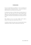
This service manual has instructions and procedures for the Mitsubishi SL-series diesel engines.
The information, specifications and illustrations in this manual are on the basis of the information that was current at
the time this issue was written.
Correct servicing, test and repair procedures will give the engine a long service life. Before starting a test, repair or
rebuild job, the serviceman must read the respective sections of this manual to know all the component he will work
on.
Continuing improvement of product design may have caused changes to your engine which are not included in this
manual.
Whenever a question arises regarding your engine, or this manual, consult your Mitsubishi dealer for the latest
available information.
Service Manual
Mitsubishi SL-Series diesel engines
Version 08/2004
Copyright © 2004 MHI Equipment Europe B.V.
Service Manual Mitsubishi SL-Series diesel engines
Version 08/2004
ENGLISH
1 / 195
HOW TO USE THIS MANUAL
Exploded views
In the exploded views, the component parts are separated but so arranged to show their relationship to the whole.
Index numbering is used to identify the parts and to indicate a sequence in which the parts are to be removed for
disassembly, or they are to be installed for assembly.
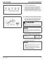
Symbols
The following symbols are used in this manual to emphasize important and critical instructions:
Indicates a condition that is essential to highlight.
NOTE
Indicates a condition that can cause engine damage
CAUTION
WARNING
Indicates a condition that can cause personal injury or
death.
Definition of locational terms
The fan end is “front” and the flywheel end is “rear”. The words “left” and “right” are as these directions would appear
as seen from the flywheel side. The cylinder sequencing begins on the front side (timing gearcase side) of the
engine and works its way to the flywheel side.
Dimensional or specification terms
Nominal size
Is the named size which has no specified limits of accuracy.
Standard
Is the dimension of a part to be attained at the time of
assembly, or the standard performance.
Limit
Is the maximum or minimum permissible limit beyond which a
part must be repaired or replaced.
Tightening torques
Tighten bolts, nuts, etc. in a wet condition (apply oil to threads) when specified as [WET]. Tighten them in a dry
condition unless so specified. Use the general tightening torques unless otherwise specified.
2 / 195
ENGLISH
Service Manual Mitsubishi SL-Series diesel engines
Version 08/2004
TABLE OF CONTENTS
TABLE OF CONTENTS
GENERAL INFORMATION
1
2
3
MODEL IDENTIFICATION AND SERIAL NUMBER LOCATION.................................................... 10
1.1 Model identification location................................................................................................... 10
1.2 Serial Number Location ......................................................................................................... 11
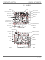
COMPONENT LOCATION.............................................................................................................. 12
2.1 S3L/S3L2 ............................................................................................................................... 12
2.2 Engine S3L-T/S3L2-T ............................................................................................................ 13
2.3 S4L/S4L2 ............................................................................................................................... 14
2.4 Engine S4L-T/S4L2-T ............................................................................................................ 15
SPECIFICATIONS .......................................................................................................................... 16
OVERHAUL INSTRUCTIONS
4
5
6
7
DETERMINING WHEN TO OVERHAUL THE ENGINE ................................................................. 18
COMPRESSION PRESSURE MEASUREMENT............................................................................ 19
5.1 Inspection............................................................................................................................... 19
5.2 Measurement ......................................................................................................................... 19
TROUBLESHOOTING .................................................................................................................... 20
6.1 General .................................................................................................................................. 20
6.2 Engine troubleshooting .......................................................................................................... 21
6.3 Starting system troubleshooting............................................................................................. 27
BASIC PRECAUTIONS FOR DISASSEMBLY AND ASSEMBLY................................................... 29
7.1 Disassembly........................................................................................................................... 29
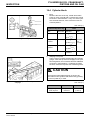
7.2 Assembly ............................................................................................................................... 29
DISASSEMBLY
8
9
10
11
12
13
14
15
PREPARATION FOR DISASSEMBLY............................................................................................ 32
8.1 Engine oil draining ................................................................................................................. 32
8.2 Coolant draining 1 .................................................................................................................. 32
ELECTRICAL SYSTEM .................................................................................................................. 33
9.1 Starter .................................................................................................................................... 33
9.2 Alternator ............................................................................................................................... 35
Cooling System ............................................................................................................................... 38
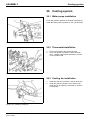
10.1 Cooling fan removal ............................................................................................................... 38
10.2 Thermostat case removal ...................................................................................................... 38
10.3 Water pump assembly removal ............................................................................................. 38
Fuel System .................................................................................................................................... 39
11.1 Fuel injection pipe removal .................................................................................................... 39
11.2 Fuel injection nozzle removal................................................................................................. 39
11.3 Governor assembly removal .................................................................................................. 39
11.4 Governor weight removal....................................................................................................... 40
11.5 Fuel injection pump removal .................................................................................................. 40
Lubrication System.......................................................................................................................... 41
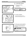
12.1 Oil filter removal ..................................................................................................................... 41
12.2 Pressure relief valve removal................................................................................................. 41
12.3 Oil pressure switch removal................................................................................................... 41
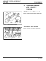
AIR INLET SYSTEM AND EXHAUST SYSTEM ............................................................................. 42
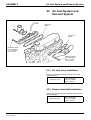
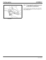
13.1 Exhaust manifold removal...................................................................................................... 42
13.2 Air inlet cover removal ........................................................................................................... 42
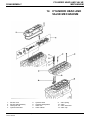
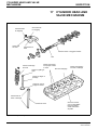
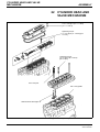
CYLINDER HEAD AND VALVE MECHANISM ............................................................................... 43
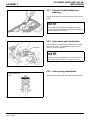
14.1 Rocker shaft assembly removal............................................................................................. 44
14.2 Rocker shaft disassembly ...................................................................................................... 44
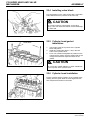
14.3 Cylinder head bolt removal .................................................................................................... 44
14.4 Cylinder head assembly removal........................................................................................... 45
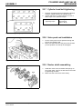
14.5 Valve and valve spring removal ............................................................................................. 45
14.6 Valve stem seal removal........................................................................................................ 45
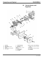
Timing Gears and Flywheel............................................................................................................. 46
Service Manual Mitsubishi SL-Series diesel engines
Version 08/2004
ENGLISH
3 / 195
TABLE OF CONTENTS
16
15.1 Flywheel removal ................................................................................................................... 47
15.2 Rear plate removal................................................................................................................. 47
15.3 Oil seal case removal............................................................................................................. 48
15.4 Tappet removal ...................................................................................................................... 48
15.5 Speedometer driven gear removal......................................................................................... 48
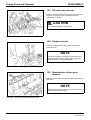
15.6 Crankshaft pulley removal ..................................................................................................... 49
15.7 Timing gear case removal...................................................................................................... 49
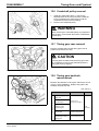
15.8 Timing gear backlash measurement...................................................................................... 49
15.9 Idler gear removal .................................................................................................................. 50
15.10Camshaft removal.................................................................................................................. 50
15.11Fuel injection pump camshaft removal .................................................................................. 50
15.12Gear removal (when required) ............................................................................................... 51
15.13Oil pump removal................................................................................................................... 51
15.14Front plate removal ................................................................................................................ 51
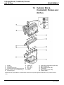
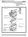
Cylinder Block, Crankshaft, Pistons and Oil Pan ............................................................................ 52
16.1 Oil pan removal...................................................................................................................... 53
16.2 Oil screen removal ................................................................................................................. 53
16.3 Thrust clearance measurement for connecting rod big end................................................... 53
16.4 Connecting rod cap removal .................................................................................................. 54
16.5 Piston removal ....................................................................................................................... 54
16.6 End play measurement for crankshaft ................................................................................... 54
16.7 Main bearing cap removal...................................................................................................... 55
16.8 Crankshaft removal................................................................................................................ 55
16.9 Piston separation from connecting rod .................................................................................. 55
INSPECTION
17
18
19
CYLINDER HEAD AND VALVE MECHANISM ............................................................................... 58
17.1 Cylinder head......................................................................................................................... 59
17.2 Rocker arms and rocker shaft................................................................................................ 59
17.3 Valve springs ......................................................................................................................... 60
17.4 Valve push rods ..................................................................................................................... 60
17.5 Valves, valve guides and valve seats .................................................................................... 60
17.6 Combustion jet replacement .................................................................................................. 64
TIMING GEARS AND FLYWHEEL ................................................................................................. 66
18.1 Camshaft................................................................................................................................ 67
18.2 Fuel injection pump camshaft ................................................................................................ 68
18.3 Tappets .................................................................................................................................. 69
18.4 Idler gear................................................................................................................................ 69
18.5 Flywheel and ring gear........................................................................................................... 70
CYLINDER BLOCK, CRANKSHAFT, PISTONS AND OIL PAN ..................................................... 71
19.1 Pistons, Piston Rings and Piston Pins ................................................................................... 72
19.2 Connecting rods..................................................................................................................... 74
19.3 Crankshaft.............................................................................................................................. 75
19.4 Cylinder block ........................................................................................................................ 79
ASSEMBLY
20
21
Cylinder Block, Crankshaft, Pistons and Oil pan............................................................................. 82
20.1 Main bearing installation ........................................................................................................ 83
20.2 Crankshaft installation............................................................................................................ 83
20.3 Main bearing cap installation ................................................................................................. 83
20.4 Side seal installation .............................................................................................................. 85
20.5 Piston assembling to connecting rod ..................................................................................... 85
20.6 Piston ring installation ............................................................................................................ 87
20.7 Piston and connecting rod installation ................................................................................... 87
20.8 Connecting rod cap installation.............................................................................................. 88
20.9 Oil screen installation............................................................................................................. 89
20.10Oil pan installation.................................................................................................................. 89
Timing Gears and Flywheel............................................................................................................. 91
21.1 Front plate installation............................................................................................................ 92
4 / 195
ENGLISH
Service Manual Mitsubishi SL-Series diesel engines
Version 08/2004
TABLE OF CONTENTS
22
23
24
25
26
27
21.2 Oil pump installation............................................................................................................... 92
21.3 Engine turning........................................................................................................................ 92
21.4 Engine turning........................................................................................................................ 93
21.5 Camshaft installation.............................................................................................................. 93
21.6 Idler gear installation.............................................................................................................. 94
21.7 Timing gear case installation ................................................................................................. 94
21.8 Crankshaft pulley nut tightening............................................................................................. 94
21.9 P.T.O. gear installation .......................................................................................................... 95
21.10Speedometer driven gear installation .................................................................................... 95
21.11Tappet installation.................................................................................................................. 95
21.12Oil seal case installation ........................................................................................................ 96
21.13Rear plate installation ............................................................................................................ 96
21.14Flywheel installation............................................................................................................... 96
CYLINDER HEAD AND VALVE MECHANISM ............................................................................... 98
22.1 Cylinder head bottom face cleaning....................................................................................... 99
22.2 Valve stem seal installation.................................................................................................... 99
22.3 Valve spring installation ......................................................................................................... 99
22.4 Installing valve block ............................................................................................................ 100
22.5 Cylinder head gasket installation ......................................................................................... 100
22.6 Cylinder head installation..................................................................................................... 100
22.7 Cylinder head bolt tightening ............................................................................................... 101
22.8 Valve push rod installation ................................................................................................... 101
22.9 Rocker shaft assembling...................................................................................................... 101
22.10Rocker shaft assembly installation....................................................................................... 102
22.11Valve clearance adjustment................................................................................................. 102
22.12Rocker cover installation...................................................................................................... 102
Air Inlet System and Exhaust System ........................................................................................... 103
23.1 Air inlet cover installation ..................................................................................................... 103
23.2 Exhaust manifold installation ............................................................................................... 103
Fuel System .................................................................................................................................. 104
24.1 Fuel injection nozzle installation .......................................................................................... 104
24.2 Fuel injection pump installation............................................................................................ 104
24.3 Flyweight assembly installation............................................................................................ 104
24.4 Sliding sleeve installation..................................................................................................... 105
24.5 Governor assembly installation............................................................................................ 105
24.6 Fuel injection line installation ............................................................................................... 105
Lubrication system ........................................................................................................................ 106
25.1 Pressure relief valve installation .......................................................................................... 106
25.2 Oil filter installation............................................................................................................... 106
25.3 Oil pressure switch installation............................................................................................. 106
Cooling system.............................................................................................................................. 107
26.1 Water pump installation ....................................................................................................... 107
26.2 Thermostat installation......................................................................................................... 107
26.3 Cooling fan installation......................................................................................................... 107
26.4 Thermoswitch and thermounit combination installation ....................................................... 108
Electrical System........................................................................................................................... 109
27.1 Glow plug installation ........................................................................................................... 109
27.2 Alternator installation ........................................................................................................... 109
ELECTRICAL SYSTEM
28
29
30
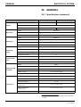
GENERAL ..................................................................................................................................... 112
28.1 Specifications (standard) ..................................................................................................... 112
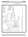
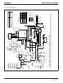
28.2 Wiring diagrams ................................................................................................................... 113
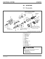
STARTER...................................................................................................................................... 115
29.1 Disassembly......................................................................................................................... 115
29.2 Inspection............................................................................................................................. 116
29.3 Assembly ............................................................................................................................. 119
29.4 Inspection and Testing after Assembly ................................................................................ 120
ALTERNATOR .............................................................................................................................. 122
Service Manual Mitsubishi SL-Series diesel engines
Version 08/2004
ENGLISH
5 / 195
TABLE OF CONTENTS
31
32
33
30.1 Disassembly......................................................................................................................... 122
30.2 Inspection............................................................................................................................. 124
30.3 Assembly ............................................................................................................................. 127
KEY SHUTOFF SYSTEM (ETS solenoid type)............................................................................. 128
31.1 General ................................................................................................................................ 128
31.2 Cord color (standard) ........................................................................................................... 128
31.3 Shutoff solenoid installation ................................................................................................. 128
31.4 Inspection after assembly .................................................................................................... 129
KEY SHUTOFF SYSTEM (ETR solenoid type)............................................................................. 130
32.1 General ................................................................................................................................ 130
32.2 Cord color (standard) ........................................................................................................... 130
32.3 Shutoff solenoid installation ................................................................................................. 131
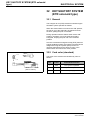
AUTOMATIC GLOW SYSTEM .................................................................................................... 132
33.1 General ................................................................................................................................ 132
33.2 Glow timer specification (standard)...................................................................................... 132
33.3 Glow plug relay specifications (standard) ............................................................................ 133
33.4 Glow plug inspection............................................................................................................ 133
COOLING SYSTEM
34
35
GENERAL ..................................................................................................................................... 136
34.1 Schematic ............................................................................................................................ 136
34.2 Specifications (standard) ..................................................................................................... 136
INSPECTION ................................................................................................................................ 137
35.1 Water pump ......................................................................................................................... 138
35.2 Thermostat (standard) ......................................................................................................... 138
35.3 Thermoswitch (standard) ..................................................................................................... 139
35.4 Thermounit (standard) ......................................................................................................... 139
LUBRICATION SYSTEM
36
37
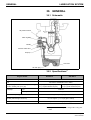
GENERAL ..................................................................................................................................... 142
36.1 Schematic ............................................................................................................................ 142
36.2 Specifications....................................................................................................................... 142
INSPECTION ................................................................................................................................ 143
37.1 Oil pump............................................................................................................................... 143
37.2 Oil pressure switch............................................................................................................... 143
37.3 Pressure relief valve ............................................................................................................ 144
FUEL SYSTEM
38
39
40
41
42
43
GENERAL ..................................................................................................................................... 146
38.1 Schematic ............................................................................................................................ 146
38.2 Specifications (standard) ..................................................................................................... 147
FUEL INJECTION NOZZLE .......................................................................................................... 148
39.1 Inspection............................................................................................................................. 148
39.2 Disassembly and assembly ................................................................................................. 150
FUEL INJECTION PUMP.............................................................................................................. 151
40.1 Test on engine ..................................................................................................................... 151
40.2 Disassembly......................................................................................................................... 151
40.3 Inspection............................................................................................................................. 155
40.4 Assembly ............................................................................................................................. 156
GOVERNOR ................................................................................................................................. 159
41.1 Disassembly and inspection ................................................................................................ 159
41.2 Assembly ............................................................................................................................. 160
41.3 Torque spring set installation ............................................................................................... 161
FUEL PUMP.................................................................................................................................. 162
42.1 Inspection............................................................................................................................. 162
FUEL FILTER................................................................................................................................ 163
AIR INLET SYSTEM AND EXHAUST SYSTEM
44
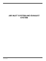
GENERAL ..................................................................................................................................... 166
6 / 195
ENGLISH
Service Manual Mitsubishi SL-Series diesel engines
Version 08/2004
TABLE OF CONTENTS
45
44.1 Schematic ............................................................................................................................ 166
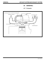
INSPECTION ................................................................................................................................ 167
45.1 Inspection procedure ........................................................................................................... 167
MAINTENANCE
46
47
48
49
50
51
52
53
54
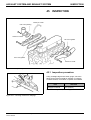
LUBRICATION AND MAINTENANCE CHART ............................................................................. 170
ENGINE OIL AND OIL FILTER ..................................................................................................... 172
47.1 Engine oil specifications....................................................................................................... 172
47.2 Oil level check...................................................................................................................... 172
47.3 Oil and oil filter change ........................................................................................................ 173
47.4 Oil filter change .................................................................................................................... 173
VALVE CLEARANCE.................................................................................................................... 175
FUEL INJECTION TIMING............................................................................................................ 177
49.1 Preparation .......................................................................................................................... 177
49.2 Adjustment ........................................................................................................................... 179
FUEL FILTER................................................................................................................................ 180
50.1 Fuel filter with [AIR] valve .................................................................................................... 180
50.2 Cartridge (air vent screw) type fuel filter .............................................................................. 180
FUEL SYSTEM PRIMING ............................................................................................................. 181
51.1 Engine with fuel filter with [AIR] valve .................................................................................. 181
51.2 Engine with cartridge (air vent screw) type fuel filter ........................................................... 181
IDLE RPM SETTING..................................................................................................................... 182
FUEL INJECTION NOZZLES........................................................................................................ 183
53.1 Injection pressure (valve opening pressure) test ................................................................. 183
53.2 Orifice restriction test ........................................................................................................... 183
53.3 Nozzle tip washing and replacement ................................................................................... 183
53.4 Installation............................................................................................................................ 183
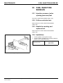
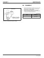
FAN BELT ..................................................................................................................................... 184
SERVICE DATA
55
56
57
58
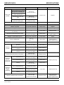
SPECIFICATIONS ........................................................................................................................ 186
55.1 Basic engine components.................................................................................................... 186
55.2 Lubrication system ............................................................................................................... 188
55.3 Fuel system.......................................................................................................................... 188
55.4 Air inlet system and exhaust system.................................................................................... 188
55.5 Cooling system (standard) ................................................................................................... 189
55.6 Electrical system .................................................................................................................. 189
TIGHTENING TORQUES ............................................................................................................. 191
56.1 Major bolts and nuts............................................................................................................. 191
56.2 Torques for bolts and nuts with standard threads................................................................ 192
56.3 Torques for plugs with taperlock threads ............................................................................. 192
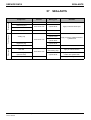
SEALANTS.................................................................................................................................... 193
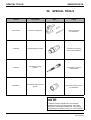
SPECIAL TOOLS .......................................................................................................................... 194
Service Manual Mitsubishi SL-Series diesel engines
Version 08/2004
ENGLISH
7 / 195
TABLE OF CONTENTS
8 / 195
ENGLISH
Service Manual Mitsubishi SL-Series diesel engines
Version 08/2004
GENERAL INFORMATION
Service Manual Mitsubishi SL-Series diesel engines
Version 08/2004
ENGLISH
9 / 195
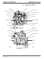
MODEL IDENTIFICATION AND SERIAL
NUMBER LOCATION
General
General
t
1
MODEL
IDENTIFICATION AND
SERIAL NUMBER
LOCATION
1.1
Model identification location
•
The model identification is embossed on the right
side of the cylinder block, near the fuel injection
pump mount.
The model identifications and displacements of the
engines in current production are as listed below:
•
Displacement
Figure 1
Model identification location
S3L
1.125 liters (68.7 cu in.)
S3L2
1.318 liters (80.4 cu in.)
S4L
1.500 liters (91.5 cu in.)
S4L2
1.758 liters (107.3 cu in.)
•
A scheme of coding used for identifying the
engines in current production is as follows:
S 4 L (2) – 61 A
S - Identification of “Sagamihara Machinery Works”
4 - Number-of-cylinders code [“4” stands for four
cylinders]
L - Series code [Bore: 78 mm (3.07 in.)]
(2) - Stroke code
•
(No code: 78.5 mm (3.09 in.)
•
2: 92 mm (3.62 in.)
61 - Export code
A - Specification code
10 / 195
ENGLISH
Service Manual Mitsubishi SL-Series diesel engines
Version 08/2004
MODEL IDENTIFICATION AND SERIAL
NUMBER LOCATION
General
1.2
t
Serial Number Location
The serial number is punched on the cylinder block,
near the fuel injection pump mount.
Serial number
Figure 2
Serial number location
Service Manual Mitsubishi SL-Series diesel engines
Version 08/2004
ENGLISH
11 / 195
COMPONENT LOCATION
GENERAL INFORMATION
GENERAL INFORMATION
2
COMPONENT
LOCATION
2.1
S3L/S3L2
Hanger
Oil filler
Air vent screw
Fuel injection nozzle
Fuel injection pump
Air inlet cover
Water pump
Stop solenoid
Oil filler
Fuel filter
Coolant drain plug
Oil pressure switch
Dipstick
Crankshaft pulley
Oil filter
Oil drain plug
FRONT
REAR
Thermoswitch
RIGHT SIDE VIEW
Exhaust manifold
Thermostat
Hanger
Flywheel housing
Alternator
Starter
Fan
Flywheel
V-belt
Oil pan
FRONT
REAR
LEFT SIDE VIEW
12 / 195
ENGLISH
Service Manual Mitsubishi SL-Series diesel engines
Version 08/2004
GENERAL INFORMATION
COMPONENT LOCATION
2.2
Hanger
Engine S3L-T/S3L2-T
Oil filler
Air vent screw
Fuel injection nozzle
Fuel injection pump
Air inlet cover
Water pump
Stop solenoid
Oil filler
Fuel filter
Coolant drain plug
Oil pressure switch
Dipstick
Crankshaft pulley
Oil filter
Oil drain plug
REAR
Thermoswitch
FRONT
RIGHT SIDE VIEW
Turbocharger
Exhaust manifold
Thermostat
Hanger
Flywheel housing
Alternator
Starter
Fan
V-belt
Flywheel
Oil pan
FRONT
REAR
LEFT SIDE VIEW
Service Manual Mitsubishi SL-Series diesel engines
Version 08/2004
ENGLISH
13 / 195
COMPONENT LOCATION
GENERAL INFORMATION
2.3
Hanger
S4L/S4L2
Oil filler
Air vent screw
Fuel injection nozzle
Fuel injection pump
Air inlet cover
Water pump
Stop solenoid
Oil filler
Fuel filter
Coolant drain plug
Oil pressure switch
Oil filter
Crankshaft pulley
Oil drain plug
Dipstick
REAR
RIGHT SIDE VIEW
FRONT
Thermoswitch
Exhaust manifold
Thermostat
Hanger
Flywheel housing
Alternator
Starter
Fan
Flywheel
V-belt
Oil pan
FRONT
14 / 195
LEFT SIDE VIEW
ENGLISH
REAR
Service Manual Mitsubishi SL-Series diesel engines
Version 08/2004
GENERAL INFORMATION
COMPONENT LOCATION
2.4
Hanger
Engine S4L-T/S4L2-T
Oil filler
Air vent screw
Fuel injection nozzle
Fuel injection pump
Air inlet cover
Water pump
Stop solenoid
Oil filler
Fuel filter
Oil pressure switch
Oil filter
Crankshaft pulley
Oil drain plug
REAR
Dipstick
RIGHT SIDE VIEW
Thermoswitch
FRONT
Turbocharger
Exhaust manifold
Thermostat
Hanger
Flywheel housing
Alternator
Starter
Fan
Flywheel
V-belt
Oil pan
FRONT
Service Manual Mitsubishi SL-Series diesel engines
Version 08/2004
LEFT SIDE VIEW
ENGLISH
REAR
15 / 195
SPECIFICATIONS
GENERAL INFORMATION
GENERAL INFORMATION
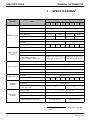
SPECIFICATIONS1
3
System
Model
Item
S3L
Type
S3L-T
S3L2
3
Bore x Stroke (mm)
Total displacement (l)
78x92
78x78.5
78x92
1.125
1.318
1.500
1.758
22
1-3-2
135
139
1-3-4-2
135
Lubricating method
139
Oil filter
Shallow type oil pan: 3.7/2.3
Deep type oil pan: 5.7/3.1
Fuel injection pressure
140 kgf/cm2
Diesel fuel; see chapter 7
Centrifugal weight type
Air cleaner
Paper-element type
Without TD025 Without TD025 Without TD025 Without
Cooling method
TD03
Forced circulation of water
Water pump
Centrifugal type
Coolant capacity (l)
(Engine proper only)
1.8
Starter (V - kW)
2.5
12 - 1.6 or 12 - 1.7 or 12 - 2.0
Alternator (V - A)
AC generator (12 - 50)
Glow plug
Sheathed type
Battery
(capacity depends on application)
Table 1
Shallow type oil pan: 5.5/3.7
Deep type oil pan: 7.6/4.2
Throttle type
Governor
ELECTRICAL
SYSTEM
159
Bosch M
Fuel to be used
COOLING
SYSTEM
155
Paper element type
Nozzle
Turbocharger model
159
Trochoid pump
Fuel injection pump
INTAKE SYSTEM
155
Forced lubrication
Oil pump
FUEL SYSTEM
S4L2-T
78x78.5
Firing order
Oil capacity:
FULL level/EMPTY level (l)
(Exclusive of oil filter capacity 0.5 l)
S4L2
4
Compression ratio
LUBRICATING
SYSTEM
S4L-T
Swirl chamber type
No. of cylinders
Dry weight (kg)
S4L
4-cycle, water-cooled, vertical, overhead valve, diesel engine
Combustion chamber
ENGINE PROPER
S3L2-T
12V, 65 Ah or more
12V, 80 Ah or more
Specifications
1. All specifications are subject to change without any prior
notice.
16 / 195
ENGLISH
Service Manual Mitsubishi SL-Series diesel engines
Version 08/2004
OVERHAUL INSTRUCTIONS
Service Manual Mitsubishi SL-Series diesel engines
Version 08/2004
ENGLISH
17 / 195
DETERMINING WHEN TO
OVERHAUL THE ENGINE
OVERHAUL INSTRUCTIONS
OVERHAUL INSTRUCTIONS
4
DETERMINING WHEN
TO OVERHAUL THE
ENGINE
Generally, when to overhaul the engine is to be
determined by taking into account a drop in
compression pressure as well as an increase in lube oil
consumption and excessive blowby gases.
Lower power or loss of power, an increase in fuel
consumption, a drop in lube oil pressure, hard starting
and excessive abnormal noise are also troubles.
These troubles, however, are not always the result of
low compression pressure and give no valid reason for
overhauling the engine.
The engine develops troubles of widely different
varieties when the compression pressure drops in it.
Following are the typical troubles caused by the
compression pressure failure:
1.
2.
3.
4.
5.
6.
7.
Low power or loss of power
Increase in fuel consumption
Increase in lube oil consumption
Excessive blowby through breather due to worn
cylinders, pistons, etc.
Excessive blowby due to poor seating of worn inlet
and exhaust valves
Hard starting or failure to start
Excessive engine noise
In most cases, these troubles occur concurrently.
Some of them are directly caused by low compression
pressure, but others are not. Among the troubles listed
above, (2) and (6) are caused by a fuel injection pump
improperly adjusted with respect to injection quantity or
injection timing, worn injection pump plungers, faulty
injection nozzles, or poor care of the battery, starter
and alternator.
The trouble to be taken into account as the most valid
reason for overhauling the engine is (4): in actually
determining when to overhaul the engine, it is
reasonable to take this trouble into account in
conjunction with the other ones.
18 / 195
ENGLISH
Service Manual Mitsubishi SL-Series diesel engines
Version 08/2004
COMPRESSION PRESSURE
MEASUREMENT
OVERHAUL INSTRUCTIONS
OVERHAUL INSTRUCTIONS
t
5
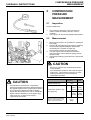
COMPRESSION
PRESSURE
MEASUREMENT
5.1
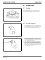
Inspection
Check to make sure:
1.
Figure 3
Compression gauge and adaptor
2.
5.2
t
1.
2.
3.
4.
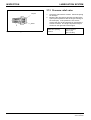
Figure 4
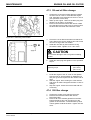
•
CAUTION
•
Move the control lever to a position for shutting off
fuel supply.
Remove all glow plugs from the engine. Install the
compression gauge and adaptor (ST332270)
combination to a cylinder on which the
compression pressure is to be measured.
Turn the engine with the starter and read the
gauge pressure at the instant the gauge pointer
comes to stop.
If the gauge reading is below the limit, overhaul the
engine.
Be sure to measure the compression pressure
on all cylinders.
The compression pressure varies with change of
engine rpm. This makes it necessary to check
engine rpm at the time of measuring the
compression pressure.
Standard
Engine speed, rpm
It is important to measure the compression
pressure at regular intervals to obtain the data on
the gradual change of the compression pressure.
The compression pressure would be slightly
higher than the standard in a new or overhauled
engine owing to breaking-in of the piston rings,
valve seats, etc. It drops as the engine
components wear down.
Service Manual Mitsubishi SL-Series diesel engines
Version 08/2004
Measurement
CAUTION
Measuring compression pressure
•
•
The crankcase oil level is correct, and the air
cleaner, starter and battery are all in normal
condition.
The engine is at the normal operating temperature.
Compression pressure, kgf/
cm2 (psi) [kPa]
Maximum permissible difference
between average compression
pressure of all cylinders in one
engine, kgf/cm2 (psi) [kPa]
ENGLISH
290
Limit
--
SL
30
(427)
[2 942]
23
(327)
[2 256]
SL2
32
(455)
[3 138]
25
(356)
[2 452]
3
(42.7)
[294]
--
19 / 195
TROUBLESHOOTING
OVERHAUL INSTRUCTIONS
OVERHAUL INSTRUCTIONS
6
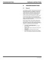
TROUBLESHOOTING
6.1
General
The diagnosis of troubles, especially those caused by a
faulty fuel injection pump or injection nozzles, or low
compression pressure, can be difficult. It requires a
careful inspection to determine not which item is the
cause, but how may causes are contributing to the
trouble, someone of which is the primary cause.
Several causes may be contributing to a single trouble.
On the following pages, there are troubleshooting
charts on which engine troubles can be traced to their
causes. Each chart has items to be verified ahead and
suggested inspection procedure.
Diesel engines exhibit some marked characteristics
during operation. Knowing these characteristics will
help minimize time lost in tracing engine troubles to
their source. Following are the characteristics of diesel
engines you should know about for diagnosis:
•
•
•
•
•
20 / 195
ENGLISH
Combustion knock (diesel knock)
Some black exhaust smoke (when the engine
picks up load)
Vibration (due to high compression pressure and
high torque)
Hunting (when the engine speed is quickly
decreased)
Some white exhaust smoke (when the engine is
cold, or shortly after the engine has been started)
Service Manual Mitsubishi SL-Series diesel engines
Version 08/2004
OVERHAUL INSTRUCTIONS
TROUBLESHOOTING
6.2
Engine troubleshooting
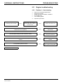
6.2.1 Problem 1: Hard starting
Is heating system normal?
No Z
1.
•
•
•
•
Items to be checked ahead of time
Clogged air cleaner
Wrong oil grade for weather conditions
Poor quality fuel
Low cranking speed
2.
Inspection procedure
Glow plugs are energized
shortly after starter switch is
turned to ON.
No Z
Check control timer unit.
No Z
Check fuel filter, fuel lines
and fuel tank.
No Z
Make adjustment to the
timing and clearance.
No Z
Make adjustment to the
nozzles.
No Z
Check valves, piston rings
and cylinder head gasket.
VYes
Are fuel lines free of restriction? (Is fuel pump operating properly when
starter switch in ON position?)
V Yes
Are fuel injection timing and valve clearance correct?
V Yes
Is fuel injection nozzle discharge pattern normal? Is injection pressure
correct?
V Yes
Is compression pressure correct?
V Yes
Fuel injection pump is faulty.
Service Manual Mitsubishi SL-Series diesel engines
Version 08/2004
ENGLISH
21 / 195
TROUBLESHOOTING
OVERHAUL INSTRUCTIONS
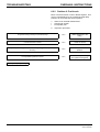
6.2.2 Problem 2: Fuel knock
More or less fuel knock occurs in diesel engines. This
may be caused either by an excessively large delay
period or by a too fast rate of fuel injection.
1.
•
•
Items to be checked ahead of time
Clogged air cleaner
Poor quality fuel
2.
Inspection procedure
Is injection timing correct (not too advanced)?
No Z
Make adjustment to the
timing.
No Z
Check the switch.
No Z
Make adjustment to the
pressure.
No Z
Check valves, piston rings,
and cylinder head gasket.
VYes
Is solenoid switch normal?
V Yes
Is injection pressure (injection nozzle valve opening pressure) correct (not
too low)?
V Yes
Is compression pressure correct?
V Yes
Fuel injection pump is faulty.
22 / 195
ENGLISH
Service Manual Mitsubishi SL-Series diesel engines
Version 08/2004
OVERHAUL INSTRUCTIONS
TROUBLESHOOTING
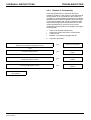
6.2.3 Problem 3: Overheating
Overheating might also be caused by abnormal
operating conditions. If the engine is overheating but its
cooling system is not contributing to this trouble, it is
necessary to check the difference between the ambient
temperature and coolant temperature when the engine
is in normal operation (with the thermostat fully open).
If the ambient temperature is higher than the normal
coolant temperature by more than 60°C (108°C),
investigate other items than those related to the engine
cooling system.
1.
•
•
•
Items to be checked ahead of time
Insufficient coolant and exterior coolant leaks
Loose fan belt
Radiator core openings plugged with dirt
2.
Inspection procedure
Are cooling system components (water pump, water hoses, radiator,
thermostat and cylinder head gasket) normal?
No Z
Check the components.
No Z
Make adjustment to the
timing.
No Z
Check the components and
oil level.
No Z
Make adjustment to the
governor.
VYes
Is injection timing correct?
V Yes
Are lubrication system components (oil filter, oil pump and oil screen)
normal and oil level correct?
V Yes
Is governor adjustment correct?
V Yes
Engine is in continuous fullload operation.
Service Manual Mitsubishi SL-Series diesel engines
Version 08/2004
ENGLISH
23 / 195
TROUBLESHOOTING
OVERHAUL INSTRUCTIONS
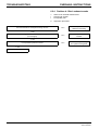
6.2.4 Problem 4: Black exhaust smoke
1.
•
•
Items to be checked ahead of time
Clogged air cleaner
Poor quality fuel
2.
Inspection procedure
Are valve clearance and injection timing correct?
No Z
Make adjustment to the
clearance and timing.
No Z
Make adjustment to the
nozzles.
No Z
Check valves, piston rings
and cylinder head gasket.
VYes
Is injection nozzle discharge pattern normal? Is injection pressure correct
(not too high)?
V Yes
Is compression pressure correct?
V Yes
Fuel injection pump is faulty.
24 / 195
ENGLISH
Service Manual Mitsubishi SL-Series diesel engines
Version 08/2004
OVERHAUL INSTRUCTIONS
TROUBLESHOOTING
6.2.5 Problem 5: Erratic idle speeds
1.
•
•
•
Items to be checked ahead of time
Maladjusted engine control
Wrong oil grade for weather conditions
Poor quality fuel
2.
Inspection procedure
Are valve clearance and injection timing correct?
No Z
Make adjustment to the
clearance and timing.
No Z
Make adjustment to the
nozzles.
No Z
Check valves, piston rings
and cylinder head gasket.
VYes
Is injection nozzle discharge pattern normal? Is injection pressure
constant?
V Yes
Is compression pressure correct (no difference in compression pressure
between cylinders)?
V Yes
Fuel injection pump is faulty.
Service Manual Mitsubishi SL-Series diesel engines
Version 08/2004
ENGLISH
25 / 195
TROUBLESHOOTING
OVERHAUL INSTRUCTIONS
6.2.6 Problem 6: Low power or loss of
power
1.
•
•
•
•
•
•
Items to be checked ahead of time
Stuck running parts
Wrong oil grade for weather conditions
Poor quality fuel
Clogged air cleaner
Restricted exhaust line
Faulty power take-off
2.
Inspection procedure
Are valve clearance and injection timing correct?
No Z
Make adjustment to the
clearance and timing.
No Z
Check fuel tank, fuel filter
and fuel lines.
No Z
Make adjustment to the
governor.
No Z
Make adjustment to the
nozzles.
No Z
Check valves, piston rings
and cylinder head gaskets.
VYes
Are fuel lines free from restriction? (Is fuel pump operating properly when
starter switch is in ON position?)
V Yes
Is governor adjustment correct?
V Yes
Is injection nozzle discharge pattern normal?
Is injection pressure correct?
V Yes
Is compression pressure correct?
V Yes
Fuel injection pump is faulty.
26 / 195
ENGLISH
Service Manual Mitsubishi SL-Series diesel engines
Version 08/2004
OVERHAUL INSTRUCTIONS
TROUBLESHOOTING
6.3
Starting system
troubleshooting
Overruns at low speed → Make reference to “Overrun.”
Faulty starter
motor
Burned contact points in switch
Burned motor coil or switch coil
Layer shorted or grounded field coil
Burned field coil
Layer shorted or grounded armature coil
Burned coil in armature
Mechanical problems
Misaligned armature
Machining fault of parts
Burned motor coil (evidence of rubbing)
Worn bearings
Switch will not turn off only when engine fails to
fire, resulting in damage to motor.
Burned starter
Pinion gap too large.
Hard starting at low
temperatures
Wrong starting system
High resistance in main circuit
Poor quality fuel
Prolonged
cranking
Mechanical problems in engine
Very low ambient temperature
Troubles in engine
No fuel
Burned motor coil
Engine directly coupled to load
Excessive
load
Reverse torque due to incorrect injection timing
Mechanical problems in engine
Starter abused (for moving equipment)
Pinion fails to
shift
No cranking
Pinion shifts
but will not
spin
Pinion butts
ring gear
instead of
meshing
Battery run-down
Loose battery terminals
Defective key switch
Poor S connector contact
S connector missing
Open circuit in engine switch coil
Worn starter brushes
Defective contact points in auxiliary switch
Open circuit in auxiliary switch coil
High resistance in S circuit
Voltage applied to starter too high
Contact points defective in starter switch
Pinion and ring gear improperly chamfered
Battery rating too high
Pinion chamfered insufficiently or wrong
Ring gear chamfered insufficiently or wrong
Ring gear end face badly worn (ring gear not hardened properly)
Pinion will not shift
Pinion metal jammed with dirt
Overrunning clutch jammed with
foreign matter
Shift lever jammed
Solenoid switch plunger jammed
Shift lever broken
Contact points close to early
Shift lever broken
Pinion gap too large
Pinion shifted excessively
Pinion tooth worn round
Ring gear locally chipped
Four or five teeth chipped
Pinion is forced into mesh with ring gear again when starter is
coasting
Overrunning clutch shell peeled
Pinion chamfered insufficiently or wrong
Pinion is chipped
Service Manual Mitsubishi SL-Series diesel engines
Version 08/2004
ENGLISH
27 / 195
TROUBLESHOOTING
Key not returning
completely
Key switch
faulty
OVERHAUL INSTRUCTIONS
Broken return spring
Sticking
Machining fault of parts
Key not finished to close
tolerances
External obstacle
Rust due to moisture
Starter is energized for hours, resulting
in:
•
Burned hold-in coil
•
Burned armature and field coils
•
Burned subswitch (if so equipped)
Defective contact points
Problems in switch
Overrun
Starter faulty
Pull-in and hold-in coils
unbalance in number of
windings
Pull-in or hold-in coil layer
shorted
•
•
Contact points defective
Switch will not turn off only when engine
fails to fire, resulting in burning of motor
coil
Plunger jammed
•
•
•
Burned motor coil
Burned pull-in and hold-in coils
(minor defect)
Plunger fails to return when
voltage is applied to circuit
between M and (–) terminals and
plunger is pushed in with switch off
starter
Burned motor coil
Burned pull-in and hold-in coils
Machining fault of parts
Shift lever faulty
Lever pivot jammed
Dotted lines indicate failure of contact
points to close
Machining fault
Overrunning clutch jammed
Subswitch faulty
Incorrect
wiring
Sliding part jammed
Sliding surface dirty
Machining fault of lead
Sticking pinion metal
Burned contact points
Assembly fault resulting in
failure to return
Burned hold-in coil and motor coil
External load connected to S circuit
Make reference to “Pull-in and hold-in
coil unbalance”
S and B circuits shorted
Make reference to “Key not returning
completely”
[Other possibility is sticking pinion metal in case of overrun trouble.]
28 / 195
ENGLISH
Service Manual Mitsubishi SL-Series diesel engines
Version 08/2004
OVERHAUL INSTRUCTIONS
BASIC PRECAUTIONS FOR DISASSEMBLY
AND ASSEMBLY
OVERHAUL INSTRUCTIONS
7
BASIC PRECAUTIONS
FOR DISASSEMBLY
AND ASSEMBLY
This section outlines basic precautions recommended
by Mitsubishi that should always be observed.
7.1
1.
2.
3.
4.
5.
6.
7.2
1.
2.
3.
4.
5.
Service Manual Mitsubishi SL-Series diesel engines
Version 08/2004
ENGLISH
Disassembly
Always use tools that are in good condition and be
sure you understand how to use them before
performing any job.
Use an overhaul stand or a work bench, if
necessary. Also, use bins to keep engine parts in
order of removal.
Parts must be restored to their respective
components from which they were removed at
disassembly. This means that all parts must be set
aside separately in groups, each marked for its
component, so that the same combination or set
can be reproduced at assembly.
Pay attention to marks on assemblies,
components and parts for their positions or
directions. Put on marks, if necessary, to aid
assembly.
Carefully check each part or component for any
sign of faulty condition during removal or cleaning.
The part will tell you how it acted or what was
abnormal about it more accurately during removal
or cleaning.
When lifting or carrying a part too heavy or too
awkward for one person to handle, get another
person’s help and, if necessary, use a jack or a
hoist.
Assembly
Wash all parts, except for oil seals, O-rings, rubber
sheets, etc., with cleaning solvent and dry them
with pressure air.
Always use tools that are in good condition and be
sure you understand how to use them before
performing any job.
Use only good-quality lubricants. Be sure to apply
a coat of oil, grease or sealant to parts as
specified.
Be sure to use a torque wrench to tighten parts for
which torques are specified.
Any time the engine is assembled, new gaskets
and O-rings must be installed.
29 / 195
BASIC PRECAUTIONS FOR
DISASSEMBLY AND ASSEMBLY
30 / 195
OVERHAUL INSTRUCTIONS
ENGLISH
Service Manual Mitsubishi SL-Series diesel engines
Version 08/2004
DISASSEMBLY
Service Manual Mitsubishi SL-Series diesel engines
Version 08/2004
ENGLISH
31 / 195
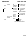
PREPARATION FOR DISASSEMBLY
DISASSEMBLY
DISASSEMBLY
t
8
PREPARATION FOR
DISASSEMBLY
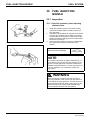
8.1
Engine oil draining1
Remove the drain plug from the bottom of the oil pan
and allow the oil to drain.
Refill capacities
(high level excl. 0.5
liter (0.13 U.S. gal)
of oil in oil filter, liter
(U.S. gal)
S3L/S3L2:
5.7 (1.5) (with deep oil pan)
3.7 (1.0) (with standard oil pan)
S4L/S4L2:
7.7 (2.0) (with deep oil pan)
5.4 (1.4) (with standard oil pan)
Engine oil drain plug
Figure 5
Draining engine oil
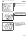
WARNING
Hot oil and components can cause personal injury.
Do not allow hot oil or components to contact skin.
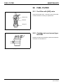
8.2
t
Coolant drain
plug
Coolant draining 1
Loose the drain plug on the right side of the cylinder
block and allow the coolant to drain.
Refill capacities,
liter (U.S. gal)
Figure 6
S3L/S3L2: 1.8 (0.5)
S4L/S4L2: 2.5 (0.7)
Draining coolant
1. Please refer to the applicable engine model specification
sheet for actual data
32 / 195
ENGLISH
Service Manual Mitsubishi SL-Series diesel engines
Version 08/2004
DISASSEMBLY
ELECTRICAL SYSTEM
DISASSEMBLY
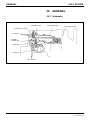
9
ELECTRICAL SYSTEM
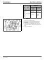
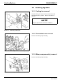
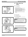
9.1
Starter
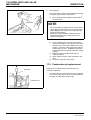
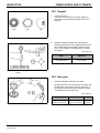
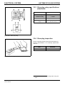
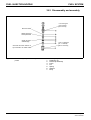
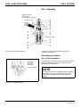
9.1.1 Testing before disassembly
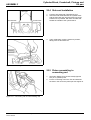
1.
Clearance between pinion and housing (pinion
clearance)
1) Connect the starter to a 12 volt battery as
shown in the illustration to cause the pinion to
shift into cranking position and remain there.
CAUTION
Due to the amount of current being passed through
the solenoid series winding, this test must be made
within 10 seconds.
2)
t
3)
Push in
pinion
0,5 to 2,0 mm
(0.020 to 0.079 in.)
Figure 7
Battery
(12 volts) Starter
Connections for measuring pinion
clearance
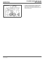
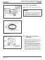
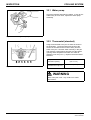
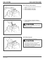
2.
t
Switch
Ammeter
Starter
Tachometer
Battery
(12 volts)
Connections for testing no-load
characteristics
Service Manual Mitsubishi SL-Series diesel engines
Version 08/2004
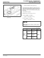
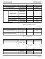
No-load characteristics
1) Connect the starter to a 12 volt battery with an
ammeter capable of indicating several
hundred amperes as shown in the illustration.
2) Close the switch to make sure the pinion shifts
into cranking position properly and the starter
runs at speeds higher than is specified. If the
current draw and/or operating speed is out of
the standard, disassemble the starter for
inspection and repairs.
CAUTION
•
Figure 8
Push the pinion toward the commutator end
by hand to measure its free movement (pinion
clearance).
The pinion clearance must be 0.5 to 2.0 mm
(0.020 to 0.079 in.). If the clearance is out of
this range, make an adjustment to it by adding
or removing the packings on the magnetic
switch. Adding the packings will decrease the
clearance.
•
•
ENGLISH
The size of wires used for this test must be as
large as possible. Tighten the terminals securely.
This starter has a reduction gear. Do not confuse
gear noise with some abnormal noise else.
When measuring the starter speed at the end of
the pinion, be ready for accidental shifting of the
pinion.
33 / 195
ELECTRICAL SYSTEM
DISASSEMBLY
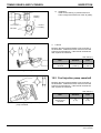
Item
Model
Standard
M8T70471
M1T68281
12 – 2.0
12 – 1.7
11
11.5
Current draw, A
130
maximum
100
maximum
Speed, rpm
3 850
minimum
3 000
minimum
Nominal output, V – kW
No-load
characteristics
Terminal voltage, V
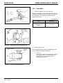
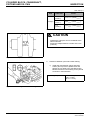
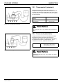
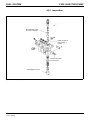
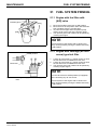
3.
t
Battery
(12 volts)
Connector disconnected
Figure 9
Connections for testing pull-in coil
Magnetic switch
1) Disconnect the connector from the M terminal
of the magnetic switch.
2) Connect the magnetic switch to a 12 volt
battery with a switch as shown in the
illustration to test the pull-in coil. Close the
switch to see if the pinion shifts. If the piston
fails to shift, the magnetic switch is faulty.
CAUTION
Due to the amount of current being passed through
the solenoid series winding, this test must be made
within 10 seconds.
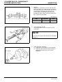
3)
t
Connector disconnected
Battery
(12 volts)
Figure 10
34 / 195
Connect the magnetic switch to a 12 volt
battery with a switch as shown in the
illustration to test the pull-in coil. Close the
switch to see if the pinion shifts. If the piston
fails to shift, the magnetic switch is faulty.
CAUTION
Due to the amount of current being passed through
the solenoid series winding, this test must be made
within 10 seconds.
Connections for testing hold-in coil
ENGLISH
Service Manual Mitsubishi SL-Series diesel engines
Version 08/2004
DISASSEMBLY
ELECTRICAL SYSTEM
4)
t
Connector disconnected
Battery
(12 volts)
Figure 11
Connections for pinion return test
Connect the magnetic switch to a 12 volt
battery with a switch as shown in the
illustration to make a pinion return test. Close
the switch and pull the pinion away from the
commutator end by hand. Release the pinion
to see if it returns immediately when released.
If the pinion fails to so return, the magnetic
switch is faulty.
CAUTION
Due to the amount of current being passed through
the solenoid series winding, this test must be made
within 10 seconds.
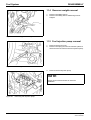
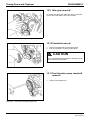
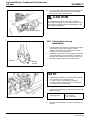
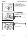
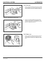
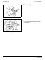
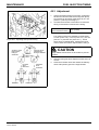
9.1.2 Removal
t
1.
2.
3.
Figure 12
Disconnect the battery wires. Disconnect the
negative (–) wire first.
Disconnect wire (1) from the starter.
Loosen bolts (2) (two) holding starter (3) in position
and remove the starter.
Removing starter
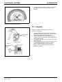
9.2
t
Alternator
9.2.1 Inspection before removal
Alternator on engine
Service Manual Mitsubishi SL-Series diesel engines
Version 08/2004
Alternator charge
too high
Figure 13
Voltage regulator setting too high
Alternator gives
no charge
The correct diagnosis of the charging system requires
a careful inspection with the alternator on the engine to
determine whether or not it is necessary to remove the
alternator from the engine for further inspection. The
following chart, in which two troubles are listed with four
possible causes of each, will help locate the cause of
the trouble:
Alternator drive belt loose
ENGLISH
Ground return circuit defective
Wiring incorrect
Series resistor or winding open-circuited
Voltage regulator setting too low
Alternator output low
Brushes worn
35 / 195
ELECTRICAL SYSTEM
DISASSEMBLY
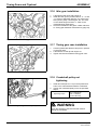
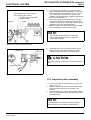
9.2.2 Precautions for removal
t
Following is a list of basic precautions that should
always be observed for removal:
1.
2.
3.
4.
5.
6.
7.
When installing the battery, care must be used to
make sure the negative (–) terminal is grounded.
Do not use a megger (an instrument for high
resistance of electrical materials).
Disconnect the battery cables before charging the
battery.
Do not attempt to disconnect the lead from the B
terminal of the alternator when the engine is
running.
Battery voltage is being applied to the B terminal of
the alternator. Do not ground it.
Do not short or ground the L terminal of the
alternator with a built-in IC regulator.
Do not blow a spray from the steam cleaner nozzle
at the alternator.
9.2.3 Testing voltage setting
t
Ammeter
1.
Switch
2.
Voltmeter
Battery
(12 volts)
3.
4.
Figure 14
Connections for testing voltage setting
Item
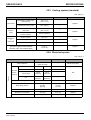
Standard
Voltage setting [at
20°C (68°F)]
14.7 ± 0.3 V
9.2.4 Testing output characteristics
t
Ammeter
1.
2.
Battery
Alternator
indicator light
Switch
3.
4.
5.
6.
Figure 15 Connections for testing output
characteristics (alternator with built-in regulator)
36 / 195
Connect the alternator to a 12 volt battery with an
ammeter, a voltmeter and a switch as shown in the
illustration.
The voltmeter reading must be zero (0) when the
starter switch is in OFF position. It must be lower
than the battery voltage when the switch is in ON
position (the engine will not start).
With one ammeter lead short-circuited, start the
engine.
Read the voltmeter when the ammeter reading is
below five amperes and the engine is running at
1800 min–1 and also at 2500 min–1 with all
electrical loads turned off. The voltage setting
varies with alternator temperature. Generally, the
higher the alternator temperature, the lower the
voltage setting.
ENGLISH
Disconnect the battery ground (negative) cable.
Connect one ammeter lead to the B terminal of the
alternator and the other lead to the positive
terminal of the battery. Connect one voltmeter
lead to the B terminal and the other lead to the
ground.
Connect the battery ground cable.
Start the engine.
Turn on all electrical loads.
Increase the engine speed. Measure the
maximum output current at the specified alternator
speed when the voltmeter reading is 13.5 volts.
Service Manual Mitsubishi SL-Series diesel engines
Version 08/2004
DISASSEMBLY
ELECTRICAL SYSTEM
Standards
Output characteristics
(at normal temperature)
Item
Model
Terminal
voltage/
current
Speed
13.5 V/33 A
2 500 rpm
maximum
13.5 V/47 A
5 000 rpm
maximum
A7T02071C
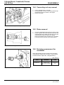
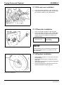
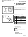
9.2.5 Removal
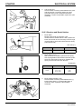
t
1.
2.
3.
4.
5.
Figure 16
Disconnect the battery cables.
Disconnect the lead from the B terminal of the
alternator.
Disconnect the connector from the alternator.
Loosen the brace and support bolts. Move the
alternator toward the engine and remove the drive
belt.
Remove the alternator.
Removing alternator
Service Manual Mitsubishi SL-Series diesel engines
Version 08/2004
ENGLISH
37 / 195
Cooling System
DISASSEMBLY
DISASSEMBLY
10 Cooling System
10.1 Cooling fan removal
t
Hold the fan by one hand and remove the four bolts
that hold the fan in position. Remove the fan and
spacers.
NOTE
Keep the spacers with the fan for installation.
Figure 17
Removing cooling fan
10.2 Thermostat case removal
t
Remove the water pump assembly.
Figure 18
Removing thermostat assembly
10.3 Water pump assembly removal
t
Remove the water pump assembly.
Figure 19
38 / 195
Removing water pump assembly
ENGLISH
Service Manual Mitsubishi SL-Series diesel engines
Version 08/2004
DISASSEMBLY
Fuel System
DISASSEMBLY
11 Fuel System
11.1 Fuel injection pipe removal
t
Disconnect the fuel injection pipes and fuel leak-off
pipe from the fuel injection pump and nozzles.
NOTE
Put plugs or caps on the openings of the injection
pump and nozzle connectors.
Figure 20
Removing fuel injection pipes
11.2 Fuel injection nozzle removal
t
Loosen the fuel injection nozzles with a wrench.
Remove the nozzles and gaskets from the cylinder
head.
NOTE
Remove the gaskets from the cylinder head with a
screwdriver or a similar tool. Discard defective
gaskets.
Figure 21
Removing fuel injection nozzles
11.3 Governor assembly removal
t
1.
2.
3.
Figure 22
Remove the tie rod cover.
Remove the spring from the tie rod with a pliers to
disconnect the tie rod from the fuel injection pump.
Remove the governor assembly.
Removing governor assembly
Service Manual Mitsubishi SL-Series diesel engines
Version 08/2004
ENGLISH
39 / 195
Fuel System
DISASSEMBLY
11.4 Governor weight removal
t
1.
2.
Figure 23
Removing governor weights
11.5 Fuel injection pump removal
t
Figure 24
Remove the sliding sleeve.
Remove the sliding sleeve shaft and governor
weights.
1.
2.
Remove the tie rod cover.
Remove the spring from the tie rod with a pliers to
disconnect the tie rod from the fuel injection pump.
3.
Remove the fuel injection pump.
Removing tie rod
t
NOTE
Keep a record of the thickness of shims for
installation.
Figure 25
40 / 195
Removing fuel injection pump
ENGLISH
Service Manual Mitsubishi SL-Series diesel engines
Version 08/2004
DISASSEMBLY
Lubrication System
DISASSEMBLY
12 Lubrication System
12.1 Oil filter removal
t
1.
2.
Figure 26
Put a container under the oil filter to catch the oil.
Remove the oil filter from the cylinder block with a
filter wrench.
Removing oil filter
12.2 Pressure relief valve removal
t
Remove the pressure relief valve from the cylinder
block.
Figure 27
Removing pressure relief valve
12.3 Oil pressure switch removal
t
Remove the oil pressure switch with Oil Pressure
Switch Socket Wrench (MD998054) (special tool).
Figure 28
Removing oil pressure switch
Service Manual Mitsubishi SL-Series diesel engines
Version 08/2004
ENGLISH
41 / 195
AIR INLET SYSTEM AND EXHAUST
SYSTEM
DISASSEMBLY
DISASSEMBLY
13 AIR INLET SYSTEM
AND EXHAUST
SYSTEM
13.1 Exhaust manifold removal
t
Remove the exhaust manifold from the cylinder head.
Figure 29
Removing exhaust manifold
13.2 Air inlet cover removal
t
Remove the air inlet cover from the cylinder head.
Figure 30
42 / 195
Removing air inlet cover
ENGLISH
Service Manual Mitsubishi SL-Series diesel engines
Version 08/2004
CYLINDER HEAD AND VALVE
MECHANISM
DISASSEMBLY
DISASSEMBLY
14 CYLINDER HEAD AND
VALVE MECHANISM
1.
2.
3.
4.
Rocker cover
Rocker shaft assembly
Valve push rod
Cylinder head bolt
5.
6.
7.
8.
Service Manual Mitsubishi SL-Series diesel engines
Version 08/2004
Cylinder head
Cylinder head gasket
Valve lock
Valve retainer
ENGLISH
9.
10.
11.
12.
Valve spring
Valve
Valve stem seal
Valve cap
43 / 195
CYLINDER HEAD AND VALVE
MECHANISM
DISASSEMBLY
14.1 Rocker shaft assembly
removal
t
1.
2.
Figure 31
Remove the bolts that hold the rocker stays in
position and remove the rocker shaft assembly.
Remove the valve caps.
Removing rocker shaft assemblies
14.2 Rocker shaft disassembly
t
Put identification on each rocker arm as to its location
on the rocker shaft.
Figure 32
Disassembling rocker shaft assembly
14.3 Cylinder head bolt removal
t
Loosen the cylinder head bolts in two or three steps in
the sequence shown.
NOTE
Front
If any parts on the cylinder head are faulty, check the
cylinder head bolts for tightness with a torque wrench
before loosening them.
Figure 33
44 / 195
Cylinder head bolt loosening sequence
ENGLISH
Service Manual Mitsubishi SL-Series diesel engines
Version 08/2004
CYLINDER HEAD AND VALVE
MECHANISM
DISASSEMBLY
14.4 Cylinder head assembly
removal
t
Lift the cylinder head straight up with a hoist.
NOTE
If the gasket is seized and the cylinder head cannot
be separated from the cylinder block, tap around the
thick side portion of the cylinder head with a plastic
hammer.
Figure 34
Removing cylinder head assembly
14.5 Valve and valve spring removal
t
1.
2.
Compress the valve spring with a valve lifter and
remove the valve lock.
Remove the retainer, spring and valve.
NOTE
The valves, retainers, springs and valve locks must
be set aside separately in groups, each tagged for
cylinder number, for correct installation.
Figure 35
Removing valve springs
14.6 Valve stem seal removal
t
Remove the valve stem seals with a pliers.
NOTE
Do not reuse the valve stem seals, but replace them
by new ones.
Figure 36
Removing valve stem seals
Service Manual Mitsubishi SL-Series diesel engines
Version 08/2004
ENGLISH
45 / 195
Timing Gears and Flywheel
DISASSEMBLY
DISASSEMBLY
15 Timing Gears and
Flywheel
1.
2.
3.
4.
5.
6.
Flywheel
Rear plate
Oil seal case; oil seal
Tappet
Speedometer driven gear
P.T.O. gear
46 / 195
7.
8.
9.
Crankshaft pulley
Timing gear case
Idler gear
(Remove 10 thru 12 as an
assembly.)
10. Camshaft gear
11. Thrust plate
12. Camshaft
ENGLISH
(Remove 3 thru 5 as an assembly.)
13. Fuel injection pump camshaft
gear
14. Bearing
15. Fuel injection pump camshaft
16. Oil pump
17. Front plate
Service Manual Mitsubishi SL-Series diesel engines
Version 08/2004
DISASSEMBLY
Timing Gears and Flywheel
15.1 Flywheel removal
t
1.
2.
Have someone hold the crankshaft pulley with a
wrench to prevent the flywheel from rotating.
Remove one of the bolts that hold the flywheel in
position.
WARNING
Always signal each other to prevent possible
personal injury.
Figure 37
Holding flywheel
3.
t
Safety bar
4.
Install a safety bar (M12 x 1.25) into the threaded
hole in the flywheel from which the bolt was
removed in Step (2). Remove the remaining bolts.
Hold the flywheel by hands and withdraw it from
the crankshaft. Joggling the flywheel back and
forth will facilitate removal.
WARNING
When removing the flywheel, wear heavy gloves to
avoid hand injury.
Figure 38
Removing flywheel
15.2 Rear plate removal
t
The rear plate is doweled in position. Pull the plate as
straight as possible when removing it.
Front
Figure 39
Removing rear plate
Service Manual Mitsubishi SL-Series diesel engines
Version 08/2004
ENGLISH
47 / 195
Timing Gears and Flywheel
DISASSEMBLY
15.3 Oil seal case removal
t
Remove the bolts that hold the oil seal case in position.
Remove the case from the cylinder block with a
screwdriver or the like.
CAUTION
Do not cause damage to the oil seal.
Figure 40
Removing oil seal case
15.4 Tappet removal
t
Remove the tappets from the cylinder block with a
valve push rod.
NOTE
The valves, retainers, springs and valve locks must
be set aside separately in groups, each tagged for
cylinder number, for correct installation.
Figure 41
Removing tappets
15.5 Speedometer driven gear
removal
t
Remove the lock plate and speedometer driven gear in
that order.
NOTE
Unless the speedometer driven gear is removed, the
camshaft cannot be removed.
Figure 42
48 / 195
Removing speedometer driven gear
ENGLISH
Service Manual Mitsubishi SL-Series diesel engines
Version 08/2004
DISASSEMBLY
Timing Gears and Flywheel
15.6 Crankshaft pulley removal
t
1.
2.
Install two safety bars (M12 x 1.25) into the
threaded holes in the rear end of the crankshaft.
Put a bar between the safety bars to hold the
crankshaft to prevent it from rotating.
Remove the crankshaft pulley.
WARNING
When removing the crankshaft pulley, be prepared to
stop the job in case the bar slips off the crankshaft to
prevent injury.
Figure 43
Removing crankshaft pulley
15.7 Timing gear case removal
t
Remove the bolts that hold the timing gear case in
position and remove the case.
CAUTION
The front plate is bolted inside the timing gear case.
Do not attempt to remove this plate along with the
timing gear case by tapping.
Figure 44
Front plate attaching bolts
15.8 Timing gear backlash
measurement
t
Measure the backlash of each gear and keep a record
of it for correct installation. Replace the gears if the
backlash exceeds the limit.
Unit: mm (in.)
Item
Standard
Limit
Figure 45
Measuring timing gear backlash
Service Manual Mitsubishi SL-Series diesel engines
Version 08/2004
Timing gear backlash
Crankshaft gear and
idler gear
ENGLISH
Idler gear and
camshaft gear
0.04 to 0.12
(0.001 6 to 0.004 7)
Idler gear and fuel
injection pump
camshaft gear
0.30
(0.011 8)
Camshaft gear and
P.T.O. gear
0.08 to 0.19
(0.003 1 to 0.007 5)
Fuel injection pump
camshaft gear and oil
pump gear
0.07 to 0.20
(0.002 8 to 0.007 9)
49 / 195
Timing Gears and Flywheel
DISASSEMBLY
15.9 Idler gear removal
t
To remove the idler gear, rotate the gear in a direction
of the helix of the teeth to pull it out of mesh.
Figure 46
Removing idler gear
15.10 Camshaft removal
t
1.
2.
Remove the bolts that hold the thrust plate.
Pull the camshaft out of the cylinder block.
CAUTION
Do not cause damage to the lobes or bearing journals
when removing the camshaft.
Figure 47
Removing camshaft
15.11 Fuel injection pump camshaft
removal
t
1.
Figure 48
50 / 195
Remove the stopper bolt.
Removing camshaft stopper bolt
ENGLISH
Service Manual Mitsubishi SL-Series diesel engines
Version 08/2004
DISASSEMBLY
2.
t
Figure 49
Timing Gears and Flywheel
Tap the rear end of the camshaft with a copper bar
to push it out of the front side of the cylinder block.
Removing fuel injection pump camshaft
15.12 Gear removal (when required)
To remove the gears from the camshaft and fuel
injection pump camshaft, use an arbor press.
15.13 Oil pump removal
t
Remove the bolts that hold the oil pump to the cylinder
block and remove the pump.
Figure 50
Removing oil pump
15.14 Front plate removal
t
Remove four bolts that hold the front plate in position.
Tap the plate lightly with a plastic hammer to separate
the gasket.
Figure 51
Removing front plate
Service Manual Mitsubishi SL-Series diesel engines
Version 08/2004
ENGLISH
51 / 195
Cylinder Block, Crankshaft, Pistons
and Oil Pan
DISASSEMBLY
DISASSEMBLY
16 Cylinder Block,
Crankshaft, Pistons and
Oil Pan
1. Oil pan
2. Oil screen
3. Connecting rod cap
4. Connecting rod bearing (lower half)
(Remove 5 thru 10 as an assembly.)
5. Connecting rod
6.
7.
8.
9.
10.
Piston pin
No. 1 ring
No. 2 ring
Oil ring
Piston
11.
12.
13.
14.
15.
16.
Connecting rod bearing (upper half)
Main bearing cap
Main bearing (lower half)
Crankshaft
Main bearing (upper half)
Cylinder block
NOTE: When the cylinder block is to be discarded, remove the components (pressure relief valve, etc.) from the block for
reuse.
52 / 195
ENGLISH
Service Manual Mitsubishi SL-Series diesel engines
Version 08/2004
Cylinder Block, Crankshaft, Pistons
and Oil Pan
DISASSEMBLY
16.1 Oil pan removal
t
1.
2.
Turn the engine upside down.
Tap the bottom corners of the oil pan with a plastic
hammer to remove the oil pan.
CAUTION
Do not attempt to pry off the oil pan by inserting a
screwdriver or a chisel between the oil pan and
cylinder block. Damage to the oil pan can be the
result.
Figure 52
Removing oil pan
16.2 Oil screen removal
t
Loosen the nut that holds the oil screen in position and
remove the screen.
Figure 53
Removing oil screen
16.3 Thrust clearance measurement
for connecting rod big end
t
Install the connecting rod to its crankpin and tighten the
cap nuts to the specified torque. Measure the thrust
clearance with a feeler gauge. If the clearance
exceeds the limit, replace the connecting rod.
Unit: mm (in.)
Figure 54
Item
Standard
Thrust clearance for
connecting rod big
end
0.10 to 0.35
(0.003 9 to 0.013 8)
Limit
0.50
(0.019 7)
Measuring thrust clearance for connecting
rod big end
Service Manual Mitsubishi SL-Series diesel engines
Version 08/2004
ENGLISH
53 / 195
Cylinder Block, Crankshaft, Pistons
and Oil Pan
DISASSEMBLY
16.4 Connecting rod cap removal
t
1.
2.
3.
Figure 55
Removing connecting rod caps
16.5 Piston removal
t
1.
2.
Figure 56
Lay the cylinder block on its side.
Put identification on each connecting rod and cap
combination as to its location in the engine.
Remove the caps.
Turn the crankshaft until the piston is at top center.
Push the piston and connecting rod away from the
crankshaft with the handle of a hammer or the like
until the piston rings are above the cylinder.
Remove the piston and connecting rod. Do Steps
(1) and (2) for the removal of the other pistons.
Removing piston
16.6 End play measurement for
crankshaft
t
Set a dial indicator so that it will touch the end of the
crankshaft and measure the end play. If the end play
exceeds the limit, replace No. 3 flanged bearing.
Unit: mm (in.)
Item
End play for
crankshaft end
play
Figure 57
54 / 195
Standard
Limit
0.050 to 0.175
(0.001 97 to 0.006 89)
0.500 (0.019
69)
Measuring end play for crankshaft
ENGLISH
Service Manual Mitsubishi SL-Series diesel engines
Version 08/2004
DISASSEMBLY
Cylinder Block, Crankshaft, Pistons
and Oil Pan
16.7 Main bearing cap removal
t
1.
2.
3.
Figure 58
Lay the cylinder block with its bottom (oil pan) side
up.
Remove the bolts that hold the main bearing caps
in position. Remove the caps.
Remove the front and rear bearing caps with a
sliding hammer.
Removing main bearing caps
16.8 Crankshaft removal
t
Remove the crankshaft.
CAUTION
Do not cause damage to the bearings.
NOTE
Figure 59
Removing crankshaft
Put identification on each main bearing as to its
location in the engine.
16.9 Piston separation from
connecting rod
t
1.
Figure 60
Use Piston Pin Setting Tool (31A91-00100)
(special tool) to separate the piston from the
connecting rod.
Piston pin setting tool
Service Manual Mitsubishi SL-Series diesel engines
Version 08/2004
ENGLISH
55 / 195
Cylinder Block, Crankshaft, Pistons
and Oil Pan
DISASSEMBLY
2.
t
Piston pin
3.
Push rod (tool)
Connecting rod
Insert the push rod of the tool into the bore in the
piston for the piston pin and, using an arbor press,
remove the piston pin.
Use this Piston Pin Setting Tool to install the
connecting rod to the piston.
Identification mark
Arrow mark
Piston
Tool body
Figure 61
Removing piston pin (1)
t
CAUTION
Do not attempt to remove the piston pin by tapping.
Replace a piston pin which needs a greater force for
removal.
Figure 62
56 / 195
Removing piston pin (2)
ENGLISH
Service Manual Mitsubishi SL-Series diesel engines
Version 08/2004
INSPECTION
Service Manual Mitsubishi SL-Series diesel engines
Version 08/2004
ENGLISH
57 / 195
CYLINDER HEAD AND VALVE
MECHANISM
INSPECTION
INSPECTION
17 CYLINDER HEAD AND
VALVE MECHANISM
Check threads
for stripping
Check end
for wear.
Check oil hole
for clogging
Check bore for
wear
Check for wear or clogged oil holes
Test
Check valve seats
for impoper contact
or wear
Check for warpage
Check for galling or
wear
Check for damage
and test
Check valve guides
for wear or damage
Check for ridges or
damage
Check for wear or
improper contact
Check ends for
wear or damage
Check for bend
Figure 63
58 / 195
Check for cracks,
oil or coolant leaks.
Remove gasket,
scale and carbon
deposits
Inspection points
ENGLISH
Service Manual Mitsubishi SL-Series diesel engines
Version 08/2004
CYLINDER HEAD AND VALVE
MECHANISM
INSPECTION
17.1 Cylinder head
Using a heavy accurate straight edge and a feeler
gauge, check the bottom face for warpage in three
positions lengthwise, two crosswise and two widthwise
as shown in the illustration. If warpage exceeds the
limit, reface the bottom face with a surface grinder.
Unit: mm (in.)
Figure 64
Item
Standard
Limit
Warpage of cylinder
head bottom face
0.05 (0.002 0)
maximum
0.10
(0.003 9)
Checking cylinder head bottom face for
warpage
17.2 Rocker arms and rocker shaft
Measure the bore in the rocker arm for the rocker shaft
and the diameter of the rocker shaft to find the
clearance between the arm and shaft. If the clearance
has reached the limit, replace the rocker arm. If it
exceeds the limit, replace both arm and shaft.
Unit: mm (in.)
Item
Figure 65
Measuring rocker arm and rocker shaft
Service Manual Mitsubishi SL-Series diesel engines
Version 08/2004
Nominal
size
Standard
Limit
Bore in rocker
arm for shaft
18.9
(0.744)
18.910 to
18.930
(0.744 49 to
0.745 27)
—
Diameter of shaft
for arm
18.9
(0.744)
18.880 to
18.898
(0.743 31 to
0.744 01)
—
Clearance
between rocker
arm and shaft
—
0.012 to
0.050
(0.000 47 to
0.001 97)
0.200
(0.007
87)
ENGLISH
59 / 195
CYLINDER HEAD AND VALVE
MECHANISM
INSPECTION
17.3 Valve springs
Check the squareness and free length. If the
squareness and/or free length exceeds the limit,
replace the spring.
Squareness
Unit: mm (in.)
Item
Free length
Testing valve spring
Limit
Free length
47 (1.85)
46 (1.81)
Squareness
1.5° maximum
Test force,
kgf (lbf) [N]
Figure 66
Standard
Length under
test force:
39.1 (1.54)
13.9 ± 0.7
(30.6 ± 1.5)
[136 ± 7]
Length under
test force:
30.5 (1.20)
29 ± 2
(64 ± 4.4)
[284 ± 20]
–15%
17.4 Valve push rods
Using V-blocks and a dial indicator, check for bend. If
the bend exceeds the limit, replace the push rod.
Unit: mm (in.)
Figure 67
Item
Limit
Bend (dial indicator reading) of valve
push rod
0.3 (0.012)
maximum
Checking bend of valve push rod
Measuring
diagram
17.5 Valves, valve guides and valve
seats
1.
Diameter of valve stem
Measure the diameter of the valve stem as shown
in the illustration. If the stem is worn beyond the
limit, or if it is abnormally worn, replace the valve.
Unit: mm (in.)
Nominal
size
Item
Figure 68
60 / 195
Measuring valve stem
Diameter
of valve
stem
ENGLISH
Inlet
valve
6.6
(0.260)
Exhaust
valve
6.6
(0.260)
Standard
Limit
6.565 to
6.580
(0.258 46 to
0.259 05) 6.500
(0.255 91)
6.530 to
6.550
(0.257 09 to
0.257 87
Service Manual Mitsubishi SL-Series diesel engines
Version 08/2004
CYLINDER HEAD AND VALVE
MECHANISM
INSPECTION
2.
Clearance between valve stem and valve guide
The valve guide wears more rapidly at its both
ends than at any other parts. Measure the bore in
the guide for the stem at its ends with an inside
micrometer caliper to find the clearance between
the stem and guide. If the clearance exceeds the
limit, replace the guide or valve whichever is badly
worn.
Unit: mm (in.)
Inside micrometer
caliper
Item
Figure 69
Clearance Inlet
between valve
valve stem
and valve
guide
Exhaust
valve
Measuring valve guide
Height to top of valve
guide
Nominal
size
Standard
Limit
—
0.02 to
0.05
(0.000 8 to
0.002 0)
0.10
(0.003 9)
—
0.05 to
0.085
(0.002 0 to
0.003 35)
0.15
(0.005 9)
10
(0.39)
9.5 to 10.5
(0.374 to
0.413)
—
NOTE
Before measuring the valve guides, clear the guides
of lacquer and carbon.
Valve guide
10 ± 0.5 mm
(0.39 ±
0.020 in.)
3.
Valve guide replacement
1)
2)
15 mm
(0.59 in.)
Cylinder head
3)
4)
Figure 70
Remove the guide from the cylinder head by
pushing it with a tool and an arbor press from
the bottom side of the head.
Install a new guide into the cylinder head by
pushing it with an arbor press from the upper
side of the head until the specified height to
the top of the guide is obtained.
Insert a new valve into the guide and make
sure the valve slides in the guide freely.
After the valve guide has been replaced,
check the valve contact with its seat.
Height to top of valve guide
Service Manual Mitsubishi SL-Series diesel engines
Version 08/2004
ENGLISH
61 / 195
CYLINDER HEAD AND VALVE
MECHANISM
INSPECTION
4.
Valves
1)
Put a small amount of Prussian blue or red
lead on the valve face. Hold the valve with a
valve lapping tool (commercially available)
and press it against the seat to check its
contact.
2)
The width of contact must be uniform all the
way around both seat and valve. If the contact
is bad, reface the valve and seat.
3)
If the valve margin (valve lip thickness)
exceeds the limit, replace the valve.
Unit: mm (in.)
Valve lapping
tool
Prussian
blue
Figure 71
Checking valve contact with seat
Good
Bad
Contact must be uniform
around the complete
circumference.
Figure 72
Valve and valve seat contact
Valve sinkage
Valve margin
Item
Standard
Limit
Valve margin (lip
thickness)
1.0 (0.039)
0.5 (0.020)
4)
Figure 73
62 / 195
Valve margin and sinkage
ENGLISH
If the valve sinkage (the dimension from the
top of a closed valve to the face of cylinder
head) exceeds the limit, recondition the valve
seat or replace the cylinder head assembly.
Unit: mm (in.)
Item
Standard
Limit
Valve sinkage
(dimension from top
of closed valve to
face of head)
0.5 ± 0.25
(0.020 ± 0.009 8)
1.5
(0.059)
Service Manual Mitsubishi SL-Series diesel engines
Version 08/2004
CYLINDER HEAD AND VALVE
MECHANISM
INSPECTION
5.
Valve refacing
1)
2)
Figure 74
Refacing valve face
6.
Valve seat refacing
1)
2)
Figure 75
Before refacing the valve seat, check the
clearance between the valve and guide, and
replace the guide if necessary.
Cut the valve seat with a valve seat cutter
(commercially available), or grind it with a
valve seat grinder, and finish the width of
valve seat and the angle of seat face to the
correct values.
Refacing valve seat
Unit: mm (in.)
Width of valve seat 1.3
to 1.8 mm
(0.051 tot 0.071 in.)
Item
Standard
Limit
Angle of seat face
45°
—
Width of valve seat
1.3 to 1.8
(0.051 to 0.071)
2.5
(0.098)
3)
Figure 76
Set the valve refacer at an angle of 45° and
grind the valve.
The valve margin must be not less than the
limit. If the margin seems to be less than the
limit when the valve is refaced, replace the
valve.
After refacing the valve seat, put lapping
compound on the valve face and lap the valve
in the valve seat.
Valve seat width and valve face angle
Service Manual Mitsubishi SL-Series diesel engines
Version 08/2004
ENGLISH
63 / 195
CYLINDER HEAD AND VALVE
MECHANISM
INSPECTION
7.
Valve lapping
Be sure to lap the valves in the seats after refacing
or replacing the valves or valve seats.
1)
Compound
NOTE
•
•
Figure 77
•
Lapping valve in seat
Put a small amount of lapping compound on
the valve face.
Do not put lapping compound on the valve stem.
Use a lapping compound of 120 to 150 mesh for
initial lapping and a compound of finer than 200
mesh for finish lapping.
Mixing the compound with a small amount of
engine oil will help put the compound on the
valve face uniformly.
2)
3)
4)
5)
Using a lapping tool, hold the valve against
the seat and rotate it only a part of a turn, then
raise the valve off its seat, rotating it to a new
position. Press the valve against the seat for
another part of a turn. Repeat this operation
until the compound wears and loses its cutting
property.
Wash the valve and valve seat with dry
cleaning solvent.
Apply engine oil to the valve and lap it in the
seat.
Check the valve face for contact.
17.6 Combustion jet replacement
Replace the combustion jets only when they are
cracked or defective.
Round bar
1.
To remove the jet, insert a 6 mm (0.24 in.) diameter
round bar through the bore in the cylinder head for
the glow plug and tap around the jet.
ENGLISH
Service Manual Mitsubishi SL-Series diesel engines
Version 08/2004
Combustion jet
Figure 78
64 / 195
Removing combustion jet
CYLINDER HEAD AND VALVE
MECHANISM
INSPECTION
Combustion jet
Figure 79
2.
To install a new jet, put the jet in position in the
head with its tangential orifice in alignment with the
center of the main chamber and tap it with a
plastic hammer. The new jet must be flush with the
cylinder head surface.
Installing combustion jet
Service Manual Mitsubishi SL-Series diesel engines
Version 08/2004
ENGLISH
65 / 195
TIMING GEARS AND FLYWHEEL
INSPECTION
INSPECTION
18 TIMING GEARS AND
FLYWHEEL
Check for wear.
Check for damage to lobes
and bearing journals.
Check for wear or abnormal
noise (when spun).
Check teeth for wear,
nicks, burrs or chips.
Check speedometer driven gear for damage.
Check for bend or damage to lobes.
Check for cracks or distortion.
Check belt groove for wear.
Check clutch contact face for scores
or ridges. Check ring gears for
damage or wear.
Check for wear, damage or aging.
Figure 80
66 / 195
Inspection points
ENGLISH
Service Manual Mitsubishi SL-Series diesel engines
Version 08/2004
INSPECTION
TIMING GEARS AND FLYWHEEL
18.1 Camshaft
1.
Clearance between journal and bushing
Measure the diameter of the journal and the bore in the
bushing for the shaft to find the clearance as shown in
the illustration. If the clearance exceeds the limit,
replace the bushing.
Unit: mm (in.)
Figure 81
Measuring camshaft journal
Figure 82
Measuring bore in camshaft bushing
2.
Front of cylinder
block
Camshaft
bushing
Item
Standard
Clearance between
camshaft journal and
bushing
0.15 (0.005 9)
Bushing replacement
Use Camshaft Bushing Installer (ST332340) (special
tool) for camshaft bushing replacement.
1)
Removal
Remove the oil pan. Using a “remover” end of
the Installer, push out the bushing into the
cylinder block. Crush and take out the
bushing from the block.
Camshaft Bushing
Installer
Figure 83
Removing camshaft bushing
Service Manual Mitsubishi SL-Series diesel engines
Version 08/2004
ENGLISH
67 / 195
TIMING GEARS AND FLYWHEEL
INSPECTION
2)
1 mm (0.04 in.)
Notch in
bushing
1 mm (0.04 in.)
Installation
Install a new bushing in position with its oil
holes in alignment with those of the oil gallery.
Ends of
bushing
Oil holes
Figure 84
Installing camshaft bushing
3.
Lobe lift
Measure the lobe height and base circle as shown in
the illustration. Subtract the base circle from the lobe
height to find the lobe life. If the lobe lift exceeds the
limit, replace the camshaft
.Unit: mm (in.)
Figure 85
Item
Standard
Limit
Lobe height of
camshaft
35.72
(1.404 3)
34.72
(1.366 9)
Measuring lobe height of camshaft
18.2 Fuel injection pump camshaft
Measure the lobe height and base circle as shown in
the illustration. Subtract the base circle from the lobe
height to find the lobe life. If the lobe lift exceeds the
limit, replace the camshaft.
.Unit: mm (in.)
Figure 86
68 / 195
Measuring lobe height of fuel injection
pump camshaft
ENGLISH
Item
Standard
Limit
Lobe height of fuel
injection pump
camshaft
44
(1.73)
43
(1.69)
Service Manual Mitsubishi SL-Series diesel engines
Version 08/2004
INSPECTION
TIMING GEARS AND FLYWHEEL
18.3 Tappets
Good
Figure 87
Figure 88
Bad
1.
Cam contact face
Check the cam contact face of each tappet for
abnormal wear. Replace the tappet if the face is
defective.
2.
Clearance between tappet and cylinder block
Measure the diameter of the tappet and the bore in
the cylinder block for the tappet to find the clearance. If the clearance exceeds the limit, replace
the tappet.
Unit: mm (in.)
Bad
Cam contact face of tappet
Item
Standard
Clearance between tappet
and cylinder block
0.15 (0.005 9)
Measuring tappet and bore in cylinder
block
18.4 Idler gear
1.
Clearance between idler gear and shaft
Measure the bore in the idler gear for the shaft and
the diameter of the shaft to find the clearance. If
the clearance exceeds the limit, replace the gear
or shaft whichever is badly worn.
.Unit: mm (in.)
Figure 89
Measuring idler gear and shaft
Service Manual Mitsubishi SL-Series diesel engines
Version 08/2004
Item
Standard
Limit
Clearance between
idler gear and shaft
0.03 to 0.07
(0.001 2 to 0.002 8)
0.20
(0.007 9)
ENGLISH
69 / 195
TIMING GEARS AND FLYWHEEL
INSPECTION
2.
Install a new idler shaft to the cylinder block so that
its dimension from the face of the block is 26.5±0.5
mm (1.043±0.020 in.).
26,5 ± 0.5 mm
(1.043 ± 0.020 in.)
Figure 90
Idler shaft replacement
Idler shaft dimension
18.5 Flywheel and ring gear
1.
Flatness (difference between lower and higher
measurements) of flywheel
Put the flywheel on the surface plate. Set a dial
indicator at one side of the friction (clutch contact)
face and move it over to the opposite side of the
face as shown in the illustration to find the flatness.
If the flatness exceeds the limit, grind the face.
Unit: mm (in.)
Figure 91
Measering flywheel flatness
2.
Item
Standard
Limit
Flatness of
flywheel
0.15 (0.005 9)
maximum
0.50
(0.019 7)
Ring gear replacement
Check the ring gear and replace it if its teeth are
abnormally worn or chipped.
1) Removal
Heat the ring gear evenly with an acetylene
torch. Tap the ring gear all the way around
with a bar and a hammer as shown in the
illustration to remove it from the flywheel.
2) Installation
Heat a new ring gear up to a temperature of
150°C (302°F) with a piston heater and install
it to the flywheel with its unchamfered side
foremost.
Figure 92
70 / 195
Removing ring gear
ENGLISH
Service Manual Mitsubishi SL-Series diesel engines
Version 08/2004
CYLINDER BLOCK, CRANKSHAFT,
PISTONS AND OIL PAN
INSPECTION
INSPECTION
19 CYLINDER BLOCK,
CRANKSHAFT,
PISTONS AND OIL PAN
Check for cracks,
scores or ridges at
top of ring travel.
Check for wear or
damage.
Check clearance
between ends.
Check top face for
warpage.
Check for wear, scores,
cracks, overheating or
excessive widened ring
grooves.
Check for damage
to plugs or dowels.
Check for bend or twist.
Check big end thrust
clearance.
Check for plugged
oil holes.
Check for damage to
gear teeth.
Check journals and
crankpins for abnormal
wear, cracks, bend or
plugged oil holes.
CAUTION
Do not reuse crankshaft if it
shows evidence of overheating.
Loss of
overlay
Figure 93
Scratches
Defect
due to
poor
installation
Points à inspecter
Service Manual Mitsubishi SL-Series diesel engines
Version 08/2004
ENGLISH
71 / 195
CYLINDER BLOCK, CRANKSHAFT,
PISTONS AND OIL PAN
Direction transverse
to piston pin
INSPECTION
19.1 Pistons, Piston Rings and
Piston Pins
1.
Diameter of piston
Measure the diameter of the piston at its skirt in a
direction transverse to the piston pin with a micrometer
as shown in the illustration. If the diameter exceeds the
limit, replace the piston. Select a new piston so that the
difference between average weight of all pistons in one
engine does not exceed the standard.
Figure 94
Measuring diameter of piston
Unit: mm (in.)
Item
Diameter of piston
Norminal size
Standard
Limit
Standard
78.00
(3.070 9)
77.93 to 77.95
(3.068 1 to 3.068)
77.80
(3.063 0)
0.25
(0.009 8)
oversize
78.25
(3.080 7)
78.18 to 78.20 (3.077
9 to 3.078 7)
78.05
(3.072 8)
0.50
(0.019 7)
oversize
78.50
(3.090 5)
78.43 to
87.45
(3.087 8 to
3.088 6)
78.30
(3.082 7)
5 (0.18)
__
Maximum permissible difference between average weight of all pistons in
one engine, g (oz)
2.
No. 1 compression ring clearance
Clearance between piston ring and groove
1)
No. 2 compression
ring clearance
Measure the clearance between the groove
and piston with a straight edge and a feeler
gauge as shown in the illustration. If the
clearance exceeds the limit, replace the ring.
.Unit: mm (in.)
Item
Figure 95
Measuring clearance between piston ring
and groove
Standard
Limit
No. 1
compression ring
0.06 to 0.10
(0.002 4 to 0.003 9)
0.30
(0.011 8)
No. 2
compression ring
0.06 to 0.10
(0.002 0 to 0.003 5)
0.20
(0.007 9)
Oil ring
0.06 to 0.10
(0.001 2 to 0.002 8)
0.20
(0.007 9)
2)
72 / 195
ENGLISH
If the clearance still exceeds the limit after
new piston rings have been installed, replace
the piston.
Service Manual Mitsubishi SL-Series diesel engines
Version 08/2004
CYLINDER BLOCK, CRANKSHAFT,
PISTONS AND OIL PAN
INSPECTION
3.
Clearance between ends of piston ring
Put the piston ring in a gauge or in the bore in a new
cylinder block and measure the clearance between the
ends of the ring with a feeler gauge as shown in the
illustration. If the clearance exceeds the limit, replace
all the rings.
Inside diameter of gauge
Standard: 780+0.03 mm (3.070+0.0012 in.)
0.25 mm (0.0098 in.) oversize:
Figure 96
Measuring clearance between ends of
piston ring
78.250+0.03 mm (3.080+0.0012 in.)
0.50 mm (0.0197 in.) oversize:
78.500+0.03 mm (3.090+0.0012 in.)
NOTE
Put the piston ring in the gauge or cylinder squarely
with the piston.
.Unit: mm (in.)
Item
Clearance
between
ends of
piston ring
Service Manual Mitsubishi SL-Series diesel engines
Version 08/2004
ENGLISH
Standard
No. 1
compression
ring
0.15 to 0.30
(0.005 9 to
0.011 8)
No. 2
compression
ring
0.15 to 0.35
(0.005 9 to
0.013 8)
Oil ring
0.20 to 0.40
(0.007 9 to
0.015 7)
Limit
1.50
(0.059 1)
73 / 195
CYLINDER BLOCK, CRANKSHAFT,
PISTONS AND OIL PAN
INSPECTION
4.
Clearance between piston pin and piston
Measure the diameter of the piston pin and the bore in
the piston for the pin as shown in the illustration to find
the clearance. If the clearance exceeds the limit,
replace the piston or pin whichever is badly worn.
.Unit: mm (in.)
Norminal
size
Standard
Diameter of
piston pin
23 (0.91)
22.994 to
23.000
(0.905 027 to
0.905 51)
Clearance
between
piston pin and
piston
—
0.006 to 0.018
(0.00024 to
0.00071)
Item
Figure 97
Measuring piston pin and bore in piston for
pin
Limit
0.050
(0.001
97)
19.2 Connecting rods
Unit: mm (in.)
C 0.05 (0.0020)
---- < -------------------------------100 (3.94)
Check the connecting rod for bend or twist as follows:
1)
Piston pin
C
(0.0020)---- < 0.05
------------------------------100 (3.94)
Bend
Figure 98
Measure “C” and “ .” If “C” exceeds 0.05 mm
(0.0020 in.) per 100 mm (3.94 in.) of “ ,”
straighten the connecting rod with a press.
.Unit: mm (in.)
Item
Standard
Limit
Bend or twist of
connecting rod
0.05/100
(0.002 3/4.94)
maximum
0.15/100
(0.005 9/3.94)
Twist
Checking connecting rod for bend or twist
2)
Generally, a connecting rod aligner is used to
check the connecting rod for bend or twist.
NOTE
To check the rod for bend, install the cap to the
connecting rod and tighten the cap nuts to the
specified torque.
Figure 99
74 / 195
Check connecting rod on a connecting rod
aligner
ENGLISH
Service Manual Mitsubishi SL-Series diesel engines
Version 08/2004
CYLINDER BLOCK, CRANKSHAFT,
PISTONS AND OIL PAN
INSPECTION
3)
To check the connecting rod fitted to the piston
for bend, put the connecting rod and piston
on the surface plate as shown in the
illustration, insert a round bar having a
diameter equal to that of the crankpin into the
bore in the big end of the rod and measure “A”
and “B” with a dial indicator. Subtract “A” from
“B” to find the bend (“C”).
Figure 100 Checking connecting rod for bend with a
dial indicator
Measuring diagram
19.3 Crankshaft
3.55 ± 0.25 kgf m
(25.7 ± 1.8 lbf ft)
[34.8 ± 2.5 N m]
1.
Clearance between crankpin and connecting rod
bearing
1)
Install the bearing (upper and lower halves)
and cap to the big end of the connecting rod
and tighten the cap nuts to the specified
torque. Measure the bore in the bearing for
crankpin as shown in the illustration.
3.55 ± 0.25 kgf.m
(25.7 ± 1.8 lbf.ft)
[34.8 ± 2.5 N.m]
Tightening torque
Figure 101 Measuring bore in connecting rod bearing
2)
Measuring diagram
Figure 102 Measuring diameter of crankpin
Item
Norminal
size
Standard
Limit
Diameter of
crankpin
(standard)
48
(1.89)
47.950 to
47.965
(1.887 79 to
1.888 38)
—
Clearance
between
crankpin and
connecting
rod bearing
—
0.025 to 0.072
(0.000 98 to
0.002 83)
0.150
(0.005
91)
3)
4)
Service Manual Mitsubishi SL-Series diesel engines
Version 08/2004
Measure the diameter of the crankpin as
shown in the illustration to find the clearance
between the crankpin and connecting rod
bearing.
.Unit: mm (in.)
ENGLISH
If the clearance exceeds the limit, install a new
bearing and check the clearance again.
If the clearance still exceeds the limit, grind
the crankpin to 0.25 mm (0.0098 in.), 0.50 mm
(0.0197 in.) or 0.75 mm (0.0295 in.) undersize
and use undersize connecting rod bearing.
75 / 195
CYLINDER BLOCK, CRANKSHAFT,
PISTONS AND OIL PAN
INSPECTION
Unit: mm (in.)
Item
Undersize
Crankpin
Table 2
Finish
0.25
(0.009 8)
47.75
0.50
(0.019 7)
47.50
0.75
(0.029 5)
47.25
-0.035
-0.050
-0.035
-0.050
-0.035
-0.050
(1.8799
-0.00138
(1.8701
-0.00138
(1.8602
-0.00138
-0.00197
-0.00197
-0.00197
)
)
)
Crankpin undersizes
CAUTION
•
2.5 mm
(0.098 in.)
•
Grind all the crankpins of one crankshaft to the
same undersize.
Finish the crankpin fillets to a radius of 2.5 mm
(0.098 in.).
Figure 103 Crankpin fillet radius
2.
Clearance between journal and main bearing
1)
Install the main bearing (upper and lower
halves) and cap to the cylinder block and
tighten the cap bolts to the specified torque.
Measure the bore in the bearing for the journal
as shown in the illustration.
Tightening torque
5.25 ± 0.25 kgf·m
(38 ± 1.8 lbf·ft)
[51.5 ± 2.5 N·m]
Figure 104 Measuring bore in main bearing
76 / 195
ENGLISH
Service Manual Mitsubishi SL-Series diesel engines
Version 08/2004
CYLINDER BLOCK, CRANKSHAFT,
PISTONS AND OIL PAN
INSPECTION
2)
Measuring diagram
Measure the diameter of the journal as shown
in the illustration to find the clearance between
the journal and main bearing.
.Unit: mm (in.)
Figure 105 Measuring diameter of journal
Item
Norminal
size
Standard
Limit
Diameter of
journal
(standard)
52
(2.05)
51.985 to
52.000
(2.046 65 to
2.047 24)
—
Clearance
between
journal and
main bearing
—
0.030 to 0.077
(0.001 18 to
0.003 03)
0.100
(0.003
94)
3)
4)
If the clearance exceeds the limit, install a new
bearing and check the clearance again.
If the clearance still exceeds the limit, grind
the journal to 0.25 mm (0.009 8 in.), 0.50 mm
(0.019 7 in.) or 0.75 mm (0.029 5 in.)
undersize and use undersize main bearing.
Journal undersizes
Unit: mm (in.)
2 mm (0.08 in.)
2 mm (0.08 in.)
Item
Journal
Figure 106 Journal fillet radius
Finish
0.25
(0.009 8)
51.75
0.50
(0.019 7)
51.50
0.75
(0.029 5)
51.25
0
-0.015
0
-0.015
0
-0.015
(2.0374
(2.0276
(2.0177
0
-0.00059
0
-0.00059
0
-0.00059
)
)
)
CAUTION
•
•
Service Manual Mitsubishi SL-Series diesel engines
Version 08/2004
Undersize
ENGLISH
Grind all the journals of one crankshaft to the
same undersize.
Finish the journal fillets to a radius of 2 mm
(0.08 in.).
77 / 195
CYLINDER BLOCK, CRANKSHAFT,
PISTONS AND OIL PAN
INSPECTION
3.
Runout
Support the crankshaft on its front and rear journals in V-blocks or in a lathe and check runout at
the center journal with a dial indicator as shown in
the illustration. Depending on the amount of
runout, repair the crankshaft by grinding or by
straightening with a press. If runout exceeds the
limit, replace the crankshaft.
Unit: mm (in.)
Item
Standard
Limit
Crankshaft runout
0.025 (0.000 98)
0.05 (0.002 0)
Figure 107 Checking crankshaft runout
4.
Crankshaft gear removal
Use a gear puller to remove the gear from the
crankshaft
NOTE
Do not remove the gear unless the gear or crankshaft
is defective.
Figure 108 Removing crankshaft gear
5.
To be aligned
Crankshaft gear installation
1) Install the key in position on the crankshaft.
2) Install the gear in position with its keyway in
alignment with the key as shown in the
illustration.
Figure 109 Installing crankshaft gear
78 / 195
ENGLISH
Service Manual Mitsubishi SL-Series diesel engines
Version 08/2004
CYLINDER BLOCK, CRANKSHAFT,
PISTONS AND OIL PAN
INSPECTION
19.4 Cylinder block
1.
Bore
Measure the bore at the top, middle and bottom
points on axes A and B with a cylinder bore gauge
as shown in the illustration. If any one of the cylinders exceeds the limit, hone out all the bores for
oversize pistons.
Unit: mm (in.)
Pioston and piston ring
Size
Size code
Standard
STD
Bore
Standard
78
0
(3.07
Figure 110 Measuring bore in cylinder block
0.25 (0.009 8)
oversize
25
+0.0012
78.25
0
+0.03
50
78.50
2.
+0.0012
0
)
Standard:
+0.2
(+0.008)
+0.03
(3.0905
Taper and out-of-round
)
0
(3.0807
0.50 (0.019 7)
oversize
Limit
+0.03
0
+0.0012
0
)
0.01 (0.000 4)
maximum
—
Warpage of top face
Using a heavy accurate straight edge and a feeler
gauge, check the top face for warpage in two positions lengthwise, two crosswise and two widthwise
as shown in the illustration. If warpage exceeds
the limit, reface the top face with a surface grinder.
CAUTION
The maximum permissible amount of stock to be
removed from the cylinder head and block by grinding
is 0.2 mm (0.008 in.) in total.
Figure 111
Checking cylinder block top face for
warpage
Service Manual Mitsubishi SL-Series diesel engines
Version 08/2004
.Unit: mm (in.)
Item
Standard
Limit
Warpage of cylinder
block top face
0.05 (0.002 0)
maximum
0.10
(0.003 9)
ENGLISH
79 / 195
CYLINDER BLOCK, CRANKSHAFT,
PISTONS AND OIL PAN
80 / 195
ENGLISH
INSPECTION
Service Manual Mitsubishi SL-Series diesel engines
Version 08/2004
ASSEMBLY
Service Manual Mitsubishi SL-Series diesel engines
Version 08/2004
ENGLISH
81 / 195
Cylinder Block, Crankshaft, Pistons and
Oil pan
ASSEMBLY
ASSEMBLY
20 Cylinder Block,
Crankshaft, Pistons and
Oil pan
Lubricate the engine
surface with engine oil
Force fit
Lubricate the bearing
(inside) surface with
engine oil
Coat the front and rear bearing cap
contact surfaces with Three Bond 1212
Lubricate the bearing
(inside) with engine oil
Coat with Three Bond 1212
Tightening torque:
3.55 ± 0.25 kgf m (25.7 ± 1.8 lbf ft)
[34.8 ± 2.5 N m]
Tightening torque:
5.25 ± 0.25 kgf m (38 ± 1.8 lbf ft)
[51.5 ± 2.5 N m]
Coat the entire surface with
Three Bond 1207C
Tightening torque
Cast oil pan:
2.8 ± 0.3 kgf m (20.3 ± 2.2 lbf ft)
[27.5 ± 3 N m]
Plate oil pan:
1.15 ± 0.15 kgf m (8.3 ± 1.1 lbf ft)
[11.3 ± 1.5 N m]
Figure 112 Inspection points
82 / 195
ENGLISH
Service Manual Mitsubishi SL-Series diesel engines
Version 08/2004
ASSEMBLY
Cylinder Block, Crankshaft, Pistons and
Oil pan
20.1 Main bearing installation
1.
2.
3.
Install the upper halves of the main bearings in the
cylinder block and the lower halves in the main
bearing caps so their tabs fit into the notches in the
cylinder block and the main bearing caps.
Install the flanged bearing in the No. 3 journal.
Lightly lubricate the inside surfaces of the bearings
with engine oil.
Figure 113 Installing main bearings
20.2 Crankshaft installation
1.
2.
3.
Clean the crankshaft with cleaning solvent and
blow dry with compressed air.
Fasten a hoist to the crankshaft and hold it in
horizontal position. Carefully put the crankshaft in
position in the cylinder block.
Lightly lubricate the crankshaft journals with
engine oil.
Figure 114 Installing crankshaft
20.3 Main bearing cap installation
1.
2.
3.
Coat the mating surfaces of the rear bearing cap
and cylinder block with Three Bond 1212.
Install the main bearing caps in position. Make
sure the number (arrow head) on the main bearing
cap is toward the front of the engine.
Tighten the main bearing cap bolts finger tight only.
Figure 115 Main bearing caps installed
Service Manual Mitsubishi SL-Series diesel engines
Version 08/2004
ENGLISH
83 / 195
Cylinder Block, Crankshaft, Pistons and
Oil pan
ASSEMBLY
CAUTION
Install the front and rear bearing caps in position so
their end faces are even with the end faces of the
cylinder block.
Figure 116 Installing front and rear bearing caps
4.
Tighten the bolts holding the main bearing caps in
steps to the specified torque.
Tightening torque
5.25 ± 0.25 kgf·m
(38 ± 2 lbf·ft)
[51.5 ± 2.5 N·m]
Figure 117 Tightening bolts holding main bearing
caps
5.
6.
Make sure the crankshaft rotates freely without
binding or catching.
Measure the end play for the crankshaft. Make
reference to “End play measurement for
crankshaft” (page 42). If the end play is incorrect,
loosen the bolts holding the main bearing caps
once and tighten them again.
Figure 118 Checking crankshaft for rotation
84 / 195
ENGLISH
Service Manual Mitsubishi SL-Series diesel engines
Version 08/2004
Cylinder Block, Crankshaft, Pistons and
Oil pan
ASSEMBLY
20.4 Side seal installation
Side seals
Rounded side
1.
2.
Coat the side seals with Three Bond 1212.
Insert the side seals between the cylinder block
and the front and rear caps and push in them by
hand as far as possible, with their rounded side
toward the outside of the cylinder block.
3.
Using a flat plate, push the seals into position,
taking care not to bend them.
Rounded side
Figure 119 Side seals
Figure 120 Installing side seals
20.5 Piston assembling to
connecting rod
1.
2.
Set Piston Setting Tool (31A91-00100) (special
tool) in a hydraulic press.
Put the connecting rod on the Tool and lubricate
the bore in the rod for the piston pin with engine oil.
Figure 121 Connecting rod on Piston Setting Tool
Service Manual Mitsubishi SL-Series diesel engines
Version 08/2004
ENGLISH
85 / 195
Cylinder Block, Crankshaft, Pistons and
Oil pan
ASSEMBLY
3.
Put the piston in position on the connecting rod,
making sure the model identification on the rod is
on the same side as the arrow head on the top of
the piston. Put the piston pin in position.
4.
Insert the push rod of the Tool into the bore in the
piston for the piston pin and press the pin with the
press.
Figure 122 Installing piston pin
CAUTION
Observe the indicator of the press when pressing the
piston pin. If the force of the press is ready to exceed
50 kgf (110 lbf) [490 N], stop pressing the pin and
check the bores in the piston and connecting rod for
alignment.
Figure 123 Pressing piston pin
5.
After assembling the piston and connecting rod,
make sure the connecting rod moves freely.
Figure 124 Checking piston and connecting rod
86 / 195
ENGLISH
Service Manual Mitsubishi SL-Series diesel engines
Version 08/2004
Cylinder Block, Crankshaft, Pistons and
Oil pan
ASSEMBLY
20.6 Piston ring installation
Mark to be up
No. 1
compression
ring
No. 2
compression
ring
Oil ring
Using a piston ring pliers, install the piston rings to the
piston.
NOTE
1.
2.
The piston rings must be installed with the side
that has the mark “T” toward the top of the piston.
The oil ring must be installed with the ring end
gap 180° apart from the coil spring joint.
Figure 125 Piston rings
Coil spring joint
Ring end gap
Figure 126 Oil ring
20.7 Piston and connecting rod
installation
Oil ring
1.
2.
Front of
engine
3.
No. 1 compression
ring
No. 2 compression
ring and oil ring
coil spring joint
4.
5.
Figure 127 Relative location of piston ring end gaps
Service Manual Mitsubishi SL-Series diesel engines
Version 08/2004
ENGLISH
Lubricate the piston and piston rings with engine
oil.
Move the piston rings on the piston so that the end
gaps are apart from a direction parallel to, or
transverse to, the piston pin.
Install the connecting rod bearing (upper half) to
the rod, making sure the tab in the back of the
bearing is in the notch of the connecting rod.
Turn the crankshaft until the crankpin for the piston
and connecting rod to be installed is at the top
center.
Hold the piston and connecting rod with “FRONT”
mark (arrow head) on the top of the piston toward
the front (timing gear case side) of the engine.
87 / 195
Cylinder Block, Crankshaft, Pistons and
Oil pan
ASSEMBLY
6.
Using a piston guide (commercially available), put
the piston and connecting rod into the cylinder
from the top of the cylinder block.
CAUTION
Do not hit the piston with a hammer to install the
piston and connecting rod. This will put force on the
piston and connecting rod and cause damage to the
piston rings and crankpin..
Piston guide
Figure 128 Installing piston and connecting rod
20.8 Connecting rod cap
installation
1.
2.
3.
Push the piston into position until the big end of the
connecting rod is put into position over the
crankpin. Then turn the crankshaft 180° while
pushing on the top of the piston.
Install the lower half of the connecting rod bearing
in the connecting rod cap, making sure the tab in
the back of the bearing is in the notch of the cap.
Install the bearing cap to the connecting rod.
Notches
Cilinder
number
Figure 129 Installing connecting rod cap
NOTE
•
•
4.
Make sure the number on the cap is the same as
the number on the connecting rod.
In case of a new connecting rod having no
cylinder number, install the cap to the rod with
the notches on the same side.
Tighten the connecting rod cap nuts in steps to the
specified torque.
Tightening torque
Figure 130 Tightening connecting rod cap nuts
5.
88 / 195
ENGLISH
3.55 ± 0.25 kgf·m
(25.7 ± 2 lbf·ft)
[34.8 ± 2.5 N·m]
Check the thrust clearance for the connecting rod
big end.
Service Manual Mitsubishi SL-Series diesel engines
Version 08/2004
ASSEMBLY
Cylinder Block, Crankshaft, Pistons and
Oil pan
20.9 Oil screen installation
1.
2.
Lay the cylinder block with the bottom (oil pan
side) up.
Install the oil screen in position.
NOTE
The oil screen must be installed in position so that it is
below the oil level line and away from the oil pan.
Figure 131 Installing oil screen
20.10 Oil pan installation
1.
Clean the mating surfaces of the oil pan and
cylinder block and coat them with Three Bond
1207C.
Figure 132 Coating mating surfaces with adhesive
NOTE
Squeeze out a 4 mm (0.2 in.) thick bar of sealing
compound (Three Bond) from the tube and put it on
the flange of the oil pan as shown.
Figure 133 Oil pan for S4L and S4L2 engines
Service Manual Mitsubishi SL-Series diesel engines
Version 08/2004
ENGLISH
89 / 195
Cylinder Block, Crankshaft, Pistons and
Oil pan
ASSEMBLY
Figure 134 Oil pan for S3L and S3L2 engines
To squeeze out a 4 mm (0.2 in.) thick bar, cut the
nozzle of the tube as shown.
Cut nozzle here
Figure 135 Cutting sealing compound tube nozzle
2.
Tighten the bolts that hold the oil pan to the
cylinder block in a crisscross pattern to the
specified torque.
Cast oil pan:
2.8 ± 0.3 kgf·m
(20.3 ± 2.2 lbf·ft)
[27.5 ± 3 N·m]
Tightening torque
Plate oil pan:
1.15 ± 0.15 kgf·m
(8.3 ± 1.1 lbf·ft)
[11.3 ± 1.5 N·m]
Figure 136 Tightening oil pan bolts
90 / 195
ENGLISH
Service Manual Mitsubishi SL-Series diesel engines
Version 08/2004
ASSEMBLY
Timing Gears and Flywheel
ASSEMBLY
21 Timing Gears and
Flywheel
Lubricate with engine oil
Use a new gasket
Tightening torque:
1.1 ± 0.1 kgf m (8 ± 0.7 lbf ft)
[10.8 ± 1 N m]
Tightening torque:
17.5 ± 2.5 kgf m (127 ± 18 lbf ft)
[172 ± 25 N m]
Lubricate journals and lobes with
engine oil
Use a new gasket
Lubricate lip with engine oil
Tightening torque:
6.5 ± 1 kgf m (47 ± 7 lbf ft)
[64 ± 10 N m]
Lubricate lip with engine oil
Tightening torque:
13.5 ± 0.5 kgf m (98 ± 4 lbf ft)
[132 ± 5 N m]
Use a new gasket
Use a new gasket
Figure 137 Inspection points
Service Manual Mitsubishi SL-Series diesel engines
Version 08/2004
ENGLISH
91 / 195
Timing Gears and Flywheel
ASSEMBLY
21.1 Front plate installation
1.
2.
3.
Scrape the gasket from the cylinder block and front
plate.
Coat the gasket contact surface of cylinder block
with adhesive and put a new gasket in position,
making sure the holes in the gasket are all in
alignment with the holes in the cylinder block.
Put the front plate in position. Install four bolts and
tighten them.
Figure 138 Installing front plate
21.2 Oil pump installation
1.
2.
3.
Make sure the packing has been put in position on
the oil pump.
Put the oil pump in position on the cylinder block.
Install three bolts and tighten them evenly.
Make sure the oil pump gear rotates freely.
Figure 139 Installing oil pump
21.3 Engine turning
1.
2.
Install two bolts (M12 x 1.25) in the flywheel bolt
holes in the crankshaft.
Put a bar between the bolts and turn the crankshaft
to bring No. 1 piston to the top center as shown in
the illustration.
Figure 140 Turning engine
92 / 195
ENGLISH
Service Manual Mitsubishi SL-Series diesel engines
Version 08/2004
ASSEMBLY
Timing Gears and Flywheel
21.4 Engine turning
1.
2.
3.
4.
Put the camshaft (with bearing and gear) in
position in the cylinder block.
Hit the gear with a plastic hammer to fit the bearing
in position.
Make sure the camshaft rotates freely.
Tighten the stopper bolt.
Figure 141 Installing fuel injection pump camshaft
21.5 Camshaft installation
1.
2.
Lubricate the lobes and journals with engine oil.
Put the camshaft (with gear) in position in the
cylinder block.
CAUTION
Do not cause damage to the lobes and journals when
the camshaft is installed.
Lubricate with engine oil
Figure 142 Installing camshaft
3.
Tighten the bolts that hold the thrust plate to the
specified torque.
Tightening torque
4.
1.1 ± 0.1 kgf·m
(38 ± 2 lbf·ft)
[51.5 ± 2.5 N·m]
Make sure the camshaft rotates freely. Check the
end play for the camshaft.
Figure 143 Installing thrust plate
Service Manual Mitsubishi SL-Series diesel engines
Version 08/2004
ENGLISH
93 / 195
Timing Gears and Flywheel
ASSEMBLY
21.6 Idler gear installation
1.
2.
3.
Lubricate the idler gear with engine oil.
Install the idler gear in position with its “3,” “2” and
“11” marks in alignment with the “33” mark on the
fuel injection pump camshaft gear, the “22” mark
on the camshaft gear and the “1” mark on the
crankshaft gear respectively.
Check the backlash of the gears. Make reference
to “Timing gear backlash measurement” (page 37).
Figure 144 Marks on timing gears
21.7 Timing gear case installation
1.
2.
3.
Coat the gasket with adhesive and put it in position
on the front plate.
Lubricate the oil seal lip with engine oil.
Tighten the bolts that hold the timing gear case.
Figure 145 Installing timing gear case
21.8 Crankshaft pulley nut
tightening
1.
2.
Install two bolts (M12 x 1.25) in the flywheel bolt
holes in the crankshaft and hold the crankshaft.
Tighten the crankshaft pulley nut to the specified
torque.
Tightening torque
Figure 146 Tightening crankshaft pulley nut
17.5 ± 2.5 kgf·m
(127 ± 18 lbf·ft)
[172 ± 25 N·m]
WARNING
Check the strength of the bolts and bar used for
holding the crankshaft.
94 / 195
ENGLISH
Service Manual Mitsubishi SL-Series diesel engines
Version 08/2004
ASSEMBLY
Timing Gears and Flywheel
21.9 P.T.O. gear installation
Install the P.T.O. gear in position in the timing gear case
with the side that has no oil hole toward the rear of the
engine.
Figure 147 Installing P.T.O. gear
21.10 Speedometer driven gear
installation
1.
2.
Install the O-ring in the groove in the driven gear
sleeve.
Install the speedometer driven gear in position in
the cylinder block while rotating it or the camshaft.
Figure 148 Installing speedometer driven gear
21.11 Tappet installation
Lubricate the tappets with engine oil and put them in
position in the cylinder block.
Figure 149 Installing tappets
Service Manual Mitsubishi SL-Series diesel engines
Version 08/2004
ENGLISH
95 / 195
Timing Gears and Flywheel
ASSEMBLY
21.12 Oil seal case installation
1.
2.
Put a new gasket in position on the oil seal case.
Lubricate the oil seal lip with engine oil and install
the oil seal in position in the cylinder block.
Figure 150 Installing oil seal case
21.13 Rear plate installation
1.
2.
Put a new gasket in position on the rear plate.
Put the rear plate in position on the cylinder block
with its dowel holes in alignment with the dowels.
Tighten the bolts that hold the rear plate to the
specified torque.
Tightening torque
Figure 151 Installing rear plate
6.5 ± 1 kgf·m
(47 ± 7 lbf·ft)
[64 ± 10 N·m]
NOTE
Install the starter to the rear plate before installing the
plate to the cylinder block for convenience of rear
plate installation.
21.14 Flywheel installation
Safety bar
1.
2.
3.
4.
Install a safety bar (M12 x 1.25) in the rear end of
the crankshaft.
Put the flywheel in position in alignment with the
safety bar.
Install three of four bolts in the flywheel and tighten
them finger tight only.
Remove the safety bar. Install the last bolt in the
flywheel and tighten it finger tight only.
Figure 152 Safety bar
96 / 195
ENGLISH
Service Manual Mitsubishi SL-Series diesel engines
Version 08/2004
ASSEMBLY
Timing Gears and Flywheel
5.
6.
Have someone hold the crankshaft pulley with a
wrench to prevent the flywheel from rotating.
Tighten the four bolts that hold the flywheel to the
specified torque.
Tightening torque
13.5 ± 0.5 kgf·m
(98 ± 4 lbf·ft)
[132 ± 5 N·m]
WARNING
Always signal each other to prevent possible
personal injury.
Figure 153 Tightening flywheel bolts
Service Manual Mitsubishi SL-Series diesel engines
Version 08/2004
ENGLISH
97 / 195
CYLINDER HEAD AND VALVE
MECHANISM
ASSEMBLY
ASSEMBLY
22 CYLINDER HEAD AND
VALVE MECHANISM
Tightening torque:
1.15 ± 0.15 kgf m (8.3 ± 1.1 lbf ft)
[11.3 ± 1.5 N m]
Tightening torque:
1.5 ± 0.5 kgf m (11 ± 4 lbf ft) [14.7
± 5 N m]
Tightening torque:
9 ± 0.5 kgf m (65 ± 4 lbf ft)
[88 ± 5 N m]
Use a new part
Use a new gasket
Lubricate stem with engine oil
Figure 154 Inspection points
98 / 195
ENGLISH
Service Manual Mitsubishi SL-Series diesel engines
Version 08/2004
CYLINDER HEAD AND VALVE
MECHANISM
ASSEMBLY
22.1 Cylinder head bottom face
cleaning
Scrape the gasket from the bottom face of the cylinder
head.
NOTE
After scraping the gasket, rub off gasket remnants
from the face with an oilstone smeared with engine oil
and thoroughly clean the face.
Figure 155 Removing cylinder head gasket
22.2 Valve stem seal installation
Socket 12
Using Socket 12, install the valve stem seal in position
in the valve guide. After installation, make sure the
seal is in its correct position.
NOTE
Improper stem seal installation can cause a failure to
seal against downward flow of oil along the stem.
Figure 156 Installing valve stem seal
22.3 Valve spring installation
White enameled
end
Install the valve spring with the white enameled end up.
Figure 157 Installing valve spring
Service Manual Mitsubishi SL-Series diesel engines
Version 08/2004
ENGLISH
99 / 195
CYLINDER HEAD AND VALVE
MECHANISM
ASSEMBLY
22.4 Installing valve block
Put compression on the valve spring with a valve lifter
and install the block in position on the valve top.
CAUTION
Do not put excessive compression on the valve
spring. This can cause the retainer to hit and damage
the stem seal.
Figure 158 Installing valve block
Guide bolts
22.5 Cylinder head gasket
installation
1.
2.
3.
Thoroughly clean the top faces of the cylinder
block and pistons.
Install two guide bolts (M10 x 1.25) in the bolt
holes in the cylinder block.
Put a new cylinder head gasket in position on the
cylinder block, making sure the guide bolts are all
in alignment with their respective holes in the
gasket.
CAUTION
Figure 159 Putting cylinder head gasket
Guide bolts
Do not use any gasket adhesive or other substances
on the top face of the cylinder block.
22.6 Cylinder head installation
Put the cylinder head in position on the cylinder block,
making sure the guide bolts are all in alignment with
their respective bolt holes in the head.
Figure 160 Installing cylinder head
100 / 195
ENGLISH
Service Manual Mitsubishi SL-Series diesel engines
Version 08/2004
CYLINDER HEAD AND VALVE
MECHANISM
ASSEMBLY
22.7 Cylinder head bolt tightening
1.
2.
Front
Remove the guide bolts and install the bolts that
hold the cylinder head to the cylinder block.
Tighten the bolts in number sequence in two or
three steps to the specified torque.
Tightening torque
9 ± 0.5 kgf·m
(65 ± 4 lbf·ft)
[88 ± 5 N·m]
Figure 161 Tightening sequence
22.8 Valve push rod installation
1.
2.
Put the valve push rod into position through the
bore in the cylinder head.
Make sure the ball end of the push rod has been
put into position over the top of the tappet.
Figure 162 Installing valve push rods
22.9 Rocker shaft assembling
1.
Bolt
2.
Install the rocker arms, brackets and springs on
the rocker shaft. Secure the brackets to the shaft
by tightening the bolts.
Make sure the rocker arms move freely.
Figure 163 Assembling rocker arms
Service Manual Mitsubishi SL-Series diesel engines
Version 08/2004
ENGLISH
101 / 195
CYLINDER HEAD AND VALVE
MECHANISM
ASSEMBLY
22.10 Rocker shaft assembly
installation
1.
2.
Install the valve caps in position on the top of the
valves.
Put the rocker shaft assembly in position on the
cylinder head. Tighten the bolts that hold the
rocker shaft assembly to the specified torque.
3.
Tightening torque
1.5 ± 0.5 kgf·m
(11 ± 4 lbf·ft)
[14.7 ± 5 N·m]
Figure 164 Installing rocker shaft assembly
22.11 Valve clearance adjustment
Make reference to “VALVE CLEARANCE” (page 159).
Figure 165 Adjusting valve clearance
22.12 Rocker cover installation
1.
2.
Make sure the gasket is put on the rocker cover.
Tighten the bolts that hold the rocker cover to the
specified torque.
3.
Tightening torque
1.15 ± 0.15 kgf·m
(8.3 ± 1.1 lbf·ft)
[11.3 ± 1.5 N·m]
Figure 166 Installing rocker cover
102 / 195
ENGLISH
Service Manual Mitsubishi SL-Series diesel engines
Version 08/2004
ASSEMBLY
Air Inlet System and Exhaust System
ASSEMBLY
23 Air Inlet System and
Exhaust System
Use a new
gasket
Use a new
gasket
Tightening torque:
1.85 ± 0.35 kgf m
(13.4 ± 2.5 lbf ft’
¨18 ± 3.4 N m*
Tightening torque:
1.85 ± 0.35 kgf m
(13.4 ± 2.5 lbf ft’
¨18 ± 3.4 N m*
23.1 Air inlet cover installation
Tighten the bolts that hold the air inlet cover to the
specified torque.
Tightening torque
1.85 ± 0.35 kgf·m
(13.4 ± 2.5 lbf·ft)
[18 ± 3.4 N·m]
23.2 Exhaust manifold installation
Tighten the bolts that hold the exhaust manifold to the
specified torque.
Tightening torque
Service Manual Mitsubishi SL-Series diesel engines
Version 08/2004
ENGLISH
1.85 ± 0.35 kgf·m
(13.4 ± 2.5 lbf·ft)
[18 ± 3.4 N·m]
103 / 195
Fuel System
ASSEMBLY
ASSEMBLY
24 Fuel System
Gasket
24.1 Fuel injection nozzle
installation
1.
2.
Put the gasket on the nozzle.
Put the nozzle assembly in position in the cylinder
head and tighten it to the specified torque.
Tightening torque
5.5 ± 0.5 kgf·m
(40 ± 4 lbf·ft)
[54 ± 5 N·m]
Figure 167 Installing fuel injection nozzle
24.2 Fuel injection pump
installation
Put the pump in position on the cylinder block and
tighten the bolts that hold the pump to the specified
torque.
Figure 168 Installing fuel injection pump
24.3 Flyweight assembly
installation
Put the flyweight assembly in position on the rear end
of the fuel injection pump camshaft and tighten the
sliding sleeve shaft to the specified torque.
Tightening torque
3.6 ± 0.6 kgf·m
(26 ± 4.3 lbf·ft)
[35 ± 6 N·m]
Figure 169 Installing flyweight assembly
104 / 195
ENGLISH
Service Manual Mitsubishi SL-Series diesel engines
Version 08/2004
ASSEMBLY
Fuel System
24.4 Sliding sleeve installation
Install the sliding sleeve on the sliding sleeve shaft and
make sure the sleeve moves freely.
Figure 170 Installing sliding sleeve
24.5 Governor assembly
installation
1.
2.
3.
Install the governor assembly in position while
putting the tie rod and spring into position in the
injection pump.
Install the tie rod to the pin of the control rack and
secure it with the tie rod spring.
Install the tie rod cover in position.
Figure 171 Installing governor assembly
24.6 Fuel injection line installation
1.
2.
Put the fuel leak-off line in position and connect it
to the fuel injection nozzles.
Put the fuel injection lines in position and connect
them to the fuel injection pump. Install the clamps.
Figure 172 Installing fuel injection lines
Service Manual Mitsubishi SL-Series diesel engines
Version 08/2004
ENGLISH
105 / 195
Lubrication system
ASSEMBLY
ASSEMBLY
25 Lubrication system
25.1 Pressure relief valve
installation
Put the relief valve in position on the cylinder block and
tighten it to the specified torque.
Tightening torque
5 ± 0.5 kgf²m
(36 ± 4 lbf²ft)
[49 ± 5 N²m]
Figure 173 Installing pressure relief valve
25.2 Oil filter installation
1.
2.
Lightly lubricate the gasket with engine oil.
Install the new filter element by hand. When the
gasket contacts the base, tighten one turn more.
Figure 174 Installing oil filter
25.3 Oil pressure switch installation
MD998054
Coat the threads of the switch with thread sealant
(Three Bond 1102). Use Oil Pressure Switch Socket
Wrench (MD998054) (special tool) to install the oil
pressure switch.
CAUTION
To be coated with
thread sealant
1.
2.
Put the sealant on the threads only.
Do not over-tighten the oil pressure switch when
it is installed.
Figure 175 Installing oil pressure switch
106 / 195
ENGLISH
Service Manual Mitsubishi SL-Series diesel engines
Version 08/2004
ASSEMBLY
Cooling system
ASSEMBLY
26 Cooling system
26.1 Water pump installation
Put a new gasket in position on the water pump flange.
Install the water pump in position on the cylinder block.
Figure 176 Installing water pump
26.2 Thermostat installation
1.
2.
Put the thermostat in the thermostat case.
Put a new gasket in position on the thermostat
case. Install the thermostat assembly in position
on the cylinder head.
Figure 177 Installing thermostat
26.3 Cooling fan installation
1.
2.
Install the spacers in position in the fan as shown.
Install the pulley in position on the water pump.
Install the fan and spacer combination in position
on the pulley.
Figure 178 Installing cooling fan
Service Manual Mitsubishi SL-Series diesel engines
Version 08/2004
ENGLISH
107 / 195
Cooling system
ASSEMBLY
26.4 Thermoswitch and thermounit
combination installation
Coat the threads of the combination with Three Bond
1104. Put the combination in position and tighten it to
the specified torque.
Figure 179 Installing thermoswitch and thermounit
combination
108 / 195
ENGLISH
Service Manual Mitsubishi SL-Series diesel engines
Version 08/2004
ASSEMBLY
Electrical System
ASSEMBLY
27 Electrical System
27.1 Glow plug installation
Install the glow plug in position in the precombustion
chamber and tighten it to the specified torque
Tightening torque
1,75 ± 0,25 kgf·m
(12.7 ± 1.8 lbf·ft)
[17,2 ± 2,5 N·m]
Figure 180 Installing glow plugs
27.2 Alternator installation
1.
2.
3.
4.
Put the alternator in position. Install the adjusting
plate bolt in position to hold the alternator in
position.
Put the belt in position on the pulley. Move the
alternator away from the engine to make an
adjustment to the belt.
Tighten the bolts.
Make sure the deflection (tension) of the belt is
correct.
Unit: mm (in.)
Deflection under 10 kgf
(22 lbf) [98 N] force
10 to 12
(0.4 to 0.5)
Figure 181 Installing alternator
Adjusting plate bolt
Apply 10 kgf (22 lbf) [98
N] force midway
between crankshaft
pulley and alternator
pulley.
Figure 182 Adjusting alternator and fan belt
Service Manual Mitsubishi SL-Series diesel engines
Version 08/2004
ENGLISH
109 / 195
Electrical System
110 / 195
ASSEMBLY
ENGLISH
Service Manual Mitsubishi SL-Series diesel engines
Version 08/2004
ELECTRICAL SYSTEM
Service Manual Mitsubishi SL-Series diesel engines
Version 08/2004
ENGLISH
111 / 195
GENERAL
ELECTRICAL SYSTEM
ELECTRICAL SYSTEM
28 GENERAL
28.1 Specifications (standard)1
Engine model
Model
Starter
Glow plug
relay
12 - 1.7
Regulator, type
IC
12 – 50
Model
008816-4C
Type
Sheathed
Rated voltage, V
10.5
Current draw, A
9.7 ± 1.0 (30 seconds at rated voltage)
Model
G71SP
Rated voltage, V
DC 12
Continuous rating
1 minute
13
YM-1C
Input voltage range, V
DC 9 to 15
Load
Solenoid (resistance in coil: 1.7
Model
YMS-1
Type
Solenoid
Resistance in coil, Ω
Ω minimum)
1.8 ± 10% at 20°C (68°F)
Stroke, mm (in.)
13 ± 0.5 (0.53 ± 0.02)
Operating voltage, V
DC 10 to 15
Model
Glow timer
12 - 2.0
A7T02071C
Model
ETS type stop
solenoid
M8T70471
Nominal output, V–kW
Resistance in coil, Ω
Control timer
unit
M1T68281
DC solenoid shifted (with reduction gear)
Nominal output, V–A
Glow plug
S4L/S4L2
Type
Model
Alternator
S3L/S3L2
QGS
Rated voltage, V
DC 12
Operating voltage, V
7 to 15
Operating temperature
range °C (°F)
-30 to +70 (-22 to 158)
Storage temperature
range °C (°F)
-40 to +80 (-40 to 176)
Pre-glow time, second
6.2 ± 0.7
1. All specifications are subject to change without any prior
notice.
112 / 195
ENGLISH
Service Manual Mitsubishi SL-Series diesel engines
Version 08/2004
Service Manual Mitsubishi SL-Series diesel engines
Version 08/2004
1.
2.
Starter relay
32A66-19100
Starter
Glow timer
MM431-762
Diode
MM434-062
Diode
MM434-062
Battery switch
05125-00102
Charge pilot
MM201-122
Pressure switch
31A90-00100
Pilot lamp
MM201-123
Themo switch
MM432-104
Pilot lamp
MM201-124
Battery
Control timer
I6A11-14000
Safety relay
MM130-767
Alternator
Solénoid (ETS)
Model
Battery
Starter
Alternator
Position
Connection of
starter switch
Terminal
20 mm2 or more
5 mm2 or more
2 mm2 or more
0,85 mm2 or more
< ETS type stop solenoid >
ENGLISH
Figure indicates a nominal size of automotive low-tension line (JIS C 3406).
This schematic shows the electrical system of the standard engine equipped with a key shut down solenoid and glow plugs.
Fuel pump
30A60-00200
Starter switch
30890-05200
Pilot lamp
MM201-124
Gow relay
MM431-28201
Glow plug
ELECTRICAL SYSTEM
GENERAL
28.2 Wiring diagrams
113 / 195
114 / 195
ENGLISH
1.
2.
Starter relay
32A66-19100
Starter
Glow timer
MM431-762
Battery switch
05125-00102
Pressure switch
MM130-066
Charge pilot
MM201-122
Diode
MM434-062
Diode
MM434-062
Themo switch
MC880-900
Pilot lamp
MM201-123
Pilot lamp
MM201-124
Battery
Control timer
I6A12-02001
N.C.(B Type) relay
Safety relay
MM130-767
Pull in (Red)
Controller
31A66-06100
Alternator
Battery
Starter
Alternator
Model
Solénoid (ETR)
60 mm2 or more
5 mm2 or more
3 mm2 or more
0,85 mm2 or more
B R1 ACCR2 C Br
Common (Blue)
Hold (White)
St
ACC
OFF
R1
Position
S4L, S4L2
12V-80AH
12V-2.0kW
12V-50A
Connection of
starter switch
Terminal
12V-65AH
12V-1.7kW
S3L, S3L2
Figure indicates a nominal size of automotive low-tension line (JIS C 3406).
This schematic shows the electrical system of the standard engine equipped with a key shut down solenoid and glow plugs.
Fuel pump
30A60-00200
Starter switch
30890-05200
Pilot lamp
MM201-124
Glow relay
MM431-28201
Glow plug
GENERAL
ELECTRICAL SYSTEM
< ETR type stop solenoid >
Service Manual Mitsubishi SL-Series diesel engines
Version 08/2004
ELECTRICAL SYSTEM
STARTER
ELECTRICAL SYSTEM
29 STARTER
29.1 Disassembly
Roughness, burns, or stepped
wear on commutator surface;
worn or damaged gear
Broken or
damaged pinion
Incorrect installation of
pole pieces and field
coils
Abnormal
rotation
Brush powder deposits,
uneven wear, poor brush
movement in holder
O-rings and snap rings are not reusable.
Figure 183 Starter component parts
Disassembly sequence
1. Pinion set
2. Solenoid switch
3. Rear bracket
4. Brush holder
5. Yoke
6. Armature
7. Ball bearing
8. Ball
9. Seal set
10. Reduction gears
11. Lever set
12. Washer set
13. Gear shaft
14. Internal gear
15. Overrunning clutch
16. Front bracket
CAUTION
The pinion must be removed before removal or
replacement of the following parts:
1. Front bracket
2. Reduction gears
3. Overrunning clutch
Service Manual Mitsubishi SL-Series diesel engines
Version 08/2004
ENGLISH
115 / 195
STARTER
ELECTRICAL SYSTEM
29.1.1 Removing Pinion
The pinion can be removed when it is held in the
pushed-out position during energization of the solenoid
switch.
S1
S
Starter
S2
Battery
Disconnect the M-terminal connector and make a
circuit that connects the starter motor and the battery
as shown in the drawing. Close switches S1 and S2 to
make the pinion come out and rotate. Then, open
switch S2. The pinion will stop rotating but will stay in
the pushed-out position. Apply a pipe-shaped
implement to the pinion stopper and lightly tap it with a
hammer to remove the pinion.
If the pinion returns to the retracted position before
disengagement of the stopper while the tool is being
tapped, repeat the procedure from the beginning.
29.1.2 Ball
The ball at the end of the armature acts as a bearing for
movement of the armature in the thrust direction. When
the armature is removed, the ball may stick to the
grease on it. Be careful not to lose the ball.
29.2 Inspection
29.2.1 Armature
116 / 195
1.
Coil Short Circuit Test
Place the armature on a growler tester. Hold an
iron rod parallel with the armature and slowly
rotate the armature by hand. If the iron rod vibrates
or is pulled toward the armature, the armature has
a short-circuited coil and must be replaced.
2.
Coil Ground Test
Check whether continuity exists between the
commutator and shaft (or core). If continuity exists,
the coil is grounded and the armature must be
replaced.
ENGLISH
Service Manual Mitsubishi SL-Series diesel engines
Version 08/2004
ELECTRICAL SYSTEM
STARTER
3.
Commutator Inspection
1) Measure the commutator’s runout using a dial
gauge. If the measurement exceeds the
specified limit, rectify the problem, making
sure that the outside diameter stays within
specification. If the surface is rough or has
stepped wear, rectify the problem with emery
paper (#300 – 500).
Unit: mm (in.)
Limit
Commutator runout
2)
Measure the commutator’s outside diameter. If
the measurement is out of specification,
replace the armature.
Unit: mm (in.)
Commutator
outside diameter
3)
Segment
0.1 (0.004)
Standard
value
Limit
32.0 (1.26)
31.4 (1.24)
Measure the molding undercut depth between
segments. If the depth is smaller than the
limit, cut the molding to a depth of 0.4-0.6 mm
(0.016-0.024 in).
Unit: mm (in.)
Limit
Good
Commutator runout
Bad
0.1 (0.004)
Molding undercut
depth
29.2.2 Field Coil
1.
Service Manual Mitsubishi SL-Series diesel engines
Version 08/2004
ENGLISH
Coil Open Circuit Test
Check whether continuity exists between the
terminal lead and each brush. If continuity does not
exists, the field coil has an open circuit and the
yoke assembly must be replaced
117 / 195
STARTER
ELECTRICAL SYSTEM
2.
Brush
Coil Gound Test
Check whether continuity exists between the yoke
and each brush. If continuity exists, the coil is
grounded and must be checked for defective
insulation. If repair is impossible, replace the yoke
assembly.
29.2.3 Brushes and Brush Holders
1.
Brush Wear
Measure the length of the brush. If the
measurement is smaller than the limit, replace the
brush. If the brush is worn unevenly or has a rough
contact surface, rectify the problem with fine emery
paper (#300–500).
Unit: mm (in.)
Brush length
2.
Standard value
Limit
18 (0.71)
11 (0.43)
Brush Spring Force
With a new brush installed, pull the brush spring
with a spring balance and read the load at the point
where the spring leaves the brush. Replace the
spring if its force is lower than the limit.
N {kgf} (lbf)
Brush spring
force
3.
118 / 195
ENGLISH
Standard value
Limit
26.7 – 36.1
{2.7 – 3.7}
(6.0 – 8.3)
14.7
{1.5}
(3.3)
Brush Holder Insulation Test
Check whether continuity exists between the (+)
brush holder and the (–) brush holder plate. If
continuity exists, replace the brush holder
assembly.
Service Manual Mitsubishi SL-Series diesel engines
Version 08/2004
ELECTRICAL SYSTEM
STARTER
29.2.4 Overrunning Clutch
Make sure the pinion shaft rotates smoothly when
turned clockwise (in the drive direction) and locks when
turned counterclockwise. If the pinion shaft’s operation
is defective, replace the overrunning clutch.
29.2.5 Gear Shaft Thrust Gap
Adjustment of the gear shaft’s thrust gap is not
necessary.
29.2.6 Armature Thrust Gap
Adjustment of armature’s thrust gap is not necessary.
29.3 Assembly
Apply grease
Apply grease
Apply grease
Assembly sequence
16 → 12 → 13 → 14 → 15 → 1 → 10 → 11 → 9 → 8 →
5→6→7→4→3→2
Service Manual Mitsubishi SL-Series diesel engines
Version 08/2004
ENGLISH
119 / 195
STARTER
ELECTRICAL SYSTEM
29.4 Inspection and Testing after
Assembly
After assembling the starter, perform the following
inspections and tests:
S-terminal
M-terminal
Battery (12V)
29.4.1 Inspection and Adjustment of
Pinion Gap
1.
2.
3.
Pinion gap
Connect the assembled starter to the battery as
shown in the drawing. The pinion will come out and
rotate slowly. Then, remove the M-terminal
connector to stop the motor.
Lightly push the pinion shaft toward the armature
and measure the amount of axial movement,
which corresponds to the pinion gap.
If the pinion gap is not within the 0.5 – 2.0 mm
(0.02 – 0.08 in.) range, adjust it by increasing or
decreasing the number of seals in the solenoid
switch. (Increasing the number of seals reduce the
pinion gap). It may be necessary to replace the
lever to obtain the correct pinion gap.
Unit: mm (in.)
Standard value
Pinion gap
0.5 – 2.0 (0.02 – 0.08)
NOTE
To prevent the solenoid switch coil from overheating,
do not energize the solenoid switch for longer than 10
seconds.
29.4.2 No-Load Test
Ammeter
Switch
Battery
(12V)
Voltmeter
Switch
Starter
Motor
When the pinion gap has been correctly adjusted,
connect an ammeter and a voltmeter between the
starter motor and battery as shown in the drawing, then
check the starter’s no-load characteristics.
CAUTION
Use the thickest wires possible, and tighten each
terminal firmly.
120 / 195
ENGLISH
Service Manual Mitsubishi SL-Series diesel engines
Version 08/2004
ELECTRICAL SYSTEM
STARTER
No-Load
characteristics
Voltage
(V)
Current
(A)
Speed
(min-1)
11
130
maximum
3,600
minimum
29.4.3 Solenoid Switch
S-terminal
M-terminal
Perform the following continuity tests. If the solenoid
switch fails either tests, replace it.
B-terminal
Service Manual Mitsubishi SL-Series diesel engines
Version 08/2004
ENGLISH
1)
Test for Coil Open Circuit
Continuity should exists between the S- and
M-terminals and between the S-terminal and
ground (case).
2)
Test for Fused Contacts
Continuity should not exist between the Band M-terminals.
121 / 195
ALTERNATOR
ELECTRICAL SYSTEM
ELECTRICAL SYSTEM
30 ALTERNATOR
30.1 Disassembly
Disassembly sequence
1. Through bolt
2. Pulley
3. Rotor
4. Rear bearing
5. Bearing retainer
6. Front bearing
7. Front bracket
8. Stator core
9. Brush holder
10. Rectifier
11. Rear bracket
122 / 195
ENGLISH
Service Manual Mitsubishi SL-Series diesel engines
Version 08/2004
ELECTRICAL SYSTEM
ALTERNATOR
30.1.1 Stator core separation from front
bracket
1.
Pry the stator core off the front bracket with a
screwdriver as shown in the illustration.
CAUTION
Be careful not to insert the screwdriver too deep.
Damage to the stator core can be the result.
Figure 184 Disassembling alternator
30.1.2 Pulley removal
1.
2.
Hold the rotor assembly in a vise by using thick
cloth as shown in the illustration. Remove the nut
that holds the pulley in position, and remove the
pulley and spacer.
Remove the rotor assembly from the front bracket.
Figure 185 Removing pulley
30.1.3 Stator core and rectifier removal
Unsolder
Rectifier
1.
Unsolder the leads from the rectifier and remove
the stator core from the rectifier.
CAUTION
Unsolder the leads as quickly as possible to prevent
damage to the diodes in the rectifier.
Unsolder
2.
Remove the screws that hold the rectifier in
position and remove the rectifier.
Figure 186 Removing stator core
Service Manual Mitsubishi SL-Series diesel engines
Version 08/2004
ENGLISH
123 / 195
ALTERNATOR
ELECTRICAL SYSTEM
30.2 Inspection
Test for open or short
circuit usingthe procedure
that follows.
Check for cracks or
other defects.
Test for open or short
circuit using theprocedure
that follows.
Check for cracks or
other defects.
Check for wear.
Test for open or short
circuit using the
procedure that follows.
Figure 187 Inspection points
30.2.1 Diodes
Trio-diodes
Heat sink (-)
Heat sink (+)
1.
Test the resistance between the diode and heat
sink. First touch the positive (+) prod of an
ohmmeter to the diode, then the negative (–) prod.
If the resistance is infinite in both cases, the diode
is open. If it is nearly zero in both cases, the diode
is shorted. Do the same step for the remainder of
the diodes. If any diode is open or shorted,
replace the rectifier.
Diode lead wires
Figure 188 Testing diode
124 / 195
ENGLISH
Service Manual Mitsubishi SL-Series diesel engines
Version 08/2004
ELECTRICAL SYSTEM
ALTERNATOR
30.2.2 Field coil
1.
Test for continuity between the slip rings as shown
in the illustration. No continuity shows there is an
open circuit in the field coil. Replace the field coil.
2.
Test for no continuity between the slip ring and
shaft (or core) as shown in the illustration. Any
continuity shows there is a grounded circuit in the
field coil. Replace the field coil.
Figure 189 Testing field coil for open circuit
Figure 190 Testing field coil for grounded circuit
30.2.3 Stator core
1.
Test for continuity between the leads as shown in
the illustration. No continuity shows there is an
open circuit in the stator core. Replace the stator
core.
Figure 191 Testing stator core for open circuit
Service Manual Mitsubishi SL-Series diesel engines
Version 08/2004
ENGLISH
125 / 195
ALTERNATOR
ELECTRICAL SYSTEM
2.
Test for no continuity between each lead and stator
core as shown in the illustration. Any continuity
shows there is a grounded circuit in the stator core.
Replace the stator core.
Figure 192 Testing stator core for grounded circuit
30.2.4 Brushes
1.
Make replacement of brushes that have been worn
down to, or beyond, the wear limit line.
2.
To remove the brushes from the brush holder for
replacement, unsolder the leads from the brushes.
This will permit removal of the brushes and
springs.
Wear limit line
Figure 193 Checking brush for wear
Unsolder
Brush holder
Figure 194 Removing brushes for replacement
126 / 195
ENGLISH
Service Manual Mitsubishi SL-Series diesel engines
Version 08/2004
ELECTRICAL SYSTEM
ALTERNATOR
3.
To install the new brushes, put them in position in
the brush holder and solder the leads to the
brushes.
Figure 195 Installing new brushes
30.3 Assembly
Follow the reverse of disassembly and use the
procedure that follows.
1.
Wire-shaped
tooling
2.
3.
Brushes
Rear bracket
4.
Wire-shaped
tooling
The rear bearing has a groove for the snap ring.
Install the snap ring in this groove, making sure its
tab is in the deep portion of the groove.
When installing the new rear bearing, put it in
position with the side that has a groove toward the
slip rings of the rotor.
To install the rear bearing in the rear bracket, heat
the rear bracket.
Before installing the rotor in the rear bracket, insert
a wire-shaped tooling into the hole in the rear
bracket to lift the brushes off the slip rings.
Remove the tooling after the rotor has been
installed in position.
Figure 196 Assembling alternator
Service Manual Mitsubishi SL-Series diesel engines
Version 08/2004
ENGLISH
127 / 195
KEY SHUTOFF SYSTEM (ETS solenoid
type)
ELECTRICAL SYSTEM
ELECTRICAL SYSTEM
31 KEY SHUTOFF SYSTEM
(ETS solenoid type)
31.1 General
This system, consisting of a switch, a control timer and
a solenoid, permits the operator to shut off the engine
by turning the starter switch key to OFF position.
Another function of this system is to shut off the engine
automatically when the oil pressure is too low, or when
coolant temperature is too high.
Control timer
Solenoid
Figure 197 Key shutoff system
31.2 Cord color (standard)
No.
Figure 198 Control timer connection
Cord color
Connected to
1
Blue
Solenoid
2
Blue
Solenoid
3
Red
Battery (starter switch B
terminal)
4
Green
Starter switch ON terminal
5
Red/white
Starter (starter switch and
starter)
6
Yellow
Oil pressure switch
7
Black
Ground
31.3 Shutoff solenoid installation
1.
2.
Remove the tie rod cover.
Coat the threads of the stop solenoid with thread
sealant (Three Bond 1212).
NOTE
Coat the length of the threads to be turned in the
governor case.
3.
4.
128 / 195
ENGLISH
Temporarily install the shutoff solenoid and nut in
the governor case.
Move the injection pump control rack all the way to
the non-injection (shutoff) position.
Service Manual Mitsubishi SL-Series diesel engines
Version 08/2004
ELECTRICAL SYSTEM
KEY SHUTOFF SYSTEM (ETS solenoid
type)
5.
Tightening torque: 4.5 ± 0.5 kgf m
(32.5 ± lbf ft) [44 ± 5 N m]
Threads: to be coated with
thread sealant
6.
Shaft
Plunger
7.
Turn the shutoff solenoid in the governor case
while pushing the plunger toward the control rack
until the shaft is in touch with the tie rod. At this
time, clearance C must be 0 mm. (Under this
condition, the plunger will be rotated by the shutoff
solenoid being turned in.)
Back off the shutoff solenoid 30° to 45° turn (the
clearance between the control rack and plunger
will be 0.15 to 0.20 mm (0.0059 to 0.0079 in.)) and
tighten the nut to the specified torque.
Start the engine and make sure the engine stops
when the plunger is pushed all the way.
NOTE
•
•
Do not allow thread sealant to contact (A)
Do not allow cleaning solvent to enter the
solenoid through (B)
Figure 199 Installing shutoff solenoid
8.
Rubber cap
UP
Install the rubber cap in position with teh arrow
head toward up (with the side that has a water
drain hole down) as shown in the illustration.
CAUTION
Do not allow cleaning solvent to contact any solenoid
parts.
Water drain hole
Figure 200 Installing rubber cap
31.4 Inspection after assembly
1.
2.
3.
For the schematic of the key shutoff system, see
page 113 or 114.
Start the engine and make sure the engine stops
when the starter switch key is turned to OFF
position.
Start the engine and make sure the engine stops
when the oil pressure switch terminal is shorted to
the switch body.
NOTE
It will take about 10 seconds to restart an engine
which was shut down by the key shutoff device.
Service Manual Mitsubishi SL-Series diesel engines
Version 08/2004
ENGLISH
129 / 195
KEY SHUTOFF SYSTEM (ETR solenoid
type)
ELECTRICAL SYSTEM
ELECTRICAL SYSTEM
32 KEY SHUTOFF SYSTEM
(ETR solenoid type)
32.1 General
The energize-to-run (ETR) solenoid-controlled engine
shutdown system operates as follows:
When the starter switch is turned to the “ON” position,
the pull-in coil of the solenoid is energized for three
seconds, pulling the push rod inward.
During operation with the starter switch at the “ON”
position, the hold-in coil of the solenoid remains
energized, keeping the push rod in the retracted
position.
Like the conventional energize-to-stop (ETS) solenoid
engine shutdown system, this system is a safety device
designed to bring the injection pump into the noinjection state whenever the wiring is open or the
starter switch is turned to the “OFF” position.
3
2
Red
White
Blue
32.2 Cord color (standard)
The wires of the solenoid are identified by color as
follows:
1
Stroke 13 ± 0.5 mm
(0.51 ± 0.02 in.)
130 / 195
ENGLISH
No.
Color
Remarks/Connection
1
Red
PULL (pull-in coil)/starter
2
White
HOLD (hold-in coil)/starter switch
3
Blue
COM (earth)/ground
Service Manual Mitsubishi SL-Series diesel engines
Version 08/2004
ELECTRICAL SYSTEM
Tie rod
KEY SHUTOFF SYSTEM (ETR solenoid
type)
32.3 Shutoff solenoid installation
1.
Rack at no-injection
end position
2.
Push rod in free-tomove state
Remove the tie rod cover on the injection pump to
enable movement of the rack to be observed.
Put the nut 2 on the solenoid 1 and turn the nut
down to the inner end of the threads on the
solenoid.
Apply sealant to the threads on the solenoid.
NOTE
Sealant should be applied over those threads which
are concealed when the solenoid is installed on the
cylinder block.
Apply sealant
Tightening torque:
49 N·m {5 kgf·m}
(36 lbf·ft)
NOTE:
Areas A must be free of sealant.
Sealant
3.
4.
5.
6.
7.
Screw the solenoid 1 into the cylinder block.
While moving the rack in both directions, screw in
the solenoid 1 until the rack is against the
solenoid’s push rod and cannot move any more.
Unscrew the solenoid 1 approximately 90 – 180°
from the position achieved in (d), and temporarily
lock the solenoid with the nut 2.
Move the rack in both directions. There should be
a play of approximately 0.3 – 0.7 mm (0.01 – 0.03
in.).
Tighten the nut 2 to the specified torque.
Nut tightening torque
8.
9.
Threebond 1212 or 1211
Threebond 1212 or 1211
Reinstall the tie rod cover on the injection pump.
Start the engine. Turn the starter switch to the OFF
position. The push rod then should extend,
pushing back the rack and stopping the engine.
NOTE
It will take about 10 seconds to restart an engine
which was shut down by the key shutoff device.
Service Manual Mitsubishi SL-Series diesel engines
Version 08/2004
ENGLISH
131 / 195
AUTOMATIC GLOW SYSTEM
ELECTRICAL SYSTEM
ELECTRICAL SYSTEM
33 AUTOMATIC GLOW
SYSTEM
33.1 General
Turning the starter switch to ON position activates the
glow plugs to heat the engine and causes the glow plug
indicator to come on.
Starter switch
Fuse
Heating time
Fuel
pump
Glow
plug
timer
Glow plug
indicator
Glow plug
Battery switch
Switch
6.2 ± 0.7 seconds
Ammeter
Battery
Figure 201 Automatic glow plug system
33.2 Glow timer specification
(standard)1
Part number
MM431-762
Type
Quick heating
Rated voltage
DC 12 V
Operating voltage range
7 to 15 V
Operating temperature
range
–30°C to +70°C
(–22°F to +158°F)
Storage temperature
range
–40°C to +80°C
(–40°F to +176°F)
Glow plug activating time
6.2 ± 0.7 seconds
1. All specifications are subject to change without any prior
notice.
132 / 195
ENGLISH
Service Manual Mitsubishi SL-Series diesel engines
Version 08/2004
ELECTRICAL SYSTEM
AUTOMATIC GLOW SYSTEM
33.3 Glow plug relay specifications
(standard)2
Part number
MM431-28201
Rated voltage
DC 12 V
Continuous rating
1 minute
Coil resistance
13 Ω
Operating temperature
range
–40°C to +100°C
(–40°F to +212°F)
Figure 202 Glow plug relay
33.4 Glow plug inspection
Test for continuity between the terminal and body as
shown in the illustration. If no continuity, replace with
new one.
Item
Standard
Resistance
0.55 Ω
Figure 203 Testing glow plug
2. All specifications are subject to change without any prior
notice.
Service Manual Mitsubishi SL-Series diesel engines
Version 08/2004
ENGLISH
133 / 195
AUTOMATIC GLOW SYSTEM
134 / 195
ELECTRICAL SYSTEM
ENGLISH
Service Manual Mitsubishi SL-Series diesel engines
Version 08/2004
COOLING SYSTEM
Service Manual Mitsubishi SL-Series diesel engines
Version 08/2004
ENGLISH
135 / 195
GENERAL
COOLING SYSTEM
COOLING SYSTEM
34 GENERAL
34.1 Schematic
Water bypass hose
Thermostat
Water pump
Radiator
Cooling fan
Figure 204 Schematic
34.2 Specifications (standard)1
Engine model
S3L/S3L2
Fan belt (for farm or industrial engine)
Cooling fan
Suction type
LL or HM type (width = 10.7 mm (0.42 in.), V angle = 38°, outer
circumference = 980 mm (38.6 in.)
No. of blades = 5,
diameter = 320 mm (12.6 in.)
Water pump
Thermostat
No. of blades = 5,
diameter = 360 mm (14.2 in.)
Centrifugal type
Temperature at which valve
starts opening
82 ± 1.5°C (180 ± 2.7°F)
Temperature at which valve lift
is 8 mm (0.3 in.)
95°C (203°F)
Type
Thermo
switch
S4L/S4L2
Bimetal
Temperature at which switch
is turned ON
111 ± 3.5°C (232 ± 6.3°F)
Temperature difference for
ON-OFF control
8 ± 3.5°C (46.4 ± 6.3°F)
50°C (122°F): 80 ± 10 Ω
80°C (176°F): 29.5 ± 2.5 Ω
120°C (248°F): 10 ± 0.3 Ω
Resistance in thermounit
1. All specifications are subject to change without any prior
notice.
136 / 195
ENGLISH
Service Manual Mitsubishi SL-Series diesel engines
Version 08/2004
COOLING SYSTEM
INSPECTION
COOLING SYSTEM
35 INSPECTION
Test thermostat using
the procedure that
follows.
Test thermoswitch
and thermounit
using the
procedures that
follow.
Check for aging or
damage
Check for cracks or
distortion.
Use new gaskets.
Check for cracks or
leaks.
Check for elongation,
aging or wear.
Figure 205 Inspection points
Service Manual Mitsubishi SL-Series diesel engines
Version 08/2004
ENGLISH
137 / 195
INSPECTION
COOLING SYSTEM
35.1 Water pump
Check the impeller and shaft for rotation. If they do not
rotate freely or have noise, replace the water pump
assembly.
Figure 206 Checking water pump
35.2 Thermostat (standard)
Hang the thermostat in the pan of water as shown in
the illustration. The thermostat must be below the
surface of the water and its must be away from the
sides of the pan. Heat the water uniformly in the pan
and measure a temperature at which the valve starts
opening and a temperature at which the valve lift
(distance) is 8 mm (0.3 in.). Replace the thermostat if
defective.
Figure 207 Testing thermostat
Temperature at which
valve starts opening
85 ± 1.5°C
(180 ± 2.7°F)
Temperature at which
valve lift is 8 mm (0.3 in.)
95°C (203°F)
WARNING
Water in the pan is hot. Any contact can cause
severe burns.
138 / 195
ENGLISH
Service Manual Mitsubishi SL-Series diesel engines
Version 08/2004
COOLING SYSTEM
INSPECTION
35.3 Thermoswitch (standard)
Hang the thermoswitch in the pan of oil with its
temperature sensing end below the surface of oil and
measure the resistance while heating the oil as shown
in the illustration. If the resistance is incorrect, replace
the thermoswitch.
Resistance at 120°C
(248°F)
30 mΩ
Temperature at which switch
is turned ON
111 ± 3.5°C
(232 ± 6.3°F)
Figure 208 Testing thermoswitch
WARNING
Oil in the pan is hot. Any contact can cause severe
burns.
35.4 Thermounit (standard)
Hang the thermounit in the pan of antifreeze with its
temperature sensing end below the surface of
antifreeze and measure the resistance while heating
the antifreeze as shown in the illustration. If the
resistance is incorrect, replace the thermounit.
Standard
Figure 209 Testing thermounit
50°C (122°F): 80 ± 10 Ω
80°C (176°F): 29.5 ± 2.5 Ω
120°C (248°F): 10 ± 0.3 Ω
WARNING
Antifreeze in the pan is hot. Any contact can cause
severe burns.
Service Manual Mitsubishi SL-Series diesel engines
Version 08/2004
ENGLISH
139 / 195
INSPECTION
140 / 195
COOLING SYSTEM
ENGLISH
Service Manual Mitsubishi SL-Series diesel engines
Version 08/2004
LUBRICATION SYSTEM
Service Manual Mitsubishi SL-Series diesel engines
Version 08/2004
ENGLISH
141 / 195
GENERAL
LUBRICATION SYSTEM
LUBRICATION SYSTEM
36 GENERAL
36.1 Schematic
Oil pressure switch
Main oil gallery
Oil filter
Pressure relief valve
Oil pump
Oil screen
Oil drain plug
36.2 Specifications1
Engine model
S3L/S3L2
S4L/S4L2
Type
Force feed
Oil
API Service Classification CC or better
Capacity (high level excl. 0.5 liter (0.13 U.S. gal)
of oil in oil filter), liter (U.S. gal)
Oil pump
5.7 (1.5) (with deep oil pan)
3.7 (1.0 (with standard oil pan)
Type
7.7 (2.0) (with deep oil pan)
5.4 (1.4) (with standard oil pan)
Trochoid
Driven by
Camshaft gear
Relief valve opening pressure
3.5 ± 0.5 kgf/cm2 (50 ± 7 psi) [343 ± 49 kPa]
Pressure difference at which oil pressure switch is
closed (indicator light comes on)
0.5 ± 0.1 kgf/cm2 (7 ± 1.4 psi) [49 ± 10 kPa]
Oil filter
Paper-element cartridge (full flow) type
1. All specifications are subject to change without any prior
notice
142 / 195
ENGLISH
Service Manual Mitsubishi SL-Series diesel engines
Version 08/2004
LUBRICATION SYSTEM
INSPECTION
LUBRICATION SYSTEM
37 INSPECTION
37.1 Oil pump
Visually check the pump for rough rotation or other
defects. Replace the pump assembly if defective.
Figure 210 Checking oil pump
37.2 Oil pressure switch
1.
Test for continuity between the terminal and body
with an ohmmeter as shown in the illustration. No
continuity is the cause for replacing the switch.
2.
Insert a small diameter bar into the oil hole in the
switch and lightly push it in to test for no continuity
as shown in the illustration. Any continuity is the
cause for replacing the switch.
Apply a pressure air of 0.5 kgf/cm2 (7 psi) [49 kPa]
to the switch through the oil hole to test for no
continuity. Any continuity is the cause for replacing
the switch. Also, check for air leaks. Any air leak
is an indication of a ruptured diaphragm. In such a
case, replace the switch.
Figure 211 Testing oil pressure switch (1)
3.
Small diameter bar
Figure 212 Testing oil pressure switch (2)
Service Manual Mitsubishi SL-Series diesel engines
Version 08/2004
ENGLISH
143 / 195
INSPECTION
LUBRICATION SYSTEM
37.3 Pressure relief valve
Cap nut
1.
2.
Shims
Figure 213 Checking pressure relief valve
144 / 195
Check the valve seat for contact. Check the spring
for damage.
Measure the oil pressure at which the relief valve
opens (the oil pressure with the engine running at
the rated rpm). If the pressure is not correct,
remove the cap nut and increase or decrease the
amount of shims. The engine oil pressure tap is
located on the right side of the engine.
Relief valve opening
pressure
ENGLISH
3.5 ± 0.5 kgf/cm2
(50 ± 7 psi)
[343 ± 49 kPa]
Service Manual Mitsubishi SL-Series diesel engines
Version 08/2004
FUEL SYSTEM
Service Manual Mitsubishi SL-Series diesel engines
Version 08/2004
ENGLISH
145 / 195
GENERAL
FUEL SYSTEM
FUEL SYSTEM
38 GENERAL
38.1 Schematic
Fuel leak-off pipe
Fuel injection pipe
Fuel injection pump
Fuel injection nozzle
To fuel tank
Fuel filter
overflow pipe
Fuel pump
Fuel filter
From fuel tank
Figure 214 Schematic overview
146 / 195
ENGLISH
Service Manual Mitsubishi SL-Series diesel engines
Version 08/2004
FUEL SYSTEM
GENERAL
38.2 Specifications (standard)1
Specification
Description
S3L/S3L2
Type
Bosch M
Model
FUEL
INJECTION
PUMP
ND-PFR3M
Plunger diameter
MS retard (crank angle), deg
8°
Silto or Bosch
Air vent screw
FUEL
FILTER
(remote)
FUEL
FEED
PUMP
(remote)
Table 3
ND-PFR4M
5.5 mm (0.217 in.)
Delivery valve, type
FUEL
INJECTION
NOZZLE
S4L/S4L2
Yes
Type
Throttle
Model
DN15PD6
1400+5 kgf/cm2 (19910+71 psi) [13 7290+490 kPa]
Injection pressure (valve opening pressure)
Type
Paper element
Type
Electric (diaphragm)
Capacity (at terminal voltage of DC 12 V and
20°C (68°F))
300 cc (18.3 cu in.)/min minimum or 400 cc (24.4 cu in.)/min
minimum
Specifications
1. All specifications are subject to change without any prior
notice.
Service Manual Mitsubishi SL-Series diesel engines
Version 08/2004
ENGLISH
147 / 195
FUEL INJECTION NOZZLE
FUEL SYSTEM
FUEL SYSTEM
39 FUEL INJECTION
NOZZLE
39.1 Inspection
39.1.1 Injection pressure (valve opening
pressure) test
1.
2.
Figure 215 Fuel injection nozzle ready for test
3.
Install the injection nozzle on the tester. Slowly
operate the tester handle to bleed (remove) air
from the tester.
Operate the tester handle at a speed of one stroke
per second to make a slow increase in pressure
until the valve in the injection nozzle starts to open.
Read the maximum gauge pressure at the instant
fluid flows from the tip.
If the injection pressure is incorrect, disassemble
the nozzle and change the thickness of the
washer.
Injection pressure (valve
opening pressure) Standard
1400+5 kgf/cm2
(19910+71 psi)
[137290+490 kPa]
NOTE
Figure 216 Removing tip from injection nozzle
An increase or decrease of washer thickness by 0.1
mm (0.004 in.) will vary the injection pressure by 10
kgf/cm2 (142 psi) [981 kPa]. 10 kinds of washer are
available in thicknesses from 1.25 mm (0.049 2 in.) to
1.70 mm (0.066 9 in.) in increments of 0.05 mm
(0.002 0 in.).
WARNING
When the injection nozzles are tested, be sure to
wear eye protection. Fuel comes from the orifices in
the nozzle tip with high pressure. The fuel can pierce
(go through) the skin and cause serious injury to the
operator. Keep the tip of the nozzle pointed away
from the operator and into the fuel collector.
148 / 195
ENGLISH
Service Manual Mitsubishi SL-Series diesel engines
Version 08/2004
FUEL SYSTEM
FUEL INJECTION NOZZLE
39.1.2 Orifice restriction test
1.
Good nozzle
Discharge pattern for orifice with a
restriction (recondition or replace)
2.
Look at the orifice discharge pattern (shape of
discharge) when fluid begins to flow through the
injection nozzle. The discharge must be straight.
Any change is an indication of a bad nozzle.
Operate the tester handle at a speed of one stroke
per second to make sure the discharge is straight.
Figure 217 Orifice restriction test
39.1.3 Nozzle tip washing and replacement
1.
Loosen the retaining nut and remove the tip from
the injection nozzle. Wash the needle valve and
body in clean diesel fuel. After washing, put the
needle valve in the body in clean diesel fuel.
CAUTION
Needle valve
Body
Figure 218 Washing nozzle tip
Do not hit the tip when removing it from the injection
nozzle.
NOTE
Keep the need valves with their respective bodies.
Do not use needle valves or bodies with other bodies
or needle valves.
2.
After cleaning the tip, install it in the nozzle and
tighten the retaining nut to the specified torque.
Tightening torque
3.
3.75 ± 0.25 kgf·m
(27 ± 1.8 lbf·ft)
[36.8 ± 2.5 N·m]
If the injection nozzle is still bad after the tip has
been washed, replace the tip.
NOTE
a.
b.
Service Manual Mitsubishi SL-Series diesel engines
Version 08/2004
ENGLISH
Do not touch the sliding surface of the needle
valve.
When installing the new nozzle tip, remove
synthetic resin film from the tip and slide the
needle valve in the body in clean diesel fuel to
wash off inhibitor completely.
149 / 195
FUEL INJECTION NOZZLE
FUEL SYSTEM
39.2 Disassembly and assembly
5.5 ± 0.5 kgf·m
(40 ± 4 lbf·ft)
[54 ± 5 N·m]
Check for wear
Check test force
and squareness
Check for wear
and damage
3.75 ± 0.25 kgf·m
(27 ± 1.8 lbf·ft)
[36.8 ± 2.5 N·m]
Check for too much carbon on
tip of nozzle or in nozzle orifice
Figure 219 Disassembly sequence and inspection
points
150 / 195
Disassembly sequence
1. Retaining nut
2. Nozzle tip assembly
3. Piece
4. Pin
5. Spring
6. Washer
7. Body
ENGLISH
Service Manual Mitsubishi SL-Series diesel engines
Version 08/2004
FUEL SYSTEM
FUEL INJECTION PUMP
FUEL SYSTEM
40 FUEL INJECTION PUMP
40.1 Test on engine
Check the injection pump for items listed in the chart
below and replace it if defective. Do not attempt to
make repairs by disassembling.
Test item
Test method
Criteria
Low idle speed
Use a tachometer.
Standard engine:
9800+30 min-1
Exhaust smoke
1.
No too much black or
gray smoke
2.
Orifice discharge patter
Table 4
Check by quickly increasing engine speed under no-load
condition.
Check by starting load.
Remove injection nozzle and reinstall it with orifice toward outside
of engine. Look at discharge pattern by cranking the engine with
starter.
Good discharge
pattern
Injection pump chart
40.2 Disassembly
1.
2.
3.
4.
5.
6.
7.
8.
9.
10.
11.
12.
13.
14.
15.
16.
17.
Tappet guide pin
Lock plate
Tappet
Tappet adjusting shim
Lower spring seat
Plunger
Plunger spring
Upper spring seat
Control sleeve
Control rack
Delivery valve holder
O-ring
Delivery valve spring
Delivery valve gasket
Delivery valve
Plunger barrel
Pump housing
Figure 220 Disassembly sequence
Service Manual Mitsubishi SL-Series diesel engines
Version 08/2004
ENGLISH
151 / 195
FUEL INJECTION PUMP
FUEL SYSTEM
Disassembly procedure
40.2.1 Tappet removal
1.
2.
3.
Hold the injection pump in a vise with the side that
has tappets up.
Straighten the lock plate away from the tappet
guide pin with a screwdriver.
Rotate the tappet guide pin 180° to unlock it from
the housing.
Figure 221 Removing tappet guide pins
4.
5.
Remove the tappet guide pin with a needle-nose
pliers while pushing down on the tappet. Remove
the tappet.
Do Steps (2) through (4) again for remainder of the
tappets.
CAUTION
The tappet can be thrown from the housing when the
tappet guide pin is removed. Hold the tappet to
prevent it from falling.
Figure 222 Removing tappets
40.2.2 Plunger removal
1.
2.
3.
4.
5.
6.
Remove the tappet adjusting shim.
Remove the lower spring seat and plunger with a
tweezers.
Remove the plunger spring.
Remove the upper spring seat and control sleeve.
Do Steps (1) through (4) again for remainder of the
plungers.
Remove the control rack.
Figure 223 Removing plungers
152 / 195
ENGLISH
Service Manual Mitsubishi SL-Series diesel engines
Version 08/2004
FUEL SYSTEM
FUEL INJECTION PUMP
40.2.3 Delivery valve removal
1.
2.
3.
4.
Turn the injection pump upside down and hold it in
a vise.
Remove the delivery valve holder.
Remove the delivery valve spring.
Remove the delivery valve gasket.
Figure 224 Removing delivery valve holders
5.
6.
Remove the delivery valve with a tweezers.
Do Steps (2) through (5) again for remainder of
delivery valves.
CAUTION
The delivery valves are finely finished parts. Keep
them as clean as possible.
Figure 225 Removing delivery valves
40.2.4 Barrel removal
1.
Remove the barrels from the housing.
CAUTION
a.
b.
The plungers and barrels are finely finished
parts. Keep them as clean as possible.
Keep the plungers with their respective barrels
for installation. Do not use plungers or barrels
with other barrels or plungers.
Figure 226 Removing barrels
Service Manual Mitsubishi SL-Series diesel engines
Version 08/2004
ENGLISH
153 / 195
FUEL INJECTION PUMP
Adjusting plates
FUEL SYSTEM
NOTE
a.
b.
c.
When replacing the plungers and barrels or
delivery valves, do not loosen the adjusting
plates between the pumping elements.
After these parts have been replaced, the
injection quantity must be measured. Pump
Tester Cam Box is needed for measurement of
injection quantity.
Keep the disassembled injection pump parts in
clean diesel fuel.
Figure 227 Adjusting plates
154 / 195
ENGLISH
Service Manual Mitsubishi SL-Series diesel engines
Version 08/2004
FUEL SYSTEM
FUEL INJECTION PUMP
40.3 Inspection
Check delivery valve
for wear or damage
Check plunger for
wear, rusting or
scoring.
Check control rack
for movement.
Check tappet for wear.
Figure 228 Inspection points
Service Manual Mitsubishi SL-Series diesel engines
Version 08/2004
ENGLISH
155 / 195
FUEL INJECTION PUMP
FUEL SYSTEM
40.4 Assembly
Tightening torque:
4.5±0.5 kgf·m
(32.5±4 lbf·ft) [44±5 N·m]
Use new O-ring.
Use new lock plate.
Figure 229 Assembly sequence
Follow the reverse of disassembly and use the
procedure that follows.
Assembly procedure
40.4.1 Barrel installation
Put each barrel in position in the housing with its slot in
alignment with the dowel of the housing and put it
straight down into the bore.
Locating dowel
NOTE
If the slot in the barrel is not aligned with the dowel of
the housing, the O-ring will not seat correctly (still
visible) after the delivery valve holder has been
installed.
Figure 230 Installing barrels
156 / 195
ENGLISH
Service Manual Mitsubishi SL-Series diesel engines
Version 08/2004
FUEL SYSTEM
FUEL INJECTION PUMP
40.4.2 Delivery valve installation
Install the delivery valve, gasket, spring and O-ring on
the barrel and tighten the delivery valve holder finger
tight. Do this step for remainder of the delivery valves.
Valve
Valve seat
Delivery valve
CAUTION
a.
b.
Any time the injection pump is disassembled, a
new O-ring must be installed.
Make sure the threads of the delivery valve
holder do not cause damage to the O-rings.
Figure 231 Installing delivery valves
40.4.3 Control sleeve installation
Center tooth (visible when seen
from the lower side)
1.
Install each control sleeve with the center tooth in
alignment with the line mark of the control rack.
2.
Put the plungers in position in the barrels.
Line
Figure 232 Installing control sleeves
CAUTION
Make sure the notch in the plunger is toward the
adjusting plate.
Figure 233 Installing plungers
Service Manual Mitsubishi SL-Series diesel engines
Version 08/2004
ENGLISH
157 / 195
FUEL INJECTION PUMP
FUEL SYSTEM
40.4.4 Tappet installation
Move the control rack back and forth while pushing
down on each tappet to align the slot in the tappet with
the hole in the housing for the tappet guide pin. Install
the lock plates and tappet guide pins in position.
CAUTION
Any time the injection pump is disassembled, new
lock plates must be used.
Figure 234 Installing tappets
40.4.5 Delivery valve holder installation
Put the delivery valve holders in position and tighten
them to the specified torque.
4.5±0.5 kgf·m
(32.5±4 lbf·ft)
[44±5 N·m]
CAUTION
Do not over tighten the delivery valve holders. This
can put end force on the barrels, resulting in a failure
of the plungers to move freely. If the holders are not
tightened to the specified torque, engine oil would
leak in the injection pump.
Figure 235 Tightening delivery valve holders
40.4.6 Inspection after assembly
1.
2.
3.
After the injection pump has been assembled,
check to see if the control rack moves freely
without any binding or catching.
If the control rack fails to move freely, the possible
causes are:
a Pumping element(s) sticking
b Foreign particles lodged between control rack
and sleeves
c Over-tightening of delivery valve holder(s)
Disassemble and check the injection pump to
locate the cause of the trouble.
After the injection pump has been finally
assembled, check the injection timing.
Figure 236 Checking control rack movement
158 / 195
ENGLISH
Service Manual Mitsubishi SL-Series diesel engines
Version 08/2004
FUEL SYSTEM
GOVERNOR
FUEL SYSTEM
41 GOVERNOR
41.1 Disassembly and inspection
Make sure levers move freely
Check weights for wear
Check sliding sleeve for wear or
damage. Make sure it moves freely
Check spring
for damage
Check sliding sleeve
contact face for wear
Check shaft
for defects
Figure 237 Disassembly sequence and inspection
points
Service Manual Mitsubishi SL-Series diesel engines
Version 08/2004
Disassembly sequence
1. Tie rod spring
2. Tie rod
3. Speed control lever
4. Spring pin
5. Grooved pin
6. Governor shaft (remove 7 thru 11 as an assembly)
7. Governor lever
8. Start spring
9. Tension lever
10. Governor spring
11. Governor spring lever
12. Governor case
ENGLISH
159 / 195
GOVERNOR
FUEL SYSTEM
41.2 Assembly
1.
Install the levers in position.
2.
3.
Put O-ring on the governor shaft.
Put the governor shaft in position in the governor
case and put the levers on the governor shaft.
Install the grooved pin and spring pin in position
with a hammer.
Install the tie rod and tie rod spring in position.
Figure 238 Installing governor levers
Grooved pin
Tie rod
spring
4.
5.
Tie rod
Spring pin
Figure 239 Assembling governor
160 / 195
ENGLISH
Service Manual Mitsubishi SL-Series diesel engines
Version 08/2004
FUEL SYSTEM
GOVERNOR
41.3 Torque spring set installation
Speed control lever
Governor
spring
Torque
spring set
Line mark on pump body
The torque spring set is to be installed and adjusted
after an adjustment is made to the low idle speed and
high idle speed, with the engine at a standstill.
1.
2.
3.
Line mark on
control rack
Figure 240 Installing torque spring set
Sealing cap
Remove the tie rod cover.
Move the speed control lever to the high idle
position and hold it there.
Pull the tie rod in the direction of arrow head to the
point where a slight resistance is encountered.
NOTE
In this position, the tie rod does not pull on the
governor spring.
Special nut
4.
Governor
lever
5.
6.
Turn in the torque spring set while lightly pulling
the tie rod until the line mark on the control rack is
aligned with the line mark on the pump body.
With these line marks aligned, lock the torque
spring set in position by tightening the special nut.
Install the sealing cap over the torque spring set
and stake the cap in position.
Figure 241 Sealing cap for torque spring set
Service Manual Mitsubishi SL-Series diesel engines
Version 08/2004
ENGLISH
161 / 195
FUEL PUMP
FUEL SYSTEM
FUEL SYSTEM
42 FUEL PUMP
42.1 Inspection
Look outside the pump for defects and test its
performance. Do not attempt to disassemble the pump.
Figure 242 Fuel pump (plunger type)
Figure 243 Fuel pump (diaphragm type)
162 / 195
ENGLISH
Service Manual Mitsubishi SL-Series diesel engines
Version 08/2004
FUEL SYSTEM
FUEL FILTER
FUEL SYSTEM
43 FUEL FILTER
1.
2.
Do not
remove
Coat with silicone oil
Coat with grease
Wash in diesel fuel every
100 sevice hours. Replace
every 500 service hours
Check for water
and sediment
Figure 244 Fuel filter
Do not
remove
Air vent screw
Wash in diesel fuel every
100 sevice hours. Replace
every 400 service hours
Normally, the fuel filter is not to be disassembled.
Only element removal for cleaning or replacement
is recommended.
When installing the valve lever after washing, coat
the O-ring for the lever with silicone oil and the
washer with grease.
Parts fuel filter:
1. Ring nut
2. Cup
3. O-ring
4. Element
5. Lever plate
6. Washer
7. Valve lever
8. O-ring
9. Packing
10. Valve seat
11. Filter body
Parts fuel filter:
1. Ring nut
2. Cup
3. O-ring
4. Element
5. O-ring
6. Valve lever
7. O-ring
8. Spring
9. Valve
10. Filter body
Check for water and
sediment accumulation
Figure 245 Fuel filter
Priming
sequence
Air vent screws
Do not attempt to disassemble the cartridge type fuel
filter. Check the filter for contamination or damage and
replace it as an assembly if necessary
To pump
Replace every 400
service hours
From
fuel tank
Check for water and
sediment accumulation
Figure 246 Fuel filter (cartridge type)
Service Manual Mitsubishi SL-Series diesel engines
Version 08/2004
ENGLISH
163 / 195
FUEL FILTER
164 / 195
FUEL SYSTEM
ENGLISH
Service Manual Mitsubishi SL-Series diesel engines
Version 08/2004
AIR INLET SYSTEM AND EXHAUST
SYSTEM
Service Manual Mitsubishi SL-Series diesel engines
Version 08/2004
ENGLISH
165 / 195
GENERAL
AIR INLET SYSTEM AND EXHAUST SYSTEM
AIR INLET SYSTEM AND EXHAUST SYSTEM
44 GENERAL
44.1 Schematic
Air breather pipe (for recirculation of blowby gases
Blowby gases
Air (from air cleaner)
To exhaust muffler
Air inlet cover
Exhaust manifold
Figure 247 Schematic overview
166 / 195
ENGLISH
Service Manual Mitsubishi SL-Series diesel engines
Version 08/2004
AIR INLET SYSTEM AND EXHAUST SYSTEM
INSPECTION
AIR INLET SYSTEM AND EXHAUST SYSTEM
45 INSPECTION
Check for cracks
Use a new packing
Check for cracks
Use a new gasket
Use a new gasket
Check for cracks
Figure 248 Inspection points
45.1 Inspection procedure
Using a straight edge and a feeler gauge, check the
flange faces of the manifold for warpage. If warpage
exceeds the limit, recondition or replace the manifold.
Item
Warpage of manifold
Table 5
Standard
0.15 (0.005 9)
Inspection, unit mm (in.)
Figure 249 Checking manifold for warpage
Service Manual Mitsubishi SL-Series diesel engines
Version 08/2004
ENGLISH
167 / 195
INSPECTION
168 / 195
AIR INLET SYSTEM AND EXHAUST SYSTEM
ENGLISH
Service Manual Mitsubishi SL-Series diesel engines
Version 08/2004
MAINTENANCE
Service Manual Mitsubishi SL-Series diesel engines
Version 08/2004
ENGLISH
169 / 195
LUBRICATION AND MAINTENANCE CHART
MAINTENANCE
MAINTENANCE
46 LUBRICATION AND
MAINTENANCE CHART
Recommended service should be performed at the
specified intervals. Under extremely severe, dusty or
wet operating conditions, more frequent lubrication
than is specified in this chart may be necessary.
Perform service on items at multiples of the original
requirement. For example, at Every 500 Service
Hours, also service those items listed under Every 100
(250) Service Hours, Every 50 Service Hours and
Every 10 Service Hours.
Interval
Item
Remarks (specifications)
Walk-around inspection
Every 10 Service Hours
[Pre-Start Inspection]
Every 50 Service Hours
First 50 Service Hours
of New or
Reconditioned Engine
Every 100 Service
Hours
Every 250 Service
Hours or once a year
(whatever comes first)
Every 500 Service
Hours
Every 1000 Service
Hours
See operation manual
Check engine oil level
172
Check fuel level
See operation manual
Check coolant level
See operation manual
Drain water and sediment from the fuel
tank and water separator
See operation manual
Check the battery electrolyte level and
specific gravity
See operation manual
Change engine oil
See SPECIFICATIONS (page 16)
170 / 195
173
Change oil filter
173
Retighten nuts and bolts
191
Clean fuel filter element
After cleaning, prime
Clean radiator fins
See operation manual
Change engine oil
See SPECIFICATIONS (page 16)
Change oil filter
181
173
173
Check and adjust valve clearance
0.25 mm (0.0098 in.) for both inlet and
exhaust valves
175
Change fuel filter element
After changing, prime
180
Check and adjust injection pressure
140 kgf/cm2 (1 991 psi) [13 729 kPa]
183
Check and adjust fan belt
Deflection: 13 mm (0.5 in.)
184
Check glow plugs
133
Retighten nuts and bolts
191
Check starter
115
Check alternator
122
Check turbocharger
Table 6
Page
See turbocharger manual
Lubrication and maintenance charts
ENGLISH
Service Manual Mitsubishi SL-Series diesel engines
Version 08/2004
MAINTENANCE
LUBRICATION AND MAINTENANCE CHART
Interval
Every 2 Years
When Required
Item
Remarks (specifications)
Change coolant
See operation manual
Prime fuel system
181
Clean air cleaner element
180
Change air cleaner element
Table 6
Page
See operation manual
Lubrication and maintenance charts
Service Manual Mitsubishi SL-Series diesel engines
Version 08/2004
ENGLISH
171 / 195
ENGINE OIL AND OIL FILTER
MAINTENANCE
MAINTENANCE
47 ENGINE OIL AND OIL
FILTER
47.1 Engine oil specifications1
Use oils that meet the Engine Service Classification CF
or CF-4.
Starting
temperature, °C (°F)
-30
(-22)
-25
(-13)
-20
(-4)
-15
(5)
-10
(14)
-5
(23)
0
(32)
10
(50)
20
(68)
30
(86)
40
(104)
SAE30
S A E 40
S A E 15 W - 4 0
Oil viscosities
SAE10W-30
SAE5W-20
Table 7
Recommended oil viscosities
47.2 Oil level check
Dipstick
Oil
fillers
1.
2.
“H” mark
Drain plug
“L” mark
Figure 250 Checking oil level
Check the crankcase oil level with a dipstick with
the engine put horizontal.
If the oil level is at or below “L” (low level) mark on
the dipstick, add oil to “H” (high level) mark on the
dipstick.
NOTE
a.
b.
c.
After adding oil, leave the engine standing for
one minute and check the oil level.
Avoid mixing different brands of oils. In some
cases, they are not compatible with each other
and deteriorate when mixed. Use the same
brand at successive intervals.
If the engine has been left standing for a long
period of time, check the oil for level and
contamination before starting the engine. Start
and run the engine for a few minutes. Then stop
the engine and check the oil level again.
1.
172 / 195
ENGLISH
Service Manual Mitsubishi SL-Series diesel engines
Version 08/2004
MAINTENANCE
ENGINE OIL AND OIL FILTER
47.3 Oil and oil filter change
1.
2.
3.
Change the oil and the oil filter after the initial 50
service hours of a new or reconditioned engine
and, thereafter, every 250 service hours or once a
year (whatever comes first).
Warm up the engine. Remove the drain plug and
allow the oil to drain in a container.
Remove the used filter with a filter wrench. Make
sure that the formely used O-ring is removed from
the filter base and clean the base with a cloth.
Figure 251 Removing used oil filter
4.
5.
Apply oil
Check the new oil filter and make sure that the Oring is fitted in the groove. Apply a thin coat of lube
oil to the O-ring of the new oil filter.
Install the new filter by hand untill the O-ring
touched the base. Tighten 3/4 to 1 turn more.
CAUTION
Do not cause damage to the O-ring when installing
the filter.
6.
Install the drain plug and tighten it to the specified
torque.
Figure 252 Removing used oil filter
Tightening torque
7.
8.
9.
4 ± 0.5 kgf·m
(29 ± 4 lbf·ft)
[39 ± 5 N·m]
Re-fill the engine to the "H" mark on the dipstick
with the new oil. Approximately an additional 0.5
liter (0.5 qt) of oil is required for the oil filter and oil
lines.
Start the engine, leave it idling for a few minutes
and check for leaks. Re-tighten the filter in case of
leakage.
Stop the engine. Check the oil level and add oil if
necessary.
47.4 Oil filter change
1.
2.
3.
Service Manual Mitsubishi SL-Series diesel engines
Version 08/2004
ENGLISH
Change the oil filter every 250 service hours.
Remove the used filter with a filter wrench.
Discard the filter.
Remove all of the old filter gasket from the filter
base and apply a thin coat of engine oil to the
gasket on the new filter. Install the filter by hand
until its gasket contacts the base. Tighten 3/4 turn
more.
173 / 195
ENGINE OIL AND OIL FILTER
MAINTENANCE
CAUTION
Do not cause damage to the O-ring when installing
the filter.
4.
5.
6.
174 / 195
ENGLISH
Add 0.5 liter (0.5 qt) of oil.
Start the engine and check for leaks around the
filter.
Stop the engine. Check the oil level and add oil if
necessary.
Service Manual Mitsubishi SL-Series diesel engines
Version 08/2004
MAINTENANCE
VALVE CLEARANCE
MAINTENANCE
48 VALVE CLEARANCE
NOTE
< Front of engine
Make an adjustment to the valve clearance when the
engine is cold.
1.
Slightly loosen the cylinder head bolts and
retighten them to the specified torque in number
sequence.
Figure 253 Cylinder head bolt tightening sequence
Tightening torque
TDC (top dead
center) mark for No.
1 and No. 4 pistons
2.
Mark on timimg
gear case
IT (injection
timimg) mark
TDC mark for No. 2
and No. 3 pistons
Figure 254 Timing mark
3.
Find top dead center compression position for No.
1 piston by using the procedure that follows:
a Turn the crankshaft until TDC mark on the
crankshaft pulley is aligned with the mark on
the timing gear case.
b With No. 1 piston at top dead center on the
compression stroke, the rocker arms will not
be moved when the crankshaft is turned
approximately 20° in both directions.
c If the rocker arms move, No. 1 piston is at top
dead center on the intake or exhaust stroke.
In such a case, turn the crankshaft 360° in the
direction of engine rotation again. No. 1
piston is now at top dead center on the
compression stroke.
Loosen the lock nut for the adjusting screw. With a
feeler gauge inserted between the rocker arm and
valve cap, adjust the valve clearance by turning
the adjusting screw.
Item
Standard
Valve clearance (both
inlet and exhaust valves)
0.25 (0.0098)
Table 8
4.
Service Manual Mitsubishi SL-Series diesel engines
Version 08/2004
9 ± 0.5 kgf2m
(65 ± 4 lbf2ft)
[88 ± 5 N2m]
ENGLISH
Valve clearance, unit mm (in.)
Hold the adjusting screw and tighten the lock nut.
175 / 195
VALVE CLEARANCE
MAINTENANCE
5.
After the valve clearance on the valves for No. 1
cylinder has been adjusted, turn the crankshaft
180° in the direction of engine rotation and adjust
the valve clearance on the valves for the
remainder of the cylinders in firing order (injection
sequence)
Firing order (injection
sequence)
S3L(2)
1–3– 2
240°
S4L(2)
1–3–4–2
180°
Table 9
Figure 255 Adjusting valve clearance
Crankshaft rotation
angle
Firing order
CAUTION
After the valve clearance on the valves for all
cylinders has been adjusted, turn the crankshaft two
or three times and make sure the valve clearance is
correct.
176 / 195
ENGLISH
Service Manual Mitsubishi SL-Series diesel engines
Version 08/2004
MAINTENANCE
FUEL INJECTION TIMING
MAINTENANCE
49 FUEL INJECTION
TIMING
49.1 Preparation
1.
2.
3.
4.
5.
Close the fuel filter valve.
Disconnect the No. 1 fuel injection pipe from the
cylinder head and injection pump.
Remove No. 1 delivery valve holder from the
injection pump. Remove the delivery valve and
spring from the holder. Restore the delivery valve
holder only to the injection pump.
Connect the fuel injection pipe to the injection
pump.
Hold the speed control lever in the low speed
position.
Figure 256 Removing delivery valve and spring
49.2 Inspection
49.2.1 Fuel flow method
1.
Open the fuel filter valve. Turn the starter switch
key to ON position.
NOTE
Fuel will come from the injection pipe with high
pressure when the starter switch key is turned to ON
position if the engine is equipped with an electric fuel
pump. Direct fuel flow into the container.
Figure 257 Fuel coming from injection pipe
2.
Slowly turn the crankshaft clockwise, looking at the
free end of the injection pipe. The instant fuel
stops coming out is the fuel injection timing.
NOTE
Turn the crankshaft in reverse direction just a little
and do Step (2) again to verify the injection timing.
Figure 258 Fuel stops coming from injection pipe
Service Manual Mitsubishi SL-Series diesel engines
Version 08/2004
ENGLISH
177 / 195
FUEL INJECTION TIMING
MAINTENANCE
3.
The fuel injection timing is correct if IT mark on the
crankshaft pulley is aligned with the mark on the
timing gear case when fuel stops from the injection
pipe.
Fuel injection timing (BTDC)
17° (standard)a
a. Please refer to the applicable engine model specification sheet for actual data
Figure 259 Timing mark
49.2.2 Alternate method
In the fuel flow method, the delivery valve has to be
removed. As a result, there is a good chance for dirt
particles to get inside the fuel injection pump. In this
alternate method, however, it is not necessary to
remove the delivery valve.
1.
2.
3.
Figure 260 Disconnecting No. 1 fuel injection pipe
Disconnect No. 1 fuel injection pipe at the fuel
injection nozzle (cylinder head).
Prime the fuel system.
Slowly turn the crankshaft clockwise until fuel just
swells at the free end of the injection pipe and, at
that instant, check the position of the IT mark with
respect to the mark on the gear case. This timing
is approximately 1° retarded. Take this 1°
retardation into account when making a shim
adjustment.
Figure 261 Timing mark
178 / 195
ENGLISH
Service Manual Mitsubishi SL-Series diesel engines
Version 08/2004
MAINTENANCE
FUEL INJECTION TIMING
49.3 Adjustment
1.
2.
If the fuel injection timing is incorrect, change the
thickness of shims under the fuel injection pump.
An increase or decrease of the shims by 0.1 mm
(0.004 in.) will vary the timing by 1°.
Increase the thickness of the shims to retard the
timing or decrease it to advance the timing.
Valve clearance (both
inlet and exhaust valves)
0.25 (0.0098)
Shims
Four kinds of shims are available in thicknesses
0.2 mm (0.007 9 in.), 0.3 mm (0.011 8 in.), 0.4 mm
(0.015 7 in.) and 0.8 mm (0.031 5 in.). These
shims have no identification; measure the thickness of each shim with a calipers before using it.
Figure 262 Adjusting fuel injection timing
TDC mark
Angle by which
fuel injection
timing is
advanced
Mark on
timing gear
case
Angle by which
fuel injection
timing is retarded
CAUTION
Apply sealant to both faces of each shim to prevent
oil leaks.
3.
4.
Increase
shim
thickness.
Retarded
Decrease
shim
thickness.
After the timing has been adjusted, make sure it is
correct.
Close the fuel filter valve and restore the delivery
valve and injection pipe to the original state.
Advanced
Figure 263 Adjusting fuel injection timing
Service Manual Mitsubishi SL-Series diesel engines
Version 08/2004
ENGLISH
179 / 195
FUEL FILTER
MAINTENANCE
MAINTENANCE
50 FUEL FILTER
50.1 Fuel filter with [AIR] valve
Close the fuel filter valve. Loosen the ring nut and take
out the element for cleaning or replacement.
Valve lever
Element
Ring nut
Figure 264 Fuel filter with [AIR] valve
50.2 Cartridge (air vent screw) type
fuel filter
Replace the filter as an assembly if water and sediment
have been accumulated in it.
Figure 265 Cartridge type fuel filter
180 / 195
ENGLISH
Service Manual Mitsubishi SL-Series diesel engines
Version 08/2004
MAINTENANCE
FUEL SYSTEM PRIMING
MAINTENANCE
51 FUEL SYSTEM PRIMING
51.1 Engine with fuel filter with
[AIR] valve
Overflow pipe
[OFF]
1.
2.
3.
[AIR]
4.
[ON]
Move the fuel filter valve lever to AIR position.
Move the lever to ON position when the fuel flows
free of bubbles from the overflow pipe.
To prime the fuel pipe and fuel injection pump,
loosen the air vent screw of the injection pump.
The injection pipes and nozzles can be primed by
cranking the engine.
5.
NOTE
The fuel system of the engine with an electric fuel
pump can be primed by turning the starter switch key
to ON position.
Figure 266 Priming fuel filter with [AIR] valve
51.2 Engine with cartridge (air vent
screw) type fuel filter
OPEN position
1.
2.
Valve lever
3.
Loosen air vent screw (1). Tighten screw (1) when
the fuel flows free of bubbles from this vent.
Loosen air vent screw (2). Tighten screw (2) when
the fuel flows free of bubbles from this vent.
The injection pipes and nozzles can be primed by
cranking engine engine.
NOTE
Figure 267 Priming cartridge (air vent screw) type fuel
filter
Service Manual Mitsubishi SL-Series diesel engines
Version 08/2004
Turn the valve lever to OPEN position (if equipped)
before loosening any air vent screw.
The fuel system of the engine with an electric fuel
pump can be primed by turning the starter switch key
to ON position.
ENGLISH
181 / 195
IDLE RPM SETTING
MAINTENANCE
MAINTENANCE
52 IDLE RPM SETTING
High idle position
Low idle position
NOTE
Make sure that the valve clearance and injection
timing are correct and that the fuel injection nozzles
have no defect.
1.
2.
3.
Idling set bolt
Lock nuts
Start and run the engine at low idle until the coolant
temperature is above 60°C (140°F).
To set the low idle speed, loosen the lock nut for
the idling set bolt and turn the set bolt to make the
engine run at the specified rpm. Tighten the lock
nut.
To set the high idle speed , loosen the lock nut for
the high-idle set bolt and turn the set bolt to make
the engine run at the specified rpm. Tighten the
lock nut.
High-idle set bolt
Figure 268 Idle speed setting
182 / 195
ENGLISH
Service Manual Mitsubishi SL-Series diesel engines
Version 08/2004
MAINTENANCE
FUEL INJECTION NOZZLES
MAINTENANCE
53 FUEL INJECTION
NOZZLES
53.1 Injection pressure (valve
opening pressure) test
See FUEL INJECTION NOZZLE (page 148).
53.2 Orifice restriction test
Make reference to FUEL INJECTION NOZZLE
(page 149).
53.3 Nozzle tip washing and
replacement
Make reference to FUEL INJECTION NOZZLE
(page 149).
53.4 Installation
1.
2.
Put the gasket on the injection nozzle.
Put the nozzle in position in the cylinder head and
tighten it to the specified torque.
Tightening torque
5.5 ± 0.5 kgf·m
(40 ± 4 lbf·ft)
[54 ± 5 N·m
Figure 269 Installing fuel injection nozzles
Service Manual Mitsubishi SL-Series diesel engines
Version 08/2004
ENGLISH
183 / 195
FAN BELT
MAINTENANCE
MAINTENANCE
54 FAN BELT
1.
Adjusting bolt
2.
Measure the deflection of the belt. Apply 10 kgf (22
lbf) [98 N] force midway between the alternator
pulley and the crankshaft pulley.
Adjust the belt if the deflection is not correct.
Loosen the adjusting bolt and move the alternator
to obtain the required belt deflection.
Unit: mm(in.)
Item
Deflection
Deflection: 10 to 12 mm
(0.4 to 0.5 in.) under 10
kgf (22 lbf) [98 N] force
Standard
10 to 12
(0.4 to 0.5)
Figure 270 Installing fuel injection nozzles
184 / 195
ENGLISH
Service Manual Mitsubishi SL-Series diesel engines
Version 08/2004
SERVICE DATA
Service Manual Mitsubishi SL-Series diesel engines
Version 08/2004
ENGLISH
185 / 195
SPECIFICATIONS
SERVICE DATA
SERVICE DATA
55 SPECIFICATIONS1
55.1 Basic engine components
Unit: mm (in.)
Item
Standard
Limit
Correction-Remarks
Compression pressure
30 kgf/cm2 (427 psi)
[2 942 kPa]
27 kgf/cm2 (384
psi)
[2 648 kPa]
Repair or replace.
Maximum permissible difference between
average compression pressure
of all cylinders in one engine
3 kgf/cm2
(42.7 psi)
[294 kPa]
—
Repair or replace.
Fuel injection timing (BTDC)a
17°
Clearance between rocker arm and shaft
(oil clearance)
0.012 to 0.050
(0.000 47 to 0.001 97)
0.200
(0.007 87)
Replace rocker arm.
Valve clearance
0.25 (0.009 8)
Clearance
between
valve stem
and valve
guide
Adjust.
0.02 to 0.05
(0.000 8 to 0.002 0)
0.10
(0.003 9)
0.05 to 0.085
(0.002 0 to 0.003 35)
0.15
(0.005 9)
Valve margin (valve lip thickness)
1.0 (0.039)
0.5 (0.020)
Replace valve.
Valve sinkage
0.5 ± 0.25
(0.020 ± 0.009 8)
1.5
(0.059)
Recondition valve seat
or replace cylinder head.
Angle
45°
—
Width
1.3 to 1.8 (0.051 to 0.071)
2.5 (0.098)
Free length
47 (1.85)
46 (1.81)
Valve seat
Inlet valve
Exhaust valve
Length under test force
Valve spring
Test force,
kgf (lbf) [N]
39.1
(1.54)
30.5
(1.20)
—
13.9 ± 0.7
(30.6 ± 1.5)
[136 ± 7]
29 ± 2
(64 ± 4.4)
[284 ± 20]
-15%
Replace valve
and valve guide.
Recondition.
Replace.
Warpage of cylinder head bottom face
0.05 (0.0020) maximum
0.10 (0.003 9)
Repair.
Bend (dial indicator reading) of valve push rod
—
0.3 (0.012)
Replace.
1. All specifications are subject to change without any prior notice.
186 / 195
ENGLISH
Service Manual Mitsubishi SL-Series diesel engines
Version 08/2004
SERVICE DATA
SPECIFICATIONS
Item
Standard
Limit
Correction-Remarks
0.30 (0.011 8)
Replace.
Crankshaft gear and idler gear
Idler gear and camshaft gear
Timing gear
backlash
Idler gear and fuel injection
pump camshaft gear
0.04 to 0.12
(0.001 6 to 0.004 7)
Camshaft gear and P.T.O.
gear
0.08 to 0.19
(0.003 1 to 0.007 5)
Fuel injection pump cam-shaft
gear and oil pump gear
0.07 to 0.20
(0.0028 to 0.0079)
Lobe height of camshaft
35.72 (1.406 3)
34.72 (1.366 9)
Replace.
Lobe height of fuel injection pump camshaft
44 (1.73)
43 (1.69)
Replace.
Flatness of flywheel
0.15 (0.005 9) maximum
0.50 (0.019 7)
Replace.
Clearance between tappet and cylinder block
—
0.15 (0.005 9)
Replace tappet.
Clearance between camshaft journal
and bushing
—
0.15 (0.005 9)
Replace bushing.
Clearance between idler gear and shaft
0.03 to 0.07
(0.001 2 to 0.002 8)
0.20 (0.007 9)
Replace idler
gear or shaft.
Warpage of cylinder block top face
0.05 (0.002 0) maximum
0.10 (0.003 9)
Repair.
Bore in cylinder block
78.0 0+0.03
(3.07 0+0.0012)
78.2 (3.079)
Hone out bore for
oversize piston or
replace cylinder block.
Taper and out-of-round of cylinder
0.01 (0.000 4) maximum
—
Standard
77.93 to 77.95
(3.068 1 to 3.068 9)
77.80 (3.063 0)
0.25 (0.0098)
oversize
78.18 to 78.20
(3.077 9 to 3.078 7)
78.05 (3.072 8)
0.50 (0.0197)
oversize
78.43 to 78.45
(3.087 8 to 3.088 6)
78.30 (3.082 7)
0.006 to 0.018
(0.000 24 to 0.000 71)
0.050 (0.001 97)
No. 1 compression ring
0.06 to 0.10
(0.002 4 to 0.003 9)
0.30 (0.011 8)
No. 2 compression ring
0.05 to 0.09
(0.002 0 to 0.003 5)
0.20 (0.007 9)
Oil ring
0.03 to 0.07
(0.001 2 to 0.002 8)
0.20 (0.007 9)
No. 1 compression ring
0.15 to 0.30
(0.005 9 to 0.011 8)
No. 2 compression ring
0.15 to 0.35
(0.005 9 to 0.013 8)
Oil ring
0.20 to 0.40
(0.007 9 to 0.015 7)
Diameter
of piston
Clearance between piston pin and piston
Clearance
between
piston ring
and groove
Clearance
between
ends of
piston ring
Clearance between piston and cylinder
Service Manual Mitsubishi SL-Series diesel engines
Version 08/2004
0.035 to 0.086
(0.001 38 to 0.003 39)
ENGLISH
Replace piston ring.
1.50 (0.059)
Replace piston ring
0.300 (0.011 81)
Hone out bore for
oversize piston or
replace cylinder block.
187 / 195
SPECIFICATIONS
SERVICE DATA
Item
Standard
Limit
Correction-Remarks
Clearance between crankpin
and connecting rod bearing
0.025 to 0.072
(0.000 98 to 0.002 83)
0.150 (0.005 91)
Replace connecting
rod bearing.
Thrust clearance for connecting rod big end
0.10 to 0.35
(0.003 9 to 0.013 8)
0.50 (0.019 7)
Replace connecting rod.
Diameter of journal
51.985 to 52.000
(2.046 65 to 2.047 24)
—
Diameter of crankpin
47.950 to 47.965
(1.887 79 to 1.888 38)
—
Runout
0.025 (0.000 98)
0.05 (0.002 0)
Repair or replace.
Clearance between journal
and main bearing
0.030 to 0.077
(0.001 18 to 0.003 03)
0.100 (0.003 94)
Replace main bearing.
Clearance between crankpin
and connecting rod bearing
0.025 to 0.072
(0.000 98 to 0.002 83)
0.150 (0.005 91)
Replace connecting rod
bearing.
End play
0.050 to 0.175
(0.001 97 to 0.006 89)
0.500 (0.019 69)
Replace No. 3 flanged
bearing
Crankshaft
a. Please refer to the applicable engine model specification sheet for actual data
55.2 Lubrication system
Unit: mm (in.)
Item
Standard
Limit
Correction-Remarks
Pressure relief valve setting
3.5 ± 0.5 kgf/cm2
(50 ± 7 psi)
[343 ± 49 kPa]
—
Replace.
Pressure difference at which oil pressure
switch is closed (indicator light comes on)
0.5 ± 0.1 kgf/cm2
(7 ± 1.4 psi)
[49 ± 10 kPa]
—
Replace.
55.3 Fuel system
Unit: mm (in.)
Item
Standard
Limit
Correction-Remarks
Injection pressure (valve opening pressure)
1400+5 kgf/cm2
(1 9910+71 psi)
[13 7290+490 kPa]
—
Adjust with washer.
55.4 Air inlet system and exhaust
system
Unit: mm (in.)
Item
Standard
Limit
Paper-element type air cleaner element
Clean every
100 service hours
Change every
500 service hours.
Warpage of mounting faces of manifolds
—
0.15 (0.005 9)
188 / 195
ENGLISH
Correction-Remarks
Repair or replace.
Service Manual Mitsubishi SL-Series diesel engines
Version 08/2004
SERVICE DATA
SPECIFICATIONS
55.5 Cooling system (standard)
Unit: mm (in.)
Item
Thermostat
Thermoswitch
Standard
Limit
Temperature at which valve
starts opening
82 ± 1.5°C
(180 ± 2.7°F)
—
Temperature at which valve lift
is more than 8 mm (0.3 in.)
95°C (203°F)
—
Temperature at which switch is
turned ON
111 ± 3.5°C
(232 ± 6.3°F)
—
Resistance at oil temperature
of 120°C (284°F)
30 mΩ maximum
—
At 50°C (122°F)
80 ± 10 Ω
—
At 80°C (176°F)
29.5 ± 2.5 Ω
—
At 120°C (248°F)
10 ± 0.3 Ω
—
10 to 12
(0.4 to 0.5)
—
Resistance
in
thermounit
Deflection of fan belt under 10 kgf (22 lbf)
[98 N] force applied midway between
alternator pulley and crankshaft pulley
Correction-Remarks
Replace.
Replace.
Replace.
Replace.
55.6 Electrical system
Unit: mm (in.)
Item
Pinion clearance
Starter
No-load
characteristics
Standard
Limit
Correction-Remarks
0.5 to 2.0
(0.020 to 0.079)
—
Adjust with packing.
S3L/S3L2
S4L/S4L2
Terminal voltage
11.5 V
11 V
—
Current draw
100 A
maximum
130 A
maximum
—
rpm
3 000
minimum
3 600
minimum
—
Test.
Brush length
—
Wear limit line
Replace.
Brush spring tension
3.0 kgf
(6.6 lbf)
[29.4 N]
1.8 kgf
(4.0 lbf)
[17.7 N]
Replace.
Runout of commutator
0.03 (0.001 2)
0.10 (0.003 9)
Repair or replace.
Diameter of commutator
32 (1.26)
31 (1.22)
Replace.
Undercut of mica
0.5 (0.020)
0.2 (0.008)
Repair.
Service Manual Mitsubishi SL-Series diesel engines
Version 08/2004
ENGLISH
189 / 195
SPECIFICATIONS
SERVICE DATA
Item
Standard
Limit
14.7 ± 0.3 V
—
Terminal
voltage
13.5 V
—
Current
33 A min.
—
Terminal
voltage
13.5 V
—
Current
47 A min.
—
—
Wear limit line
Replace.
0.55 Ω
—
Replace.
Alternator
Regulated voltage at 20°C (68°F)
Output
characteristics
(at
operating
temperature)
At 2500
rpm
At 500
rpm
Brush length
Resistance in glow plug
190 / 195
ENGLISH
Correction-Remarks
Test.
Service Manual Mitsubishi SL-Series diesel engines
Version 08/2004
SERVICE DATA
TIGHTENING TORQUES
SERVICE DATA
56 TIGHTENING TORQUES
56.1 Major bolts and nuts
Unit: mm (in.)
Thread, mm
Bolt or nut
Torque, kgf·m (lbf·ft) [N·m]
Diameter
Pitch
Width
Clamp
length
Cylinder head bolt
M10
1.25
14
87
9 ± 0.5 (65 ± 4) [88 ± 5]
Rocker cover bolt
M8
1.25
12
40
1.15 ± 0.15 (8.3 ± 1.1) [11.3 ± 1.5]
Rocker shaft bracket bolt
M8
1.25
12
58
1.5 ± 0.5 (11 ± 4) [14.7 ± 5]
Thermoswitch
M16
1.5
17
31.5
2.3 ± 0.4 (16.6 ± 3) [22.6 ± 4]
Crankshaft pulley nut
M18
1.5
27
—
17.5 ± 2.5 (127 ± 18) [172 ± 25]
Main bearing cap bolt
M10
1.25
17
81
5.25 ± 0.25 (38 ± 2) [51.5 ± 2.5]
Connecting rod cap nut
M9
1.0
14
—
3.55 ± 0.25 (25.7 ± 2) [34.8 ± 2.5]
Rear plate bolt (for tractor engine)
M12
1.25
17
28
9.5 ± 1 (69 ± 7) [93 ± 10]
Rear plate bolt (standard)
M12
1.25
17
28
6.5 ± 1 (47 ± 7) [64 ± 10]
Rear plate bolt (stamping)
M8
1.25
12
16
1.15 ± 0.15 (8.3 ± 1.1) [11.3 ± 1.5]
Flywheel bolt
M12
1.25
19
29
13.5 ± 0.5 (98 ± 4) [132 ± 5]
Oil pan bolt (for tractor engine)
M8
1.25
12
25
2.8 ± 0.3 (20.3 ± 2.2) [27.5 ± 3]
Oil pan drain plug
M14
1.5
22
10
4 ± 0.5 (29 ± 4) [39 ± 5]
Pressure relief valve
M22
1.5
22
33
5 ± 0.5 (36 ± 4) [49 ± 5]
Oil filter
M20
1.5
—
—
1.2 ± 0.1 (8.7 ± 0.7) [12 ± 1]
Oil pressure switch
PT1/8
—
26
11
1 ± 0.2 (7.2 ± 1.4) [10 ± 2]
Fuel injection pipe nut
M12
1.5
—
—
3 ± 0.5 (22 ± 4) [29 ± 5]
Fuel leak-off pipe nut
M12
1.5
18
—
2.75 ± 0.25 (20 ± 2) [27 ± 2.5]
Delivery valve holder
—
—
19
—
4.5 ± 0.5 (32.5 ± 4) [44 ± 5]
Fuel injection nozzle holder
M20
1.5
21
—
5.5 ± 0.5 (40 ± 4) [54 ± 5]
Retaining nut for delivery valve holder
body
M16
0.75
19
—
3.75 ± 0.25 (27 ± 2) [37 ± 2.5]
Sliding sleeve shaft
M10
1.25
14
29.5
3.6 ± 0.6 (26 ± 4) [35 ± 6]
Special nut for torque spring set
M12
1.0
17
—
2 ± 0.5 (14 ± 4) [20 ± 5]
Glow plug
M10
1.25
12
60
1.75 ± 0.25 (12.7 ± 2) [17.2 ± 2.5]
Glow plug connection plate
M4
0.7
8
—
0.125 ± 0.025 (0.9 ± 0.2) [1.2 ± 0.2]
Stop solenoid nut
M30
1.5
36
—
4.5 ± 0.5 (32.5 ± 4) [44 ± 5]
Starter B terminal
M8
1.25
12
—
1.1 ± 0.1 (8 ± 0.7) [10.8 ± 1]
Service Manual Mitsubishi SL-Series diesel engines
Version 08/2004
ENGLISH
191 / 195
TIGHTENING TORQUES
SERVICE DATA
56.2 Torques for bolts and nuts with
standard threads
Unit: kgf·m (lbf·ft) [N·m]
Identification on head
Thread diameter
4
7
M6
0.4 ± 0.1
(3 ± 0.7)
[3.9 ± 1]
0.9 ± 0.1
(6.5 ± 0.7)
[8.8 ± 1]
M8
1.1 ± 0.1
(8 ± 0.7)
[10.8 ± 1]
1.85 ± 0.35
(13.4 ± 2.5)
[18 ± 3]
M10
2.15 ± 0.35
(15.6 ± 2.5)
[21 ± 3]
3.6 ± 0.6
(26 ± 4.3)
[35.3 ± 6]
M12
3.6 ± 0.6
(26 ± 4.3)
[35.3 ± 6]
6.5 ± 1
(47 ± 7)
[63.7 ± 10]
M14
6±1
(43 ± 7)
[59 ± 10]
9.5 ± 1.5
(69 ± 11)
[93.2 ± 15]
56.3 Torques for plugs with
taperlock threads
Unit: kgf·m (lbf·ft) [N·m]
192 / 195
Size
For aluminium materials
For ferrous materials
NPTF 1/16
0.65 ± 0.15
(4.7 ± 1)
[6.4 ± 1]
1 ± 0.2
(7.2 ± 1)
[10 ± 2]
PT 1/8
1 ± 0.2
(7.2 ± 1)
[10 ± 2]
1.85 ± 0.35
(13.4 ± 2.5)
[18 ± 3]
PT 1/4, NPTF 1/4
2.5 ± 0.5
(18 ± 4)
[25 ± 5]
4 ± 0.5
(29 ± 4)
[39 ± 5]
PT 3/8
—
6.5 ± 1
(47 ± 7)
[64 ± 10]
ENGLISH
Service Manual Mitsubishi SL-Series diesel engines
Version 08/2004
SERVICE DATA
SEALANTS
SERVICE DATA
Thread parts
57 SEALANTS
Component
Sealant
Mating part
Stop solenoid
Three Bond 1212
Governor case
Three Bond 1102
Cylinder block
Three Bond 1212
Governor case
Water drain joint
Oil pressure switch
Torque spring set
Remarks
Apply to effective thread part.
Force-fit parts
Cylinder block
Cylinder head
Sealing cap
Three Bond 1102
Cylinder head and
cylinder block
Expansion plug
Apply to holes in cylinder head and
cylinder block.
Cylinder block
Other parts
Dipstick guide
Side seal
Main bearing caps
(front and rear)
Oil pan
Three Bond 1212
Cylinder block and
main bearing caps
Cylinder block
Three Bond 1207C
Service Manual Mitsubishi SL-Series diesel engines
Version 08/2004
ENGLISH
Apply to external surface.
Apply to surfaces that come into
contact with cylinder block.
Apply to sealing surface.
193 / 195
SPECIAL TOOLS
SERVICE DATA
SERVICE DATA
58 SPECIAL TOOLS
Tool No.
Toon Name
Style
Usage
31A91-00100
Piston Pin Setting Tool
Piston pin removal
and installation
ST332340
Camshaft Bushin Installer
Camshat front bushing
removal and installation
ST332270
Compression Gauge
Adaptor
MD998054
Oil Pressure Switch Socket
Wrench
Compression pressure
measurement
Oil pressure switch removal
and installation
NOTE
In addition to these special tools, commercially
available tools such as bearing puller, valve seat
cutting tool, valve guide installing tool, valve spring
compressing tool, oil filter wrench, etc. are necessary.
194 / 195
ENGLISH
Service Manual Mitsubishi SL-Series diesel engines
Version 08/2004
BLANK PAGE
Service Manual Mitsubishi SL-Series diesel engines
Version 08/2004
ENGLISH
195
195 / 195