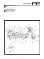
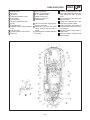
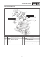
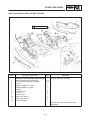
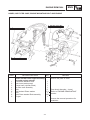
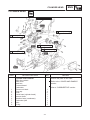
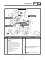
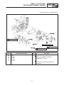
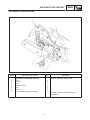
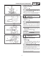
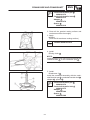
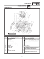
1
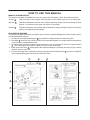
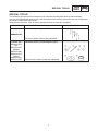
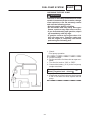
FOREWORD This Supplementary Service Manual has been prepared to introduce new service and data for the YP250. For complete service information procedures it is necessary to use this Supplementary Service Manual together with the following manual. YP250 SERVICE MANUAL: 4UC-AE1 YP250 (K) ’98 SUPPLEMENTARY SERVICE MANUAL: 4UC-AE2 YP250D ’98 SUPPLEMENTARY SERVICE MANUAL: 5DF-AE1 YP250 2000 SUPPLEMENTARY SERVICE MANUAL 1999 by Yamaha Motor Co., Ltd. 1999 by MBK Industrie First Edition, November 1999 Any reproduction or unauthorized use without the written permission of Yamaha Motor Co., Ltd. is expressly prohibited. EB001000 NOTICE This manual was produced by the Yamaha Motor Company primarily for use by Yamaha/MBK dealers and their qualified mechanics. It is not possible to include all the knowledge of a mechanic in one manual, so it is assumed that anyone who uses this book to perform maintenance and repairs on Yamaha/MBK scooter has a basic understanding of the mechanical ideas and the procedures of scooter repair. Repairs attempted by anyone without this knowledge are likely to render the scooter unsafe and unfit for use. Yamaha Motor Company, Ltd. is continually striving to improve all its models. Modifications and significant changes in specifications or procedures will be forwarded to all authorized Yamaha/MBK dealers and will appear in future editions of this manual where applicable. NOTE: Designs and specifications are subject to change without notice. IMPORTANT INFORMATION Particularly important information is distinguished in this manual by the following notations. The Safety Alert Symbol means ATTENTION! BECOME ALERT! YOUR SAFETY IS INVOLVED! WARNING CAUTION: NOTE: Failure to follow WARNING instructions could result in severe injury or death to the scooter operator, a bystander or a person inspecting or repairing the scooter. A CAUTION indicates special precautions that must be taken to avoid damage to the scooter. A NOTE provides key information to make procedures easier or clearer. YP002000 HOW TO USE THIS MANUAL MANUAL ORGANIZATION This manual consists of chapters for the main categories of subjects. (See “Illustrated symbols”) 1st title 1 : This is the title of the chapter with its symbol on the upper right corner of each page. 2nd title 2 : This title indicates the section of the chapter and only appears on the first page of each section. It is located in the upper left corner of the page. 3rd title 3 : This title indicates a sub-section that is followed by step-by-step procedures accompanied by corresponding illustrations. EXPLODED DIAGRAMS To heps identify parts and clarify procedure steps, there are exploded diagrams at start of each removal and disassembly section. 1. An easy-to-see exploded diagram 4 is provided for disassembly and assembly jobs. 2. Numbers 5 are given in the order of jobs in the exploded diagram. A number that is enclosed by a circle indicates a disassembly step. 3. An explanation of jobs and notes is presented in an easy-to-read way by the use of symbol marks 6 . The meanings of the symbol marks are given on the next page. 4. A job instruction chart 7 accompanies the exploded diagram, providing the order of jobs, names of parts, notes in jobs, etc. 5. For jobs requiring more information, the step-by-step format supplements 8 are given in addition to the exploded diagram and the job instruction chart. 2 1 4 5 8 6 6 7 3 EB003000 1 2 GEN INFO ILLUSTRATED SYMBOLS SPEC 3 4 INSP ADJ ENG 5 6 COOL CARB 7 1 2 3 4 5 6 7 8 9 General information Specifications Periodic inspection and adjustment Engine Cooling system Carburetion Chassis Electrical Troubleshooting 8 CHAS ELEC Illustrated symbols 10 to 17 are used to identify the specifications appearing in the text. 10 9 TRBL SHTG 11 12 13 14 15 Illustrated symbols 1 to 9 are designed as thumb tabs to indicate the chapter’s number and content. 16 10 11 12 13 14 15 16 17 Possible to maintain with engine mounted Filling fluid Lubricant Special tool Tightening Wear limit, clearance Engine speed Ω, V, A 17 Illustrated symbols 18 to 23 in the exploded diagrams indicate the types of lubricants and lubrication points. 18 19 20 21 22 23 18 19 20 21 22 23 Apply engine oil Apply gear oil Apply molybdenum disulfide oil Apply wheel bearing grease Apply lightweight lithium-soap base grease Apply molybdenum disulfide grease Illustrated symbols 24 to 25 in the exploded diagrams indicate the where to apply locking agent 24 and when to install new parts 25 . 24 25 24 Apply locking agent (LOCTITE) 25 Use new one CONTENTS GENERAL INFORMATION SCOOTER IDENTIFICATION . . . . . . . . . . . . . . . . . . . . . . . . . . . . . . . . VEHICLE IDENTIFICATION NUMBER (for E) . . . . . . . . . . . . . . . FRAME SERIAL NUMBER (except for E) . . . . . . . . . . . . . . . . . . . ENGINE SERIAL NUMBER . . . . . . . . . . . . . . . . . . . . . . . . . . . . . . . MODEL LABEL . . . . . . . . . . . . . . . . . . . . . . . . . . . . . . . . . . . . . . . . . . SPECIAL TOOLS . . . . . . . . . . . . . . . . . . . . . . . . . . . . . . . . . . . . . . . . . . . 1 1 1 1 1 2 SPECIFICATIONS GENERAL SPECIFICATIONS . . . . . . . . . . . . . . . . . . . . . . . . . . . . . . . . MAINTENANCE SPECIFICATIONS . . . . . . . . . . . . . . . . . . . . . . . . . . . ENGINE . . . . . . . . . . . . . . . . . . . . . . . . . . . . . . . . . . . . . . . . . . . . . . . . TIGHTNING TORQUES . . . . . . . . . . . . . . . . . . . . . . . . . . . . . . . . . . CHASSIS . . . . . . . . . . . . . . . . . . . . . . . . . . . . . . . . . . . . . . . . . . . . . . . TIGHTNING TORQUES . . . . . . . . . . . . . . . . . . . . . . . . . . . . . . . . . . ELECTRICAL . . . . . . . . . . . . . . . . . . . . . . . . . . . . . . . . . . . . . . . . . . . LUBRICATION POINTS AND GRADE OF LUBRICANT . . . . . . . . . ENGINE . . . . . . . . . . . . . . . . . . . . . . . . . . . . . . . . . . . . . . . . . . . . . . . . CHASSIS . . . . . . . . . . . . . . . . . . . . . . . . . . . . . . . . . . . . . . . . . . . . . . . CABLE ROUTING . . . . . . . . . . . . . . . . . . . . . . . . . . . . . . . . . . . . . . . . . . 3 6 6 8 10 11 13 15 15 16 17 PERIODIC INSPECTIONS AND ADJUSTMENTS INTRODUCTION . . . . . . . . . . . . . . . . . . . . . . . . . . . . . . . . . . . . . . . . . . . PERIODIC MAINTENANCE/LUBRICATION INTERVALS . . . . . . . . COVER AND PANEL . . . . . . . . . . . . . . . . . . . . . . . . . . . . . . . . . . . . . . . . SIDE COVER, SIDE COVER MOLE PASSENGER SEAT . . . . . RIDER SEAT AND MAIN BOX . . . . . . . . . . . . . . . . . . . . . . . . . . . . . SIDE COVER MOLE AND FOOTREST BOARD . . . . . . . . . . . . . COWLING, HANDLE COVER, METER ASSEMBLY . . . . . . . . . . LEGSHIELD AND FUEL TANK . . . . . . . . . . . . . . . . . . . . . . . . . . . . ENGINE . . . . . . . . . . . . . . . . . . . . . . . . . . . . . . . . . . . . . . . . . . . . . . . . . . . ENGINE OIL REPLACEMENT . . . . . . . . . . . . . . . . . . . . . . . . . . . . . CRANKCASE FILTER CLEANING . . . . . . . . . . . . . . . . . . . . . . . . . AIR INDUCTION SYSTEM INSPECTION . . . . . . . . . . . . . . . . . . . COOLANT REPLACEMENT . . . . . . . . . . . . . . . . . . . . . . . . . . . . . . ELECTRICAL . . . . . . . . . . . . . . . . . . . . . . . . . . . . . . . . . . . . . . . . . . . . . . HEADLIGHT BEAM ADJUSTMENT . . . . . . . . . . . . . . . . . . . . . . . . 26 26 28 28 29 31 32 33 34 34 35 36 37 40 40 ENGIVE OVERHAUL ENGINE REMOVAL . . . . . . . . . . . . . . . . . . . . . . . . . . . . . . . . . . . . . . . . . WIREHARNESS, CABLE AND REAR BRAKE . . . . . . . . . . . . . . . HOSES, AIR FILTER CASE, ENGINE MOUNTING BOLT AND ENGINE . . . . . . . . . . . . . . . . . . . . . . . . . . . . . . . . . . . . . . . . . . . . . CYLINDER HEAD . . . . . . . . . . . . . . . . . . . . . . . . . . . . . . . . . . . . . . . . . . 41 41 43 44 V BELT, CLUTCH AND SECONDARY/PRIMARY SHEAVE . . . . . . CRANKCASE FILTER COVER AND CRANKCASE COVER (LEFT) . . . . . . . . . . . . . . . . . . . . . . . . . . . . . . . . . . . . . . . . . . . . . . V BELT, CLUTCH AND SECONDARY/PRIMARY SHEAVE . . . . TRANSMISSION . . . . . . . . . . . . . . . . . . . . . . . . . . . . . . . . . . . . . . . . . . . AIR INDUCTION SYSTEM . . . . . . . . . . . . . . . . . . . . . . . . . . . . . . . . . . . CRANKCASE AND CRANKSHAFT . . . . . . . . . . . . . . . . . . . . . . . . . . . CRANKCASE REMOVAL . . . . . . . . . . . . . . . . . . . . . . . . . . . . . . . . . CRANKSHAFT REMOVAL . . . . . . . . . . . . . . . . . . . . . . . . . . . . . . . . CRANKSHAFT INSTALLATION . . . . . . . . . . . . . . . . . . . . . . . . . . . 46 46 47 49 51 52 52 52 52 COOLING SYSTEM RADIATOR . . . . . . . . . . . . . . . . . . . . . . . . . . . . . . . . . . . . . . . . . . . . . . . . 54 CARBURETOR CARBURETOR . . . . . . . . . . . . . . . . . . . . . . . . . . . . . . . . . . . . . . . . . . . . . 55 CARBURETOR DISASSEMBLY . . . . . . . . . . . . . . . . . . . . . . . . . . . . . . 56 THROTTLE POSITION SENSOR ADJUSTMENT . . . . . . . . . . . . 58 CHASSIS FRONT WHEEL . . . . . . . . . . . . . . . . . . . . . . . . . . . . . . . . . . . . . . . . . . . . SPEED SENSOR AND SENSOR ROTOR . . . . . . . . . . . . . . . . . . SPEED SENSOR AND THE SENSOR ROTOR . . . . . . . . . . . . . . SPEED SENSOR REMOVAL . . . . . . . . . . . . . . . . . . . . . . . . . . . . . . SPEED SENSOR AND SENSOR ROTOR INSPECTION . . . . . SPEED SENSOR ASSEMBLY . . . . . . . . . . . . . . . . . . . . . . . . . . . . . REAR WHEEL . . . . . . . . . . . . . . . . . . . . . . . . . . . . . . . . . . . . . . . . . . . . . REAR SHOCK ABSORBER AND SWINGARM . . . . . . . . . . . . . . . . . 59 59 60 60 60 61 64 65 ELECTRICAL ELECTRICAL COMPONENTS . . . . . . . . . . . . . . . . . . . . . . . . . . . . . . . CIRCUIT DIAGRAM . . . . . . . . . . . . . . . . . . . . . . . . . . . . . . . . . . . . . . . . . CHECKING SWITCHES . . . . . . . . . . . . . . . . . . . . . . . . . . . . . . . . . . . . . SWITCH POSITION AND TERMINAL CONNECTION . . . . . . . . CHECKING STEPS . . . . . . . . . . . . . . . . . . . . . . . . . . . . . . . . . . . . . . SWITCH CONNECTION AS SHOWN IN THIS MANUAL . . . . . . IGNITION SYSTEM . . . . . . . . . . . . . . . . . . . . . . . . . . . . . . . . . . . . . . . . . CIRCUIT DIAGRAM . . . . . . . . . . . . . . . . . . . . . . . . . . . . . . . . . . . . . . ELECTRIC STARTING SYSTEM . . . . . . . . . . . . . . . . . . . . . . . . . . . . . CIRCUIT DIAGRAM . . . . . . . . . . . . . . . . . . . . . . . . . . . . . . . . . . . . . . LIGHTING SYSTEM . . . . . . . . . . . . . . . . . . . . . . . . . . . . . . . . . . . . . . . . CIRCUIT DIAGRAM . . . . . . . . . . . . . . . . . . . . . . . . . . . . . . . . . . . . . . TROUBLESHOOTING . . . . . . . . . . . . . . . . . . . . . . . . . . . . . . . . . . . SIGNAL SYSTEM . . . . . . . . . . . . . . . . . . . . . . . . . . . . . . . . . . . . . . . . . . CIRCUIT DIAGRAM . . . . . . . . . . . . . . . . . . . . . . . . . . . . . . . . . . . . . . TROUBLESHOOTING . . . . . . . . . . . . . . . . . . . . . . . . . . . . . . . . . . . SIGNAL SYSTEM CHECK . . . . . . . . . . . . . . . . . . . . . . . . . . . . . . . . 66 67 69 69 70 70 71 71 72 72 73 73 74 80 80 81 83 FUEL PUMP SYSTEM . . . . . . . . . . . . . . . . . . . . . . . . . . . . . . . . . . . . . . CIRCUT DIAGRAM . . . . . . . . . . . . . . . . . . . . . . . . . . . . . . . . . . . . . . FUEL PUMP CIRCUIT OPERATION . . . . . . . . . . . . . . . . . . . . . . . TROUBLESHOOTING . . . . . . . . . . . . . . . . . . . . . . . . . . . . . . . . . . . CHECKING THE FUEL PUMP . . . . . . . . . . . . . . . . . . . . . . . . . . . . WIRING DIAGRAM 89 89 90 91 93 SCOOTER IDENTIFICATION GEN INFO YP100000 GENERAL INFORMATION SCOOTER IDENTIFICATION YP100010 VEHICLE IDENTIFICATION NUMBER (for E) The vehicle identification number 1 is stamped into the right side of the frame. NOTE: The vehicle identification number is used to identify your scooter and may be used to register your scooter with the licensing authority in your country. YP100020 FRAME SERIAL NUMBER (except for E) The frame serial number 1 is stamped into the right side of the frame. EB100030 ENGINE SERIAL NUMBER The engine serial number is stamped into the crankcase. NOTE: Designs and specifications are subject to change without notice. MODEL LABEL The model label is affixed under the seat. This information will be needed to order spare parts. 1 SPECIAL TOOLS GEN INFO EB102000 SPECIAL TOOLS The following special tools are necessary for complete and accurate tune-up and assembly. Use only the appropriate special tools; this will help prevent damage caused by the use of inappropriate tools or improvised techniques. When placing an order, refer to the list provided below to avoid any mistakes. Tool No. Tool name/Usage Crankcase separating tool 90890-01135 This tool is used to remove the crankshaft. Installer pot 90890-01274 Bolt 90890-01275 Adaptor 90890-01280 90890-01478 Spacer 90890-01016 90890-01288 Crankshaft installer pot/bolt/adapter/spacer These tools are used to install the crankshaft. 2 Illustration SPEC GENERAL SPECIFICATIONS SPECIFICATIONS GENERAL SPECIFICATIONS Model YP250 Model code: 5GM2, 5GM3 Dimensions: Overall length Overall width Overall height Seat height Wheelbase Minimum ground clearance Minimum turning radius 2,140 mm ,780 mm 1,350 mm ,730 mm 1,535 mm ,120 mm 2,700 mm Basic weight: With oil and full fuel tank 168 kg Engine: Engine type Cylinder arrangement Displacement Bore stroke Compression ratio Compression pressure (STD) Starting system Lubrication system: Liquid-cooled 4-stroke, SOHC Forward-inclined single cylinder 0.249L (249 cm3) 69.0 66.8 mm 10 : 1 1,400 kPa (14 kg/cm2, 14 bar) at 500 r/min Electric starter Wet sump Oil type or grade: Engine oil API STANDERD: SE or higher grade Periodic oil change Total amount Transmission oil Total amount 1.2 L 1.4 L 0.25 L Radiator capacity: Total amount (including all routes) 1.4 L Air filter: Carburetor side Crankcase side Wet type element Dry type element Fuel: Type Fuel tank capacity Regular unleaded gasoline 12 L 3 GENERAL SPECIFICATIONS Model SPEC YP250 Carburetor: Type/quantity Manufacturer Y28V-1E/1 TEIKEI Spark plug: Type Manufacturer Spark plug gap DR8EA NGK 0.6 X 0.7 mm Clutch type: Dry, centrifugal automatic Transmission: Primary reduction system Primary reduction ratio Secondary reduction system Secondary reduction ratio Transmission type Operation Single speed automatic Helical gear 40/15 (2.666) Helical gear 38/15 (2.533) Single speed automatic (V-belt type) Centrifugal automatic type 2.44 X 0.83:1 Chassis: Frame type Caster angle Trail Steel tube underbone 28 103 mm Tire: Type Size Manufacturer Type Tubeless 110/90-12 64L 130/70-12 62L IRC/MICHELN IRC/MICHELN MB67/BOPPER MB67/BOPPER front rear front rear front rear Tire pressure (cold tire): Maximum load-except motorcycle Loading condition A* front rear Loading condition B* front rear High-speed riding front rear 187 kg 0 X 90 kg 175 kPa (1.75 kg/cm2, 1.75 bar) 200 kPa (2.0 kg/cm2, 2.0 bar) 90 X 205 kg 200 kPa (2.0 kg/cm2, 2.0 bar) 225 kPa (2.25 kg/cm2, 2.25 bar) 200 kPa (2.0 kg/cm2, 2.0 bar) 225 kPa (2.25 kg/cm2, 2.25 bar) *Load is the total weight of cargo, rider, passenger, and accessories. 4 GENERAL SPECIFICATIONS Model Brake: Front brake Rear brake YP250 Single disc brake Right hand operation Single disc brake Left hand operation type operation type operation Suspension: Front suspension Rear suspension Telescopic fork Unit swing Shock absorber: Front shock absorber Rear shock absorber Coil spring/Oil damper Coil spring/Oil damper Wheel travel: Front wheel travel Rear wheel travel 100 mm 90 mm Electrical: Ignition system Generator system Battery type Battery capacity T.C.I. (Digital) A.C. magneto GT7B-4 12 V 6.5 AH Headlight type: Quartz bulb (Halogen) Bulb wattage quantity: Headlight (High) Headlight (Low) Auxiliary light Tail/brake light Flasher light (Front) Flasher light (Rear) Meter light High beam indicator light Oil indicator light Turn indicator light License light 12 V 60 W/55 W 1 12 V 55 W 1 12 V 5 W 1 12 V 5 W/21 W 2 12 V 21 W 2 12 V 16 W 2 12 V 1.7 W 3 12 V 1.7 W 1 12 V 1.7 W 1 12 V 3.4 W 2 12 V 5 W 1 5 SPEC MAINTENANCE SPECIFICATIONS SPEC MAINTENANCE SPECIFICATIONS ENGINE Item Standard Limit Cylinder head: Warp limit 0.05 mm Cam chain: Cam chain type/No. of links Cam chain adjustment method DID SCA-0404A SDH/104 Automatic Automatic centrifugal clutch: Clutch shoe thickness Clutch housing inside diameter Clutch shoe spring free length Weight outside diameter Clutch – in revolution Clutch – stall revolution 3.3 mm 135 mm 28.1 mm 20 mm 2,250 2,850 r/min 3,700 4,700 r/min 2.0 mm 135.5 mm 19.5 mm V-belt: V-belt width 22.6 mm 21.0 mm Carburetor: Type I.D. mark Ventuly outside diameter Main jet Main air jet Jet needle Throttle valve size Pilot air jet Needle jet Pilot outlet Pilot jet Bypass Pilot screw Valve seat size Starter jet 1 Starter jet 2 Float height Engine idle speed Intake vacuum Oil temperature Cooling water temperature Y28V-1E/1 5GM 10 ø28 #128 ø0.9 5D9B-3/5 11 ø1.2 #85 ø0.8 #43 0.7 3 1 2 2 1.4 ø0.5 ø0.5 26.5 27.5 mm 1,300 1,500 r/min 29.3 36.0 kPa (220 270 mmHg) 65 75C 80C Electrical 2GV/MITSUBISHI Fuel pump: Type Model/manufacturer (M.J) (M.A.J) (J.N) (Th.V) (P.A.J.1) (N.J) (P.O) (P.J) (B.P) (P.S) (V.S) (G.S.1) (G.S.2) (F.H) 6 MAINTENANCE SPECIFICATIONS Item Radiator: Type Width/height/thickness Radiator cap opening pressure Radiator capacity Reservoir tank capacity SPEC Standard Limit Cooling fin with electric fan 140/238/24 mm 110 140 kPa (1.1 1.4 kg/cm2, 1.1 1.4 bar) 1.4 L 0.4 L 7 MAINTENANCE SPECIFICATIONS SPEC TIGHTENING TORQUES ENGINE Part to be tightened g Oil check bolt Exhaust pipe stud bolt Air induction system pipe stud bolt Spark plug Cam sprocket cover Cylinder head and cylinder Cylinder head and cylinder (Cam chain side) Valve cover Rotor Valve adjuster locknut Cam shaft bearing stopper Cam sprocket Cam chain tensioner (Body) (Plug) Guide stopper 2 Water pump housing cover Hose joint Thermostatic valve cover Filler neck supporting Oil pump Oil pump cover Oil strainer cover Carburetor joint Carburetor joint and carburetor Air filter assembly Air filter cover Exhaust pipe assembly Muffler Muffler and exhaust pipe Protector (Exhaust pipe) Protector (Muffler end cap) Air induction system pipe Air induction system assembly Air induction system air filter assembly Crankcase (left and right) Drain bolt (Engine oil) Drain bolt (Transmission oil) Oil filler Transmission case cover Crankcase cover (left) Crankcase filter cover Crankcase cover protector Crankcase cover protector Magnet cover Thread size Q’ty y — — — — Bolt Nut Bolt M6 M8 M6 M12 M6 M8 M6 Bolt Nut Nut Bolt Bolt Bolt Bolt Bolt Bolt — Bolt Bolt Screw Bolt Bolt Bolt Nut Bolt Screw Nut Bolt Bolt Screw Screw Nut Bolt Bolt Bolt Bolt Bolt Bolt Bolt Bolt — Bolt Screw — Part name 8 Tightening torque Nm mkg 1 2 2 1 2 4 2 7 13 10 18 10 22 10 0.7 1.3 1.0 1.8 1.0 2.2 1.0 M6 M16 M6 M6 M10 5 1 2 2 1 10 80 14 8 60 1.0 8.0 1.4 0.8 6.0 M6 M8 M6 M6 M6 M6 M5 M6 M3 M35 M6 M6 M6 M5 M8 M10 M8 M6 M6 M6 M6 M6 M6 M12 M8 M14 M8 M6 M5 M6 M6 M6 2 1 1 3 2 2 1 2 1 1 2 2 2 7 2 3 1 2 3 2 2 2 9 1 1 1 6 8 3 1 3 10 10 8 10 10 7 10 5 7 1 32 10 10 7 1 20 53 14 10 10 12 10 7 10 20 22 3 16 10 1.2 7 7 10 1.0 0.8 1.0 1.0 0.7 1.0 0.5 0.7 0.1 3.2 1.0 1.0 0.7 0.1 2.0 5.3 1.4 1.0 1.0 1.2 1.0 0.7 1.0 2.0 2.2 0.3 1.6 1.0 0.12 0.7 0.7 1.0 Remarks MAINTENANCE SPECIFICATIONS Part to be tightened g Cover (oil pump) Timing check plug One way clutch Clutch housing Grease stopper (Primary sheave) Primary fixed sheave Clutch carrier assembly Stator Pick up coil Starter motor Thermo switch Thermo unit Part name Bolt Plug — Bolt — — — — — Bolt — — 9 Thread size Q’ty y M6 M16 M8 M14 M4 M14 M36 M6 M5 M6 M18 Pt 1/8 2 1 3 1 4 1 1 3 2 2 2 1 SPEC Tightening torque Nm mkg 12 8 30 60 3 80 90 10 7 10 23 8 1.2 0.8 3.0 6.0 0.3 8.0 9.0 1.0 0.7 1.0 2.3 0.8 Remarks MAINTENANCE SPECIFICATIONS SPEC CHASSIS Item Standard Limit Front suspension: Front fork travel Fork spring free length Spring rate (K1) Spring rate (K2) Stroke (K1) Stroke (K2) Oil capacity Oil level Oil grade Inner tube vend limit 100 mm 268 mm 4.82 N/mm (0.49 kg/mm) 8.84 N/mm (0.9 kg/mm) 0 40 mm 40 100 mm 0.142 L (142 cm3) 80 mm Fork oil 15 WT or equivalent 263 mm 0.2 mm Rear suspension: Shock absorber stroke Spring free length Spring rate (K1) (K2) (K3) Stroke (K1) (K2) (K3) 106 mm 262 mm 7.57 N/mm (0.77 kg/mm) 14 N/mm (1.43 kg/mm) 26.39 N/mm (2.69 kg/mm) 0 40 mm 40 70 mm 70 106 mm 257 mm Rear disk brake: Type Disc outside diameter thickness Pad thickness Master cylinder inside diameter Caliper cylinder outside diameter Brake fluid type Single 230 5 mm 5.3 mm 11 mm 22.2 mm 2 DOT #4 0.8 mm 2 5 mm 2 5 mm 3 5 mm Brake lever: Brake lever free play (front at lever side) Brake lever free play (rear) Throttle cable free play 10 MAINTENANCE SPECIFICATIONS SPEC TIGHTENING TORQUES CHASSIS Thread size Part to be tightened g Frame and engine bracket Engine bracket, compression rod and engine Compression rod and frame Sidestand (bolt and frame) Sidestand (bolt and nut) Rear footrest bracket Swingarm Rear shock absorber and frame Rear shock absorber and engine Steering ring nut Handle holder and steering shaft Handle upper holder and lower holder Brake hose and master cylinder Fuel tank (font) (rear) Fuel sender Filter Roll over valve Box Box (Bracket) Standing handle Sheet lock assembly Plastic parts & cover Cowling stay Cowling body Footrest board Headlight assembly Tail light assembly Front wheel axle and nut Rear wheel axle and nut Front brake caliper and front fork Brake disc and hub Brake hose and caliper Brake caliper and bleed screw Rear brake caliper and swingarm Speed sensor and sensor housing Windscreen 11 Tightening torque Nm mkg M12 1.25 M10 1.25 M10 1.25 M10 1.25 M10 1.25 M 6 1.0 M 8 1.25 M10 1.25 M 8 1.25 M25 1.0 M20 1.5 M 8 1.25 M10 1.25 59 32 64 40 40 7 35 40 20 22 155 23 30 5.9 3.2 6.4 4.0 4.0 0.7 3.5 4.0 2.0 2.2 15.5 2.3 3.0 M 6 1.0 M 6 1.0 M 5 0.8 M 6 1.0 M 5 0.8 M 6 1.0 M 8 1.25 M 8 1.0 M 6 1.0 M 5 1.0 M 8 1.25 M 6 1.0 M 6 1.0 M 6 1.0 M 6 1.0 M14 1.5 M14 1.5 M10 1.25 M 8 1.25 M10 1.25 M 7 1.0 M10 1.25 M 8 1.25 M 5 1.0 10 7 3 7 4 10 16 16 10 2 16 7 7 7 7 70 135 50 23 30 6 40 23 0.4 1.0 0.7 0.3 0.7 0.4 1.0 1.6 1.6 1.0 0.2 1.6 0.7 0.7 0.7 0.7 7.0 13.5 5.0 2.3 3.0 0.6 4.0 2.3 0.04 Remarks See “NOTE” MAINTENANCE SPECIFICATIONS SPEC NOTE: 1. First, tighten the ring nut (lower) approximately 38 Nm (3.8 mkg) by using the torque wrench, then loosen the ring nut 1/4 turn. 2. Second, tighten the ring nut (lower) approximately 22 Nm (2.2 mkg) by using the torque wrench, then finger tighten the ring nut (center). Align the slots both ring nut and install the lock washer. 3. Final, hold the ring nuts (lower and center) and tighten the ring nut (upper) 75 Nm (7.5 mkg) by using the torque wrench. 12 MAINTENANCE SPECIFICATIONS SPEC ELECTRICAL Item Standard limit Ignition timing: Ignition timing (B.T.D.C.) Advanced timing (B.T.D.C.) Advanced type 10_ at 1,400 r/min 32_ at 5,000 r/min Electrical type ::: ::: ::: 189 231 Ω at 20_C/ Yellow – Blue J4T117/MITSUBISHI ::: ::: ::: Ignition coil: Model/manufacturer Minimum spark gap Primary winding resistance Secondary winding resistance F6T507 /MITSUBISHI 6 mm 3.6 4.8 Ω at 20_C 10.7 14.5 kΩ at 20_C ::: ::: ::: ::: Spark plug cap: Type Resistance Resin type 10 kΩ ::: ::: A.C. magneto F4T370 /MITSUBISHI 14 V 19.5 A at 5,000 r/min 0.37 0.45 Ω at 20_C/ White – White ::: ::: ::: ::: ::: SH640A-12/SHINDENGEN 14.1 14.9 V 18 A 200 V ::: ::: ::: ::: Constant mesh type ::: SM-13/MITSUBA/SM-13454 12 V 0.65 kW 0.0017 0.0027 Ω at 20_C 10 mm 2 pcs. 8.82 N (899 g) 28 mm 0.7 mm ::: ::: ::: ::: 4 mm ::: 570 g 27 mm ::: T.C.I.: Pickup coil resistance/color T.C.I. unit model/manufacturer Charging system: Type Model/manufacturer Normal output Stator coil resistance/color Rectifire/regulator: Model/manufacturer No load regulated voltage Capacity Withstand voltage Electric starter system: Type Starter motor: Model/manufacturer /ID number Operation voltage Output Armature coil resistance Brush overall length Brash quantity Spring force Commutator diameter Mica undercut (depth) 13 MAINTENANCE SPECIFICATIONS SPEC Item Standard limit Starter relay: Model/manufacturer Amperage rating Coil winding resistance MS5F-421 /JIDECO 180 A 4.2 X 4.6 Ω at 20_C ::: ::: ::: Horn: Model/manufacturer Maximum amperage YF-12/NIKKO 3A ::: ::: Flasher/hazard relay Type Model/manufacturer Flasher frequency Full transistor type FE246BH/DENSO 75 X 95 cycle/min ::: ::: ::: Fuel gage: Model/manufacturer Sender unit resistance – full Sender unit resistance – empty 5GM/NIPPON SEIKI 4 X 10 Ω 90 X 100 Ω ::: ::: ::: Starting circuit cut-off relay: Model/manufacturer Coil winding resistance ACA12115-1/MATSUSHITA 72 X 88 Ω ::: ::: Electric fan motor: Model/manufacturer 5GM/MITSUBA ::: Thermo switch (electric fan): Model/manufacturer 5GH/NIHON THERMOSTAT ::: Thermo switch (auto choke): Model/manufacturer 5GM/NIHON THERMOSTAT ::: Thermo unit: Model/manufacturer 46X/NIPPON SEIKI ::: Circuit breaker: Type MAIN HEAD LIGHT SIGNALING SYSTEM IGNITION RADIATOR BACK UP Reserve Reserve Reserve Reserve Fuse 30 A 1 pc. 15 A 1 pc. 15 A 1 pc. 7.5 A 1 pc. 4A 1 pc. 10 A 1 pc. 30 A 1 pc. 15 A 1 pc. 10 A 1 pc. 7.5 A 1 pc. ::: ::: ::: ::: ::: ::: ::: ::: ::: ::: ::: 14 LUBRICATION POINTS AND GRADE OF LUBRICANT SPEC LUBRICATION POINTS AND GRADE OF LUBRICANT ENGINE Lubrication Point Symbol Oil seal lips O-ring (Except V-belt drive unit) Cylinder head tightening nut mounting surface Crankshaft pin outside Connecting rod big end thrust surface Rotary filter inner surface Drive gear inner surface Cam chain outside sprocket inner surface Piston pin Piston outside and ring groove Camshaft cam profile Valve stem (IN, EX) Valve stem end (lN, EX) Rocker shaft Valve rocker arm inner surface Shaft Shaft (Oil pump assembly) Gasket (Oil pump assembly) Holder Idle gear 1 thrust surfaces Shaft 1 Idle gear 2 thrust surfaces Idle gear 2 inner surface Main axle thrust surfaces Crankcase mating surfaces Yamaha bond No. 1215 Crankcase breather plug Stator grommet Yamaha bond No. 1215 Suction pipe 15 LUBRICATION POINT AND GRADE OF LUBRICANT SPEC CHASSIS Lubrication Point Symbol Front wheel oil seal lips (left/right) Swingarm oil seal lips (left/right) Steering head pipe bearing (upper/lower) Steering head pipe dust seal lips (upper/lower) Tube guide (throttle grip) inner surface Brake lever and lever holder bolt sliding surface Sidestand sliding surface Centerstand sliding surface and mounting bolt Centerstand stopper pivot shaft 16 CABLE ROUTING SPEC CABLE ROUTING 1 2 3 4 5 6 7 8 9 10 11 12 13 14 Speed sensor Front brake hose Throttle cable Relay Brake hose assembly Thermo switch lead Fan motor lead Switch assembly Carburetor fuel drain hose Carburetor coolant drain hose Carburetor air ventilation hose Coolant pipe Sidestand switch Ignitor unit 15 16 17 18 19 20 21 22 23 24 Frame Seat lock cable Footrest board Handlebar Handlebar under cover Handlebar upper cover Right handlebar switch lead Front brake switch lead Left handlebar switch lead Rear brake switch lead 17 A Route the brake hose assembly through the guide on the handlebar. B Fasten the front brake hose, brake hose assembly throttle cable to the frame with a plastic band. C Fasten the brake hose assembly, throttle cable to the frame with a band and the end of band is backward. CABLE ROUTING SPEC D Clamp the brake hose assembly. I Throttle cable pull side. (White P Fasten the wire harness to the E Fasten the seat lock cable nut) frame with a band and the end of throttle cable and wireharness to J Throttle cable push side. (Black band inside. the frame with a band, and the and white nut) Q Roll the tape because of fix the end of band is downward. K Clamp the fuel hose. protection tube to the fuel pum F Clamp the switch assembly lead L Route the carburetor coolant lead. with a band and cut the end of drain hose, carburetor fuel drain R Clamp the fuel pump lead and band. It’s downward. hose through the clamp. sidestand switch lead. G Fasten the throttle cable with a M Route the carburetor drain hose S Fasten the throttle cable and the band and more than 10 mm through the centerstand spring end of band backward. between throttle cable and box. hook. T Lubricate the silicone grease H Don’t scrub each other when fix N Clamp the sidestand switch befor fasten the cable and the throttle cables. lead. hoses. O Touch the protection tube on the fuel pump. 18 CABLE ROUTING U More than 10 mm. A’ Fasten the left handlebar switch V Route the seat lock cable lead and rear brake switch lead through the footrest board. to the handlebar with a plastic W Route the left handlebar switch locking tie, cut the end of locking lead through front side of the tie at 5 mm or less. handlebar under cover. B’ Don’t catch the seat lock cable X Route the right handlebar switch between footrest board and box. lead through the clamp. Y Route the front brake hose through the right hole of handlebar under cover. Z Route the brake hose assembly through the left hole of the handlebar under cover. 19 SPEC CABLE ROUTING 1 2 3 4 5 6 7 8 9 10 11 12 Box light Rectifire/ regulator Air induction system air filter Wireharness Battery negative lead Battery positive lead Seat lock cable assembly Battery Rodiator reservoir tank Ignition coil Air induction system Engine ground 13 14 15 16 Engine bracket Rear brake hose A. C. magneto lead Starter motor lead A Fasten the wireharness to the frame with a plastic locking tie. B Route the brake hose assembly through the clamp of engine bracket. C Fix the seat lock to the box. 20 SPEC D Fasten the wireharness to the frame with a plastic locking tie. E Clamp the rear brake hose. F Clamp the wireharness to the frame with a plastic locking tie. G Fasten the seat lock cable and wireharness with a band and band of the end on inside of the frame. CABLE ROUTING SPEC H Fasten the wireharness to the M Clamp the speed sensor lead to Q Clamp the speed sensor lead the front brake hose. Position the and that caliper tightning bolt frame with a band and the band clamp (locatio of the speed senand clamp in parallel with front of end on inside of the frame. sor) to front of the upper clamp fork. I Clamp the radiator reservoir and another clamps to outside. R Fix the starter relay to the foothose. rest board. J Fasten the wireharness to the N Through the speed sensor lead between front brake caliper and S Clamp the radiator reservoir stay with a band and the end of bolt. hose and starter motor lead to band on rearside. the frame with a plastic clamp. K Fasten the speed sensor lead to O Route the speed sensor lead through the guide. T Fix the fuse box to the footrest the stay. board. L Route the front speed sensor P When pull the speed sensor lead. Don’t loose. U Fasten the rodiator reservoir lead and front brake hose hose and starter motor lead on through the clamp on the frame. the frame with a plastic clamp. (front side: speed sensor lead rear side: front brake hose) 21 CABLE ROUTING V Fix the turn signal relay on the footboard. W Fasten the starter motor lead and engine ground lead on the frame with the plastic clamp. X Route the parking cable and rear brake hose through the guide. Y Clamp the A. C. magneto. 22 SPEC CABLE ROUTING Air filter case Seat lock Tensioner Crankcase breather hose Fuel sender Throttle cable Seat lock cable assembly Panel Footrest board Radiator resorvoir tank breather hose 11 Vacuum hose 12 Throttle position sensor lead 13 Seat lock 1 2 3 4 5 6 7 8 9 10 D Fasten the wireharness on the frome with a band and the end of band match the tank rail pipe angle. E Fix the seat lock cable along the guide of panel. F Fasten the wireharness on the frame with a plastic clamp. A Don’t turn the idle adjust screw, G Fasten the starter motor lead on when fix the hose. the fuel tank brocket with a plasB Route the gray seat lock outer tic locking tie. cable through the left side of H Route the starter relay lead toframe. ward inside. C Set the fuel tank sender lead and I Route the battery negative lead sub lead. toward inside. 14 15 16 17 18 19 Auto choke lead Brake hose assembly A. C. magneto lead Starter motor lead Engine ground lead Wireharness SPEC 23 CABLE ROUTING J Route the thermo unit lead through the shortest distance and dont roll another lead but loose the thermounit lead. K Route the black seat lock cable outer through right side of frame. L Fasten the A. C. magneto lead starter motor lead and engine ground lead to the clamp on the engine bracket. M Route the crankcase breather hose into the hole of air filter case. 24 SPEC CABLE ROUTING 1 2 3 4 5 6 7 8 9 10 11 12 13 14 15 Front right turn signal light Relay Front left turn signal light Front brake hose assembly Horn lead (Hi) Horn (Hi) Throttle cable Speed sensor lead Front brake hose Horn (Lo) Stay Seat lock cable Leg sealed Seat lock cable assembly Inner fender 16 Panel 17 Auxiliary light lead A Don’t loosen the break hose when fix the break hose. B Route the speed sensor lead through the brake hose holder. C Fix the front brake hose on the front brake hose holder. D Align the white mark H of headlight assembly with the white tape of coupler lead E Install in stay 1 F To the headlight assembly G Clamp near the caupler side root of auxiliary light lead. 25 SPEC INTRODUCTION/ PERIODIC MAINTENANCE/LUBRICATION INTERVALS INSP ADJ EB300000 PERIODIC INSPECTIONS AND ADJUSTMENTS INTRODUCTION This chapter includes all information necessary to perform recommended inspections and adjustments. These preventive maintenance procedures, if followed, will ensure more reliable vehicle operation and a longer service life. The need for costly overhaul work will be greatly reduced. This information applies to vehicles already in service as well as to new vehicles that are being prepared for sale. All service technicians should be familiar with this entire chapter. YP301000 PERIODIC MAINTENANCE/LUBRICATION INTERVALS No No. 1 ITEM * Fuel line CHECKS AND MAINTENANCE JOB Check fuel hoses and vacuum hose for cracks or damage. Replace if necessary. 2 Fuel filter Check condition. Replace if necessary. 3 Spark plug Check condition. Clean, regap or replace if necessary. 4 * Valves Initial (1,000 km) EVERY 10,000 km Check valve clearance. Adjust if necessary. Air filter Clean or replace if necessary. V-belt case air filter Clean or replace if necessary. 7 * Front brake Check operation, fluid level and vehicle for fluid leakage. Correct accordingly. Replace brake pads if necessary. 8 * Rear brake Check operation, fluid level and vehicle for fluid leakage. Correct accordingly. Replace brake pads if necessary. 9 * Brake hoses Check for cracks or damage. Replace if necessary. 10 * Wheels Check balance, runout and for damage. Rebalance or replace if necessary. 11 * Tires 12 * Wheel bearings Check bearing for looseness or damage. Replace if necessary. Check tread depth and for damage. Replace if necessary. Check air pressure. Correct if necessary. Check bearing play and steering for roughness. Correct accordingly. Lubricate with lithium soap base grease. 15 Sidestand / centerstand Make sure that all nuts, bolts and screws are properly tightened. Tighten if necessary. Check operation. Lubricate and repair if necessary. 16 * Sidestand switch Check operation. Replace if necessary. 17 * Front fork Check operation and for oil leakage. Correct accordingly. Check operation and shock absorbers for oil leakage. Replace shock absorber assembly if necessary. 18 * Rear shock absorber assemblies 6 14 * Chassis fasteners 19 * Carburetor Check engine idling speed and starter operation. Adjust if necessary. 20 Check oil level and vehicle for oil leakage. Correct if necessary. Change. (Warm engine before draining.) Replace every 3,000 km 21 * Engine oil strainer Clean or replace if necessary. Clean or replace every 6,000 km g sys e 22 * Coo Cooling system Check coolant level and vehicle for coolant leakage. Correct if necessary. Engine oil Final gear oil 24 * V-belt Change coolant. 23 ANNUAL CHECK 5 13 3 * S Steering ee g bea bearings gs 20,000 km Check oil level and vehicle for oil leakage. Change oil. Replace. 26 INSP ADJ PERIODIC MAINTENANCE/LUBRICATION INTERVALS No No. ITEM CHECKS AND MAINTENANCE JOB 25 * Front / Rear brake switch Check operation. Adjust or replace if necessary. 26 Moving parts and cables Lubricate if necessary. 27 * Electrical components Check all lights, signals and switches function. Correct if necessary. Adjust headlight beam if necessary. *: EVERY Initial (1,000 km) 10,000 km 20,000 km ANNUAL CHECK Since these items require special tools, data and technical skills, they should be serviced by a Yamaha dealer. EAU02970 NOTE: The annual checks must be performed once a year unless a 10,000 km or 20,000 km maintenance was performed in the same year. The air filter needs more frequent service if you are riding in unusually wet or dusty areas. Hydraulic brake system When disassembling the master cylinder or caliper, always replace the brake fluid. Check the brake fluid level regularly and fill as required. Replace the oil seals on the inner parts of the master cylinder and caliper every two years. Replace the brake hoses every four years or if cracked or damaged. 27 COVER AND PANEL INSP ADJ COVER AND PANEL SIDE COVER, SIDE COVER MOLE, PASSENGER SEAT 16 Nm (1.6 mkg) 8 Nm (0.8 mkg) Order 1 2 3 4 5 6 7 Job name/Part name Q’ty Remarks Remove the parts in order. Side cover, Side cover panel and passenger seat removal Passenger seat Standing handle Side cover mole 3 Cap 1 Cap 2 Side cover 1 Side cover 2 1 1 1 1 1 1 1 Reverse the removal procedure for installation. 28 COVER AND PANEL INSP ADJ RIDER SEAT AND MAIN BOX 13 Nm (1.3 mkg) 16 Nm (1.6 mkg) 7 Nm (0.7 mkg) Order Job name/Part name Q’ty Remarks Remove the parts in order 1 2 3 4 5 6 Rider seat and main box removal Fuel tank cap Cover Rider seat Side cover 3 Clip Damper assembly 1 1 1 1 1 1 7 Coupler (Seat switch lead) 1 8 9 Pin Bottom plate 1 1 29 NOTE: Install the damper assembly to the body with its rod side backward and labels up ward. NOTE: Disconnect the couplers. COVER AND PANEL INSP ADJ RIDER SEAT AND MAIN BOX 13 Nm (1.3 mkg) 16 Nm (1.6 mkg) 7 Nm (0.7 mkg) Order Job name/Part name Q’ty 10 11 Bracket Coupler (Main box light read) 1 1 12 13 Seat lock Main box 2 1 Remarks NOTE: Disconnect the couplers. Reverse the removal procedure for installation. 30 COVER AND PANEL INSP ADJ SIDE COVER MOLE AND FOOTREST BOARD 7 Nm (0.7 mkg) Order 1 2 3 4 5 6 7 8 9 10 11 12 Job name/Part name Q’ty Side panel and footrest board removal 1/1 Mat (footrest board) (left/right) 1/1 Cover (footrest board) (left/right) 1 Cover 2 1 Battery negative (–) lead 1 Battery positive (+) lead 1 Battery 1 Flasher relay 1 Fuse box 1 Starter relay 1 Side cover mole 1 1 Side cover mole 2 1 Footrest board Remarks Remove the parts in order. Reverse the removal procedure for installation. 31 COVER AND PANEL INSP ADJ COWLING, HANDLE COVER, METER ASSEMBLY 7 Nm (0.7 mkg) Order Job name/Part name 1 2 3 4 5 6 7 8 9 10 Cowling, handle cover, meter assembly removal Upper cover Wind screen Inner panel Meter assembly Coupler (Meter lead) Cowling body Handle cover Coupler (headlight lead) Coupler (front flasher light lead (left)) Coupler (front flasher light lead (right)) Q’ty Remarks Remove the parts in order. 1 1 1 1 1 1 1 2 1 1 NOTE: Disconnect the couplers. NOTE: Disconnect the couplers. Reverse the removal procedure for installation. 32 COVER AND PANEL INSP ADJ LEGSHIELD AND FUEL TANK 10 Nm (1.0 mkg) 7 Nm (0.7 mkg) 16 Nm (1.6 mkg) 7 Nm (0.7 mkg) Order 1 2 3 4 5 6 7 8 9 Job name/Part name Q’ty Remarks Remove the parts in order. Legshield and fuel tank removal Legshield Inner fender Front under braket Fuel tank braket Fuel hose Coupler (fuel sensor lead) Fuel tank Rivet Cover 1 1 1 1 1 1 1 1 1 NOTE: Disconnect the couplers. Revers the removal procedure for installation. 33 ENGINE OIL REPLACEMENT INSP ADJ ENGINE ENGINE OIL REPLACEMENT 1. Start the engine and let it warm up for several minutes. 2. Turn off the engine and place an oil pan under the engine. 3. Remove: Drain plug 1 Gasket Drain the crankcase of its oil. 4. Install: Gasket New Drain plug 1 20 Nm (2.0 mkg) 5. Fill: Crankcase Oil quantity: 1.4 L 6. Check: Engine oil level Refer to “ENGINE OIL LEVEL INSPECTION” section. 7. Reset: Engine oil indicator circuit Resetting steps: Turn the main switch to on. Push and hold in the reset button for 2 to 5 seconds. Release the reset button 1 and the oil indicator light will go off. NOTE: If the oil is changed before the oil indicator light comes on (i.e. before the 3,000 km oil change interval is reached), be sure to reset the oil indicator light after changing the oil, so that it will come on at the correct time to indicate the next 3,000 km oil replacement. To reset the oil indicator light before it comes on: Release the reset button and the oil indicator light will come on for 1.4 seconds. 34 CRANKCASE FILTER CLEANING INSP ADJ CRANKCASE FILTER CLEANING 1. Remove: Crankcase filter cover 1 Crankcase filter cover seal Crankcase filter element NOTE: When installing the element in its case, besure its sealing surface matches the sealing surface of the case so there is no air leak. 2. Inspect: Crankcase filter element Damaged Replace. CAUTION: This element is a dry type. Be careful not to stain with grease or water. 3. Clean: Crankcase filter element 1 Blow out the dust in the element from the outer surface using compressed air. 4. Install: Crankcase filter element Crankcase filter cover seal Crankcase filter cover 7 Nm (0.7 mkg) 35 AIR INDUCTION SYSTEM INSPECTION INSP ADJ AIR INDUCTION SYSTEM INSPECTION 1. Remove: Side cover mole 3 Passenger seat Standing handle Side cover 2 Refer to “COVER AND PANEL” section. 2. Inspect: Hose 3 1 Air filter case 2 Hose 2 3 Air induction system assembly 4 Vacuum hose 5 Pipe 1 6 Hose 1 7 Cracks/damage Replace. 3. Install: Side cover 2 Standing handle Passenger seat Side cover mole 3 36 COOLANT REPLACEMENT INSP ADJ YP303180 COOLANT REPLACEMENT 1. Remove: Side cover mole Refer to the “COVERS AND PANEL” section. 2. Remove: Hose 1 (reservoir tank) Drain the reservoir tank of its coolant. 3. Remove: Drain bolt 1 Rivet 2 Cover 3 Radiator cap Open the front trunk, remove the cover, slowly loosen to remove the radiator cap and drain the coolant. WARNING Do not remove the radiator cap when the engine and radiator are hot. Scalding hot fluid and steam may be blown out under pressure, which could cause serious injury. When the engine has cooled, open the radiator cap as follows: Place a thick rag or a towel over the radiator cap. Slowly rotate the cap counterclockwise toward the detent. This allows any residual pressure to escape. When the hissing sound has stopped, press down on the cap while turning counterclockwise and remove it. NOTE: Remove the radiator cap after removing the drain bolt. Place the scooter upright on a level surface when draining the coolant completely. 4. Clean: Radiator Fill soft water into the filler neck support 1 (reservoir tank). 37 COOLANT REPLACEMENT 5. Install: Gasket 1 New Drain bolt 2 INSP ADJ 10 Nm (1.0 mkg) 6. Loosen: Screw 1 (carburetor bleed) 7. Connect: Hose (reservoir tank) 8. Fill: Radiator (to specified level 1 ) Fill the coolant slowly, until the coolant comes out from the carburetor drain pipe. Reservoir tank (to maximum level a ) Recommended coolant: High quality ethylene glycol anti-freeze containing corrosion inhibitors for aluminium engine. Coolant 2 and water 3 (soft water): Mixed ratio: 50%/50% Total amount: 1.4 L Reservoir tank capacity: 0.4 L Handling notes for coolant: Coolant is potentially harmful and should be handled with special care. 38 COOLANT REPLACEMENT INSP ADJ WARNING If coolant splashes in your eyes: thoroughly wash your eyes with water and consult a doctor. If coolant splashes on your clothes: quickly wash it away with water and then with soap and water. If coolant is swallowed: quickly make the person who has swallowed it vomit and then take him to a doctor. CAUTION: Hard water or salt water is harmful to engine parts. Use only distilled water if soft water is not available. If you use tap water, make sure it is soft water. Do not use water containing impurities or oil. Take care that no coolant splashes onto painted surfaces. If it does, wash them straightaway with water. Do not mix different types of ethylene glycol antifreeze containing corrosion inhibitors for aluminum engines. 9. Tighten: Screw (carburetor bleed) Fill the coolant slowly to the specified level. 10. Install: Radiator cap 11. Start the engine and let it warm up for several minutes. 12. Stop the engine and inspect the level. Refer to “COOLANT LEVEL INSPECTION” section. NOTE: Wait a few minutes until the coolant settles before inspecting the coolant level. 13. Install: Side cover mole Refer to “COVER AND PANEL” section. 39 HEADLIGHT BEAM ADJUSTMENT INSP ADJ ELECTRICAL HEADLIGHT BEAM ADJUSTMENT 1. Adjust Headlight beam (vertical) Turn the adjuster 1 in or out. Turning in Headlight beam moves lower. Turning out Headlight beam moves higher. 2. Adjust Headlight beam (horizontal) Turn the adjuster 1 in or out. Left headlight Turning in Headlight beam moves left. Turning out Headlight beam moves right. Right head light Turning in Headlight beam moves right. Turning out Headlight beam moves left. 40 ENGINE REMOVAL ENG EB400000 ENGINE OVERHAUL ENGINE REMOVAL WIREHARNESS, CABLE, REAR BRAKE 10 Nm (1.0 mkg) 7 Nm (0.7 mkg) Order Job name/Part name Q’ty Remove the parts in order. Wireharness, cables and rear brake removal Side cover Main box Footrest board Drain the coolant. 1 2 3 4 5 Remarks Refer to “COVER AND PANEL” section. Refer to “COOLANT REPLACEMENT” section. Refer to “CARBURETOR” section. Carburetor Spark plug cap Thermo unit lead Startor coil/Pick up coil lead Starting motor lead Earth lead 1 1 1/1 1 1 41 ENGINE REMOVAL ENG 10 Nm (1.0 mkg) 40 Nm (4.0 mkg) Order 6 7 8 Job name/Part name Q’ty Caliper assembly Brake hose 1 Air induction system hose Remarks 1 1 1 Reverse the removal procedure for installation. 42 ENGINE REMOVAL ENG HOSES, AIR FILTER CASE, ENGINE MOUNTING BOLT AND ENGINE 20 Nm ( 2.0 mkg) 32 Nm (3.2 mkg) 64 Nm (6.4 mkg) Order 1 2 3 4 5 6 7 8 9 Job name/Part name Q’ty Hoses, air filter case, engine mounting bolt and engine removal 1 Crankcase breather hose 1 Inlet hose (water pump) 1 Outlet hose (cylinder head) 1 Air filter case assembly 2 Bolt 1/1 Self locknut/Plane washer 1 Bolt 1/2/1 Bolt/Plane washer/Rod assembly 1 Engine Remarks Remove the parts in order. (Rear shock absorber – lower) Refer to “ENGINE REMOUNTING” section. Reverse the removal procedure for installation. 43 CYLINDER HEAD ENG CYLINDER HEAD 10 Nm (1.0 mkg) 12 Nm (1.2 mkg) 22 Nm (2.2 mkg) 8 Nm (0.8 mkg) 10 Nm (1.0 mkg) 10 Nm (1.0 mkg) Order 1 2 3 4 5 6 7 8 9 Job name/Part name Q’ty Remarks Remove the parts in the order. Cylinder head removal Drain the coolant. Side cover Main box Footrest board Carburetor Thermo unit lead Plug cap Hose Outlet hose (cylinder head) Vacuum hose Breather hose (crankcase) Carburetor joint Joint O-ring Refer to the “COVER AND PANELS” section. Refer to “CARBURETOR” section. 1 1 2 1 1 1 1 1 2 44 CYLINDER HEAD ENG 10 Nm (1.0 mkg) 12 Nm (1.2 mkg) 22 Nm (2.2 mkg) 8 Nm (0.8 mkg) 10 Nm (1.0 mkg) 10 Nm (1.0 mkg) Order 10 11 12 13 14 15 16 17 18 19 20 21 22 23 Job name/Part name Q’ty 1 1 1 1/1 1/1 1/1 1/1 1 1 1 1/1 1 1 2 Crankcase filter cover Pipe 1 Gasket Plug/O-ring Cam sprocket cover/O-ring Valve cover (intake side)/O-ring Valve cover (exhaust side)/O-ring Timing chain tensioner assembly Timing chain tensioner gasket Breather plate Cam sprocket/Timing chain Cylinder head Cylinder head gasket Dowel pin Remarks Refer to “CYLINDER HEAD REMOVAL AND INSTALLATION” section. Reverse the removal procedure for installation. 45 V-BELT, CLUTCH AND SECONDARY/PRIMARY SHEAVE ENG V-BELT, CLUTCH AND SECONDARY/PRIMARY SHEAVE CRANKCASE FILTER COVER AND CRANKCASE COVER (LEFT) 10 Nm (1.0 mkg) 10 Nm (1.0 mkg) Order Job name/Part name Q’ty 1 2 3 4 Crankcase filter cover and crankcase cover (left) removal Side cover panel Crankcase filter cover Crankcase cover protector Crankcase cover (left) Crankcase cover gasket Remarks Remove the parts in order Refer “COVER AND PANEL” section. 1 1 1 1 Reverse the removal procedure for installation. 46 V-BELT, CLUTCH AND SECONDARY/PRIMARY SHEAVE ENG V-BELT, CLUTCH AND SECONDARY/PRIMARY SHEAVE *Shell BT grease No. 3 (90890-69927) 3 Nm (0.3 mkg) 22 Nm (2.2 mkg) 60 Nm (6.0 mkg) 60 Nm (6.0 mkg) Order 1 2 3 4 5 6 7 8 9 10 11 Job name/Part name Q’ty Remarks Remove the parts in order. V-belt, clutch and secondary/ primary sheave removal Nut/Plain washer Primary fixed sheave Bracket Nut Spacer/O-ring Clutch housing Clutch assembly V-belt Primary sliding sheave Collar Primary sheave cap 1/1 1 1 1 1/1 1 1 1 1 1 1 47 Refer to “PRIMARY SHEAVE REMOVAL” section. Refer to “SECONDARY SHEAVE AND V-BELT REMOVAL” section. Refer to “SECONDARY SHEAVE INSTALLATION” section. Refer to “PRIMARY SHEAVE ASSEMBLY” section. V-BELT, CLUTCH AND SECONDARY/PRIMARY SHEAVE ENG *Shell BT grease No. 3 (90890-69927) 3 Nm (0.3 mkg) 22 Nm (2.2 mkg) 60 Nm (6.0 mkg) 60 Nm (6.0 mkg) Order 12 13 14 15 16 Job name/Part name Q’ty 1 8 4 4 1 Cam Weight Slider Spacer Oil seal Remarks Refer to “PRIMARY SHEAVE ASSEMBLY” section. Reverse the removal procedure for installation. 48 TRANSMISSION ENG TRANSMISSION 16 Nm (1.6 mkg) Order Job name/Part name Q’ty Remove the parts in order. Refer to “REAR WHEEL/REAR BRAKE” section. Refer to “V-BELT, CLUTCH, SECONDARY/PRIMARY SHEAVE” section. Refer to “TRANSMISSION OIL REPLACEMENT” section. Transmission removal Rear wheel Crankcase cover (left) Drain the transmission oil. 1 2 3 4 5 6 7 Remarks 1 1 2 1 1 1 1 Transmission case cover Gasket (transmission case cover) Dowel pin Primary drive gear Plain washer Plain washer 1st wheel gear 49 TRANSMISSION ENG 16 Nm (1.6 mkg) Order 8 9 10 11 12 13 Job name/Part name Q’ty Remarks 1 1 1 1 1 1 Conical spring washer Drive axle Main axle Conical spring washer Primary driven gear Plain washer Reverse the removal procedure for installation. 50 AIR INDUCTION SYSTEM ENG AIR INDUCTION SYSTEM Order 1 2 3 4 5 6 7 Job name/Part name Q’ty Remarks Remove the parts in the order Air induction system removal Clip Hose 2 Clip Vacuum hose Clip Hose 1 Air induction system assembly 1 1 1 1 1 1 1 Reverse the removal procedure for installation 51 CRANKCASE AND CRANKSHAFT ENG CRANKCASE AND CRANKSHAFT CRANKCASE REMOVAL 1. Remove Crankcase 2 1 NOTE: Remove the crankshaft assembly with the crankcase separating tool 2 . Make sure that the crankcase separating tool is centered over the crankshaft assembly. Crankshaft separating tool 90890-01135 CRANKSHAFT REMOVAL 1. Remove: Timing chain 1 NOTE: Before removing the crankshaft assembly, remove the timing chain from the crankshaft sprocket. If the timing chain hooks to the crankshaft sprocket, the crankshaft cannot be removed. crankshaft 1 Remove the crankshaft assembly with the crankcase separating tool 2 CAUTION: Do not tap on the crankshaft. Crankshaft separating tool 90890-01135 CRANKSHAFT INSTALLATION 1. Install: Crankshaft 1 Crankcase 2 Install the crankshaft assembly with the crankshaft installer pot 3 , crankshaft installer bolt 4 , adapter 5 , spacer 6 . NOTE: Hold the connecting rod at top dead center (TDC) with one hand while turning the nut of the crankshaft installing tool with the other. Turn the crankshaft installing tool until the crankshaft assembly bottoms against the bearing. Do not tap on the crankshaft. 52 CRANKCASE AND CRANKSHAFT ENG Crankshaft installer pot 3 90890-01274 Crankshaft installer bolt 4 90890-01275 Adapter 5 90890-01478 Spacer 6 90890-01016 2. Clean all the gascket mating surface and crankcase surface thoroughly. 3. Apply: sealant (onto the left crankcase mating surface) Yamaha bond No.1215 4. Install: Timing chain 1 NOTE: Install the timing chain not to be seen through the crankshaft hole a on the crankcase (left) 2 . 5. Install: Crankcase 2 1 Install the crankshaft assembly with the crankshaft installer pot 2 , crankshaft installer bolt 3 , adapter 4 , spacer 5 . Crankshaft installer pot 2 90890-01274 Crankshaft installer bolt 3 90890-01275 Adapter 4 90890-01280 Spacer 5 90890-01288 53 RADIATOR COOL YP500000 COOLING SYSTEM RADIATOR 23 Nm (2.3 mkg) 23 Nm (2.3 mkg) Order Job name/Part name Q’ty Remove the parts in order. Refer to “COOLANT REPLACEMENT” section. Radiator removal Drain the coolant 1 2 3 4 5 6 Remarks Fuel tank Footrest board, under cover Cowling body, leg shield Fan motor leads Thermo switch leads Filler hose (radiator) Outlet hose (radiator) Inlet hose (radiator) Radiator Refer to “COVER AND PANEL” section. 1 2 1 1 1 1 Reverse the removal procedure for installation. 54 CARBURETOR CARB EB600000 CARBURETOR CARBURETOR 10 Nm (1.0 mkg) Order Job name/Part name Q’ty Remove the parts in order. Carburetor removal Side panel Main box Drain the coolant 1 2 3 4 5 6 Auto choke lead coupler Throttle position sensor lead Inlet/Outlet hose (carburetor) Fuel hose Throttle cable Air filter joint 7 8 Nut Carburetor assembly Remarks Refer to “COVER AND PANEL” section. Refer to “COOLANT REPLACEMENT” section. 1 1 1/1 1 2 1 CAUTION: Do not bend the air filter joint clamp when installing the carburetor. 2 1 Reverse the removal procedure for installation. 55 CARBURETOR CARB CARBURETOR DISASSEMBLY Order 1 2 3 4 5 6 7 8 9 10 Job name/Part name Q’ty Remarks Disassemble the parts in order. Carburetor disassembly Auto choke unit Throttle stop screw set Pilot screw set Cover/Diaphragm spring Piston valve Jet needle assembly Coasting enricher Accererating pump 1 1 1 1/1 1 1 1 1 1 1 Float chamber Float pin 56 Refer to “CARBURETOR ASSEMBLY” section. Refer to “CARBURETOR ASSEMBLY” section. CARBURETOR Order 11 12 13 14 15 16 Job name/Part name Q’ty 1 1 1 1 1 1 Float Needle valve Main jet Pilot jet Main nozzle Throttle position sensor CARB Remarks Refer to “CARBURETOR ASSEMBLY” section. Reverse the disassembly procedure for assembly. 57 CARBURETOR CARB THROTTLE POSITION SENSOR ADJUSTMENT NOTE: Before adjusting the throttle position sensor the engine idling speed should be properly adjusted. When installing the throttle position sensor, adjust its angle according to the RPM which is displayed on the tachometer, Refer to the adjustment procedure below. 1. Turn the main switch to “ON” 2. Loosen: Throttle position sensor screws 1 3. Inspect: Throttle position sensor input voltage. tester (+) lead blue 1 tester (–) lead black 2 Throttle position sensor in put voltage 5V Out of specification Check the wireharness between battery and igniter or igniter and throttle position sensor. Throttle position sensor output voltage tester (+) lead yellow 3 tester (–) lead black 2 Throttle position sensor output voltage. 0.73 0.63 V Out of specification Adjust or replace. NOTE: When check the throttle position sensor must be connect the throttle sensor coupler to the wireharness. 4. Tighten: Throttle position sensor screws 58 FRONT WHEEL CHAS CHASSIS FRONT WHEEL SPEED SENSOR AND SENSOR ROTOR 70 Nm (7.0 mkg) 23 Nm (2.3 mkg) Order 1 2 3 4 5 6 7 8 Job name/Part name Q’ty Remarks Remove the parts in order. Speed sensor and sensor rotor removal Cowling body Speed sensor Brake caliper Axle nut Wheel axle Front wheel Sensor housing Collar Front wheel sensor lead connector Refer to “COVER AND PANEL” section. 1 1 1 1 1 1 1 1 59 Disconnect the connecter. Reverse the removal procedure for installation. FRONT WHEEL CHAS SPEED SENSOR AND THE SENSOR ROTOR CAUTION: Speed sensor cannot be disassembled. Never disassemble it. If failed, replace with a new one. SPEED SENSOR REMOVAL 1. Remove: Clamp 1 NOTE: Clamp can be easily removed by moving the clamp tip of brake hose and speed sensor leads up and down. 2. Remove: caliper 1 Speed sensor 2 CAUTION: Care should be taken not to allow the sensor electrode to contact the metal parts when removing the speed sensor from the wheel hub. To remove the wheel, do not operate the brake lever. SPEED SENSOR AND SENSOR ROTOR INSPECTION 1. Check: Speed sensor 1 Cracks, bending and distortion Replace Iron powder and dust Clean 60 FRONT WHEEL CHAS 2. Measure: : Speed sensor resistance Connect the pocket tester (Ω 1) to the terminal of speed sensor connector. Tester’s positive (+) lead Terminal 1 Tester’s negative (–) lead Terminal 2 Regulated resistance: 1.19 to 2.21 kΩ at 20_C Out of specification Replace 3. Check: : Sensor rotor 1 Cracks and damage Replace the wheel assembly NOTE: Sensor rotor of YP250 is inserted under pressure by the special process and cannot be replaced as a single unit. To replace the sensor rotor, replace it as a wheel assembly. SPEED SENSOR ASSEMBLY Proceed in the reverse order of disassembling paying attention to the following items. 1. Apply: : Litium soap base grease 1 Wheel axle 61 FRONT WHEEL CHAS 2. Install: Sensor housing 3. Install: Front wheel Wheel axle Axle nut 70 Nm (7.0 mkg) NOTE: Align the slot of sensor housing with the projection part of front fork, then assemble them. CAUTION: Install after checking if foreign materials are mixed in the wheel hub. If foreign materials are mixed, it causes to damage the sensor rotor and speed sensor. 4. Install: Speed sensor 1 Brake caliper 2 Clamp 3 23 Nm (2.3 mkg) 50 Nm (5.0 mkg) NOTE: When installing the speed sensor, check if the speed sensor lead is twisted or foreign matters attached to the electrode. CAUTION: To route the speed sensor lead, refer to the CABLE ROUTING. 62 FRONT WHEEL 5. Install: Speed sensor lead 1 63 CHAS REAR WHEEL CHAS REAR WHEEL Order Job name/Part name Q’ty Rear wheel and brake disc removal Swingarm 1 2 3 4 Remarks Refer to “REAR SHOCK ABSORBER AND SWINGARM” section. 1 1 1 1 Plate O-ring Collar Rear wheel Reverse the removal procedure for installation. 64 REAR SHOCK ABSORBER AND SWINGARM CHAS REAR SHOCK ABSORBER AND SWINGARM 40 Nm (4.0 mkg) 20 Nm (2.0 mkg) 40 Nm (4.0 mkg) 135 Nm (13.5 mkg) 35 Nm (3.5 mkg) 53 Nm (5.3 mkg) Order Job name/Part name Q’ty Remarks Remove the parts in order. Rear shock absorber and swingarm removal Side panels 1 2 Nut Muffler assembly 2 1 3 4 5 6 7 8 9 10 Axle nut Rear shock absorber Rear caliper assembly Swingarm Collar Oil seal Bearing Oil seal 1 2 1 1 1 1 1 1 Refer to “COVER AND PANEL” section. NOTE: Loosen. NOTE: Remove with the rear brake applied. Reverse the removal procedure for installation. 65 ELECTRICAL COMPONENTS EB800000 ELECTRICAL ELECTRICAL COMPONENTS 1 2 3 4 5 6 7 8 Main switch Ignition coil Spark plug cap Fuel sender Rectifier/ Regulator Wireharness Thermo unit Ignitor unit 9 10 11 12 13 14 15 16 66 Fuel pump Sidestand switch Flasher relay Battery Starter relay Starting circuit cut-off relay Horn Fuel pump relay ELEC CIRCUIT DIAGRAM CIRCUIT DIAGRAM 67 ELEC CIRCUIT DIAGRAM 1 2 3 4 5 6 7 8 9 10 11 12 13 14 15 16 17 18 19 20 21 22 23 24 25 26 27 28 29 30 31 A.C. magneto Pickup coil Rectifier regulator Main switch Backup fuse Battery Main fuse Starter relay Starter motor Diode Starting circuit cut-off relay Thermo switch (Auto choke) Auto choke Ignitor unit Ignition coil Spark pulg Throttle position sensor Speed sensor Fuel pump Fuel pump relay Sidestand switch Light switch Start switch Engine stop switch Right handlebar switch Ignition fuse Seat switch Box light Head light fuse Fan fuse Signal fuse 32 33 34 35 36 37 38 39 40 41 42 43 44 45 46 47 48 49 50 51 52 53 54 55 56 57 58 59 60 61 62 63 ELEC Thermo switch (Fan) Fan motor Brake light switch Flasher relay Horn Turn switch Horn switch Dimmer switch Pass switch Left handlebar switch License plate light Tail/ brake light Rear flasher light Front flasher light Head light (LO) Head light (HI) Auxiliary light Trun signal indicator light High beam indicator light Meter light Oil indicator light Fuel gauge Thermometer Clock Speedometer Meter assembly Fuel sender Thermo unit Alarm Grip warmer switch (OPUTION) Grip warmer (OPUTION) Ground NOTE: Starter switch is closed while the button (switch) is pushed. Sidestand switch is closed while the side stand is upped. Brake switch is closed while the brake is applied. COLOR CODE B Black W Br Brown Ch White L/Y Blue/Yellow B/R Black/Red L/W Blue/White Chocolate B/W Black/White R/G Red/Green Dg Dark green Br/L Brown/Blue R/Y Red/Yellow G Green Br/W Brown/White R/W Red/White L Blue G/R Green/Red Y/R Yellow/Red O Orange G/Y Green/Yellow Y/L Yellow/Blue P Pink L/B Blue/Black W/G White/Green R Red L/G Blue/Green Y Yellow L/R Blue/Red 68 CHECKING SWITCHES YP***** CHECKING SWITCHES SWITCH POSITION AND TERMINAL CONNECTION Before checking a switch refer to the checking switches as shown in the left page and check for the correct terminal connections (closed circuit) according to the color combinations shown in the chart. Poor connection, fault Repair or replace. 69 ELEC CHECKING SWITCHES ELEC YP-N CHECKING SWITCHES CHECKING STEPS Using pocket tester, check switches for continuity between their terminals to determine whether they are correctly connected. Replace the switch component if any of the combinations does not produce the correct reading. Pocket tester: 90890-03112 NOTE: Turn the switch to the “ON”, “OFF” positions several times. Adjust the pocket tester to correct “0” position before checking switches. Set the pocket tester selector to “ 1” Ω. SWITCH CONNECTION AS SHOWN IN THIS MANUAL This manual contains connection charts, like the one shown on the left, showing the terminal connections of switches (e.g. the main switch, handlebar switch, brake switch, lighting switch etc.) The column on the extreme left indicates the different switch positions, the top line indicates the colors of the leads connected to the terminals on the switch. “ ” indicates terminals between which there is continuity, i.e. a closed circuit, in the given switch position. In this chart: “Br and R” have continuity with the switch in the “ON” position. 70 IGNITION SYSTEM EB802000 IGNITION SYSTEM CIRCUIT DIAGRAM 2 4 6 7 14 15 16 21 24 60 Pickup coil Main switch Battery Main fuse Ignitor unit Ignition coil Spark plug Sidestand switch Engine stop switch Alarm 71 ELEC ELECTRIC STARTING EB80300 ELECTRIC STARTING SYSTEM CIRCUIT DIAGRAM 4 6 7 8 9 11 21 23 24 26 31 34 60 Main switch Battery Main fuse Starter relay Starter motor Starting circuit cut-off relay Sidestand switch Starter switch Engine stop switch Ignition fuse Signal fuse Brake light switch Alarm 72 ELEC LIGHTING SYSTEM EB804000 LIGHTING SYSTEM CIRCUIT DIAGRAM 4 5 6 7 22 27 28 29 39 Main switch Backup Fuse Battery Main fuse Lights switch Seat switch Box light Head light fuse Dimmer switch 40 42 45 46 47 48 50 51 Pass switch License plate light Tail/Brake light Head light (Lo) Head light (HI) Auxiliary light High beam indicator light Meter lights 73 ELEC LIGHTING SYSTEM ELEC YP805010 TROUBLESHOOTING IF THE HEADLIGHT, HIGH BEAM INDICATOR LIGHT, TAILLIGHT, BOX LIGHT, LICENSE PLATE LIGHT AND/ OR METER LIGHT FAIL TO COME ON. Procedure Check: 1. Fuse (Main, Backup) 2. Battery 3. Main switch 4. Lights switch 5. Dimmer switch and pass switch 6. Seat switch 7. Wiring connection (entire lighting system) NOTE: Remove the following parts before troubleshooting. 1) Rider seat 2) Passenger seat 3) Box 4) Legshield 5) Cowling body Use the special tools specified in the troubleshooting section. Pocket tester 90890-03112 NO CONTINUITY YP****** 1. Fuse Refer to “CHECKING SWITCHES” section. Replace the fuse. CONTINUITY INCORRECT YP****** 2. Battery Check the battery condition. Refer to “BATTERY INSPECTION” section in CHAPTER 3. Clean battery terminals. Recharge or replace battery. CORRECT NO CONTINUITY YP****** 3. Main switch Refer to “CHECKING SWITCHES” section. Replace the main switch. CONTINUITY NO CONTINUITY YP****** 4. Lights switch Refer to “CHECKING SWITCHES” section. Replace the right handlebar switch. CONTINUITY 74 LIGHTING SYSTEM ELEC NO CONTINUITY YP****** 5. Dimmer switch/Pass switch Refer to “CHECKING SWITCHES” section. Replace the left handlebar switch. NO CONTINUITY YP****** 6. Seat switch Refer to “CHECKING SWITCHES” section. Replace the handlebar switch. YP****** 7. Wiring connection POOR CONNECTIONS Check the connections of the entire lighting system. Refer to “WIRING DIAGRAM”. Correct. Check the condition of each of the lighting system’s circuits. Refer to “LIGHTING SYSTEM CHECK” YP805020 LIGHTING SYSTEM CHECK 1. If the headlight and the high beam indicator light fail to come on. 1. Bulb and bulb socket NO CONTINUITY Refer to “CHECKING SWITCHES” section. CONTINUITY Replace the bulb and/or bulb socket. 2. Voltage Connect the pocket tester (DC20 V) to the headlight and high beam indicator light couplers. A When the dimmer switch is on low beam. B When dimmer switch is on high beam or the Pass switch is pushed. Headlight: Tester (+) lead Green 1 or Yellow 2 lead Tester negative (–) lead Black 3 lead High beam indicator light: Tester (+) lead Yellow 4 lead Tester (–) lead Black 5 lead 75 LIGHTING SYSTEM ELEC Turn the main switch to on. Turn the light switch to on position. Turn the dimmer switch to low beam or high beam. Pass switch to push in. Check for voltage (12 V) on the lead at bulb socket connectors. OUT OF SPECIFICATION The wiring circuit from the main switch to bulb socket connector is faulty. Repair. MEETS SPECIFICATION This circuit is not faulty. YP805021 2. If the meter light fails to come on. NO CONTINUITY 1. Bulb and bulb socket Refer to “CHECKING SWITCHES” section. Replace the bulb and/or bulb socket. CONTINUITY 2. Voltage Connect the pocket tester (DC20 V) to the bulb socket coupler. Tester (+) lead Blue terminal 1 Tester (–) lead Black terminal 2 Turn the main switch to on. Turn the lights switch to on or pilot position. Check the voltage (12 V) of the leads on the bulb socket connector. OUT OF SPECIFICATION MEETS SPECIFICATION The wiring circuit from main switch to bulb socket is faulty. Repair. This circuit is not faulty. 76 LIGHTING SYSTEM ELEC YP805022 3. The taillight fails to come on. NO CONTINUITY 1. Bulb and bulb socket Refer to “CHECKING SWITCHES” section. Replace the bulb and/or bulb socket. CONTINUITY 2. Voltage Connect the pocket tester (DC20 V) to the bulb socket connector. Tester (+) lead Blue terminal 1 Tester (–) lead Black terminal 2 OUT OF SPECIFICATION Turn the main switch to on. Turn the lights switch to on or pilot position. Check the voltage (12 V) on the bulb socket connector. The wiring circuit from main switch to bulb connector is faulty. Repair. MEETS SPECIFICATION This circuit is not faulty. 77 LIGHTING SYSTEM ELEC YP805022 3. The license plate light fails to come on. NO CONTINUITY 1. Bulb and bulb socket Refer to “CHECKING SWITCHES” section. Replace the bulb and/or bulb socket. CONTINUITY 2. Voltage Connect the pocket tester (DC20 V) to the bulb socket connector. Tester (+) lead Blue terminal 1 Tester (–) lead Black terminal 2 OUT OF SPECIFICATION Turn the main switch to on. Turn the lights switch to on or pilot position. Check the voltage (12 V) on the bulb socket connector. The wiring circuit from main switch to bulb connector is faulty. Repair. MEETS SPECIFICATION This circuit is not faulty. 78 LIGHTING SYSTEM ELEC YP805023 4. If the auxiliary light fails to come on. NO CONTINUITY 1. Bulb and bulb socket Refer to “CHECKING SWITCHES” section. Replace the bulb and/or bulb socket. CONTINUITY 2. Voltage Connect the pocket tester (DC20 V) to the bulb socket connector. Tester (+) lead Blue/Red terminal 1 Tester (–) lead Black terminal 2 OUT OF SPECIFICATION Turn the main switch to on. Turn the lights switch to on or pilot position. Check the voltage (12 V) on the bulb socket connector. The wiring circuit from main switch to bulb connector is faulty. Repair. MEETS SPECIFICATION This circuit is not faulty. 79 SIGNAL SYSTEM EB806000 SIGNAL SYSTEM CIRCUIT DIAGRAM 4 6 7 31 34 35 36 37 Main switch Battery Main fuse Signal fuse Brak light switch Flasher relay Horn Turn switch 38 43 44 45 49 53 58 Horn switch Tail/ Brake light Rear flasher lights Front flasher lights Turn indicator lights Fuel gauge Fuel sender 80 ELEC SIGNAL SYSTEM ELEC YP806010 TROUBLESHOOTING IF THE FLASHER LIGHT, BRAKE LIGHT AND/OR INDICATOR LIGHT FAIL TO COME ON. IF THE HORN FAILS TO SOUND. Procedure Check: 1. Fuse (Main, signal) 2. Battery 3. Main switch 4. Wiring connection (entire signal system) NOTE: Remove the following parts before troubleshooting. 1) Cowling body 2) Side panels Use the special tools in the troubleshooting section. Pocket tester: 90890-03112 NO CONTINUITY YP****** 1. Fuse Refer to “CHECKING SWITCHES” section. Replace the fuse. CONTINUITY INCORRECT YP****** 2. Battery Check the battery condition. Refer to “BATTERY INSPECTION” section in CHAPTER 3. Clean battery terminals. Recharge or replace battery. CORRECT NO CONTINUITY YP****** 3. Main switch Refer to “CHECKING SWITCHES” section. Replace the main switch. CONTINUITY 81 SIGNAL SYSTEM YP****** 4. Wireharness Check the connections of the entire signal system. Refer to “CIRCUIT SYSTEM WIRING DIAGRAM” section. POOR CONNECTION Correct. CONTINUITY Check condition of each of the signal system’s circuits. Refer to “SIGNAL SYSTEM CHECK” section. 82 ELEC SIGNAL SYSTEM ELEC YP806020 SIGNAL SYSTEM CHECK 1. If the horn fails to sound. NO CONTINUITY 1. HORN switch Refer to “CHECKING SWITCHES” section. Replace the left handlebar switch. CONTINUITY 2. Voltage Connect the pocket tester (DC20 V) to the horn lead. Tester (+) lead Brown terminal 1 Tester (–) lead Frame ground Turn the main switch to on. Check for voltage (12 V) on the “Brown” lead at the horn terminal. OUT OF SPECIFICATION The wiring circuit from the main switch to the horn is faulty. Repair. MEETS SPECIFICATION 3. Horn Connect the pocket tester (DC20 V) to the horn at the “Pink” terminal. Tester (+) lead Pink 1 terminal Tester (–) lead Frame ground Turn the main switch to on. Check for voltage on the “Pink” lead to frame ground. NO CONTINUITY CONTINUITY Replace the horn. Adjust or replace horn. 83 SIGNAL SYSTEM ELEC YP806022 2. If the brake light fails to come on: NO CONTINUITY 1. Bulb and bulb socket Refer to “CHECKING SWITCHES” section. Replace the bulb and/or bulb socket. CONTINUITY NO CONTINUITY 2. Brake switch (Front/Rear) Refer to “CHECKING SWITCHES” section. Replace brake switch. CONTINUITY 3. Voltage Connect the pocket tester (DC20 V) to the bulb socket connector. Tester (+) lead Yellow terminal 1 Tester (–) lead Black terminal 2 Turn the main switch to on. The brake lever is pulled in. Check for voltage (12 V) of the “Yellow” lead on the bulb socket connector. OUT OF SPECIFICATION 4. Wiring connection MEETS SPECIFICATION Wiring circuit from the main switch to the bulb socket connector is faulty. Repair. Refer to “SIGNAL SYSTEM WIRING DIAGRAM”. This circuit is not faulty. 84 SIGNAL SYSTEM ELEC YP806023 3. If the flasher light and/or turn indicator light fails to blink. NO CONTINUITY 1. Bulb and bulb socket Refer to “CHECKING SWITCHES” section. Replace the bulb and/or bulb socket. CONTINUITY NO CONTINUITY 2. Turn switch Refer to “CHECKING SWITCHES” section. Replace the left handlebar switch. CONTINUITY 3. Voltage Connect the pocket tester (DC20 V) to the flasher relay coupler. Tester (+) lead Brown terminal 1 Tester (–) lead Frame ground Turn the main switch to on. Check for voltage (12 V) of the “Brown” 1 lead at the flasher relay terminal. OUT OF SPECIFICATION MEETS SPECIFICATION The wiring circuit from main switch to flasher relay connector is faulty. Repair. 4. Voltage Connect the pocket tester (DC20 V) to the flasher relay coupler. Tester (+) lead Brown/White terminal 1 Tester (–) lead Frame ground Turn the main switch to on. Check for voltage (12 V) on the “Brown/ White” lead at the flasher relay terminal. OUT OF SPECIFICATION MEETS SPECIFICATION The flasher relay is faulty. Replace. 85 SIGNAL SYSTEM ELEC 5. Voltage Connect the pocket tester (DC20 V) to the bulb socket connector. At flasher light (left) Tester (+) lead Chocolate lead 1 Tester (–) lead Black terminal 3 At flasher light (right) Tester (+) lead Dark green lead 2 Tester (–) lead Black terminal 3 Turn the main switch to on. Turn the turn switch to left or right. Check for voltage (12 V) on the “Chocolate” lead and “Dark green” at the flasher light terminal. OUT OF SPECIFICATION 6. Wiring connection MEETS SPECIFICATION Wiring circuit from the turn switch to bulb socket connector is fault. Repair. Refer to “CIRCUIT DIAGRAM”. This circuit is not faulty. 86 SIGNAL SYSTEM ELEC YP806027 4. If the fuel gauge fails to operate. 1. Fuel sender Remove the fuel sender from the fuel tank. Disconnect the fuel sender coupler from the wireharness. Connect the pocket tester (Ω 10) to the fuel sender coupler lead. Tester (+) lead Green terminal 1 Tester (–) lead Black terminal 2 Check the fuel sender for specificated resistance. Float position UP 3 DOWN 4 Specificated resistance 4 10 Ω 90 100 Ω OUT OF SPECIFICATION Replace the fuel sender. BOTH MEET SPECIFICATION 2. Voltage Connect the pocket tester (DC20 V) to the fuel gauge coupler. Tester (+) lead Brown terminal 1 Tester (–) lead Frame ground Turn the main switch to “ON”. Check for voltage (12 V) of the “Brown” lead on the fuel sender lead. OUT OF SPECIFICATION Check the connection of the entire signal system. Refer to “CHECKING OF CONNECTIONS”. Refer to “CIRCUIT DIAGRAM”. MEETS SPECIFICATION 87 SIGNAL SYSTEM ELEC 3. Fuel gauge Connect the fuel sender to wireharness. Move the float to “UP” 1 or “DOWN” 2. NOTE: Before reading the meter, stay put the float for more than three minutes respectively at “UP” or “DOWN”. Turn the main switch to “ON”. Check the fuel gauge needle moves “F” or “E”. Float position Float “UP” 1 Float “DOWN” 2 DOES NOT MOVE Needle moves “F” “E” Replace the fuel gauge. MOVES This circuit is not faulty. 88 FUEL PUMP SYSTEM EB808000 FUEL PUMP SYSTEM CIRCUIT DIAGRAM 4 6 7 14 19 20 24 26 Main switch Battery Main fuse Ignitor unit Fuel pump Fuel pump relay Engine stop switch Ignition fuse 89 ELEC FUEL PUMP SYSTEM EB808010 FUEL PUMP CIRCUIT OPERATION The ignitor unit includes the control unit for the fuel pump. 1 2 3 4 5 6 7 8 Battery Main fuse Main switch Ignition fuse Engine stop switch Ignitor unit Fuel pump relay Fuel pump 90 ELEC FUEL PUMP SYSTEM ELEC EB808020 TROUBLESHOOTING The fuel pump fails to operate. Procedure Check: 1. Fuse (Main and Ignition) 2. Battery 3. Main switch 4. Engine stop switch 5. Relay unit (fuel pump relay) 6. Fuel pump 7. Wiring connection (engine fuel pump system) NOTE: Remove the following parts before troubleshooting. 1) Rider seat 2) Passenger seat 3) Box 4) Legshield Use the special tools specified in the troubleshooting section. Pocket tester 90890-03112 NO CONTINUITY YP****** 1. Fuse Refer to “CHECKING SWITCHES” section. Replace the fuse. CONTINUITY INCORRECT YP****** 2. Battery Check the battery condition. Refer to “BATTERY INSPECTION” section in CHAPTER 3. Clean battery terminals. Recharge or replace battery. CORRECT NO CONTINUITY YP****** 3. Main switch Refer to “CHECKING SWITCHES” section. Replace the main switch. CONTINUITY NO CONTINUITY YP****** 4. Engine stop switch Refer to “CHECKING SWITCHES” section. Replace the right handlebar switch. CONTINUITY 91 FUEL PUMP SYSTEM : 5. Relay unit (fuel pump relay) Disconnect the relay unit from the coupler. Connect the pocket tester (Ω 1) and battery (12 V) to the relay unit terminals as shown. Battery positive terminal red/white 1 Battery negative terminal blue/red 2 Tester positive probe red/white 3 Tester negative probe blue/black 4 NO CONTINUITY Turn the main switch to on. Check the starter relay for continuity. Replace the starter relay CONTINUITY 6. Fuel pump resistance Disconnect the fuel pump coupler from the wire harness. Connect the pocket tester (Ω 1) to the fuel pump coupler (fuel pump side) as shown. Tester positive probe black/blue 1 Tester negative probe black 2 Measure the fuel pump resistance. OUT OF SPECIFICATION Fuel pump resistance 11 13 Ω at 20_C Replace the fuel pump CORRECT 7. Wiring connection Check the entire fuel pump system’s wiring. Refer to “CIRCUIT DIAGRAM”. POOR CONNECTION CORRECT Correct. Replace the ignition unit 92 ELEC FUEL PUMP SYSTEM ELEC EB808410 CHECKING THE FUEL PUMP WARNING Gasoline is extremely flammable and under certain circumstances there can be a danger of an explosion or fire. Be extremely careful and note the following points: Stop the engine before refuelling. Do not smoke and keep away from open flames, sparks or any other source of fire. If you do accidentally spill gasoline, wipe it up immediately with dry rags. If gasoline touches the engine when it is hot, a fire may occur. Therefore, make sure that the engine is completely cool before performing the following test. 1. Check: Fuel pump operation a. Fill the fuel tank. b. Put the end of the fuel hose into an open container. c. Turn the fuel cock to “ON” or “RES”. d. Connect the battery (12 V) to the fuel pump coupler as shown. Battery positive lead black/blue 1 Battery negative lead black 2 e. If fuel flows out of the fuel hose, the fuel pump is OK. If fuel does not flow, replace the fuel pump. 93 YP250 2000 WIRING DIAGRAM 1 2 3 4 5 6 7 8 9 10 11 12 13 14 15 16 17 18 19 20 21 22 23 24 25 26 27 28 29 30 31 32 33 34 35 36 37 38 39 40 A. C. magneto Pickup coil Rectifier regulator Main switch Backup fuse Battery Main fuse Starter relay Starter motor Diode Starting circuit cut-off relay Thermo switch (Auto choke) Auto choke Ignitor unit Ignition coil Spark pulg Throttle position sensor Speed sensor Fuel pump Fuel pump relay Sidestand switch Light switch Start switch Engine stop switch Right handlebar switch Ignition fuse Seat switch Box light Head light fuse Fan fuse Signal fuse Thermo switch (Fan) Fan motor Brake light switch Flasher relay Horn Turn switch Horn switch Dimmer switch Pass switch 41 42 43 44 45 46 47 48 49 50 51 52 53 54 55 56 57 58 59 60 61 62 63 Left handlebar switch License plate light Tail / brake light Rear flasher light Front flasher light Head light (LO) Head light (HI) Auxiliary light Trun signal indicator light High beam indicator light Meter light Oil indicator light Fuel gauge Thermometer Clock Speedometer Meter assembly Fuel sender Thermo unit Alarm Grip warmer switch (OPTION) Grip warmer (OPTION) Ground COLOR CODE B ........ Br . . . . . . . Ch . . . . . . Dg . . . . . . G ....... L ........ O ....... P ........ R........ Y ........ W ....... B/R. . . . . . B/W . . . . . Br / L . . . . . Black Brown Chocolate Dark green Green Blue Orange Pink Red Yellow White Black / Red Black / White Brown / Blue Br / W . . . . . G/R . . . . . G / Y. . . . . . L/B . . . . . . L/G . . . . . . L/R . . . . . . L/Y . . . . . . L/W . . . . . R/G . . . . . R/Y. . . . . . R/W . . . . . Y/R. . . . . . Y/L . . . . . . W/G . . . . . Brown / White Green / Red Green / Yellow Blue / Black Blue / Green Blue / Red Blue / Yellow Blue / White Red / Green Red / Yellow Red / White Yellow / Red Yellow / Blue White / Green